1
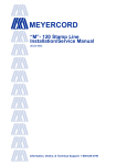
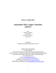
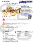
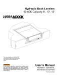
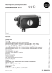
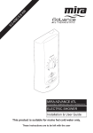
PD Pump Systems
NESLAB P/N 000878
Rev. 08/15/96
Service Manual
1
Contents
General Information
Identification .................................................................................................................... 2
Application ...................................................................................................................... 3
Flow diagram .................................................................................................................. 4
Theory of Operation ........................................................................................................ 5
Pressure / flow curve ....................................................................................................... 6
Fluids .............................................................................................................................. 7
Wetted parts ................................................................................................................... 7
Troubleshooting
No Flow .......................................................................................................................... 8
Pump Noise .................................................................................................................. 10
Low Flow and/or Pressure ............................................................................................ 12
Leaks ............................................................................................................................ 13
Pressure gauge always zero ......................................................................................... 14
Pressure gauge incorrect .............................................................................................. 15
Motor operation............................................................................................................. 16
Motor Temperature ....................................................................................................... 17
Component Repair and Replacement
Pump Replacement ...................................................................................................... 18
Motor Replacement ...................................................................................................... 20
Coupling ....................................................................................................................... 22
Pressure Gauge Replacement ...................................................................................... 24
Pressure Gauge Orifice ................................................................................................ 25
Check Valve ................................................................................................................. 26
Testing the Check Valve .......................................................................................... 27
Replacing the Check Valve ...................................................................................... 28
Check Valve Cross-section ...................................................................................... 28
Relief Valve Adjustment (External) ................................................................................ 30
Capillary Tube............................................................................................................... 31
Adjustments and Maintenance
Priming ......................................................................................................................... 32
Relief Valve (Internal) .................................................................................................... 33
Pressure Adjustment ..................................................................................................... 34
Coupling Lubrication ..................................................................................................... 37
Motor Lubrication .......................................................................................................... 38
Strainer - PD1 .............................................................................................................. 40
Strainer - PD2 .............................................................................................................. 42
Parts List ........................................................................................................................... 44
2
Figure 1
Identification
This section is for maintenance of positive
displacement pumps manufactured by
PROCON®. These are brass pumps which
match one of the above drawings.
3
Application
The pump type used in a recirculating chiller system is determined
by the requirements of flow and pressure. This chart illustrates
which pump family is suitable for various combinations of flow and
pressure.
If the pump system does not deliver the required flow and pressure
on initial installation, the requirements should be compared to the
catalog pump curves to confirm the pump is correctly sized to the
application.
If the pump system has delivered the required flow and pressure
in the past, and the application/installation is unchanged; it is safe
to assume a degradation in performance has occurred and can be
corrected.
Figure 2
4
5
Figure 3
Theory of
Operation
The PD (Positive Displacement) pump is a type of rotary vane
pump, known as a carbonator pump due to its widespread use in
the beverage industry. Four vanes are captive to a rotor which
connects to the motor shaft. The rotor spins inside a liner. The
rotor and liner are on different centers, providing an eccentric
cavity. Opposing vanes are connected by push rods. As one vane
is pushed into the rotor slot by the approaching liner, the opposing
vane is pushed out of the rotor slot, maintaining firm contact with
the retreating liner.
Figure 4
Fluid enters the liner cavity and is trapped between two vanes. As
the vanes rotate inside the liner, the eccentric alignment gradually
decreases the volume available to contain the fluid. When the
rotating trapped fluid finally encounters an outlet, it is squeezed out
at high pressure.
The result is a consistent flow rate, essentially regardless of system pressure. The pump curve approximates a straight line. Thus,
this pump family is designed to deliver low flow rates and high
pressures.
Disassembly of the pump is not recommended. Restoration of
performance is unlikely due to high machining tolerances required.
Any internal pump failure should be resolved by replacing the
pump. The manufacturer (Procon®) accepts removed pumps for
rebuilding.
6
Figure 5
7
Fluids
This is a list of some typical fluids which may be used in a PD
pump system.
Glycol, ethylene - up to a 50% concentration in water. Laboratory or reagent grade is typically used. Automotive antifreeze is
not recommended.
Glycol, propylene - up to a 50% concentration in water. Laboratory or reagent grade is typically used. Automotive antifreeze is
not recommended.
Water, deionized - up to a resistivity of 1.8 megohm/cm.
Water, single distilled
Water, tap
Wetted Parts
The following materials are in contact with the circulating fluid in a
PD pump system.
PVC
Copper
Bronze
Brass
Stainless Steel
Teflon® thread sealing tape
Nickel-plated copper
Carbon-graphite pump vanes and liner
8
Troubleshooting chart - No Flow
9
Figure 6
Troubleshooting chart: No Flow (continued)
Figure 6a
10
Troubleshooting chart: Pump Noise
Figure 7
11
Troubleshooting chart: Pump Noise (continued)
Figure 7a
12
Troubleshooting chart: Low Flow and/or Pressure
Figure 8
13
Leaks
The flange area of the pump has assembly holes at the top and the
bottom. Fluid leaking out of either hole indicates a shaft seal
failure. The seal has a limited ability to seat around imperfections.
If this is a new pump, allow it to run for 24 hours and re-inspect. A
continuous leak will require pump replacement. Field replacement
of the shaft seal is not practical.
Certain fluids will deteriorate the pump shaft seal. Highly deionized
water will leach ions out of the seal material, causing it to lose
flexibility. This will cause leaks. Deionized water must be used with
caution, and with monitoring of the deionization level. See FLUIDS
for further details.
Figure 9
14
Troubleshooting chart: Pressure gauge always zero
Figure 10
15
Troubleshooting Chart: Pressure gauge incorrect
Figure 11
16
Troubleshooting Chart: Motor operation
Figure 12
17
Motor Temperature
Many times users are concerned that motors are operating too
hot. It should be understood that a properly-loaded motor will reach
a shell temperature hot enough to cause burns if touched. This is a
normal condition.
The nameplate of the motor may have a specification for RISE.
This is the temperature the shell of the motor will attain above
ambient (inside the case of the machine, not room ambient). For
example, if the nameplate RISE is 90°C (194°F), and the motor is
operating in a 30°C (86°F) ambient; the shell of the motor may
attain 120°C (248°F) which is well above the boiling point of
water!
In the absence of a RISE specification, the nameplate will specify
the motor as Class A or B. Class A motors may not exceed 105°C
(221°F). Class B motors may not exceed 130°C (266°F).
Single-phase motors used by NESLAB are all internally thermally
protected.* The motor nameplate should carry the legend Thermally protected. If the motor is still running, it is below the trip
point of the thermal protector; and therefore is within operating
range. If the motor is indeed too hot, it will cycle on and off on the
thermal protector - and flow will be observed to stop and start.
Internal thermal protectors are all automatic reset. The
motor will restart without warning when the thermal protector resets.
The thermal protector has a wide hysteresis (dead band), and the
motor must cool down almost to ambient before reset. This may
take considerable time due to the mass of the motor.
* One exception: Certain blue IMOFA-brand motors used in CFT units for
export to Europe have no internal thermal protector, but rather an external
circuit breaker mounted in the control box.
18
Pump Replacement
Tools required:
Bucket
Nut driver
5/16" Wrench
Adjustable Bench Vise
Torque-type screwdriver, capable of 30 in/lb (170 cm/kg)
Torque-type wrench, 5/16", capable of 50 in/lb (280 cm/kg)
1. Disconnect unit from line voltage.
2.
Drain the fluid from the system.
3. Loosen the hose clamp on each of the pump fittings using a
5/16" nut driver as soon as practical. Hose removal will be
much easier if the hose is allowed to relax for 10-15 minutes
after each clamp is loosened.
4. Loosen the V-band clamp and slide it up against the motor.
5. Pull the hoses off the hose fittings.
6. Remove the pump from the unit with the fittings intact.
7. Place the pump in a vise and remove the fittings from the
pump. They can generally be unscrewed without
desoldering. Don’t squeeze the round part of the pump in
the vise! The vise should hold the pump by the square boss
area just below the fittings.
8. Install the fittings in the new pump using Teflon® tape as a
sealant. Support the pump body in a vise or use a backup
wrench.
9. If soldering must be done on the fittings, do so before
installing them in the pump. Solder balls dropping into the
pump will destroy the vanes. If soldering must be done to
the fittings while on the pump, orient the pump so the
openings face downwards. Always use a soft solder: either
50/50 or 95/5 is acceptable.
10. Check the lubrication cup on the motor shaft. Refer to
COUPLING LUBRICATION for details.
19
11. Check that the slot in the motor shaft is sharply rectangular,
without undue wear. The motor should also be replaced if its
slot is worn.
12. Be aware the coupling is not symmetrical! The wide end fits
in the motor and the narrow end fits in the pump.
13. Add some circulating fluid into the pump inlet fitting now to
assist in priming later.
14. Ensure mating flanges of both pump and motor are clean
and free of burrs that may have occured during handling.
File any burrs smooth. Remove and discard the foam
shipping strip from the coupling if it is present.
15. Attach pump to motor, guiding coupling into place.
16. Observe that flanges mate squarely. Tighten V-band clamp
to 15 - 30 in/lbs (85 - 170 cm/kg) of torque.
17. Install hoses onto fittings. If they do not slide on easily, apply
a small film of liquid hand detergent to the hose barbs.
18. Torque hose clamps to 50 in/lbs ( 280 cm/kg).
NOTE: Nylon-reinforced hose tends to cold-flow, so the clamps
will need to retorqued later. (The hose clamps do not actually
loosen, but rather the hose O.D. decreases!) It is best to give
them a final torqueing just prior to leaving the job site. Explain to
the customer that a further torqueing may be required the following day - and that a drip developing at a hose clamp is a
result of cold-flow and not poor workmanship.
20
Motor Replacement
Tools required:
Wrench, 1/2" open-end or combination
Nut driver, 5/16"
Torque wrench, capable of 30 in/lb (170 cm/kg)
NOTE: The motor may be replaced without opening the fluid
system. Draining the unit is not necessary.
Ensure the unit is physically disconnected from line voltage
before attempting motor replacement. Turning the unit’s
power switch off is not adequate to provide safety.
1. Loosen the V-band clamp between the pump and the motor.
Pull the pump away from the motor to separate them.
2. Remove the nuts from the motor mounts using a 1/2"
wrench. If the top nuts are not accessible, remove the
bottom nuts by reaching under the shelf. The motor will
come out as long as one nut is removed from each motor
mount ... it doesn't matter whether from the top or bottom.
3. Jockey the motor off the shelf so the electrical connection
box is accessible. Remove the cover.
4. Disconnect wires, noting which terminals are used. Remove
old motor.
5.
If a bronze pump coupling is being used between the pump
and motor, install a lubrication cup on the motor shaft as
described in COUPLING LUBRICATION. This step is not
required if a nylon coupling is used.
6. Turn the shaft of the new motor a few revolutions by hand.
21
7. Connect wires to the new motor. Position new motor in the
unit.
Eye protection must be worn during this step.
8. Temporarily provide power to the motor. Jog the motor
briefly and observe that the direction of rotation matches the
arrow on the front of the pump. The motor shaft should turn
clockwise as viewed from the pump end.
9. Check that the slot in the pump is sharply rectangular,
without undue wear.
10. Be aware that the coupling is not symmetrical! The wide end
fits in the motor and the narrow end fits in the pump.
11. Ensure mating flanges of both pump and motor are clean
and free of burrs.
12. Join pump and motor, guiding coupling into place.
13. Check that flanges align tightly. Tighten V-band clamp to 15
- 30 in/lbs (85 - 170 cm/kg) of torque.
22
Coupling Types
1. BRONZE COUPLING
The bronze coupling is a sacrificial coupling. It is a softer metal
than either the steel pump bearing race or the steel motor shaft.
The coupling will wear to avoid wearing these more critical
components. The coupling is also intended to shear in two in
the event the pump stops unexpectedly due to foreign matter in
the pump, or seizure. This protects the motor by unloading it
and allowing it to continue turning.
A new coupling is supplied with replacement PD pumps. It is
temporarily held in place with a soft foam strip. This strip should be
removed and discarded.
The coupling is slightly asymmetrical. The wide tab fits in the
motor, and the narrow tab fits in the pump.
NESLAB adds a lubrication cup to the motor shaft on PD pumps
using bronze couplings. This has been found to extend the useful
life of the coupling. See COUPLING LUBRICATION.
Figure 13
23
Coupling Types (continued)
2. NYLON COUPLING
Some PD pumps use a straight nylon coupling. This coupling is
slightly tapered. The wide end fits in the motor, and the narrow end
fits in the pump. It does not require the lubrication cup used with
the bronze coupling.
The bronze and nylon couplings are interchangeable. There is
no particular advantage to using one or the other.
3. CAPTIVE COUPLING
Older PD-1 pumps have a captive tab emerging from the pump
which is actually the end of the rotor shaft. This tab mates directly
with the motor slot. There is no removable coupling on these
pumps.
The current PD-1 pumps have the same removable coupling
(bronze or nylon) which is used on the PD-2 pumps.
The captive coupling pumps are no longer available and may be
directly replaced by the removable coupling style pumps.
24
Pressure Gauge Replacement
1. Disconnect the unit from line voltage.
2. Remove fitting nut from the rear of the adapter fitting. The
fitting nut will be held captive to the capillary tube by the
ferrule.
3. Remove the adapter fitting.
4. Remove clamp bracket(s).
5. Pull the gauge out of the panel hole from the outside.
6. Apply Teflon® tape to the nipple of the new gauge.
7. Mount the new gauge using the clamp bracket(s).
8. Install the adapter fitting.
9. Retighten fitting nut. (Do not use Teflon® tape here).
10. Turn unit on and check for leaks.
Figure 14
25
Pressure Gauge Orifice
The mini style pressure gauge, 1 1/2 in ( 4 cm) diameter, has a
small orifice plate between the gauge nipple and the diaphragm.
This is intended to dampen any needle vibration. The orifice can
become clogged by a small piece of dirt. If this happens, the
gauge will read zero all the time.
Before disassembly, confirm that the needle is on the correct side
of the stop pin. If incorrect, the gauge has been destroyed by
overpressure and will require replacement.
Figure 15
To clean the orifice, remove the adapter fitting from the gauge.
Insert a small needle or similar probe into the gauge nipple. Locate the orifice and twirl the needle in the opening. This should
push any debris inside the gauge where it will be trapped out of
trouble. (System pressure will prevent any such trapped dirt from
"backing up" into the orifice). Reconnect fittings and test the
gauge.
Figure 16
26
Check Valve
(Installed on HX units only)
The check valve is intended to keep the tank from siphoning dry
if the hose is removed from the return fitting. The valve is located upstream from the return fitting.
There are two styles of checkvalves used. The mechanism of
the style shown in Figure 17 consists of a Teflon® seat on a
weighted hinged flapper; the one shown in Figure 18 is of a
spring-loaded metal-to-metal design. The mechanism is accessible through the access cover. This need not be opened under
normal use, as there is no periodic maintenance required on
either style checkvalve.
Figure 17
Check Valve
27
Figure 18
Testing the Check Valve
1. Remove the hose from the return fitting. (If the return line
drains at this point, the valve is stuck open).
Figure 19
2. Insert a hose from a pressurized gas source (such as nitrogen or compressed air) into the return fitting. Cup your hand
around the fitting to provide a "seal".
3. Apply a burst of gas into the fitting. You should hear a clickclick sound as the seat flops up and down.
Note: If there is fluid trapped in the return line between the valve
and the tank, it will drain out during this step.
28
Replacing the Check Valve
NOTE: Any soldering to the check valve body must be done
carefully to avoid melting the Teflon® seat.
1. Open the service access cover.
2. Insert a bent wire such as a coat hanger to pull the seat
open and secure it. This keeps the Teflon® from contacting
the hot valve body.
3. Wrap the valve body with a damp rag.
4. Use a low temperature solder such as 95/5 or 50/50. Use a
hot flame and work quickly.
5. Do not release the seat until the body is cool.
CHECK VALVE CROSS-SECTION
Figure20
29
Ball and Spring Type Check Valves
Older check valves use a mechanical ball and spring arrangement. Performance of this type can usually be restored by
polishing the ball using Scotch-Brite® or a similar abrasive pad.
Repair of this type, beyond cleaning, is not practical. If a failed
valve of this type is found, it should be replaced by the current
Teflon® seat type.
Lubrication
A small amount of molybdenum lubricant (see Coupling Lubrication) on the access cover threads will assist in sealing and
provide easier future service.
30
Relief valve adjustment (external)
Leaks occurring at the locknut generally may be solved by tightening the locknut. The locknut serves two functions: It prevents the
adjustment stem from moving, and it tightens against the packing
gland inside the valve to prevent leaks. Leaks occurring at the
large nut (labelled "DO NOT ADJUST" in the diagram) should be
solved by replacing the valve.
Replacement of the valve is done by removing any hoses, then
transferring the fittings to a new valve. Teflon® tape should be
used on the threaded fittings. Replacement of the valve will require the system pressure to be reset.
Refer to ADJUSTMENTS and MAINTENANCE: PRESSURE
ADJUSTMENT for details on setting the system pressure.
Relief valve adjustment
Figure 21
31
Capillary Tube
The pressure gauge is connected to the pump discharge line by a
capillary tube of 0.075" (0.191 cm) I.D. (Inside Diameter). The
length is determined by measuring the distance of the path from
the discharge line to the pressure gauge and adding 27" ( 68 cm ).
This additional length will allow a 3 turn coil of approximately 3" (
7.6 cm ) diameter to be included. This coil will dampen any needle
vibration and allow future service.
TIP: A 3" (7.6 cm) diameter coil may be
formed easily using an aerosol can as a
winding form.
The capillary tube I.D. 0.075" (0.191 cm) was chosen because the
O.D. (Outside diameter) of 0.125" (0.32 cm ) provides a snug fit in
the adapter fitting.
The gauge indicates system back pressure, not pump capacity. A
unit connected to a low back-pressure system (parallel manifolds,
or short lines of large diameter) may indicate 0 or a very low
pressure. In other words, the gauge indication reflects reflects
system demand, not pump supply.
32
Priming
The pumps are self-priming only if plumbed in a flooded-suction
configuration, i.e. the fluid flows continually downhill from the
tank to the pump inlet. NESLAB CFT and HX applications are
not plumbed flooded-suction, so priming may not be automatic.
If flow does not start immediately, shut the unit off. Remove the
fitting nut from the rear of the adapter fitting on the pressure
gauge. (The fitting nut is held captive to the cap tube by a ferrule.)
This allows the cap tube to become a vent for the discharge line,
providing an escape path for air trapped in the pump. Place a rag
over the end of the cap tube. Start the unit. When fluid is observed
flowing steadily from the cap tube, reseat it in the adapter fitting
and tighten the fitting nut.
When installing a new pump, add a small amount of fluid to the
inlet of the pump during installation to assist priming.
See
PUMP REPLACEMENT for details.
Pressure Gauge Fittings
Figure 22
33
Relief Valve (Internal)
The relief valve built into the pump temporarily protects against
dangerous overpressure. The relief valve is set at the pump factory
and confirmed at NESLAB. The relief valve setting appears
stamped in the brass as shown. (The illustration shows the position of the stamping only - your actual value may differ). The flow
will fully bypass from the outlet to the inlet at the specified relief
valve setting. The relief valve actually begins to crack open and
allow bypass flow approximately 50 PSI (345 kPa) below the
stamped relief valve setting.
Turning the pressure adjustment screw clockwise will increase the
relief valve setting.
NESLAB supplies an additional external relief valve, set to a lower
setting, to provide primary pressure control. The internal relief
valve is a safety feature and should not be relied on to provide
primary pressure control. Changing the setting on this internal
relief valve is not recommended.
See PRESSURE ADJUSTMENT for details on balancing the
settings of both internal and external relief valves.
Figure 23
34
Pressure Adjustment
The fluid system contains two relief valves: An internal one in the
pump, and an external one on the pump discharge line. Because
of their ability to interact, adjustment must be done in a certain
sequence.
Figure 24
35
1. Turn unit off. Locate the external relief valve. Loosen the
locknut. Turn the threaded stem all the way in (clockwise).
This manually closes the valve by setting it to an infinite
value.
External Relief Valve
Figure 25
2. If the unit is not plumbed to an application, install a loop of
hose between the supply and return fittings. Turn unit on.
NOTE: The external relief valve may drip
while the locknut is loose. This is normal.
3. CFT units: Crimp the loop of hose flat using a pair of visegrips. HX units: Turn flow control valve completely clockwise
if a round handle, or fully - if a lever handle. The pressure
gauge should rise to a high value. It is now indicating the
internal relief valve setting.
Internal Relief Valve
36
Figure 26
Internal Relief Valve Adjustment
4. Remove the acorn nut on the side of the pump. Adjust the
pump pressure adjustment screw (under the acorn nut) until
the gauge indicates the value stamped on the pump. If no
value is shown, adjust to 90 PSI (620 kPa) . Turning the
screw CW will increase the pressure setting. Replace the
acorn nut.
Internal Relief Valve
Figure 27
External Relief Valve Adjustment
5. Back out the threaded stem on the external relief valve
(CCW). As the setting drops below the internal valve setting,
the gauge will now indicate the external valve setting.
Continue until the gauge indicates 80 PSI ( 550 kPa ) or
desired setting. Tighten the lock nut.
6. The external relief valve is intended for coarse pressure
limiting, not regulation. For precise pressure regulation, an
external bypass type regulator is recommended.
NOTE: The minimum pressure achievable
using the provided external relief valve is
about 35 - 45 PSI ( 240 - 310 kPa). If lower
operating pressures are required, the addition of an external bypass-type regulator is
recommended. NESLAB sells various EPR
(External Pressure Regulator) kits for this
purpose. Contact a NESLAB sales representative37
for information.
Coupling Lubrication
NESLAB has found that providing lubrication to the bronze coupling will extend its useful life. NESLAB installs a heat shrink
sleeve on the motor shaft as a cup to contain the lubricant. If this
cup is still intact, it should be reused. If the cup is frayed or otherwise damaged, it should either be replaced or removed completely.
Obtain a piece of ¾" ( 2 cm ) heat shrink tubing. Cut the piece to
1.5" ( 4 cm ) long. Fully seat the tubing on the motor shaft. Heat
evenly with a heat gun. Insert a small glob (pea-sized) of lubricant.
NESLAB uses a molybdenum-based lubricant with the trade name
NEV-R-SEEZ®. This lubricant is intended primarily for use in
automotive exhaust systems to allow future disassembly, and is
commonly available at automotive supply stores. The grease base
will eventually dry up and leave the molybdenum behind as a
lubricant.
The intent is to provide lubricant between the coupling and the
motor shaft. Do not lubricate between the coupling and the pump
slot.
The nylon coupling does not require lubrication.
38
Motor Lubrication
Figure 28
PD pumps are generally powered by sleeve-bearing carbonator
type motors, NEMA type 48YZ**. These motors must be run on a
horizontal-shaft orientation, due to the internal oil reservoir. A wick
runs from the reservoir to each bearing. The motor will have either
one or two lubrication ports, depending on the manufacturer.
A good source of oil is the 3-IN-ONE®
brand squeeze cans manufactured by
Boyle-Midway, Inc. It should be available
at hardware stores or electrical supply
houses.
Figure 29
**exception: Blue IMOFA-brand motors and grey MAC-brand
motors are ball bearing and require no periodic lubrication.
39
The motor should be oiled periodically in accordance with the
nameplate directions. In the absence of legible lubrication instructions, add 30 - 35 drops of SAE 20 non-detergent oil to each oil
port. Use the following table as a frequency guide:
Duty
Oiling frequency
Continuous
Annual
Regularly
Every 2 years
Occasional
Every 5 years
Table 1
Figure 30
40
Strainer - PD1
All PD pumps require a 100-mesh strainer on the inlet side of the
pump. Particles that are trapped are of sufficient size to destroy
the vanes of the pump. Never run the pump with a missing or
damaged strainer screen.
The PD1 pump has an internal strainer screen.
Figure 31
41
Periodic cleaning of the screen is necessary. The screen may be
removed without significant fluid loss. Turn the unit off and disconnect from the power source. Have a clean rag handy which has
been dampened and twirled into a pointy shape. Remove the
strainer cap using an open end or socket wrench. Pull out the
screen and quickly stuff the rag into the opening. Some spillage
will be unavoidable. If a helper is available, the helper could hold
the rag tightly in place while you clean the screen. (You can temporarily reinstall the strainer cap finger tight.)
The debris will be inside the screen. Clean the screen under
running water. A toothbrush is a handy tool for cleaning. Trim the
bristles to 1/2 length for a PD1 screen. An alternative is to take a
coarse paper towel (the brown roll type), dampen it and twist it into
a spiral. Pull it through the screen several times, turning it as it
passes. Inspect the screen closely for damage - particularly holes.
It is advisable to keep a spare screen on hand. The spare may be
quickly substituted for the dirty screen, minimizing downtime and
fluid loss. Then the dirty screen may be cleaned at your leisure and
retained as the spare for next time.
42
Strainer - PD2
All PD pumps require a 100-mesh strainer on the inlet side of the
pump. Particles that are trapped are of sufficient size to destroy
the vanes of the pump. Never run the pump with a missing or
damaged strainer screen.
The PD2 pump has an external strainer screen, located on the
pump inlet line. It may be a brass body type (Figure 32), a
plastic type (Figure 33), or it may be a basket type inside the
reservoir on HX units.
Figure 32
Figure 33
43
Periodic cleaning of the screen is necessary. The screen may be
removed without significant fluid loss. Turn the unit off and disconnect from the power source. Have a clean rag handy which has
been dampened and twirled into a pointy shape. Remove the
strainer cap using an open end or socket wrench. Pull out the
screen and quickly stuff the rag into the opening. Some spillage
will be unavoidable. If a helper is available, the helper could hold
the rag tightly in place while you clean the screen. (You can temporarily reinstall the strainer cap finger tight.)
The debris will be inside the screen. Clean the screen under
running water. A toothbrush is a handy tool for cleaning. It will fit
nicely inside the PD2 screen. An alternative is to take a coarse
paper towel (the brown roll type), dampen it and twist it into a
spiral. Pull it through the screen several times, turning it as it
passes. Inspect the screen closely for damage - particularly holes.
It is advisable to keep a spare screen on hand. The spare may be
quickly substituted for the dirty screen, minimizing downtime and
fluid loss. Then the dirty screen may be cleaned at your leisure and
retained as the spare for next time.
A small amount of molybdenum lubricant (See COUPLING LUBRICATION) on the PD2 strainer cover threads will assist sealing and
provide easier future service.
44
Table 2
Part
Number
012869
009142
008123
008124
004185
013123
008445
008295
008125
008126
008120
009057
009212
009083
009200
008423
008142
008576
008205
008159
008143
008181
008155
008694
009058
009347
013459
009384
004626
008899
Parts List
Description
Adapter Fitting for pressure gauge
Check vlave
Clamp, V-band
Coupling, Bronze 90 degree
Coupling, Nylon
Heat Shrink, ¾" diameter
Motor mount
Motor, ½ HP, 115/230v
Motor, 1/3 HP, 115v
Motor, 1/3 HP, 208-220v
Motor, ¼ HP, 115v
Pressure gauge, 1.5" panel mount, 0-100 PSI
Pressure gauge, 2" panel mount, 0-100 PSI
Pressure gauge, 2" panel mount, 0-160 PSI
Pressure gauge, 2" stem type, 0-100 PSI
Pump, PD1, brass, bronze coupling. Replaced by 008576
Pump, PD1, brass, captive coupling. Replaced by 008423
Pump, PD1, brass, nylon coupling
Pump, PD1, brass, optional hi temp Viton® seal
Pump, PD1, stainless steel
Pump, PD2, brass
Pump, PD2, optional hi temp Viton® Seal
Pump, PD2, stainless steel
Relief valve, external
Relief valve, external. Replaced by 008694
Strainer assembly, bronze
Strainer screen, PD1 replacement
Strainer screen, PD2 replacement
Strainer, POLYP 100 mesh
Check Valve, ½", SWT, BRZ, WTR
45
Usage
PD1
Usage
PD2
X
X
X
X
X
X
X
X
X
X
X
X
X
X
X
X
X
X
X
X
X
X
X
X
X
X
X
X
X
X
PD Pump Systems
NESLAB P/N 000878
Rev. 08/15/96
Service Manual
46