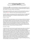
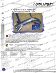
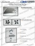
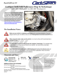
1
Part #GEN-6-991
CorkSport DISI MZR Fuel Injector Seals
2007 – 2013 Mazdaspeed 3 & 2006 – 2007 Mazdaspeed 6
Thank you for purchasing the
CorkSport DISI MZR Fuel Injector Seals
for the 2007-2013 Mazdaspeed 3 &
2006-2007 Mazdaspeed 6. Constructed
from beryllium copper; the CorkSport
fuel injector seals will lock in every PSI
of boost so that every bit of your hard
earned horsepower keeps you moving
forward. Please let us know what you
think by submitting a review at:
https://corksport.com/mazdaspeed-3fuel-injector-seals.html
Pre-Installation Notes:
Make sure your vehicle is completely cooled down prior to starting installation. If you are
going to work on your car within an hour or two of having driven it, use a fan to cool off the car.
These instructions were written for reference only and the use of a factory service manual is
recommended. Please read these instructions thoroughly prior to starting installation.
These instructions were made using a 2013 Mazdaspeed 3. Installation for earlier
Mazdaspeed 3 and Mazdaspeed 6 will be similar.
Materials and Time:
General Info.
Part #: GEN-6-991
Time Est: 4 - 6 hours
Wrench Rating: 5/5
Parts List
One (1) Set of Four (4) CorkSport DISI MZR Fuel
Injector Seals
One (1) Booklet of CorkSport Installation
Instructions
Tooling List
Flat Head Screwdriver
Phillips Head Screwdriver
Large Jaw Pliers
Need Nose Pliers
8mm Wrench
22mm Wrench
Small Vise-Grips or C-Clamps
Scotch-Brite
Tooling List
8mm Shallow Socket
8mm Deep Socket
10mm Deep Socket
12mm Deep Socket
T-40 Torx Socket
4” Extension
3/8” Drive Ratchet
Small Fuel Catch Container
Additional Parts List (not included)
Four (4) Fuel Injector O-Ring (L3K9-13-253) Recommended
Four (4) Fuel injector O-Ring Grommet (L3M8-13-252) Recommended
One (1) Intake Manifold Gasket (L3K9-13-111) Dependent on Condition
One (1) Throttle Body Gasket (L3K9-13-655) Dependent on Condition
Need Help With Your Installation?
Call (360) 260-CORK
Part #GEN-6-991
Order of Operations & Table of Contents
Engine Disassembly
Section 1: Intercooler and Intake Removal
Section 2: Intake Manifold Accessories Removal
Section 3: Throttle Body Removal
Section 4: EGR Tube Removal
Section 5: Intake Manifold Removal
Section 6: Fuel Rail Removal
Section 7: Fuel Injector Removal
Pg. 2-3
Pg. 4-6
Pg. 7
Pg. 8
Pg. 9
Pg. 10-11
Pg. 12
Injector Seal Installation
Section 8: Fuel Injector Assembly
Section 9: Fuel Injector Installation
Pg. 13
Pg. 14
Engine Assembly
Section 10: Engine Reassembly
Pg. 15
Fuel System Priming
Section 11: Priming the Fuel System & Initial Start Up
Pg. 16
Need Help With Your Installation?
Call (360) 260-CORK
1 of 16
Part #GEN-6-991
Detailed Instructions
These instructions were made using a 2013 Mazdaspeed 3. Installation for earlier
Mazdaspeed 3 and Mazdaspeed 6 will be similar.
1. Intercooler and Intake Removal
a) Remove the negative battery terminal and place the plastic
cover back over the battery (green arrow in Figure 1a).
b) Remove the two 10mm bolts fastening intercooler shroud to the
intercooler. Push the shroud towards the firewall to unhook it
and remove it from the vehicle (red circles in Figure 1b).
Figure 1a
We recommend using plastic Ziploc bags and a sharpie
to label all bolts and parts throughout the install.
c) Remove the clamps for the throttle body and turbo boost
tubes from the intercooler. Use a 10mm socket to loosen
the clamps (green circles in Figure 1c).
Figure 1b
d) Detach the bypass valve (BPV) from
the intake. Remove the vacuum
signal hose (red arrow), and the
large BPV to intake hose by
compressing the clamp with pliers
(green arrow in Figure 1c). Leave
the bypass valve attached to the
intercooler pipe.
Figure 1c
Need Help With Your Installation?
Call (360) 260-CORK
2 of 16
Part #GEN-6-991
1. Intercooler and Intake Removal (continued)
e) Remove the three (3) 12mm nuts fastening
the intercooler to the top of the engine and
remove the intercooler from the vehicle by
pulling upward (Figure 1d).
Figure 1d
f) Remove the intake. Loosen the hose clamp
connecting the intake elbow to the turbo
inlet pipe with a 10mm socket wrench (red
circle in Figure 1e).
g) Remove the breather pipe from the valve
cover (red arrow in Figure 1e) and unplug
the MAF sensor (green arrow in Figure 1e).
Figure 1e
h) Remove intake from engine bay.
Need Help With Your Installation?
Call (360) 260-CORK
3 of 16
Part #GEN-6-991
2. Intake Manifold Accessories Removal
Figure 2a
a) Disconnect the swirl vane wires (red arrow in Figure 2a) Using needle nose pliers, remove the connector
from the bracket by squeezing in the direction of the green arrows in Figure 2a
b) Remove the swirl vane controller box (red circles in Figure 1b) with an 8mm socket, then disconnect the
electrical circuit (green arrow) and lay the box on top of the engine.
Figure 2b
Need Help With Your Installation?
Call (360) 260-CORK
4 of 16
Part #GEN-6-991
2. Intake Manifold Accessories Removal (continued)
c) Locate the connector that runs to
the spark pugs. This is located at the
front passenger location of the intake
manifold. Move the gray wrapped
wires out of the way. Shown in
Figure 2c.
Figure 2c
d) Disconnect the wire plug and lay it on top of
the engine and remove brackets. (Red circles
in Figure 2c & 2d) Use an 8mm socket and
wrench to remove the connectors bracket and
the dipstick bracket.
e) Disconnect the MAP
sensor connector,
with a flathead
screwdriver if needed.
Green circle and
arrow in Figure 2d.
Figure 2d
Need Help With Your Installation?
Call (360) 260-CORK
5 of 16
Part #GEN-6-991
2. Intake Manifold Accessories Removal (continued)
f) Remove the vacuum hose with the blue tab. Use a flathead screwdriver to pop the clip out as shown
in the blue circle in Figure 2e.
g) Remove the vacuum line with the red collar. Use a flathead screwdriver to hold the red collar down
while gently pulling the vacuum hose upward. Shown with the blue arrow in Figure 2e.
Figure 2e
h) Open the two black plastic hose clamps. Use a flathead screwdriver to pop the clamp open as shown
in the green circle sin Figure 2e. Move the hose to the top of the engine, out of the way.
Need Help With Your Installation?
Call (360) 260-CORK
6 of 16
Part #GEN-6-991
3. Throttle Body Removal
a) Unclamp the throttle body coolant line and slide the clamps back. Use the needle nose pliers to
grab and loosen the clamps. Green circles in Figure 3a
Do not remove the hoses off the ports until the vise grips or c-clamps have been installed in the
next step. Failure to do so will led to messy coolant everywhere!
Figure 3a
b) Clamp the coolant hoses with the visegrips or c-clamps to stop the coolant flow.
Excessive clamping force is not required.
Clamping location shown with the green
arrows in Figure 3a.
c) Remove the throttle body inlet hose using
a 10mm socket wrench. Shown with the
blue circle in Figure 3a.
d) Remove the throttle body using an 8mm
socket wrench and extension. The four
bolts are shown with red circles in Figure
3b. Peel the gasket off the intake manifold
for further inspection (be careful to not
bend the gasket) Gasket tab shown with
blue arrow in Figure 3b.
Figure 3b
Need Help With Your Installation?
Call (360) 260-CORK
7 of 16
Part #GEN-6-991
4. EGR Tube Removal
a) Loosen the EGR tube at the intake manifold with a
22mm wrench, shown with the red circle in Figure 4a.
b) Remove the EGR tube at the engine with an 8mm
socket wrench, shown with green circles in Figure 4a.
Be sure to not lose the small gasket between the
engine and EGR tube.
Figure 4a
The EGR tube at the engine can be removed without the removal of the turbo inlet pipe, but is
significantly easier with the TIP removed. Instructions to remove the TIP are available at
http://www.corksport.com/support/instructions/Axl-6-118-WEB.pdf
Need Help With Your Installation?
Call (360) 260-CORK
8 of 16
Part #GEN-6-991
5. Intake Manifold Removal
a) Remove the fuel rail shield with a 10mm
socket wrench, shown with red circles in
Figure 1a.
b) Remove the intake manifold with a 10mm
socket wrench and 4” extension, shown
with red circles in Figure 5b. Alignment pins
are located at the blue dots.
Figure 5a
Figure 5b
Need Help With Your Installation?
Call (360) 260-CORK
9 of 16
Part #GEN-6-991
6. Fuel Rail Removal
a) Remove the high pressure fuel line bolts
with a 10mm socket wrench, shown with
red circles in Figure 6a.
b) Remove the fuel return line. Twist the
flathead screwdriver to pop the clip loose.
Shown in Figure 6b.
Figure 6a
c) Loosen the high pressure fuel line brackets
with a 8mm socket wrench, shown with red
circles in Figure 6c.
Use a rag and small container to catch the fuel
in the fuel rail.
d) Remove the high pressure fuel line from
the fuel rail. Pull the end out far enough to
empty the fuel rail. Shown in Figure 6d.
Figure 6d
Need Help With Your Installation?
Call (360) 260-CORK
Figure 6b
Figure 6c
10 of 16
Part #GEN-6-991
6. Fuel Rail Removal (continued)
e) Disconnect the fuel pressure wire
shown the red circle in Figure 6e.
f) Remove the fuel injector wiring
harness from the fuel rail. Use a Philips
screwdriver to push the plastic clip in
the directions of the red arrows.(Push
from underneath) Shown in Figure 6e.
Figure 6e
Figure 6f
g) Remove the fuel rail bolts with a 10mm socket wrench, shown with red circles in Figure 6f.
h) Remove the fuel rail by pulling it off the injectors starting at the driver’s side and working your way
across. Red arrow in Figure 6f.
Need Help With Your Installation?
Call (360) 260-CORK
11 of 16
Part #GEN-6-991
7. Fuel Injector Removal
a) Remove the fuel injector wiring harness from the injectors
b) Remove the fuel injector clamps. Use a T-40 torx socket and wrench with a 4” extension. Red circles in
Figure 7a.
Figure 7a
c) Remove the fuel injectors. Rotate the injectors back and forth while pulling them out of the cylinder
head. Rotation direction shown with blue arrows in Figure 7a.
d) Remove the OEM seal. Shown in Figure 7b. The OEM seal may have fallen off during injector removal
and therefore is still in the injector port.
CS Seal
OEM Seal
Figure 7b
Need Help With Your Installation?
Call (360) 260-CORK
12 of 16
Part #GEN-6-991
8. Fuel Injector Assembly
a) Clean the injector and cylinder head ports. Use a scotch bright pad to scrub the injector body clean of
any debris. Clean the injector port in the cylinder head and use a vacuum to suck any debris from the
cylinder. Shown in Figure 8a.
A clean and smooth injector and cylinder port is critical to the sealing performance of the Corksport Seals.
Figure 8a
Figure 8b
b) Inspect the fuel injector O-rings. Verify that the
O-ring still has a round profile, not “square”.
Inspect for tears, nicks, cracks, or anything that
might compromise the seal ability. If
replacement is necessary, the part numbers are
located on the cover page of these install
instructions.
CorkSport recommends the replacement of the fuel
injectors O-rings.
The CorkSport Seals are manufactured from a softer
malleable material, special care must be taken when
handling them.
c) Install the CorkSport injector seals onto the
injectors. DO NOT push the seals onto the
injectors from the outer lip. DO push the seal on
by applying pressure close to the injector nozzle
shown with the red arrows in Figure 8c. The seal
will be snug going on and should leave a very
small gap shown with the blue arrow in Figure 8b.
Need Help With Your Installation?
Call (360) 260-CORK
Figure 8c
13 of 16
Part #GEN-6-991
9. Fuel Injector Installation
a) Install the injectors and the place the clamps around the injectors.
b) Torque the injector clamps to OEM specs. Use a T-40 torx socket and torque wrench with a 4” extension
to torque the bolts to 17-18 ft-lb. Red circles in Figure 9a.
c) Connect the fuel injector wiring harness.
Figure 9a
d) Install the fuel rail. The fuel rail must be pushed onto the injectors strait and parallel. To help the
installation dab a small amount of engine oil onto the injector O-rings. Use a 10mm socket and torque
wrench with a 4” extension to torque the bolts to 13-16 ft-lb. Red circles in Figure 9b.
The intake manifold and fuel rail bolts are slightly different in length. Verify that you are using the correct longer bolts for
the fuel rail. Failure to do so will result in stripped threads.
Figure 9b
Need Help With Your Installation?
Call (360) 260-CORK
14 of 16
Part #GEN-6-991
10. Engine Reassembly
a) Follow the instructions in reverse order for reassembly.
b) Torque all fasteners to OEM specifications.
Toque Specs:
• 8mm Bolts -> 71-97 in-lb (6-8 ft-lb)
• 10mm Bolts -> 13-16 ft-lb
• 12mm Bolts -> 21-25 ft-lb
11. Priming the Fuel System and Initial Start Up
a) Verify that everything is assembled correctly before start up
b) Prime the Fuel System:
a) Keyed Ignitions: With your foot off the clutch, cycle the key on/off until the electric fuel pump
stays on for only 1-2 seconds. (typically 6-8 cycles).
b) Push Button Ignitions: With your foot off the clutch, cycle the push button start on/off until the
electric fuel pump stays on for only 1-2 seconds. (typically 6-8 cycles).
c) Initial Start Up: The engine may start and die quickly, this is due to some air being in the fuel system.
Wait 30 seconds and start the engine again. The engine should stay running at this point. It may take a
few seconds before the engine revs up to its normal start up RPM. This is due to the air in the fuel
system being pushed out.
This completes the installation of your CorkSport Fuel Injector Seals. Inspect for fuel
leaks and any loose fasteners after a few miles of driving then enjoy!
Need Help With Your Installation?
Call (360) 260-CORK
15 of 16
Part #GEN-6-991
What’s Next:
CORKSPORT 2010-2013 Mazdaspeed 3 Downpipe
Get maximum turbo performance and dramatically increase torque
with the Mazdaspeed 3 Power Series Downpipe. The CorkSport
downpipe has been expertly designed to replace the restrictive
element in the Mazdaspeed 3 stock downpipe. Mandrel bent piping
is used to create smooth exhaust flow for dramatic increases in
power. For lasting corrosion resistance and reduced heat transfer to
the engine bay, the CorkSport MS3 downpipe uses polished 3” 304
stainless steel and features TIG welds that offer superior arc and
weld puddle control for a cleaner appearance and precise weld bead
control
CORKSPORT Mazdaspeed MZR Bypass Valve
Add performance and style while protecting your turbo with the
Patent Pending CorkSport Mazdaspeed MZR Bypass Valve. Using
an innovative patent pending design utilizing a wave spring, we
were able to reduce the spring height of the OEM Bypass Valve by
50%. This size reduction provides the same amount of force,
while accelerating the speed of the valve. By increasing speed the
Bypass Valve effectively increases the life of your turbo by
preventing premature wear since the BPV can safely move at
speeds 33% faster than stock or other valves. With the extra
space allowed by the spring we were able to increase piston size
by over 30%.
CORKSPORT Max Flow Fuel Pump Internals
Maximize your stock fuel system while protecting your engine
with the CorkSport MZR DISI Max Flow Fuel Pump Internals.
With well over 2 years of research and development, you can
count on CorkSport to bring innovation to the high pressure fuel
pump on your Mazdaspeed. With hardening surface treatments,
high strength coatings and a machined tolerance that is the best
on the market, our pump internals are ready to give you the most
performance available for your dollar. These pumps are precision
machined, then treated, then coated and then machined again for
a perfect fit and an ultra-high efficiency. That difference in the
real world is going to be higher horsepower capability, safer
air/fuel ratios and the ability to go that much further in the quest
for power without worrying about fuel supply.
Need Help With Your Installation?
Call (360) 260-CORK
16 of 16