1
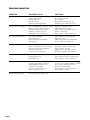
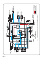
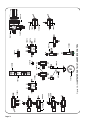
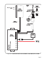
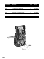
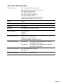
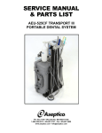
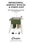
SERVICE MANUAL
& PARTS LIST
ADU-10CF
(NSN: 6520-01-456-7170) Part 1 of 2
P.O. Box 1548 Woodinville, WA 98072-1548
1-800-426-5913 * 425-487-3157 * Fax: 425-487-2608
email: [email protected] * Internet: www.aseptico.com
TABLE OF CONTENTS
General Service Information . . . . . . . . . . . . . . . . . . . . . . . . . . . . . . . . . . . . . . . . . . . . . .3
Inspection & Verification . . . . . . . . . . . . . . . . . . . . . . . . . . . . . . . . . . . . . . . . . . . . . . . . .3
Cleaning & Lubrication . . . . . . . . . . . . . . . . . . . . . . . . . . . . . . . . . . . . . . . . . . . . . . . . . . .3
Dis-Assembly . . . . . . . . . . . . . . . . . . . . . . . . . . . . . . . . . . . . . . . . . . . . . . . . . . . . . . . . . . .4
Handpiece Control/Delivery Head . . . . . . . . . . . . . . . . . . . . . . . . . . . . . . . . . . . . . . . . . .4
Vacuum System/Water System Control . . . . . . . . . . . . . . . . . . . . . . . . . . . . . . . . . . . . . .4
Fiber Optic System . . . . . . . . . . . . . . . . . . . . . . . . . . . . . . . . . . . . . . . . . . . . . . . . . . . . . . .5
TA-97 3-Way Syringe . . . . . . . . . . . . . . . . . . . . . . . . . . . . . . . . . . . . . . . . . . . . . . . . . . . . .6
Troubleshooting Chart . . . . . . . . . . . . . . . . . . . . . . . . . . . . . . . . . . . . . . . . . . . . . . . . . . . .8
System Schematic; Handpiece Control . . . . . . . . . . . . . . . . . . . . . . . . . . . . . . . . . . . . . .10
System Schematic; Vacuum Control . . . . . . . . . . . . . . . . . . . . . . . . . . . . . . . . . . . . . . . .11
Illustrated Parts List
Handpiece Control . . . . . . . . . . . . . . . . . . . . . . . . . . . . . . . . . . . . . . . . . . . . . . . . . . . . . . .12
Vacuum Control . . . . . . . . . . . . . . . . . . . . . . . . . . . . . . . . . . . . . . . . . . . . . . . . . . . . . . . . .13
Case Components . . . . . . . . . . . . . . . . . . . . . . . . . . . . . . . . . . . . . . . . . . . . . . . . . . . . . . .14
HVE & Saliva Ejector Assembly . . . . . . . . . . . . . . . . . . . . . . . . . . . . . . . . . . . . . . . . . . .15
NWS-6 Water System . . . . . . . . . . . . . . . . . . . . . . . . . . . . . . . . . . . . . . . . . . . . . . . . . . . . .16
TA-97 Autoclavable 3-Way Syringe . . . . . . . . . . . . . . . . . . . . . . . . . . . . . . . . . . . . . . . . .17
AA-42 Standard Disc Foot Control . . . . . . . . . . . . . . . . . . . . . . . . . . . . . . . . . . . . . . . . .18
Air Supply Line Assembly . . . . . . . . . . . . . . . . . . . . . . . . . . . . . . . . . . . . . . . . . . . . . . . . .19
Swivel Tray Assembly . . . . . . . . . . . . . . . . . . . . . . . . . . . . . . . . . . . . . . . . . . . . . . . . . . . . .20
KaVo Fiber Optic System . . . . . . . . . . . . . . . . . . . . . . . . . . . . . . . . . . . . . . . . . . . . . . . . .21
Parts List . . . . . . . . . . . . . . . . . . . . . . . . . . . . . . . . . . . . . . . . . . . . . . . . . . . . . . . . . . . . . . .22
Specifications . . . . . . . . . . . . . . . . . . . . . . . . . . . . . . . . . . . . . . . . . . . . . . . . . . . . . . . . . . .27
TABLE OF ILLUSTRATIONS
Handpiece Control/Delivery Head . . . . . . . . . . . . . . . . . . . . . . . . . . . . . . . . . . . . . . . . . .4
Vacuum System/Water System Control . . . . . . . . . . . . . . . . . . . . . . . . . . . . . . . . . . . . . .4
Fiber Optic System . . . . . . . . . . . . . . . . . . . . . . . . . . . . . . . . . . . . . . . . . . . . . . . . . . . . . . .5
3-Way Syringe . . . . . . . . . . . . . . . . . . . . . . . . . . . . . . . . . . . . . . . . . . . . . . . . . . . . . . . . . . .6
System Schematic, ADU-10CF Handpiece Control . . . . . . . . . . . . . . . . . . . . . . . . . . . .10
System Schematic, ADU10CF Vacuum Control . . . . . . . . . . . . . . . . . . . . . . . . . . . . . . .11
Illustrated Parts List, Handpiece Control . . . . . . . . . . . . . . . . . . . . . . . . . . . . . . . . . . . .12
Illustrated Parts List, Vacuum Control . . . . . . . . . . . . . . . . . . . . . . . . . . . . . . . . . . . . . .13
Illustrated Parts List, Case Components . . . . . . . . . . . . . . . . . . . . . . . . . . . . . . . . . . . . .14
Illustrated Parts List, HVE & Saliva Ejector Assembly . . . . . . . . . . . . . . . . . . . . . . . . .15
Illustrated Parts List, NWS-6 Water System . . . . . . . . . . . . . . . . . . . . . . . . . . . . . . . . . .16
Illustrated Parts List, TA-90 Autoclavable 3-Way Syringe . . . . . . . . . . . . . . . . . . . . . . .17
Illustrated Parts List, AA-42 Standard Disc Foot Control . . . . . . . . . . . . . . . . . . . . . . .18
Illustrated Parts List, Air Supply Line Assembly . . . . . . . . . . . . . . . . . . . . . . . . . . . . . .19
Swivel Tray Assembly . . . . . . . . . . . . . . . . . . . . . . . . . . . . . . . . . . . . . . . . . . . . . . . . . . . . .20
KaVo Fiber Optic System . . . . . . . . . . . . . . . . . . . . . . . . . . . . . . . . . . . . . . . . . . . . . . . . .21
Page 2
P.O. Box 1548 Woodinville, WA 98072-1548
1-800-426-5913 * 425-487-3157 * Fax: 425-487-2608
email: [email protected] * Internet: www.aseptico.com
Printed In The USA
GENERAL SERVICE INFORMATION
This service and parts manual offers information and parts lists not available in the ADU-10CF
Operation and Maintenance manual. It will help you better understand how the ADU-10CF
Portable Field Dental Unit works, thereby reducing service time. Exploded parts drawings and
schematics show components in there actual places in the unit relative to one another. Tubing is
coded by color tone and line thickness, and all parts are called out by Aseptico part number, then
listed in reverse numerical order in the Parts List. Parts marked as "Commercial" are those items
that can be purchased at retail hardware stores, and minimize service delays when obtained locally.
Use the information in the Parts List when ordering replacement parts.
Inspection & Operation Verification
To verify that the ADU-10CF unit is functioning properly, connect the unit to a clean compressed
air source providing 60-80 PSI. Switch the master On/Off toggle to the on position. The master
pressure gauge and "On" indicator should indicate pressure. When the water system is attached and
turned on, water canister should pressurize. Depress foot control and observe drive air pressure
from the highspeed line, and lowspeed line when selected. Depress the air/water buttons on the
three-way syringe. Syringe should spray both air and water. With vacuum waste containers attached
to the system, lift the HVE and Saliva Ejector valve from their auto holders with lock out switch in
the on position. Vacuum should switch on, and vacuum generated at each valve.
While system is pressurized, inspect the unit for air or water leaks that could degrade or eliminate
performance. Air filter/water separator drain should be closed, and air filter element inspected.
Element should be replaced when pressure drop across the unit exceeds 10psi differential pressure.
Water canister should be holding pressure at the lid, and the lid gasket inspected. Gasket may
require lubrication or replacement for a proper seal. Inspect the water filter on the water pick-up
tube. Water filter requires replacement if it becomes clogged and restricts water flow. Vacuum waste
container lids should be sealed and holding a vacuum when in operation. HVE solids collector
screen should be inspected for blockage and cleaned or replaced if necessary.
The above describes a basic inspection & verification of the ADU-10CF system. If the unit still does
not perform as required, further diagnosis of settings and components in the system may require
service. Use the troubleshooting section as a guide to symptoms and appropriate procedures to fix
various problems.
Cleaning and Lubrication
When servicing the ADU-10CF dental unit, the parts of any component disassembled should be
thoroughly cleaned and inspected before re-assembly. A hot detergent solution is an effective
cleaner. Flush all parts with clear, hot water. Abrasive cleaners have the potential to damage surface
finishes and should be avoided. Any wiping should be done with a soft, lint free cloth.
Use a silicone base lubricating grease such as Dow Corning No.103 to lubricate internal moving
parts, o-rings, oral evacuator valves, and seals in the ADU-10CF unit. Before performing any reassembly of parts that contain o-rings or seals, apply a light coat of silicone grease. This will make
installation easier and prevent the o-rings or seals from being damaged.
Page 3
DIS-ASSEMBLY
Handpiece Control/Delivery Head (Reference Figure 1)
Most all service to the Handpiece Control/Delivery Head can be accessed by removing the front
cover(P/N 460311-08). To remove front cover, use a 5/64" Hex wrench to loosen and remove the two
6-32x1/4" socket screws beneath the front edge. Pull front cover straight off rear alignment pins.
Disconnect pressure gauge and On/Off Indicator lines to completely remove front cover.
If the entire Handpiece Control/Delivery Head assembly must be removed from the case, locate the
four mounting screws behind the Handpiece Control/Delivery Head on the back of the case. To
remove Handpiece Control/Delivery Head assembly, use a 1/8" Hex wrench to loosen and remove
the four 10-32x1/2" socket screws and #10 sealing washers. Support the Handpiece Control/Delivery
Head assembly while removing mounting screws.
Re-assembly is done in the reverse order. Replace sealing washers when mounting Handpiece
Control/Delivery Head assembly. Align front cover with rear alignment pins when replacing.
Vacuum System/Water System Control (Reference Figure 2)
To gain access to internal parts of the Vacuum/Water System Control, you must remove the assembly
from its mounting position in the case. Locate the four mounting screws on the top of the case above
the Vacuum/Water System Control. To remove Handpiece Vacuum/Water System Control assembly,
use a 1/8" Hex wrench to loosen and remove the four 10-32x1/2" socket screws and #10 sealing
washers. Support the Vacuum/Water System Control assembly while removing mounting screws.
To completely remove the Vacuum/Water System Control from the case, you must disconnect the
vacuum pick-up tubes, the 3/8" air supply line, the 1/4" handpiece air supply line, and the air pilot
signal lines. (Reference Figure 2A)
Re-assembly is done in the reverse order. Replace sealing washers when mounting Vacuum/Water
System assembly. Reattach supply tubes per vacuum control schematic.(Reference Figure 2A)
Alignment Pins
Socket Screws
Socket Screws
Figure 1
Handpiece Control/Delivery Head
Page 4
Figure 2
Vacuum System/Water System
Fiber Optic System (Reference Figure 3)
The ADU-10CF is equipped with a KaVo LCM Fiber Optic Handpiece Lighting System. The LCM
Control Module, Remote Intensity Control, and/or the KaVo LCM Handpiece tubing may require
removal for service or replacement.
To remove the Remote Intensity Control, unscrew the two 4-40x1/4" socket screws holding the
Remote Intensity Control bracket underneath the delivery head. Unplug the Remote Intensity
Control cable from the LCM control jack marked "INT". Reassembly is done in the reverse order.
To remove the KaVo LCM Handpiece Tubing from the unit, first remove the Handpiece
Control/Delivery Head front cover as described in the first paragraph of this section. With a small
blade screwdriver, loosen holding screws for the low voltage handpiece tubing wires connected to
the LCM control, position No. 4. Carefully slide the wires out of the delivery head. Remove the
handpiece tubing Drive Air, Coolant Air, and Coolant Water tubes from their connections inside the
Handpiece Control/Delivery Head (reference Fig. 1A-System Schematic). Remove tubing for
replacement. Reassembly is done in the reverse order.
To remove the KaVo LCM Fiber Optic Handpiece control box, first unplug the transformer cable,
and Remote Intensity Control cable from the LCM control box. Disconnect the red 1/8" Fiber Optic
Signal Air tube from the LCM control box at the position marked "HP4". With a small blade screwdriver, loosen holding screws for the low voltage handpiece tubing wires connected to the LCM
control, position No. 4(reference Fig. 12A-Fiber Optic System Schematic). Remove the two 6-32
Hex Nuts holding the LCM control box to the mounting bracket in the unit beneath the Handpiece
Control/Delivery Head. Remove LCM control box for service or replacement. Reassembly is done
in the reverse order.
Low Voltage Handpiece
Tubing Wires
Remote Intensity Control
Remote Intensity Jack
Fiber Optic Signal Air
KaVo LCM
Handpiece Tubing
KaVo LCM Box
6-32 Hex Nut, 2 Pl.
Figure 3
Handpiece Control/Delivery Head
With Fiber Optic System
Page 5
TA-97 3-Way Syringe
The TA-97 Autoclavable Syringe is engineered for dependability. The troubleshooting table gives
the corrective action to be taken for the problems you may encounter.
Problem
Solution
Leakage around button
Replace valve button O-ring
Leakage from syringe tip
Replace valve core
Momentary spray of water
when air button is pressed
(A) Damaged syringe tip end; Replace tip
(B) Replace the small O-ring located behind the quick-change adapter.
Leakage from the syringe handle
Replace the O-rings on the Q.D. cartridge tip. If leakage persists,
Replace Q.D. cartridge internal O-rings.
Constant mist when the water
button is pressed
Replace the small O-ring on the Q.D. cartridge tip.
Repair Of TA-97 Syringe
Most service that will ever be needed can be easily done, Using the tools and parts in the
Autoclavable Syringe Valve O-ring Kit (Part No. TA-970K).
Lubricant
All of the internal O-rings and valve seals will perform better if lightly coated with All Purpose
Silicone. Anytime you replace O-rings, they should be lubricated before installation.
Figure 3
3-Way Syringe
Page 6
Button and Valve
Before removing the syringe button, disconnect the syringe from the Q.D. cartridge. Use a nonmetallic device such as a tongue depressor or Popsicle stick to gently pry the button valve out of the
syringe body. Be careful not to lose the small coil spring that is located beneath the button.
Use the valve core tool (Part No. TA-97VT) to unscrew the valve core from the syringe body. When
installing the new valve core, do not over-tighten it. It needs only to be snug enough to seal the bore.
Excessive tightening may impair valve operation.
Do not reinstall a used valve core, because it will be difficult to get it to seal properly.
To replace the O-ring on the syringe button, remove the old O-ring carefully, so as to avoid damaging
the button itself. Push the replacement O-ring into its groove on the stem of the button.
Drop the coil spring into the syringe body, then carefully push the button into place.
Tip Adapter & Collar
Remove the syringe tip, then use the hex key furnished with the Autoclavable Syringe Valve O-ring
Kit to unscrew the tip adapter. Remove the adapter, collar and spring from the syringe body.
Use a dental pick or a bent paper clip to remove the tiny O-ring from the bottom of the bore in the
syringe body. Be especially careful not to nick or scratch the sealing surfaces. the easiest way to
install the replacement is to slip it onto the end of a syringe tip, lubricate the O-ring, then insert it
into the bore. The O-ring around the outside of the adapter is thin and fragile, so the new one has
to be installed with care.
Before reinstalling the adapter and collar assembly, look down into the bore in the syringe body and
assure that the alignment pin is in place. With the spring in place in the collar, align the slot in the
collar with the pin, then push the collar into the syringe body.
Use the hex key to carefully screw in the adapter. Tighten the adapter firmly (35 in-lbs torque). If
you don’t have a torque measuring device, hold the hex key by the short end, with the long end in
the adapter. If you tighten the adapter as tight as you can while holding the tool this way, you will
have approximately the right torque.
IMPORTANT
Before performing any service on the Q.D. cartridge, it is necessary to turn off the
air and water, and bleed pressure from the system by running a handpiece.
Q.D. Cartridge O-Rings
Removing the syringe from the Q.D. cartridge gives you access to the two O-rings on the end of the
adapter. A bent paper clip or a dental pick can be used to remove the O-rings.
Further disassembly of the Q.D. cartridge is needed only if there is reason to believe that foreign
material has accumulated inside the upper cartridge body. There are no serviceable parts inside.
Page 7
TROUBLESHOOTING
SYMPTOM
POSSIBLE CAUSE
SOLUTION
Insufficient air supply pressure.
Compressor or supply pressure to low.
Clogged air filter element.
Air filter drain open.
Air leak in system.
Pinched or crimped supply tubing.
Provide 60-80 PSI air supply.
Clean or replace element.
Close drain tight.
Check fittings, connections for leaks.
Uncrimp or replace pinched tube section.
Inadequate drive air to handpieces
Drive air adjustment screw improperly adjusted.
Handpiece regulator improperly adjusted.
Inadequate air flow from foot control.
Handpiece coolant air wide open.
Sticky shuttle valve at pressure gauge.
Open drive air adjustment screw.
Adjust H.P. regulator to 45 PSI.
Inspect, lubricate or rebuild drive air valve.
Reduce coolant air flow.
Inspect, lubricate, or replace shuttle valve.
Low or no system water pressure.
Leak at water canister lid.
Clogged water filter.
Water regulator improperly adjusted.
Water toggle off.
Inspect, lubricate, or replace lid gasket.
Replace water filter.
Adjust water regulator to 40-50 PSI output.
Connect canister and turn toggle on.
No handpiece water coolant.
Water On/Off toggle not on or malfunction.
Water coolant control valve closed or clogged.
Anti retraction check valve malfunction.
Faulty water air pilot valve.
No signal to water air pilot valve.
Turn toggle on, inspect or replace toggle.
Open water coolant valve, inspect/replace.
Inspect or replace check valve.
Apply signal air to open. Replace if stuck.
Check drive air signal. Replace shuttle valve.
No handpiece flush water.
No system air/water pressure.
Faulty flush toggle valve.
Faulty shuttle valve.
Refer to air and water supply pressure symptoms.
Activate toggle & check for air output. Replace.
Inspect, lubricate, or replace shuttle valve.
Inadequate or no vacuum.
Vacuum auto holder closed.
Vacuum regulators improperly adjusted.
Clogged HVE solids collector screen.
Vacuum waste bottle lid leak.
Inadequate vacuum air pilot signal.
Faulty vacuum air pilot valve.
Remove valve from holder. Turn on lock-out toggle.
Set saliva ejector at 16PSI. Set HVE reg. at 43PSI.
Clean or replace solids collector screen.
Tighten waste bottle lid firmly.
Check signal tube for pinch and pressure.
Inspect, lubricate, or replace.
Air/Water Syringe malfunction.
Refer to Syringe Dis-Assembly section.
Page 8
ADU-10CF
SCHEMATIC DIAGRAMS
&
PARTS LIST
Page 9
Page 10
AIR
WATER
HI
SELECT
LO
HI
HI
LO
LO
HI
HI
LO
LO
LO
HI-SPEED
HANDPIECE
HANDPIECE PRESSURE
HI
VALVE
ANTI-RETRACT
HI
LO
LO-SPEED
HANDPIECE
DRIVE AIR
FIBER OPTIC
SIGNAL AIR
SYSTEM
ON
SALIVA
EJECTOR
HVE
FOOT
CONTROL
DRIVE AIR
VACUM AUTO
HOLDER
SIGNAL AIR
Figure 1A - SYSTEM SCHEMATIC, ADU-10CF HANDPIECE CONTROL
AIR/WATER
SYRINGE
SYRINGE
A
W
HI
LO
WATER
REG AIR
MANIFOLD
REGULATED AIR
OFF
FLUSH
ON
OFF
WATER
ON
HANDPIECE
REGULATOR
-1/4”O.D. AIR LINE
-1/8”O.D. AIR LINE
-1/8”O.D. FIB/OPT SIG.
-1/8”O.D. WATER LINE
WATER SUPPLY
AIR SUPPLY
Page 11
Figure 2A - SYSTEM SCHEMATIC, ADU-10CF VACUUM CONTROL
Page 12
850012
730101
AE-2
730022
730311
730016
730019
730152
VALVE
ANTI-RETRACT
730012
730022
730074
730117
730120
730073
730303
730142
Figure 3A - ILLUSTRATED PARTS LIST, HANDPIECE CONTROL
730011
730074
730066
730032
730064
730043
730010
730074
730062
IN
730316
Page 13
730356
730133
730342
730073
730350
730308
850012
730066
730304
730366-08
730264
730117
730349
730309
Figure 4A - ILLUSTRATED PARTS LIST, VACUUM CONTROL
730119
730305
730307
730345
730343
730351
730348
730310
730356
730305
730316
730014
730011
730081
730062
730074
730120
120110
730372
730319-06
460653-08
460763-08
460764-08
Figure 5A - ILLUSTRATED PARTS LIST, ADU-10CF CASE COMPONENTS
Page 14
Figure 6A - ILLUSTRATED PARTS LIST, HVE & SALIVA EJECTOR ASSEMBLY
Page 15
* 120110
Complete NWS-6 Assembly
Figure 7A - ILLUSTRATED PARTS LIST, NWS-6 WATER SYSTEM
Page 16
Figure 8A - ILLUSTRATED PARTS LIST, TA-97 AUTOCLAVABLE 3-WAY SYRINGE
Page 17
Figure 9A - ILLUSTRATED PARTS LIST, AA-42 STANDARD DISC FOOT CONTROL
Page 18
Figure 10A
Page 19
Figure 11A - ILLUSTRATED PARTS LIST, 330256 SWIVEL TRAY ASSEMBLY
Page 20
820043
BULB
STARDENTAL
263773
HiFlo Swivel Connector
800096
870277
NOTE:
KaVo Fiber Optic
Tubing Assembly
Is Compatible With
Both Connector
Models
AC POWER CABLE
Figure 12A - ILLUSTRATED PARTS LIST& SCHEMATIC, KAVO FIBER OPTIC SYSTEM
Page 21
PARTS LIST
(Listed in reverse numerical order)
PART NUMBER
DESCRIPTION
QTY
Figure No.
TA-97
SYRINGE 3-WAY DCI AUTOCLAVABLE
1
8A
TA-97BC
SYRINGE BUTTON CARTRIDGE
--
8A
TA-970K
SYRINGE O-RING.VALVE SERVICE KIT
--
8A
TA-97VC
SYRINGE VALVE CORE
--
8A
TA-97VT
SYRINGE VALVE CORE TOOL
--
NOT SHOWN
TA-1
SYRINGE TIP, AUTOCLAVABLE
--
8A
AA-95C
TUBING POLY 1/4OD CLR
PER FT.
1A
AA-95G
TUBING 1/4 OD GREY
3 FT.
1A, 2A
AA-95B
TUBING POLY 1/4OD BLU
PER FT
1A
AA-94C
TUBING POLY 1/8OD CLR
PER FT
1A, 2A
AA-94B
TUBING POLY 1/8OD BLU
PER FT
1A, 2A
AA-90
HPCE CONNECTOR MIDWEST AUTONUT
1
5A
AA-86G
TUBING SALIVA EJECT 3/8OD GREY
PER FT
6A
AA-85G
TUBING 2H POLY STRT SYNG GREY
PER FT
8A
AA-83A
TUBING ASEPSI-FLEX 1/2ID GREY
PER FT
6A
AA-82G
TUBING 4H POLY STRT HPCE GREY
PER FT
5A
AA-81G
TUBING, FOOT CONTROL
PER FT
9A
AA-68G
HOLDER 1/2D UNIVERSAL GREY
3
5A
AA-63
FTN QD 3/8FEM X 1/4MPT W/SO
1
10A
AA-62
FTN QD 3/8MALE X 3/8POLY W/SO
3
10A
AA-59G
HOLDER AUTO W/LOCKOUT HPCE GREY
2
5A
AA-42
CONTROL FOOT STD DISC GREY
1
9A
AA-40
FOOT CONTROL DRIVE AIR SERVICE KIT
1
9A
AA-37LR
O-RING SERVICE KIT
1
6A
AA-37LA
VALVE SAL/EJECT AUTOCLAV LEVER
1
6A
AA-35LR
O-RING SERVICE KIT
1
6A
AA-35LA
VALVE CENT VAC UNIV LEVER AUTO
1
6A
AE-2
FTN, 1/16” DELRIN ‘Y’
1
3A
730387
SLEEVE TOOL, UNIVERSAL
0
NOT SHOWN
730366-08
FTN 1/8 MPT X 3/8 BARB MODIFID
1
4A
730327-08
BOTTLE 1000mL MODIFIED
1
6A
730319-06
CLAMP 6" MINI PISTOL GRIP MOD
1
5A
730272-08
BOTTLE POLY 1 PINT MODIFIED
1
6A
870277
AC POWER CABLE, KAVO LUX CONTROL
1
12A
850012
KNOB GRY PLASTIC 1/4D STYLE II
5
3A
820043
FIB/OPT BULB, KAVO 465 LRN MULTIFLEX 2-PACK
1
12A
820028
FIB/OPT KAVO 465LRN MULTIFLEX
1
5A, 12A
Page 22
PART NUMBER
DESCRIPTION
QTY
Figure No.
820027
FIB/OPT KAVO LCM LUX CONTROL
1
12A
800096
TRANSFORMER, KAVO LCM LUX CONTROL
1
12A
730379
FILTER, REPLACEMENT ELEMENT
1
5A
730374
TUBING 3/8OD X .062W GRY URETH
PER FT
6A
730373
TUBING 1/2OD X .062W GRY URETH
PER FT
6A
730372
FTN 3/8 POLY X 1/4 MPT
1
5A
730371
HOOK 1/4" BLACK PLASTIC
PER FT
5A
730370
CORD BUNGEE 1/4" DIA.
PER FT
5A
730369
BALL 3/4"D HOLLOW POLYPRO GRND
4
6A
730368
FTN PUSH-IN 3/8 TUBE X 3/8NPT
1
6A
730367
FTN PUSH-IN 1/2 TUBE X 3/8NPT
1
6A
730356
FTN 1/8MPT X 10-32 TEE BRASS
2
4A
730355
FTN QD CPC ELBOW MALE 1/2"BARB
1
6A
730354
FTN QD CPC PANEL MNT FEM 1/2"
1
6A
730353
FTN QD CPC ELBOW MALE 1/4"BARB
1
6A
730352
FTN QD CPC PANEL MNT FEM 1/4"
1
6A
730351
FTN 1/8FPT 1/4POLY 90 DEG. ELB
1
4A
730350
FTN ADJUSTABLE POSITION 10-32T
1
4A
730349
MUFFLER HIGH FLOW 1/4"FPT METL
1
4A
730348
PUMP VACUUM AIR-VAC SINGLE
1
4A
730345
FTN MALE CONN 3/8ODX1/4IDX1/8M
1
4A
730343
PUMP VACUUM PIAB M5
1
4A
730342
FTN 3/8 POLY X 1/8 MPT
1
4A
730335
STRAINER 1/4NPT 20 STAINLESS
1
6A
730326
FILTER 10-32 THREAD STAINLESS
1
7A
730318
BRKT KIDDE METAL STRAP
1
5A
730317
BRKT MODULAR MNTG FOR WILKERSN
1
5A
730316
REGULATOR 1/8"NPT 17CFM 0-300PSI
2
3A, 4A
730315
FILTER 1/4"NPT 25CFM 5MICRON
1
10A
730312
TUBING 3/8OD X .245ID GREY POLY
PER FT
10A
730311
FTN ADJSTBLE POSITN 10-32CROSS
3
3A
730310
VALVE AIR PILOT ACTUATOR
1
4A
730309
VALVE 2-WAY SPOOL NORMALLY OPEN
1
4A
730308
VALVE ON/OFF 1/8NPT TOGGLE
1
4A
730307
FTN 1/8"FPT X 10-32 BULKHEAD
3
4A
730306
TUBING F/O KAVO LCM 11'STR GREY
1
12A
730305
GAUGE 0-100PSI 1/8MPT 1" FACE
2
4A
Page 23
PART NUMBER
DESCRIPTION
QTY
Figure No.
730304
GAUGE 0-60PSI 1/8MPT 1" FACE
1
4A
730303
VALVE PNEUMATIC INDICATOR
1
3A
730301
FTN 1/8 MPT X 1/16 BARB
1
7A
730264
VALVE AIR PILOT 2WAY W/O EX NO
1
4A
730245
BRKT 90DEG X 31/64"DIA MNTNG
4
NOT SHOWN
730155
GASKET RUBBER NWS-6
1
7A
730152
FTN, 1/16” DELRIN TEE
1
3A
730146
CANISTER 28OZ STNLS
1
7A
730142
FTN 10-32 FEMALE TEE NKL PLTD
2
3A
730133
FTN STREET/TEE 1/8MPT
1
7A
730120
FTN ELBOW 90 1/4POLYX1/8MPT
5
3A, 4A
730119
FTN MALE RUN TEE 1/4X1/8NPT
1
4A
730117
FTN 1/4 POLY X 1/8MPT POLYTITE
3
3A, 4A
730101
GAUGE 0-100PSI 1-5/8 PANEL MTG
1
3A
730096
FTN 1/8 DELRIN UNI-CLAMP
14
NOT SHOWN
730095
FTN 1/4 DELRIN SLEEVE
18
NOT SHOWN
730081
VALVE REG NONRELIEVING 10 X 32
1
4A
730074
GASKET NYLON #10
88
3A, 4A
730073
FTN BARB 10-32 X 1/8 BRT/NKL
20
3A, 4A
730072
FTN PLUG 10-32 HEX BRT/NKL
2
7A
730066
VALVE NEEDLE CONTROL W/O KNOB
5
3A
730064
BLOCK MINI 4 PORT TERMINAL
1
3A
730062
FTN BARB 10-32 X 1/16 PLATED
42
3A, 4A
730059
FTN QD CPLR 1/8M PLUG X 1/8MPT
1
7A
730058
FTN QD CPLR 1/8SOCKET X 1/8MPT
1
7A
730056
FTN QD 3/8FEM X 3/8POLY W/SO
1
10A
730043
VALVE TOGGLE MMTRY 3W-W/EXHST
1
3A
730039
HOLDER BAR MOUNT
1
5A
730032
VALVE TOGGLE 3-WAY 3-PORT
1
3A
730022
BLOCK FLOW ADJUSTMENT
2
3A
730019
VALVE AIR PILOT 2WAY W/O EX NC
2
3A
730016
VALVE SHUTTLE BARB 10-32X1/16
3
3A
730015
1/8” SLEEVE CLAMP, CLEAR
55
NOT SHOWN
730014
VALVE TOGGLE 3W/2P GRY W/EX
1
4A
730012
VALVE CHECK ANTI RETRACTION
1
3A
730011
FTN ELBOW 90 10-32 X 1/16BARB
2
3A, 4A
730010
VALVE TOGGLE 2W/2P GRY W/O EX
1
3A
Page 24
PART NUMBER
DESCRIPTION
QTY
Figure No.
520053
O-RING 5/8ID X 13/16OD X 3/32W
2
6A
* 510417
RIVET 3/16DIA. X .250 GRIP AL
2
NOT SHOWN
* 510399
CLEAT STNLS STEEL ROPE GUIDE
2
5A
* 510394
NUT NYLOC 4-40 STNLS HEX
2
5A
* 510393
M/S STNLS FLAPHL 4-40X1/2
2
5A
* 510387
THUMBSCREW 10-32SS RETRACTABLE
1
11A
* 510380
SMS STNLS PHDPHL #6 X 3/4L
2
NOT SHOWN
* 510354
C/S BTNSOC STNLS 10-32 X 5/8
3
5A
* 510353
WASHER SEALING STNLS ST #10
12
5A
* 510312
C/S BTNSOC STNLS 10-32X1/2
15
5A
* 510309
C/S BTNSOC STNLS 8-32X1/4
2
NOT SHOWN
* 510281
LANYARD 12"LENGTH 3/8" TAB
2
5A
* 510255
C/S BTNSOC STNLS 10-32X1-1/4
2
NOT SHOWN
* 510254
NUT HEX 10-32 STNLS
1
7A
* 510160
C/S BTNSOC STNLS 6-32X3/8
2
6A
* 510137
TIE WRAP 4" PICO WHT,
32
NOT SHOWN
* 510124
NUT NYLOC 10-32 STNLS
8
5A
* 510037
C/S BTNSOC STNLS 6-32X1/4
8
6A
* 510016
C/S BTNSOC STNLS 4-40X1/4
2
5A
* 510006
NUT KEPS PLTD 6-32, TABLE
10
NOT SHOWN
460790-08
SWIVEL ADU-10CF ARM TRAY CMPL
1
11A
460764-08
POUCH STORAGE ADU-10CF 12 X 16
1
5A
460763-08
POUCH STORAGE ADU-10CF
1
5A
460761
FLOAT BODY
2
6A
460756
GASKET 7/8 X 5/8 X 1/16 NEOPRE
4
6A
460755-08
BRKT ADU-10CF VACUUM TRAY CMPL
1
5A
460751
TRAY/HOLDER ADU-10CF VACUUM BT
1
5A
460742-08
BRKT KAVO ADU-10CF CMPL
1
5A
460741-08
CHASSIS ADU-10CF VACUUM CMPL
1
5A
460653-08
POUCH STORAGE ADU-10CF 16X8.5
1
5A
460522
CANISTER COVER STNLS 28OZ MOD
1
7A
460405-08
HOLDER BAR 1/2" ADU-10F CMPL
1
5A
460398
NIPPLE NWS-6 STNLS 10-32X1"
1
7A
460397
MOD FTN M/S STNLS 10-32X1/4
1
7A
460392-08
MANIFOLD CUBE 4PORT CMPL
1
7A
460335-08
CHASSIS ADU-10CF BACK CMPL GREY
1
5A
460311-08
CHASSIS ADU-10CF FRONT CMPL GREY
1
5A
* Commercially Available Parts
Page 25
PART NUMBER
DESCRIPTION
QTY
Figure No.
460043-08
MANIFOLD 3PORT SIDE MTG CMPL
1
7A
450102
BOX SHIP 17-5/8X16-3/8X17-1/4
1
NOT SHOWN
420228
ID PLATE ADU-10CF MIL SPEC CSE
1
NOT SHOWN
420218
MANUAL ADU-10CF MAINTENANCE
1
NOT SHOWN
420217
MANUAL ADU-10CF OPERATION
1
NOT SHOWN
420216
MANUAL ADU-10CF LAMIN SCHEMATC
1
NOT SHOWN
420082
LABEL PRES SENS WARNING SLV FO
2
7A
410099-01
CASE MIL-SPEC ADU-10CF(X)
1
5A
330256
TRAY ADU-10CF ASSY
1
11A
120110
FINAL ASSY NWS-6 WATER SYSTEM
1
7A
Page 26
ADU-10CF SPECIFICATIONS
Standard Features:
One Autoclavable Three-Way Syringe
Two Manual ISO 4-hole Handpiece Controls
One Low Volume Evacuator
One High Volume Evacuator
Variable Speed Disc Foot Control
Self Contained Water System
One Fiber Optic Handpiece Lighting System
Stainless Steel Instrument Tray (13.5”x9.75”)
Weight:
39 Lbs.
Dimensions:
17.5”w x 16”d x 17”h
Volume:
2.76 cubic ft.
Electrical:
120v 50/60Hz. (Fiber Optic System)
Fiber Optic Bulb:
3.3 VDC Max.
2.5 watt
40,000 LUX
Reservoir Capacities:
Water System- 828ml. (28oz.)
HVE Waste- 800ml. (27.0 fl. oz.)
Saliva Ejector Waste- 475ml. (16.1 fl. oz.)
Vacuum Performance:
High VolumeLow Volume
2.0 SCFM @ 4.0 Hg. Simultaneous Operation
2.3 SCFM @ 5.1 Hg. Max.
0.1 SCFM @ 3.0 Hg. Simultaneous Operation
0.4 SCFM @ 2.4 Hg. Max.
Handpiece Performance:
0-32 PSI Simultaneous Operation
0-50 PSI Max.
Operating Temperature:
2° C to 49° C (35° F to 120° F)
Page 27
For Further Service And/Or Technical Assistance Contact:
P.O. Box 1548 Woodinville, WA 98072-1548
1-800-426-5913 * 425-487-3157 * Fax: 425-487-2608
email: [email protected] * Internet: www.aseptico.com
PN 420218
Rev B
ECO 11001
03/2005