1
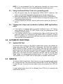
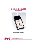
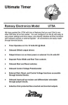
GROUND STRAP TESTER
Model 253A
Operating Instructions
4/09
1.0 APPLICATIONS
The Model 253A Ground Strap Tester shown in Figure 1.0-1 is a precision wall or bench
mounted test instrument that can test virtually all types of personnel grounding
cable/wrist strap and heel strap assemblies. The instrument measures both ESD
grounding straps with a nominal resistance of 1 Megohm and ORDNANCE grounding
straps with a nominal resistance of 50 kOhms. It can be used to test a strap assembly
alone or a complete cable/wrist strap system while on the wrist of the user. The
grounded power supply used in the Model 253A enables heel straps attached to
personnel to be tested without any additional connections when used in conjunction with
grounded floor systems.
Figure 1.0-1: Model 253A Ground Strap Tester
2.0 EQUIPMENT DESCRIPTION
The Model 253A Ground Strap Tester is housed in a heavy-duty plastic housing
measuring 4.75” x 4.75” x 2” (121x121x51mm). The removable top cover is attached to
the base unit by four captive screws. A silicon rubber gasket provides additional
protection from outside contamination. The system is AC powered and incorporates a
built-in transformer coupled regulated power supply protected by a ¼ amp fuse. Either
115 or 230VAC operation can be specified. A heavy-duty 3-wire, 18 gauge, 8 foot long
power cord is provided.
3.0 SET-UP
The Model 253A is designed to be permanently mounted to a wall, but may also be
mounted to a workbench or be free standing. The unit contains four mounting holes that
will accept up to a #8 (4mm) size screw (not supplied unless a specific type is specified
and ordered separately) The type of screw and its length will depend upon the surface
to which the unit is mounted. For wood walls, a 3/4” (20mm) long wood screw is
recommended. For plaster or dry wall, either a toggle bolt or a plastic anchor should be
used. For concrete walls, a plastic or lead anchor is recommended.
1
The hole pattern required is shown in Figure 3.0-1. It is recommended that the holes in
the base unit be used to locate the actual location of the holes.
To gain access to the mounting holes remove the front cover by unscrewing the four
captive screws. Carefully lift the cover and if necessary, disconnect the ribbon cable
from the selector switch PC Board.
CAUTION:
Disconnect the power cord whenever the front cover is removed.
115 or 240 VAC INSIDE.
Locate the mounting holes on the wall using the base as a template and then mount the
Model 253A using the appropriate screws.
Reconnect the ribbon cables. The connector is polarized. It can only fit into the mating
connector one way. The notch on the connector locks into a groove on the plastic
overhang of the PCB connector as shown in Figure 3.0-2.
3.55”
90mm
4.33”
110mm
Figure 3.0-1: Location of mounting holes
Figure 3.0-2: Interconnect cables
2
Carefully replace the front cover. Make certain that the interconnect cable does not
interfere with the pushbutton. When tightening the captive screws, apply equal torque.
Do not over tighten since this will distort the rubber gasket.
4.0 OPERATION
4.1
Testing cable and wrist strap only
a. Place STRAP SELECT Switch in the appropriate (ESD or ORD) STRAP
ONLY position.
b. Connect the grounding end of the cable to the appropriate mating banana
jack or snap located on the front of the unit. If the strap has a clip connection,
attach the clip to one of the snaps.
c. Touch the main grounding point on the strap to the Push-To-Test Button and
then depress the button.
d. If the cable/wrist strap assembly resistance is between the specified limits
(assembly good), the Red FAIL Light will flash and the beeper will sound
momentarily, then the Green PASS LED will light continuously indicating the
strap is good.
e. If the assembly resistance is below (shorted or low resistance) or above (high
resistance or broken resistor, wire or connection) the specified limits, the Red
FAIL light will continue to flash on and off and the beeper will continue to
sound indicating a defective cable/wrist strap assembly.
f. The cable or wrist strap portion of the assembly that contains the limiting
resistor can be tested separately by following the procedure in “a” to “e”
above.
4.2
Testing cable/wrist assembly on wearer’s wrist
a. Place the STRAP SELECT Switch in the appropriate (ESD or ORD) STRAP &
WEARER position.
b. Connect the grounding end of the cable to the appropriate mating banana
jack or snap located on the front of the unit. If clip connection is used, attach
the clip to one of the snaps. Attach the strap to the wrist in a normal manner.
c. Depress the PUSH TO TEST button and observe the PASS/FAIL indicators.
d. If the total system resistance (cable/strap/wearer) is within the specified limits
(system good), the Red FAIL light will flash and the beeper will sound
momentarily, then the Green PASS LED will light continuously, indicating that
the Cable/Strap/Wearer system is good.
e. If the total system resistance is below (shorted resistor) or above (broken
resistor and/or wire, open connection or poor contact between the strap and
wearer) the specified limits, the Red FAIL light will continue to flash on and off
and the beeper will continue to sound, indicating a defective
cable/strap/wearer system.
f. If the cable/strap/wearer system fails, check the cable/strap assembly alone
as described in Section 4.1 above. If the cable/strap assembly checks good,
the problem is poor contact resistance between the wearer and the wrist strap
assembly. The wearer may have to apply a lotion to the skin to improve
contact.
3
NOTE: It is recommended that the cable/strap assembly be tested alone
(Procedure 1 above) even if the cable/strap/wearer system tests good.
4.3
Using the Ground Strap Tester as a grounding point
a. Plug the ground strap into the appropriate STRAP INPUT connector. The
strap is now grounded through the third wire ground in the power cord.
b. Select the appropriate STRAP & WEARER function (ESD or ORDNANCE).
c. Periodically depress the PUSH TO TEST Button to check the integrity of the
cable/strap/wearer resistance.
d. If a FAIL indicator is activated, test the cable and/or strap as per Section 4.1
above.
4.4
Testing heel straps and conductive footwear (ESD applications
only):
a. If the facility is equipped with a grounded conductive floor (<105 Ohms),
simply depress the PUSH TO TEST Button to test the effectiveness of the
footwear grounding system.
b. If the location does not have a conductive floor, then a metal plate that the
user must stand on is connected to the STRAP INPUT connector. (Contact
ETS for installation of a convenient additional input jack located at the bottom
of the unit next to the power cord.)
5.0 AUTOMATIC FUNCTIONS
5.1
System Self-Test
The Model 253A contains a FAIL-SAFE measurement system that checks the
Tester each time the TEST BUTTON is depressed. The Red FAIL indicator
MUST ALWAYS FLASH (at least for an instant) each time the Test Button is
pushed even if the cable and wrist strap being tested is good. Should the Ground
Strap Tester fail to give this indication (even if it shows a PASS indication) a
malfunction in the Tester should be suspected. DO NOT USE the Ground Strap
Tester unless it is functioning as described herein. If in doubt, contact ElectroTech systems, Inc. at 215-887-2196 so that repairs, if required, can be made.
6.0 SERVICE
The Model 253A Ground Strap Tester contains no user serviceable parts except
the ¼ amp 3AG fuse. The fuse should be replaced ONLY WITH AN IDENTICAL
¼ amp 3AG type. If the new fuse also blows, return the complete unit to ETS for
repair.
A repair authorization must first be obtained from ETS prior to returning the
instrument for service.
4
7.0 CALIBRATION
The Model 253A calibration may easily be checked by the user by connecting standard
1% resistors, whose values are listed below, between the input connector and the
pushbutton.
7.1
ESD Mode
SWITCH POSITION
Lower Limit – Both Strap Only + Strap & Wearer:
(Nominal is 750K ± 5%)
Upper Limit – Strap Only:
(Nominal is 1.25M ± 5%)
Upper Limit – Strap + Wearer:
(Nominal is 10M ± 5%)
7.2
MUST FAIL
MUST PASS
<712.5K
>787.5K
>1.3125M
<1.1875M
>10.5M
<9.5M
MUST FAIL
MUST PASS
<43.65K
>46.35K
>56.65K
<53.35K
>1.03M
<970K
ORD Mode
SWITCH POSITION
Lower Limit – Both Strap Only + Strap & Wearer:
(Nominal is 45K ± 3%)
Upper Limit – Strap Only:
(Nominal is 55K ± 3%)
Upper Limit – Strap & Wearer:
(Nominal is 1M ± 3%)
(The above specifications are calculated. Tolerance on resistors used in ETS test
fixtures is 1%)
If the unit does not meet specification it should be returned to Electro-Tech
Systems for repair or recalibration.
Custom units with other resistance limits can be tested by selecting 1% resistors
whose values are within 3% of either side of the nominal limits specified.
4/09
5
4.0 WARRANTY
Electro-Tech Systems, Inc. warrants its equipment, accessories and parts of its
manufacture to be and remain free from defects in material and workmanship for a
period of one (1) year from date of invoice. It will, at it’s discretion, either replace or
repair without charge, F.O.B. Glenside, similar equipment or a similar part to replace
any equipment or part of its manufacture which, within the above stated time, is proved
to have been defective at the time it was sold. All equipment claimed defective must be
returned properly identified to the Seller (or presented to one of its agents for
inspection). This warranty only applies to equipment operated in accordance with
Seller's operating instructions.
Seller's warranty with respect to those parts of the equipment that are purchased from
other manufacturers shall be subject only to that manufacturer's warranty.
The Seller's liability hereunder is expressly limited to repairing or replacing any parts of
the equipment manufactured by the manufacturer and found to have been defective.
The Seller shall not be liable for damage resulting or claimed to result from any cause
whatsoever.
This warranty becomes null and void should the equipment, or any part thereof, be
abused or modified by the customer of if used in any application other than that for
which it was intended. This warranty to replace or repair is the only warranty, either
expressed or implied or provided by law and is in lieu of all other warranties. The Seller
denies any other promise, guarantee or warranty with respect to the equipment or
accessories. In particular, as to its or their suitability for the purposes of the buyer or its
or their performance, either quantitatively or qualitatively or as to the products that it
may produce and the buyer is expected to expressly waive rights to any warranty other
than that stated herein.
ETS must be notified before any equipment is returned for repair. ETS will issue an
RMA (Return Material Authorization) number for return of equipment.
Equipment should be shipped prepaid and insured in the original packaging. If the
original packaging is not available, the equipment must be packed in a sufficiently large
box (or boxes if applicable) of double wall construction with substantial packing around
all sides. The RMA number, description of the problem along with the contact name and
telephone number must be included in formal paperwork and enclosed with the
instrument. Round trip freight and related charges are the owner’s responsibility.
6