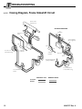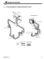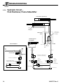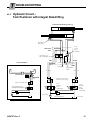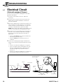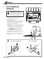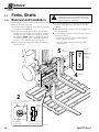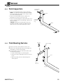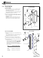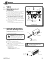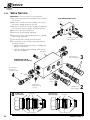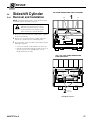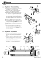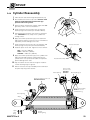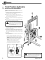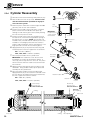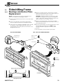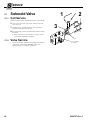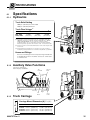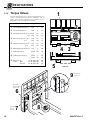
1
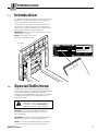
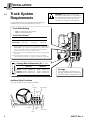
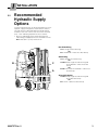
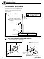
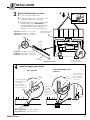
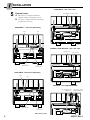
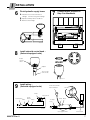
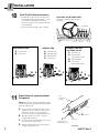
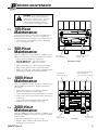
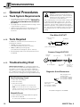
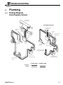
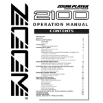
S
ERVICE MANUAL
C-Series
Fork Positioner
Manual Number 6009757
cascade姞
Cascade is a Registered Trademark of Cascade Corporation
C
ONTENTS
C-Series Fork Positioner
Page
Page
INTRODUCTION, Section 1
Introduction, 1.1
Special Definitions, 1.2
INSTALLATION, Section 2
Truck System Requirements, 2.1
Recommended Hydraulic Supply Options, 2.2
Fork Positioner Installation Procedure, 2.3
PERIOD MAINTENANCE, Section 3
100-Hour Maintenance, 3.1
500-Hour Maintenance, 3.2
1000-Hour Maintenance, 3.3
2000-Hour Maintenance, 3.4
TROUBLESHOOTING, Section 4
General Procedures, 4.1
Truck System Requirements, 4.1-1
Tools Required, 4.1-2
Troubleshooting Chart, 4.1-3
Plumbing, 4.2
Hosing Diagram,Fork Position Circuit, 4.2-1
Hosing Diagram, Sideshift Circuit, 4.2-2, 4.2-3
Hydraulic Circuit, 4.2-4, 4.2-5
Fork Position Function, 4.3
Supply Circuit Test, 4.3-1
Fork Circuit Test, 4.3-2
Valve Test, 4.3-3
Cylinder Test, 4.3-4
Sideshift Function, 4.4
Supply Circuit Test, 4.4-1
Sideshift Cylinder Test, 4.4-2
Sideshifting Valve Test, 4.4-3
Electrical Circuit, 4.5
i
1
1
2
3
4
9
9
9
9
10
10
10
10
11
11
12
14
16
16
16
17
17
18
18
18
19
20
SERVICE, Section 5
Fork Positioner Removal, 5.1
Forks, Shafts, 5.2
Removal and Installation, 5.2-1
Fork Inspection, 5.2-2
Fork Bearing Service, 5.2-3
Fork Carrier, 5.2-4
Valve, 5.3
Valve Removal, Installation, 5.3-1
Eliminating Regeneration Circuit, 5.3-2
Valve Service, 5.3-3
Sideshift Cylinder, 5.4
Cylinder Removal, Installation, 5.4-1
Cylinder Disassembly, 5.4-2
Cylinder Inspection, 5.4-3
Cylinder Reassembly, 5.4-4
Fork Position Cylinders, 5.5
Cylinder Removal, Installation, 5.5-1
Cylinder Disassembly, 5.5-2
Cylinder Inspection, 5.5-3
Cylinder Reassembly, 5.5-4
Sideshifter Frame, 5.6
Bearings, Anchor Plate Replacement, 5.6-1
Solenoid Valve, 5.7
Coil Service, 5.7-1
Valve Service, 5.7-2
SPECIFICATIONS, Section 6
Specifications, 6.1
Hydraulics, 6.1-1
Auxiliary Valve Functions, 6.1-2
Truck Carriage, 6.1-3
Torque Values, 6.1-4
21
22
22
23
23
24
25
25
25
26
27
27
28
28
29
30
30
31
31
32
33
33
34
34
34
35
35
35
35
36
6009757 Rev. 0
I
1.1
NTRODUCTION
Introduction
This Manual provides the Installation Instructions, Periodic
Maintenance, Troubleshooting, Service and Specifications for Cascade C-Series Fork Positioners.
In any communication about the Fork Positioner, refer to
the product I.D. number stamped on the nameplate as
shown. If the nameplate is missing, the numbers can be
found stamped on the back of the baseplate.
IMPORTANT: All hoses, tubes and fittings on C-Series
Fork Positioners are JIC.
NOTE: Specifications are shown
in both U.S. and (Metric) units.
Nameplate
c
SERIAL
NUMBER
CATALOG
NUMBER
cascade姞
LIFT TRUCK ATTACHMENT
221550
55C-FPB-01A
WEIGHT
LBS.
ATTACHMENT CAPACITY
POUNDS
INCH LOAD
AT
CENTER
CAPACITY OF TRUCK AND ATTACHMENT COMBINATION
MAY BE LESS THAN ATTACHMENT CAPACITY SHOWN
ABOVE. CONSULT TRUCK NAMEPLATE.
RECOMMENDED SYSTEM PRESSURE – 2000 PSI
MAXIMUM SYSTEM PRESSURE – 2300 PSI
ADDITIONAL
EQUIPMENT
cascade姞 corporation
ADDITIONAL
EQUIPMENT
FOR TECHNICAL
ASSISTANCE, CONTACT
800-227–2233
PORTLAND, OREGON USA
ADDITIONAL
EQUIPMENT
FOR PARTS AND SERVICE
MANUALS, CONTACT
800-227–2233
SPRINGFIELD, OHIO USA
50
FP0328.ill
1.2
S/N
15
22
Special Definitions
The statements shown appear throughout this Manual
where special emphasis is required. Read all WARNINGS
and CAUTIONS before proceeding with any work.
Statements labeled IMPORTANT and NOTE are provided
as additional information of special significance or to
make the job easier.
WARNING - A statement preceded by
WARNING is information that should be
acted upon to prevent bodily injury. A
WARNING is always inside a ruled box.
CAUTION - A statement preceded by CAUTION is
information that should be acted upon to prevent
machine damage.
IMPORTANT - A statement preceded by IMPORTANT is
information that possesses special significance.
NOTE - A statement preceded by NOTE is information
that is handy to know and may make the job easier.
6009757 Rev. 0
1
I
2.1
NSTALLATION
Truck System
Requirements
WARNING: Rated capacity of the truck/
attachment combination is a responsibility of
the original truck manufacturer and may be
less than that shown on the attachment
nameplate. Consult the truck nameplate.
C-Series Fork Positioners will provide maximum operating
capability when the following requirements are met.
Truck Relief Setting
2000 psi (140 bar) Recommended
2300 psi (160 bar) Maximum
Truck Flow Volume ➀
55C, 100C,
120C, 150C
Min. ➁
Recommended
Max. ➂
5 GPM
(19 L/min.)
7 GPM
(26 L/min.)
10 GPM
(38 L/min.)
➀ Cascade C-Series Fork Positioners are compatible with SAE 10W
petroleum base hydraulic fluid meeting Mil. Spec. MIL-0-5606 or
MIL-0-2104B. Use of synthetic or aqueous base hydraulic fluid is
not recommended. If fire resistant hydraulic fluid is required,
special seals must be used. Contact Cascade.
➁ Flow less than recommended will result in slow and unequal fork
movement.
➂ Flow greater than maximum can result in excessive heating,
reduced system performance and reduced hydraulic system life.
GA0080.ill
Carriage Mount Dimension (A) ITA (ISO)
Minimum
Maximum
A
Class II 14.96 in. (380.0 mm)
Class III 18.68 in. (474.5 mm)
Class IV 23.44 in. (595.5 mm)
15.00 in. (381.0 mm)
18.74 in. (476.0 mm)
23.50 in. (597.0 mm)
GA0028.ill
Carriage
Clean and inspect carriage bars for
damage and smoothness. Repair any
protruding welds or damaged notches.
Auxiliary Valve Functions
Check for compliance with ITA (ISO) standards:
Tilt
Forward
Hoist Down
GA0082.ill
Hoist Up
Tilt
Back
2
Spread Forks
Sideshift
Left
Sideshift
Right
Close Forks
6009757 Rev 0
I
NSTALLATION
Recommended
Hydraulic Supply
Options
2.2
C-Series Fork Positioners can be operated with any of the
hydraulic supply arrangements shown below. Refer to
Cascade Hose & Cable Reel Selection Guide, Part No.
212199, to select the correct hose reel for the mast and
truck. Hose and fitting requirements are as follows:
• All hoses and fittings for the fork-positioning and
sideshifting (if equipped) functions should be at least
No. 6 with 9/32 in. (7 mm) minimum I.D.
Non-Sideshifting
A Mast Single Internal Reeving
OR
B RH THINLINE姠 2-Port Hose Reel Group
Sideshifting
B
C
A
A Mast Double Internal Reeving
OR
A and B Mast Single Internal Reeving and
RH THINLINE姠 2-Port Hose Reel
Group
OR
B and C RH and LH THINLINE姠 2-Port Hose
Reel Groups
Solenoid Adaption
A and B Mast Single Internal Reeving and
RH Cable Reel Group
OR
B RH 6-N-1 Cable/Hose Reel Group
GA0033.ill
6009757 Rev. 0
3
I
2.3
NSTALLATION
Installation Procedure
Follow the steps shown to install the Fork Positioner on the
truck. Read and understand all WARNING and CAUTION
statements. If you don't understand a procedure, ask your
supervisor, or call the nearest Cascade Service Department for assistance.
Attach overhead hoist
A Remove banding.
B Attach hoist to top of backrest as
1
shown and lift Attachment into vertical
position on pallet. Use wood blocking
as required to stabilize Attachment.
C
WARNING: Make sure overhead
hoist has a rated capacity of at
least 2000 lbs. (910 kg.)
B
Remove bolt-on lower mounting hooks
(if equipped).
B
Bolt-On
Lower
Hooks
C
Wood Blocking
FP0202.ill
2
Unlock Quick-Change lower mounting hooks (if equipped)
A Remove pin and drop hooks into unlocked position.
B Re-install pin in lower hole.
NOTE: Guides can be reversed to
reduce hook-to-carriage clearance
(See lower hook installation, Step 6).
A
Guide
®
de
ca
s
ca
C-
B
67
55
14
-1
LH lower
Hook
5/8-in. (16 mm)
offset on top
provides max.
clearance.
CL0097.ill
Pin
Tighten Capscrews:
Class II / III Mounting – 165 ft.-lbs. (225 Nm)
Class IV Mounting – 190 ft.-lbs. (255 Nm)
4
6009757 Rev 0
I
NSTALLATION
3
B
Mount Fork Positioner on truck
A Center truck behind Attachment.
B Hang Attachment onto truck carriage, or raise
B
carriage into upper hooks (see inset).
FP0366.ill
C
Engage upper mounting hooks or sideshifting
full-length upper hook. IMPORTANT: If
sideshifter equipped, assure upper bearings
are installed properly and centering tab
engages center notch on truck carriage bar.
Sideshifting full-length
upper hook shown
ITA Class II – 0.60–0.66 in. (15–17 mm)
ITA Class III – 0.72–0.78 in. (18–20 mm)
ITA Class IV – 0.72–0.78 in. (18–20 mm)
C
Center
Notch
C
ITA Class II – 0.32–0.36 in. (8–9 mm)
ITA Class III – 0.39–0.43 in. (10–11 mm)
ITA Class IV – 0.47–0.51 in. (12–13 mm)
FP0213.ill
Truck
Carriage
SD0023.ill
SS0139.ill
Sideshifter Upper
Bearings (if equipped)
Back (Driver's) View
4
Install or engage lower hooks
QUICK-DISCONNECT TYPE
(optional)
BOLT-ON TYPE
Tap tight into position.
If sideshifter, back off
1 notch and
check clearance:
3/32 in. (2.4 mm) min.
3/16 in. (4.8 mm) max.
Lower
Carriage
Bar
ST
JU
AD
SS0140.ill
Lower
Carriage
Bar
Inspect hooks for
excessive clearance.
(Reverse guides to
reduce clearance –
see Step 2.)
®
Slide hook up
to engage
bar, install
pin in locked
position.
(upper hole.)
c
c
as
C-
67
ad
55
14
e
-1
3/16 in.
(4.8 mm)
max.
SS0141.ill
Tighten Capscrews:
Class II, III Mounting – 165 ft.-lbs. (225 Nm)
Class IV Mounting – 190 ft.-lbs. (255 Nm)
6009757 Rev. 0
5
I
NSTALLATION
HOSE REELS – 100C, 120C, 150C
5
Prepare hoses
A Determine hose lengths required for
Spread Forks
Close Forks
hydraulic supply configuration of truck.
B
Cut hoses to length and install end fittings
or quick-disconnect kits.
HOSE REELS – 55C Frame Sideshifting
SSR
SSL
SSR
SSL
FP0367.ill
INTERNAL HOSE REEVING – 100C, 120C, 150C
Spread Forks
FP0221.ill
Close Forks
Spread Forks
Close Forks
HOSE REELS – 55C Internal Sideshifting
SSR
SSL
SSR
SSL
FP0200.ill
SOLENOID – 6-N-1 CABLE/HOSE REEL
SSL / Spread Forks
(TANK port)
FP0349.ill
SSR / Close Forks
(PRESSURE port)
Spread Forks
Close Forks
Back (Driver's) Views
6
FP0199.ill
6009757 Rev 0
I
NSTALLATION
6
Flush hydraulic supply hoses
A Install hoses to hose terminals on
carriage. Connect using union fittings.
B
C
7
Connect hoses prepared in
Step 5 to Attachment
Operate auxiliary valves for 30 sec.
Remove union fittings.
GA0092.ill
FP0214.ill
8
Install solenoid control knob –
(Solenoid-equipped units)
PRESS
BUTTON
TO POSITION
Button
toward
driver
SIDESHIFT
Adapter
Truck control
valve handle
FP0320.ill
9
Install wiring –
(Solenoid-equipped units)
Diode
7.5-Amp Fuse
White
Control Lever Knob
with Pushbutton
Diode
Solenoid Coil
Knob
Button
7.5-Amp
Fuse
Black
CL0258.ill
White Black
CL0257.ill
User-supplied wire
Solenoid Coil
Solenoid Coil
6009757 Rev. 0
7
I
NSTALLATION
10
Cycle Fork Positioner functions
AUXILIARY VALVE FUNCTIONS
• Spread forks and close forks several times.
Sideshift (if equipped) left and right. Check
for smoothness and equal movement.
Check for compliance with ITA (ISO)
standards:
• Check for operation in accordance with ITA
(ISO) standards.
Hoist down
• Check for leaks at fittings, valve, cylinders.
Tilt forward
A C
B
D
GA0005.ill
Hoist up
SIDESHIFTING
NON-SIDESHIFTING
A
B
A
B
C
D
Spread Forks
Close Forks
B
FP0204.ill
A
11
SIDESHIFTING WITH
SOLENOID VALVE
Sideshift Left
A
A
Sideshift Right
Spread Forks
Close Forks
B
B
Sideshift Left
Spread Forks
(press knob button)
Sideshift Right
Close Forks
(press knob button)
A
B
B
Tilt back
D C
B
A
D
C
B A
FP0204.ill
B
Adjust forks for equal movement
(if required)
A
FP0204.ill
A
Fork
Positioning
Cylinder
NOTE: Attachment is Factory-adjusted for equal
fork movement when operated at recommended
pressure and flow rate.
FP0194.ill
8
A
Locate cylinder 'T' fittings with flow restrictor
adjustment. Loosen jam nuts and screw
both flow restrictors in until they bottom.
Screw each restrictor out (CCW) three turns.
B
Spread forks fully, then close. Look for
unequal fork movement.
C
On faster fork (one that bottoms first), screw
flow restrictor in (CW) 1/2-turn.
D
Repeat Steps B and C until fork movement
is equal. Tighten jam nuts.
A
C
'T' fitting
Jam Nut
Flow Restrictor
Adjustment Screw
Front View
6009757 Rev 0
P
T
ERIODIC
MAINTENANCE
ROUBLESHOOTING
WARNING: After completing any service
procedure, always test each function
through five complete cycles. First test
with no load, then test with a load to
make sure the attachment operates
correctly before returning it to the job.
3.1
100-Hour
Maintenance
Every time the lift truck is serviced or every 100 hours of
truck operation, whichever comes first, complete the
following maintenance procedures on the Fork Positioner:
• Check for loose or missing bolts, worn or damaged
hoses and hydraulic leaks.
3.2
500-Hour
Maintenance
After each 500 hours of truck operation, in addition to the
100-hour maintenance, perform the following procedures:
FP0215.ill
Sideshifter
Lower Bearings (2)
Lower Mounting Hook
Capscrews (4)
• Tighten lower mounting hook capscrews:
Back (Driver's) View
Class II, III Mounting – 165 ft.-lbs. (225 Nm)
Class IV Mounting – 190 ft.-lbs. (255 Nm)
• Apply chassis grease to fork bearing grease fittings.
• Apply chassis grease to fork cylinder rod anchors.
• Apply chassis grease to sideshifter (if equipped) upper
bearing grease fittings and lower flat bearings.
Fork Bearing
Grease Fittings (4)
3.3
Sideshifter Upper Bearing
Grease Fittings (2)
(sideshift to expose fittings)
1000-Hour
Maintenance
After each 1000 hours of truck operation, in addition to the
100 and 500-hour maintenance, perform the following
procedures:
• Inspect forks for wear. Cascade Fork Safety Kit
3014162 is available for this procedure.
• Inspect fork bearings for wear and replace if necessary.
• Inspect fork cylinder rod anchors for wear and replace
if necessary.
• Inspect sideshifter (if equipped) upper and lower
bearings for wear and replace if necessary.
3.4
2000-Hour
Maintenance
After each 2000 hours of truck operation, in addition to the
100, 500 and 1000-hour maintenance, perform the following procedures:
• Replace fork bearings (see Section 5.2-3).
FP0201.ill
Fork
Bearings (4)
Front View
Cylinder Rod
Anchors (2)
• Replace upper and lower sideshifter bearings (if
equipped). See Section 5.6.
6009757 Rev. 0
9
T
ROUBLESHOOTING
4.1
General Procedures
4.1-1
Truck System Requirements
• Truck hydraulic pressure should be within the range
shown in Specifications, Section 6.1. PRESSURE TO
THE FORK POSITIONER MUST NOT EXCEED 2300
psi (160 bar).
• Truck hydraulic flow should be within the range shown
in Specifications, Section 6.1.
• Hydraulic fluid supplied to the Fork Positioner must
meet the requirements shown in Specifications,
Section 6.1.
WARNING: Before servicing any
hydraulic component, relieve pressure in
the Attachment system. Turn the truck off
and move the truck auxiliary control lever
several times in both directions.
After completing any service procedure, always test
the Attachment through several cycles. First test
empty to bleed any air trapped in the system to the
truck tank. Then test with a load to assure that the
Attachment operates correctly before returning to the
job. Stay clear of the load while testing. Do not raise
the load more than 4 in. (10 cm) off the floor while
testing.
Flow Meter Kit 671477
4.1-2
Tools Required
(2) No. 8-12 JIC/
O-Ring
Flow Meter
In addition to a normal selection of hand tools, the
following are required:
• 20 GPM (75 L/min) inline flow meter.
(Cascade Flow Meter Kit, part no. 671477.)
GA0013.ill
(2) No. 6-8 JIC Reducer
• 3000 psi (200 bar) pressure gauge.
(Cascade Pressure Gauge Kit, part no. 671212.)
• Assorted fittings, drain hoses and quick-disconnects
as required.
Pressure Gauge Kit 671212
Pressure
Gauge*
4.1-3
GA0014.ill
Troubleshooting Chart
No. 4-6 Pipe/JIC*
Determine All The Facts – It is important to gather all
the facts about the problem before beginning any service
procedures. The first step is to talk to the equipment
operator. Ask for a complete description of the malfunction. Guidelines below and on the following pages can
then be used as a starting point to begin troubleshooting.
To correct these problems, see Section 4.3.
NOTE: Some Fork Positioners have a regenerative
hydraulic circuit that causes the forks to open at a faster
speed than when closing. This is a normal function.
No. 4, No. 6*
and No. 8
JIC/O-Ring
Male Straight Thread
O-Ring Coupler:
No. 4 (Part No. 212282)*
No. 5 (Part No. 210378)
No. 6 (Part No. 678592)
• Forks have uneven travel.
• Forks will not move.
No. 6-8 JIC
Reducer
Diagnostic Quick-Disconnects
Fork Positioning Circuit
• Forks move slowly.
No. 6 and No. 8
JIC Swivel Tee
No. 6-6 Hose*
Female JIC Thread
QD Coupler:
No. 4 (Part No. 210385)*
No. 6 (Part No. 678591)
AC0127.ill
* included in Diagnostics Kit 394382.
Sideshift Circuit
• Forks sideshift left and right at different speeds.
• Forks will not sideshift.
To correct these problems, see Section 4.4.
10
6009757 Rev. 0
T
4.2
4.2-1
ROUBLESHOOTING
Plumbing
Hosing Diagram,
Fork Position Circuit
Fork Position
Cylinders (2)
SOLENOID ADAPTION
To Fork Position
Cylinders
Attachment
Valve
OPEN
Port
Solenoid Valve
(Energized)
OPEN
Port
Sideshift
Cylinder
CLOSE
Port
Sideshift
Cylinder
CLOSE
Port
P Port
T Port
Truck Auxiliary Valve
(with pushbutton)
FP0322.ill
Hose Reel or
Internal Reeving
Hose/Cable Reel
or Internal Reeving
Truck Auxiliary
Valves
CLOSE FORKS
SPREAD FORKS
Pressure:
Return:
6009757 Rev. 0
11
T
4.2-2
ROUBLESHOOTING
Hosing Diagram, Frame Sideshift Circuit
Fork Position
Cylinders (2)
SOLENOID ADAPTION
To
Cylinders
Attachment
Valve
Solenoid Valve
(De-energized)
SSR
SSR
SSL
SSL
Hose Reel or
Internal Reeving
Sideshift
Cylinder
Sideshift
Cylinder
P Port
T Port
Truck Auxiliary Valve
(with pushbutton)
FP0323.ill
Hose/Cable Reel
or Internal Reeving
Truck Auxiliary
Valves
SIDESHIFT LEFT
SIDESHIFT RIGHT
Pressure:
Return:
12
6009757 Rev. 0
T
4.2-3
ROUBLESHOOTING
Hosing Diagram, Integral Sideshift Circuit
Fork Position
Cylinders (2)
SOLENOID ADAPTION
To
Cylinders
SSL
Solenoid Valve
(De-energized)
SSL
Attachment
Valve
SSR
SSR
Hose Reel or
Internal Reeving
P Port
T Port
Truck Auxiliary Valve
(with pushbutton)
FP0352.ill
Hose/Cable Reel
or Internal Reeving
Truck Auxiliary
Valves
SIDESHIFT LEFT
SIDESHIFT RIGHT
Pressure:
Return:
Slave:
6009757 Rev. 0
13
T
4.2-4
ROUBLESHOOTING
Hydraulic Circuit –
Fork Positioner, Frame Sideshifter
Fork Position Cylinders (2)
Flow
Restrictor
Fittings (2)
Forks Close
Check Valve
Cartridge
Attachment
Valve
Sideshift Cylinder
(if equipped)
Solenoid Adaption
Restrictor
Washer
Test Port G
OPEN
CLOSE
Regeneration
Valve
Solenoid Valve
TANK
Port
PRESSURE
Port
2-Port Hose Reels (2) or
Internal Hose Reeving
2-Port Hose/Cable Reel
Truck
Auxiliary
Valve
(SIDESHIFT)
Truck Auxiliary Valve
(SIDESHIFT/POSITION)
Truck
Auxiliary
Valve
(FORK
POSITION)
Truck Pump
Truck Relief Valve
Truck Tank
CL1046.ill
FP0324.ill
14
6009757 Rev. 0
T
4.2-5
ROUBLESHOOTING
Hydraulic Circuit –
Fork Positioner with Integral Sideshifting
Fork Position/Sideshift Cylinders (2)
Flow Restrictor
Fittings (2)
Close
Check
Valve
Cartridge
Attachment
Valve
Sideshift Check
Valve Cartridges (2)
SSR
CLOSE
Solenoid Adaption
SSL
Test Port G
OPEN
Regeneration
Valve
Solenoid Valve
TANK
Port
PRESSURE
Port
2-Port Hose Reels (2) or
Internal Hose Reeving
2-Port Hose/Cable Reel
Truck
Auxiliary
Valve
(SIDESHIFT)
Truck Auxiliary Valve
(SIDESHIFT/POSITION)
Truck
Auxiliary
Valve
(FORK
POSITION)
Truck Pump
Truck Relief Valve
Truck Tank
CL1046.ill
FP0353.ill
6009757 Rev. 0
15
T
4.3
ROUBLESHOOTING
Fork Position
Function
There are six potential problems that could affect the FORK
POSITION function:
WARNING: Before removing hydraulic
lines or components, relieve pressure in the
Attachment hydraulic system. Turn the
truck off and move the auxiliary control
lever several times in both directions.
• Damaged or bent frame.
Flow Meter
• Incorrect load handling. Refer to Operator’s Guide for
suggested procedures.
2
• Incorrect hydraulic pressure or flow from the lift truck.
• External leaks.
• Defective solenoid coil or valve (if equipped).
• Worn or defective cartridge valves or cylinder seals.
4.3-1
4.3-2
Supply Circuit Test
1
Check the pressure supplied by the truck at the carriage
hose terminal. Pressure must be within the range shown
in Specifications, Section 6.1. PRESSURE TO THE
FORK POSITIONER MUST NOT EXCEED 2300 PSI
(160 bar).
2
Check the flow volume at the carriage hose terminal.
Flow must be within the range shown in Specifications,
Section 6.1.
3
Close the forks fully, holding the lever in the CLOSE
position for a few seconds. Release the lever and check
for external leaks at fittings, hoses, valve and manifold.
Fork Circuit Test
1
Press the solenoid button (if equipped) and listen for a
'click' at the solenoid valve. If no sound is heard, first
check the fuse, wiring and coil (see Section 4.5). Assure
that the valve is not jammed (see Section 5.7).
FP0325.ill
Pressure Gauge
on test port 'G'
2
IMPORTANT: Solenoid-operated valves must be
plumbed so that the solenoid is energized during the
FORK POSITION function.
2
Position the forks to mid-stroke. Turn the truck off and
connect a 3000 psi (200 bar) pressure gauge to the 'G'
test port on the back of the main valve.
3
Start the truck and close the forks fully, holding the lever
in the CLOSE position for a few seconds.
4
Release the lever and watch the pressure gauge:
• If the pressure drop is less than 150 psi (10 bar)
initially, and additional drop does not exceed 25 psi
(1.7 bar) per minute, the problem is not hydraulic (see
Section 4.3).
• If the pressure drop is more than 150 psi (10 bar)
initially, and additional drop exceeds 25 psi (1.7 bar)
per minute, Turn the truck off and proceed to Valve
Test, Section 4.3-3.
FP0326.ill
3
Back (Driver's) View
16
6009757 Rev. 0
T
4.3-3
ROUBLESHOOTING
Valve Test
1
Disconnect both hydraulic supply lines from the rod end
of the cylinders. Plug the lines and cap the ports.
2
Start the truck and hold the lever in the CLOSE position
for a few seconds.
3
Release the lever and watch the pressure gauge:
• If the pressure drop is more than 150 psi (10 bar)
initially, and additional drop exceeds 25 psi (1.7 bar)
per minute, the fork check valve cartridge in the main
valve is faulty and requires service (see Section 5.3).
• If the pressure drop is less than 150 psi (10 bar)
initially, and additional drop does not exceed 25 psi
(1.7 bar) per minute, one or both cylinders require
service. Turn the truck off and proceed to Cylinder
Test, Section 4.3-4.
FP0335.ill
1
Disconnect cylinder rod
end supply lines (plug
lines and cap ports).
4.3-4
Cylinder Test
1
Connect one (1) of the rod-end hydraulic lines to its
cylinder. IMPORTANT: The other line and cylinder port
must remain plugged.
2
Start the truck and hold the lever in the CLOSE position
for a few seconds.
3
Release the lever and watch the pressure gauge:
• If the pressure drop is more than 150 psi (10 bar)
initially, and additional drop exceeds 25 psi (1.7 bar)
per minute, the cylinder connected to the valve is
faulty and requires service (see Section 5.5).
• If the pressure drop is less than 150 psi (10 bar)
initially, and additional drop does not exceed 25 psi
(1.7 bar) per minute, the other cylinder is faulty and
requires service (see Section 5.5).
It is recommended that a similar pressure test be
performed on the other cylinder before servicing.
FP0336.ill
6009757 Rev. 0
1
Connect rod end
supply line to one
(1) cylinder.
17
T
4.4
ROUBLESHOOTING
Sideshift Function
WARNING: Before removing hydraulic
lines or components, relieve pressure in
the Attachment hydraulic system. Turn the
truck off and move the auxiliary control
valve lever several times in both directions.
The following potential problems could affect the
sideshifting function:
• Damaged or bent frame.
• Incorrect hydraulic pressure or flow from lift truck.
• External leaks.
• Defective solenoid coil or valve (if equipped).
• Worn or defective cartridge valves or cylinder seals.
• Flow restrictor fittings plugged or incorrectly adjusted.
(Frame-type sideshifter only)
• Inadequate upper bearing lubrication or worn bearings.
• Lower mounting hooks installed with incorrect clearance.
• Sideshift cylinder flow restrictor plugged or incorrectly
installed.
4.4-1
4.4-2
Supply Circuit Test
1
Check the pressure supplied by the truck at the carriage
hose terminal. Pressure must be within the range shown
in Specifications, Section 6.1. PRESSURE TO THE
ATTACHMENT MUST NOT EXCEED 2300 PSI (160 bar).
2
Check the flow volume at the carriage hose terminal.
Flow must be within the range shown in Specifications,
Section 6.1.
3
Sideshift fully left or right, holding the lever in the SIDESHIFT position for a few seconds. Release the lever and
check for external leaks at fittings, hoses, and cylinder
rod ends.
FP0327ill
2
Back (Driver's) View
Flow Meter
Sideshift Cylinder Test
1
Press the solenoid button (if equipped) and listen for a
'click' at the solenoid valve. If no sound is heard, first
check the fuse, wiring and coil (see Section 4.5). Assure
that the valve is not jammed (see Section 5.7).
IMPORTANT: Solenoid-operated valves must be
plumbed so that the solenoid is not energized during the
SIDESHIFT function.
2
3
Sideshift fully to the right. Turn the truck off and relieve
Attachment system pressure. Disconnect the SIDESHIFT
LEFT supply hose from the truck hose terminal and route
to a drain bucket. Cap the supply fitting.
Start the truck and actuate the SIDESHIFT RIGHT lever for
5 seconds:
Cap
Supply
Fitting
Sideshift LEFT Hose
• If there is substantial hydraulic flow out of the drain
hose, the sideshift cylinder seals are defective and
require service. Refer to Section 5.4.
• If there is no hydraulic flow out of the drain hose,
check for plugged or incorrectly-adjusted flow restrictor fittings. If there is still no hydraulic flow, the
problem is not hydraulic (see Section 4.4).
FP0338.ill
2
Hose end in
drain bucket.
Back (Driver's) View
18
6009757 Rev. 0
T
4.4-3
ROUBLESHOOTING
Sideshifting Valve Test
IMPORTANT: This procedure tests only for proper operation
of the sideshifting check valve cartridges. Perform the fork
position circuit test (see Section 4.3-2) to assure proper
cylinder operation.
Pressure Gauge
1
WARNING: Before removing hydraulic
lines or components, relieve pressure in
the Attachment hydraulic system. Turn the
truck off and move the auxiliary control
valve lever several times in both directions.
1
Install a 3000 psi (200 bar) pressure gauge in the valve
test port 'G', located on the back of the valve body.
2
Start the truck and actuate the SIDESHIFT LEFT lever for
5 seconds.
3
Return the control lever to neutral and watch the gauge:
• If the pressure drop is more than 150 psi (10 bar)
initially, and additional drop exceeds 25 psi (1.7 bar)
per minute, the sideshift left cartridge is faulty and
requires replacement or service (see Section 5.3-3).
• If the pressure drop is less than 150 psi (10 bar)
initially, and additional drop does not exceed 25 psi
(1.7 bar) per minute, actuate the SIDESHIFT RIGHT
lever for 5 seconds.
4
FP0350.ill
2
Return the control lever to neutral and watch the gauge:
• If the pressure drop is more than 150 psi (10 bar)
initially, and additional drop exceeds 25 psi (1.7 bar)
per minute, the sideshift right cartridge is faulty and
requires replacement or service (see Section 5.3-3).
Back (Driver's) View
• If the pressure drop is less than 150 psi (10 bar)
initially, and additional drop does not exceed 25 psi
(1.7 bar) per minute, the problem is not hydraulic (see
Section 4.4).
6009757 Rev. 0
19
T
4.5
ROUBLESHOOTING
Electrical Circuit
(Solenoid-equipped Clamps)
Use the electrical schematic and diagram shown and
follow the steps below:
1
Check the control knob circuit fuse. Replace if
necessary.
2
Check for loose electrical connections at the truck
ignition switch, control knob button, solenoid coil
terminals and diode.
3
Remove the diode from the solenoid coil terminal. Test
with an ohmmeter for high resistance in one direction
and no resistance in the other direction. If there is no
resistance in both directions, replace the diode.
NOTE: When replacing the diode, the banded (+) end
must be connected to the coil and wiring as shown.
4
Disconnect the electrical leads from the solenoid coil
terminals. Use a voltmeter to determine if voltage is
present at the electrical leads when the button is
depressed.
• If there is no current to the solenoid, troubleshoot
the electrical circuit for shorts.
• If there is current to the solenoid, test for coil
continuity.
5
Test for coil continuity by placing an ohmmeter test
lead on each solenoid coil terminal (ohmmeter on Rx1
scale).
• If there is an ohmmeter reading, the coil is good.
• If the coil is good, but the solenoid does not 'click'
when the control knob button is depressed, the
solenoid cartridge may be jammed. Refer to
Section 5.7.
• If there is no ohmmeter reading, the coil is defective
and should be replaced. Refer to Section 5.7.
Control Lever Knob
with Pushbutton
Diode
7.5-Amp Fuse
White
Diode
Solenoid Coil
Knob
Button
7.5-Amp
Fuse
Black
CL0258.ill
White Black
CL0257.ill
User-supplied wire
Solenoid Coil
Solenoid Coil
20
6009757 Rev. 0
S
5.1
ERVICE
Open
Fork Positioner
Removal
1
Close
Position the forks to the width of the frame.
WARNING: Before removing hydraulic
lines or hoses, relieve pressure in the
Attachment hydraulic system. Turn the
truck off and move the auxiliary control
lever several times in both directions.
2
Disconnect and plug the hydraulic supply hoses to the
fork position cylinders and sideshifting cylinder (if
equipped). Tag hoses for reassembly.
3
Disconnect the lower hooks:
Quick-Change Hooks – Remove the locking pins and
drop the hooks into the unlocked position. Replace the
pins in the lower holes. For reassembly, remove the
pins and slide the hooks up to the locked position.
Replace the pins in the upper holes.
2
FP0198.ill
SSR
SSL
Back (driver's) View
Bolt-On Hooks – Remove the capscrews and mounting
hooks. For reassembly, tap hooks tight into position for
non-sideshifting frame. If sideshifting frame, back off 1
notch and check clearance: 3/32 in. (2.4 mm) min.,
3/16 in. (4.8 mm) max. Tighten capscrews as follows:
Class II/III Mounting – 165 ft.-lbs. (225 Nm).
Class IV Mounting – 190 ft.-lbs. (255 Nm).
4
Lower the Fork Positioner onto a pallet. Tilt the mast
forward and lower the carriage to disengage the upper
hook and anchor plate from the carriage.
5
For Fork Positioner installation, reverse the above
procedures. Refer to Section 2.3 for complete installation information.
FP0329.ill
4
3
QUICK-CHANGE LOWER HOOKS
BOLT-ON LOWER HOOKS
Guide
Carriage Bar
RC0368.ill
RC0367.ill
e
¨
d
ca
ST
JU
AD
s
ca
Left Hook
1
4-
1
55
7
-6
C
Left Hook
Locking Pin
(Unlocked Position)
6009757 Rev. 0
21
S
ERVICE
5.2
Forks, Shafts
5.2-1
Removal and Installation
The following procedures can be performed with the Fork
Positioner mounted on the truck.
1
Close the Forks to midrange. Lower forks to rest lightly
on a pallet or wood blocking.
2
Disconnect the spherical rod end nut that fastens the
cylinder rod to the fork lug. For reassembly, assemble
the parts as shown. Tighten the rod end nut to 160 ft.lbs. (220 Nm). NOTE: Spherical nut tightens against
hex washer, providing a loose operating clearance for
the anchor joint. Lubricate with chassis grease.
3
Retract the cylinders fully to disengage the rod ends
from the fork lugs.
WARNING: Make sure forks are properly
supported by a pallet or wood blocking before
disengaging from bearing shafts. Keep hands
and feet clear from under forks.
4
Remove the backrest (or retainer plates if equipped).
For reassembly, tighten the capscrews to 75 ft.-lbs.
(100 Nm).
5
Slide the fork shafts out of the frame, disengaging the
forks from the shafts.
6
For reassembly, reverse the above procedures with the
following exceptions:
• Inspect fork shafts for wear or bending damage.
Replace shafts if necessary.
• After reassembly, lubricate fork bearings with
chassis grease.
5
Retainer
Plates
Fork
Shafts (2)
NOTE: Used
only when
there is no
backrest.
4
Backrest
Hex Washer
2
Fork Lug
Cotter Pin
Cylinder
Rod End
Rod End Nut,
Locking Cap
FP0346.ill
Hex washer (beveled
side faces fork lug)
FP0354.ill
22
6009757 Rev. 0
S
5.2-2
ERVICE
Fork Inspection
Bearing Boss,
Bearings
• Inspect the fork blade and tip for wear or damage.
NOTE: Cascade Fork Safety Kit 3014162 is available
for this procedure and contains wear calipers, inspection sheets and safety poster.
Shank
• Inspect the fork bearings for wear. Replace the
bearings if necessary (see Section 5.2-3).
• Inspect the fork bearing boss and cylinder rod anchor
lug for cracked welds or other damage. Replace the
fork if necessary.
Cylinder
Rod Anchor
Lug
CAUTION: Repairing cracked welds must be approved by Cascade. Contact Cascade Service for
approval and recommended welding procedures.
Blade
FP0368.ill
Tip
5.2-3
Fork Bearing Service
1
2
Remove the forks as described in Section 5.2-1.
3
For reassembly, reverse the above procedures with
the following exceptions:
Bearing
Grease Fitting
3
Remove the snap rings that retain the bearing in the
bearing boss. Remove the bearings.
• Install a new bearing in each bearing boss.
• Inspect the forks for damage or wear (see Section
5.2-2).
• After reassembly, lubricate fork bearings with
chassis grease.
Fork
2
Snap
Rings (2)
FP0334.ill
6009757 Rev. 0
23
S
5.2-4
ERVICE
Fork Carrier
ITA FORK CARRIER
ITA FORK CARRIER
1
If the carrier bearings are worn, remove the fork carriers
as described in Section 5.2-1. Replace the carrier
bearings as described in Section 5.2-3.
2
Bearing Boss
Inspect the ITA Fork Carriers for sideplate damage,
spacer strip damage, or worn bearings. Replace
damaged parts as required.
Inspect the bearing bosses and cylinder rod anchor
lugs for cracked welds for other damage. Replace the
fork carrier if required.
CAUTION: Repairing cracked welds must be approved by Cascade. Contact Cascade Service for
approval and recommended welding procedures.
2
Positioning Lug
1
Sideplates (2)
Bearings (2)
FP0355.ill
Spacer Strips (2)
Shims
Snap Rings (2)
BOLT-ON FORK
BOLT-ON FORK CARRIER
1
Inspect the bearing bosses for cracked welds or worn
bearings.
If the carrier bearings are worn, remove the fork carriers
as described in Section 5.2-1. Replace the carrier
bearings as described in Section 5.2-3.
2
Remove the fork capscrews. A torque multiplier is
required to remove and tighten the larger capscrews.
3
For reassembly, reverse the above procedures with the
following exceptions:
• Lubricate the capscrews and tighten to the torque
value indicated in the Table below. IMPORTANT:
Use of new capscrews is recommended. See
appropriate Cascade Parts Manual to order, or
assure replacement capscrews are SAE Grade 8 or
Metric/ISO 10.9.
Unit
Capscrew Torque Values
55C
190-220 ft.-lbs. (257–298 Nm)
100C
280–320 ft.-lbs. (380–434 Nm)
120/150C
680–720 ft.-lbs. (922-976 Nm)
1
Bearing Boss
Mounting
Capscrews
Fork
Bearings (2)
2
Positioning Lug
Carrier
FP0369.ill
24
6009757 Rev. 0
S
5.3
5.3-1
ERVICE
Valve
Valve Removal and
Installation
1
Disconnect the cylinder tubes/hoses from the bottom of
the Valve. Plug the ends and tag for reassembly.
2
Disconnect the supply hoses from the side of the Valve.
Plug the hose ends and tag for reassembly.
3
Remove the capscrews fastening the Valve mounting
plate and guard (if equipped) to the frame. For reassembly, tighten the capscrews to 15 ft.-lbs. (20 Nm).
4
Remove the two (2) flathead capscrews fastening the
valve to the mounting plate. For reassembly, tighten the
capscrews to 15 ft.-lbs. (20 Nm).
5
For reassembly, reverse the above procedures with the
following exceptions:
2
SSR
SSL
CLOSE
OPEN
G
3
FP0330.ill
Mounting Plate
Capscrews (2)
• Service the Valve as described in Section 5.3-3.
1
Cylinder Hoses
or Tubes (4)
4
Back (Driver's) View
5.3-2
Eliminating Regenerative
(fast arm opening) Circuit
The regenerative circuit can be deactivated to reduce the
arm opening speed as follows:
Spool
1
OP
Open the forks to frame width.
FP0331.ill
CL
WARNING: Before removing hydraulic
lines or components, relieve pressure in
the Attachment hydraulic system. Turn the
truck off and move the auxiliary control
lever several times in both directions.
Front View
3
2
Disconnect the hydraulic hose from the Valve CLOSE
(CL) port.
3
4
Remove the special fitting and spool.
5
For reassembly, reverse the above procedures with the
following exceptions:
Install a 1/4-in. NPTF pipe plug within the port.
NOTE: Thread seat for pipe plug is approximately 4 in.
(10 cm) inside port (see illustration).
Special Fitting in
CLOSE (CL) port
WARNING: Special fitting must be
reinstalled in CLOSE (CL) port. Clamp
arms will not function properly without
special fitting installed.
• Do not reinstall spool in port.
• Make sure special fitting is reinstalled
in CLOSE (CL) port.
CLOSE
(CL) Port
1/4 in. NPTF
pipe plug
6009757 Rev 0
4
FP0332.ill
Pipe Plug Seat
25
S
5.3-3
ERVICE
Valve Service
IMPORTANT: Service the Valve in a clean work area.
1
Remove the Valve from the Fork Positioner as described in
Section 5.3-1.
2
Remove the CLOSE check valve cartridge. For reassembly, tighten cartridge to 50 ft.-lbs. (65 Nm).
3
Remove the sideshift check valve cartridges (if equipped).
For reassembly, tighten cartridges to 50 ft.-lbs. (65 Nm).
4
5
6
Remove the special fitting and spool.
7
8
Clean all parts with cleaning solvent or kerosene.
NON-SIDESHIFTING VALVE
OP
CL
Remove the remaining plugs and fittings.
Remove the O-rings and back-up rings from the cartridge
valves, fittings and plugs.
CLOSE Check
Valve Cartridge
For reassembly, reverse the above procedures with the
following exceptions:
• Replace O-rings and back-up rings on cartridges and
fittings as shown below.
• Lubricate cartridge, fittings and plugs with petroleum
jelly prior to installation.
Valve Body
Sideshift Check
Valve Cartridges (2)
SIDESHIFTING VALVE
(unloaded-fork sideshifting)
Special Fitting
and Spool in
CLOSE (CL) port
4
OP
Spool
CL
FP0333.ill
O-rings,
Back-Up
Rings
Regeneration
Elimination Plug
(if used)
8
CLOSE Check
Valve Cartridge
O-rings (4)
CLOSE Check
Valve Cartridge
Sideshift Check
Valve Cartridges
2
O-rings (3)
FP0348.ill
FP0337.ill
Back-up rings (6)
26
3
Back-up rings (3)
6009757 Rev. 0
S
ERVICE
5.4
Sideshift Cylinder
5.4-1
Removal and Installation
55C FRAME SIDESHIFTING FORK POSITIONER
1
SSR
NOTE: The following procedures can be performed with
the Fork Positioner mounted on the truck.
SSL
WARNING: Before disconnecting
hydraulic lines, relieve pressure in the
Attachment hydraulic system. Turn the
truck off and move the auxiliary control
levers several times in both directions.
1
Disconnect the hoses from the cylinder ports. Tag the
hoses for reassembly
2
Remove the clevis pins from the cylinder ends and
remove the cylinder from the sideshifting frame.
3
For reassembly, reverse the above procedures with the
following exceptions:
2
Clevis
Pins (2)
• Service the cylinder as described in Section 5.4-2.
• Operate the sideshifter through several full cycles to
clear the system of any entrapped air. Check
fittings and hoses for leaks.
FP0359.ill
100C, 120C, 150C FRAME SIDESHIFTING
FORK POSITIONER
SSR
1
SSL
FP0360.ill
2
Clevis
Pins (2)
Back (Driver's) Views
6009757 Rev 0
27
S
5.4-2
ERVICE
1
Cylinder Disassembly
1
Clamp the cylinder in a soft-jawed vise at the extreme
head end only. Do not clamp on the shell.
2
Pull the cylinder rod to the fully extended position.
Remove the spiral snap ring from the retainer.
3
Tap the retainer into the shell approximately 2 in. (50
mm). Remove the circular retaining ring by prying it
out of its groove on the opposite side from the split
ends. CAUTION: Do not scratch the cylinder bore.
2
Service Tool Kit 674424 includes two double-edged
brass tools that make seal and retaining ring removal
easy and won't damage the cylinder components with
dents or scratches.
4
5
Remove the rod/piston assembly from the cylinder.
6
Remove the piston nut and remove the piston from the
cylinder rod.
7
Place the piston or retainer in a soft-jawed vise to
remove the seals. Pry the seals or O-rings out with a
brass seal removal tool (Cascade Part No. 674424)
and cut the seals to remove them. CAUTION: Do not
scratch the seal grooves.
SS0059.ill
3
To remove the piston, clamp the rod assembly in a vise
on the clevis end as shown. CAUTION: Do not clamp
on the cylinder rod sealing surface.
4
SS0336.ill
5
Piston
Retainer
5.4-3
Cylinder Inspection
•
Inspect the rod, piston and retainer for nicks or burrs.
Minor nicks or burrs may be removed with 400-grit
emery cloth. If they cannot be removed, replace the
parts.
•
Inspect the cylinder bore and remove any minor nicks
or burrs with a butterfly. If they cannot be removed,
replace the part. NOTE: Minor nicks are those that will
not pass hydraulic fluid under pressure.
•
Inspect the outside of the shell for any deformities or
cuts that could impair performance or cause leaks
under pressure. If necessary, replace the part.
7
SS0061.ill
SS0088.ill
Spiral
Snap Ring
Retainer
Circular
Retaining
Ring
Shell
Rod
Piston
Flow Restrictor
(head end only)
Piston Nut
SS0332.ill
28
6009757 Rev. 0
S
5.4-4
ERVICE
Cylinder Reassembly
1
2
Lubricate new seals and O-rings with petroleum jelly.
3
Polish the piston and retainer chamfer angles with 400grit emery cloth to ease seal installation.
4
Install a new pressure seal, wiper seal, O-ring and
back-up ring on the retainer (see illustration below).
5
Clamp the piston rod at the clevis end in a soft-jawed
vise. CAUTION: Do not clamp on the cylinder rod
sealing surface.
6
Apply a thick film of petroleum jelly to the retainer ID
and install the retainer on the rod. Use a seal loader as
required to prevent damage to the seals.
7
Install a new pressure seal (U-cup or O-ring type), and
back-up rings on the piston (see illustration below).
8
Install the piston on the rod. Tighten the nut as follows:
3
Note the direction of the U-cup seals. Pressure seals
must be installed with the lip toward the high
pressure side of the cylinder.
SS0063.ill
Piston/Seal Loader
9
55C – 75 ft.-lbs. (100 Nm)
100C – 120 ft.-lbs. (160 Nm)
120/150C – 120 ft.-lbs. (160 Nm)
9
Apply a thick film of petroleum jelly to the cylinder shell
and piston OD and install the rod assembly into the
cylinder shell. Use a piston/seal loader as required to
prevent damage to the seals.
10
Tap the retainer into the shell far enough to install the
circular retaining ring in its groove.
11
Pull the rod out to the fully extended position and install
the spiral snap ring on the retainer.
Piston/Rod Assembly
SS0334.ill
Back-Up Ring
Retainer U-Cup Pressure Seal
Note Seal Direction
4
7
Piston U-Cup
Pressure Seal
Note Seal
Direction
Back-Up Rings (2)
OR
SS0335.ill
O-ring (Oval-Shaped)
NOTE: do not use
standard O-ring
O-Ring
Back-Up Ring
Wiper
SS0333.ill
Spiral
Snap
Ring
11
6009757 Rev 0
10
Circular
Retaining Ring
29
S
ERVICE
5.5
Fork Position Cylinders
5.5-1
Removal and Installation
NOTE: The following procedures can be performed with
the Fork Positioner mounted on the truck.
1
Remove the backrest to provide access to the cylinder
head end anchors. For reassembly, tighten the
capscrews to 75 ft.-lbs. (100 Nm).
2
Position the forks to midrange and disconnect the
cylinder rod ends from the forks by removing the cotter
pin, locking cap and spherical nut.
3
Retract the cylinder rods until they disengage from the
fork lugs.
4
Slide the disconnected forks to maximum frame width
to provide room to remove the cylinders.
1
WARNING: Before disconnecting hydraulic lines, relieve pressure in the Attachment
hydraulic system. Turn the truck off and
move the auxiliary control levers several
times in both directions.
5
Disconnect the hydraulic lines from the cylinder to be
removed. Plug the lines and cap the cylinder ports.
Tag lines for reassembly.
6
Disconnect the cylinder head end from the frame by
removing the cotter pin, locking cap and spherical nut.
Lift the cylinder away from the frame. During reassembly, assure that dowel pins are in place on the cylinder
head end.
7
For reassembly, reverse the above procedures with the
following exceptions:
5
• Service cylinder as described in Section 5.5-2.
• Lubricate threads and spherical nuts with grease.
• Install hex beveled washer on cylinder rod end.
NOTE: Make sure beveled side faces lug as shown.
2
• Tighten spherical nuts to 160 ft.-lbs. (220 Nm).
NOTE: Nut tightens against hex washer,
providing a loose operating clearance.
Lubricate anchor joints with chassis grease.
6
• Install locking caps using new cotter pins.
Fork Lug
Cotter Pin
Spherical Nut,
Locking Cap
7
4
Cylinder
Rod End
Hex washer (beveled
side toward fork lug)
CL0458.ill
30
FP0362.ill
WARNING: After completing this service
procedure, test the Fork Positioner through
five complete cycles. First test empty, then
test with a load to make sure the Attachment operates correctly before returning it to the job.
6009757 Rev. 0
S
5.5-2
ERVICE
Cylinder Disassembly
1
Clamp the cylinder in a soft-jawed vise at the extreme
head end only. Do not clamp on the shell.
2
Unscrew and remove the retainer using a claw-type
spanner wrench as shown. (Cascade Part No. 678598)
3
4
Remove the rod/piston assembly from the cylinder.
5
Remove the piston nut and remove the piston from the
cylinder rod.
6
1
2
To remove the piston, clamp the rod assembly in a vise
on the wrench flats as shown. CAUTION: Do not
clamp on the cylinder rod sealing surface.
4
Place the piston or retainer in a soft-jawed vise to
remove the seals. Pry the seals or O-rings up with a
brass seal removal tool (Cascade Part No. 674424)
and cut the seals to remove them. CAUTION: Do not
scratch seal grooves.
CL1072.ill
5
CL0173.ill
5.5-3
Cylinder Inspection
•
Inspect the rod, piston and retainer for nicks or burrs.
Minor nicks or burrs may be removed with 400-grit
emery cloth. If they cannot be removed, replace the
parts.
•
Inspect the cylinder bore and remove any minor nicks
or burrs with a butterfly. If they cannot be removed,
replace the part.
•
Inspect the outside of the shell for any deformities or
cuts that could impair performance or cause leaks
under pressure. If necessary, replace the part.
•
Inspect the spherical nuts and hex washer for wear
and replace as necessary.
Piston Nut
Spherical Nut,
Locking Cap
6
SS0062.ill
Rod
Piston
Shell
Rod End
Hex Washer
Spherical Nut,
Retainer
Locking Cap
FP0339.ill
6009757 Rev 0
31
S
5.5-4
ERVICE
4
Cylinder Reassembly
1
2
Lubricate all new seals and O-rings with petroleum jelly.
3
Polish the piston and retainer chamfer angles with 400grit emery cloth to ease seal installation.
4
Install a new seal and O-ring on the piston. Install the
piston seal from the rod end side of the piston by
hooking one side into the groove and carefully working
the seal over the piston as shown.
5
6
Note the direction of the U-cup seals. Pressure seals
must be installed with the lip toward the high pressure side of the cylinder.
Install a new rod seal, back-up ring, and wiper seal in
the retainer I.D., and a new O-ring and back-up ring on
the retainer O.D. as shown. NOTE: Use internal seal
installation tool (Cascade Part No. 599512) to ease seal
installation. If installing by hand, form the seal into a
'kidney' shape and position into the internal groove. Use
finger pressure to smooth the seal into the groove.
3
Chamfer angle
CL1070.ill
Stop
Fins
Cylinder
Shell
IMPORTANT:
Loader must not
contact thread
relief chamfer
RC0320.ill
7
Piston/Seal
Loader
Apply petroleum jelly to the piston internal O-ring and
install the piston on the rod. Tighten the nut as follows:
55C – 75 ft.-lbs. (100 Nm)
100C, 120C, 150C – 120 ft.-lbs. (160 Nm)
7
Place the piston loader into the cylinder shell.
IMPORTANT: The loader must cover all of the shell
threads but not contact the thread relief chamfer. If
necessary, trim the stop fins for a correct fit. The piston
will not enter the shell if the loader contacts the thread
relief chamfer.
8
Apply a thick film of petroleum jelly to the piston, shell
and loader. Using a rubber mallet, tap the piston/rod
assembly into the cylinder shell.
9
Place the retainer loader over the rod end threads.
Apply petroleum jelly to the retainer I.D. and slide it onto
the rod. Remove the loader and screw the retainer into
the shell. Tighten the retainer as follows:
Piston/Rod
Assembly
8
9
Retainer Loader
55C – 100 ft.-lbs. (135Nm)
Retainer
100C, 120C, 150C – 175 ft.-lbs. (235 Nm)
4
FP0347.ill
Rod U-Cup
Pressure Seal
Note seal direction
Piston U-Cup
Pressure Seal
Note seal direction
5
55C Only –
Back-Up Ring
O-Ring
Wiper Seal
6
Piston Nut
32
FP0342.ill
O-Ring
Back-Up Ring
6009757 Rev. 0
S
5.6
5.6-1
ERVICE
Sideshifting Frame
Bearings and Anchor Plate
Replacement
4
NOTE: The Fork Positioner must be removed from the
truck to accomplish the following procedures.
CAUTION: During reassembly, assure that the upper
bearings are installed correctly in the anchor plate as
shown. Lower hook clearance will not be correct if the
upper bearings are not installed correctly.
1
Remove the Fork Positioner from the truck as described
in Section 5.1.
2
Remove the sideshifter anchor plate and bearings.
Clean the upper hook and truck carriage with solvent.
3
Inspect the truck carriage for damaged notches. Repair
as required. If replacing bearings only, inspect the
centering tab on the anchor plate to assure that it is not
damaged or broken off.
55C FORK POSITIONER
Replace the upper bearings. All bearings should be
replaced if any bearing is worn to less than 1/16 in. (1.5
mm) thick on the back surface as shown.
5
Replace the lower bearings. All bearings should be
replaced if any bearing is worn to less than 1/16 in. (1.5
mm) exposed thickness.
6
Pry the lower bearings out of the bearing pockets. Clean
the bearing pockets with solvent. NOTE: Lower
bearings should be a tight press fit into the frame
pockets.
7
For reassembly, reverse the above procedures.
100C, 120C, 150C FORK POSITIONER
Upper Bearing
Arrangement
4
2
Upper Sideshift
Bearings
F
Anchor Plate
1/16 in.
(1.6 mm)
Minimum.
6
Lower
Sideshift
Bearings
Minimum exposed bearing
thickness 1/16 in. (1.6 mm).
5
Front View
FP0372.ill
FP0371.ill
Back (Driver's) View
6009757 Rev 0
33
S
ERVICE
5.7
Solenoid Valve
5.7-1
Coil Service
1
2
Disconnect the wires and diode from the coil terminals.
3
Install the new coil and end cover. Assure that the
terminals are positioned correctly.
4
For reassembly, reverse the above procedures except
as follows:
Loosen the end cover capscrews. Remove the end
cover and coil.
2
1
3
RC0204.ill
• Refer to the electrical schematic in Section 4.5 for
correct wire and diode installation.
5.7-2
Valve Service
• Check the plunger within the valve body for freedom of
movement. If jammed or damaged, replace the
solenoid valve as a complete assembly.
34
Coil
Solenoid Valve
Assembly
6009757 Rev. 0
S
PECIFICATIONS
6.1
Specifications
6.1-1
Hydraulics
Truck Relief Setting
2000 psi (140 bar) Recommended
2300 psi (160 bar) Maximum
Truck Flow Volume ➀
55C, 100C
120C, 150C
Min. ➁
Recommended
Max. ➂
5 GPM
(19 L/min.)
7 GPM
(26 L/min.)
10 GPM
(38 L/min.)
➀ Cascade C-Series Fork Positioners are compatible with SAE
10W petroleum base hydraulic fluid meeting Mil. Spec. MIL-05606 or MIL-0-2104B. Use of synthetic or aqueous base
hydraulic fluid is not recommended. If fire resistant hydraulic
fluid is required, special seals must be used. Contact Cascade.
➁ Flow less than recommended will result in slow and unequal fork
movement.
➂ Flow greater than maximum can result in excessive heating,
reduced system performance and reduced hydraulic system life.
Hoses and Fittings
GA0090.ill
All hoses and fittings for the fork-positioning and sideshift
(if equipped) functions should be at least No. 6 with 9/32
in. minimum I.D.
6.1-2
Auxiliary Valve Functions
Check for compliance
with ITA (ISO) standards:
Tilt
Forward
Sideshift
Left
Hoist Down
GA0082.ill
6.1-3
Hoist Up
Truck Carriage
Spread
Forks
Tilt
Back
Sideshift
Right
Close
Forks
GA0091.ill
Carriage Mount Dimension (A) ITA (ISO)
Minimum
A
Class II 14.94 in. (380.0 mm)
Class III 18.68 in. (474.5 mm)
Class IV 23.44 in. (595.5 mm)
Maximum
15.00 in. (381.0 mm)
18.74 in. (476.0 mm)
23.50 in. (597.0 mm)
GA0028.ill
6009757 Rev. 0
35
S
6.1-4
PECIFICATIONS
1
Torque Values
Fastener torque values for C-Series Fork Positioners are
shown in the table below in both U.S. and Metric units. All
torque values are also called out in each specific service
procedure section throughout the Manual.
Ref.
Fastener
Size
Ft.-lbs.
Nm
1
Valve mounting plate-to-frame (2)
M-10
15
20
2
Valve-to-mounting plate (2)
M-10
15
20
3
Quick-Change lower hook (4), CL II / III M-16
CL IV M-16
165
190
225
255
4
Bolt-on lower hook (4), CL II / III
CL IV
M-16
M-16
165
190
225
255
5
Sideshifter lower hook (4), CLII /III
CL IV
M-16
M-16
165
190
225
255
6
Backrest/Retainer Plate-to-frame (8)
M-12
75
100
7
Cylinder anchor nut (4)
3/4 UNF
160
220
8
Cylinder piston-to-rod nut (2)
5/8 UNF
7/8 UNF
75
120
100
160
9
Bolt-on fork- 55C
to-carrier
100C/
120C/150C
1/2 UNC (M16) 200
5/8 UNC (M20) 300
3/4 UNC (M24) 700
280
405
950
2
55C
4 3
FP0351.ill
5
100C, 120C, 150C
Back View
9
Bolt-On Fork
Capscrews
Backrest/
Retainer Plate
Capscrews
6
FP0455.ill
FP0365.ill
Cylinder
Anchor
Nuts (4)
36
7
8
Piston Nut
6009757 Rev. 0
Do you have questions you need answered right now?
Call your nearest Cascade Service Department.
Visit us online at www.cascorp.com
AMERICAS
Cascade Corporation
U.S. Headquarters
2201 NE 201st
Fairview, OR 97024-9718
Tel: 800-CASCADE (227-2233)
Fax: 888-329-8207
Cascade do Brasil
Rua João Guerra, 134
Macuco, Santos - SP
Brasil 11015-130
Tel: 55-13-2105-8800
Fax: 55-13-2105-8899
Cascade Canada Inc.
5570 Timberlea Blvd.
Mississauga, Ontario
Canada L4W-4M6
Tel: 905-629-7777
Fax: 905-629-7785
EUROPE-AFRICA
Cascade Italia S.R.L.
European Headquarters
Via Dell’Artigianato 1
37050 Vago di Lavagno (VR)
Italy
Tel: 39-045-8989111
Fax: 39-045-8989160
Cascade (Africa) Pty. Ltd.
PO Box 625, Isando 1600
60A Steel Road
Sparton, Kempton Park
South Africa
Tel: 27-11-975-9240
Fax: 27-11-394-1147
ASIA-PACIFIC
Cascade Japan Ltd.
2-23, 2-Chome,
Kukuchi Nishimachi
Amagasaki, Hyogo
Japan, 661-0978
Tel: 81-6-6420-9771
Fax: 81-6-6420-9777
Cascade Korea
121B 9L Namdong Ind.
Complex, 691-8 Gojan-Dong
Namdong-Ku
Inchon, Korea
Tel: +82-32-821-2051
Fax: +82-32-821-2055
Cascade-Xiamen
No. 668 Yangguang Rd.
Xinyang Industrial Zone
Haicang, Xiamen City
Fujian Province
P.R. China 361026
Tel: 86-592-651-2500
Fax: 86-592-651-2571
Cascade Australia Pty. Ltd.
1445 Ipswich Road
Rocklea, QLD 4107
Australia
Tel: 1-800-227-223
Fax: +61 7 3373-7333
Cascade New Zealand
15 Ra Ora Drive
East Tamaki, Auckland
New Zealand
Tel: +64-9-273-9136
Fax: +64-9-273-9137
Sunstream Industries
Pte. Ltd.
18 Tuas South Street 5
Singapore 637796
Tel: +65-6795-7555
Fax: +65-6863-1368
Cascade India Material
Handling Private Limited
No 34, Global Trade Centre
1/1 Rambaugh Colony
Lal Bahadur Shastri Road,
Navi Peth, Pune 411 030
(Maharashtra) India
Phone: +91 020 2432 5490
Fax: +91 020 2433 0881
c
Cascade Corporation 2001
1-2002
Part Number 6009757