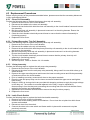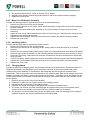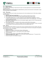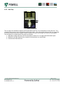
1
Switchgear & Instrumentation PowlVac100TM Circuit Breaker Service Manual Issue Date: August 2012 Document Revision 0.1 STD/CUS/036 This page intentionally left blank REVISION HISTORY Revision 0.0 0.1 Date Description 11/07/12 Original created from technical information taken from the PV100 User Guide 08/08/12 Updated following comments from internal review Prepared Charlotte Pestell Charlotte Pestell The Design and Development Department is responsible for the data contained in this standard document. The relevant departmental managers and team leaders are responsible for ensuring the correct use of this data within their departments. The Engineering Manager is responsible for the correct use of the data within the Contract Engineering department. AUTHORISED BY SD&D Manager_______________________ DATE____30th August 2012 P Dale PV100 VCB Service Manual Rev 0.1 Page 3 of 26 This page intentionally left blank PV100 VCB Service Manual Rev 0.1 Page 4 of 26 Contents 1 Getting Started ........................................................................................................... 7 1.1 1.2 1.3 2 Introduction ................................................................................................................. 9 2.1 3 Electrical Schematic .................................................................................................... 10 Circuit Breaker Settings .............................................................................................11 3.1 3.2 3.3 3.4 4 About this Service Manual ............................................................................................. 7 How to Use this Service Manual .................................................................................... 7 Application Notes .......................................................................................................... 8 Primary Trip Prop ........................................................................................................ 11 Latch Check Switch ..................................................................................................... 12 Close Latch Shaft ........................................................................................................ 13 Cam and Fundamental Link Positions ......................................................................... 14 3.4.1 Breaker Open, Spring Charged ........................................................................ 14 3.4.2 Breaker Open, Spring Discharged ................................................................... 14 3.4.3 Breaker Closed, Spring Discharged ................................................................. 15 3.4.4 Breaker Closed, Spring Charged ..................................................................... 15 3.4.5 Interlocks ......................................................................................................... 16 Replacing Parts .........................................................................................................19 4.1 4.2 4.3 4.4 4.5 Overview ..................................................................................................................... 19 Removal of the Main Closing Spring ........................................................................... 19 4.2.1 Slow Close Operation ...................................................................................... 19 Replacement Procedures ............................................................................................ 20 4.3.1 Close Coil Assembly ........................................................................................ 20 4.3.2 Primary/Secondary Trip Coil Assembly ............................................................ 20 4.3.3 Y Relay Assembly ............................................................................................ 20 4.3.4 Latch Check Switch ......................................................................................... 20 4.3.5 Motor Cut-Off Switch Assembly ....................................................................... 21 4.3.6 Auxilliary Switch ............................................................................................... 21 4.3.7 Charging Motor ................................................................................................ 21 Adjustments ................................................................................................................ 22 4.4.1 Trip Lever ........................................................................................................ 22 4.4.2 Stroke .............................................................................................................. 22 4.4.3 Nut Gap ........................................................................................................... 23 Replacement Parts ...................................................................................................... 24 List of Figures Figure 1 PowlVac100TM Vacuum Circuit Breaker Figure 2 Electrical Schematic Figure 3 Primary Trip Prop Figure 4 Latch Check Switch Figure 5 Close Latch Shaft Figure 6 Breaker Open, Spring Charged, Links Reset Figure 7 Breaker Open, Spring Discharged Figure 8 Breaker Closed, Spring Discharged Figure 9 Breaker Closed, Spring Charged Figure 10 Nut Gap PV100 VCB Service Manual Rev 0.1 9 10 11 12 13 14 14 15 15 23 Page 5 of 26 List of Tables Table 1 Replacement Parts .................................................................................................................... 25 PV100 VCB Service Manual Rev 0.1 Page 6 of 26 1 Getting Started IMPORTANT NOTICE – READ THIS FIRST This Installation and Maintenance Guide does not purport to cover every detail of the installation and operation of the PowlVAC100TM (PV100) circuit breaker. Requests for further guidance or information on this or any other product should be directed to Powell UK. Our switchgear is manufactured in accordance with IEC standards. Powell UK cannot provide any assurances that this product will comply with the wide variety of local codes, regulations or ordinances that apply in different areas of the world. 1.1 About this Service Manual This guide provides user service instructions for the PV100 Vacuum Circuit Breaker (VCB). The purpose of this manual is to familiarize the user and maintenance personnel with the basic capabilities of the VCB. Only proven safe installation techniques are covered. This manual was not prepared for inexperienced maintenance personnel. It is not intended to constitute a training program or to provide sufficient background for personnel, not experienced with this type of electrical system, to install the system described in this service manual. The end user is responsible for ensuring that no persons should be authorised to install or carry out maintenance work on the system without having read this manual. All rights reserved. Reproduction of any part of this service manual in any form whatsoever without the written permission of Powell UK is forbidden. Additional copies can be obtained from the After Sales Services Dept. of Powell UK, Bradford, United Kingdom. The information contained within this service manual is confidential and cannot be transferred to a third party without the written consent of Powell UK. All efforts have been made to ensure the accuracy of the contents of this service manual. However should any errors be detected, Powell UK would greatly appreciate being informed of them. The above notwithstanding Powell UK can assume no responsibility for any errors in this manual or the consequences thereof. The policy of Powell UK is one of progressive improvement in design, construction and operation. Systems and equipment referred to in this user guide are subject to changes in keeping with this policy. The manufacturer, therefore, reserves the right to make any changes without prior notice. 1.2 How to Use this Service Manual This service manual is arranged and subdivided to provide useful information with a minimum of searching. The key to easy reference is the Table of Contents. Every subject, in the Table of Contents, is listed with a reference number and the page on which the item can be found. Each subject is numbered by Chapter, Paragraph and Sub-paragraph, for example: 4.1.2. “4" - Chapter number. “1" - Main paragraph topic. PV100 VCB Service Manual Rev 0.1 Page 7 of 26 “2" - Breakdown of Main paragraph topic. The page number, along with the number of pages in this user guide, is located in the outside corner of each page. For convenience, all illustrations and tables are numbered in sequential order. Familiarity with the Table of Contents will facilitate locating particular information easily. Personnel responsible for the system should review all of the Table of Contents for future reference and an overall understanding of the guide. Then read the service manual and study the illustrations thoroughly. 1.3 Application Notes Warranty Powell UK warrant the switchgear against defects in material or workmanship under normal use for a period of 18 months from the date of shipment from our premises or 12 months from the date the equipment is put into service, whichever occurs first. In the event of a failure arising during the warranty, Powell UK will undertake to repair or replace the switchgear at our option, provided always that it is found to be defective. The warranty obligations of Powell UK will not extend to defects caused by wrong or negligent operation, accident, overloading, unsuitable operating conditions, or by failure of the End User to comply with any instruction given by Powell UK with regard to its operation or installation. Powell UK is not liable under any circumstances for special, economic, financial, indirect or consequential damages (including loss of profit, loss of use, loss of production, loss of contracts) or for expenses sustained as a result of switchgear malfunction or incorrect application. Safety at Work. The voltages present in certain parts of the switchgear are capable of inflicting a severe electric shock and may be lethal. It is the responsibility of the owner and / or the End User to ensure that the installation of the switchgear and the way in which it is operated and maintained complies with the requirements of the Health and Safety at Work Act in the United Kingdom, and with other applicable legislation and regulations and codes of practice in the UK or elsewhere. The manufacturer accepts no liability for any consequences resulting from inappropriate or incorrect installation of the equipment. Training If additional training is required then contact Powell UK or their designated agent. Type of operating environment The intended operating environment is limited to being housed within an electrical switchroom or substation that is suitable for protecting the equipment. Access to the switchroom and switchgear must be prevented except by trained and authorised personnel. General Operating Requirements Users must have electrical experience and be able to interpret control circuit diagrams, electrical schematics and general arrangement drawings. Minimum age (years). Eighteen (18), or minimum permissible age required by End User’s national law. PV100 VCB Service Manual Rev 0.1 Page 8 of 26 2 Introduction Figure 1 PowlVac100TM Vacuum Circuit Breaker The Powell UK PowlVac100TM (PV100) Vacuum Circuit Breaker (VCB) is an automatically operated electrical switch used to protect a Medium Voltage (MV) electrical circuit from overload or short circuit via the use of Vacuum Interrupters (VI). These VCBs are designed to be incorporated within the Powell UK Type 298 range of Medium Voltage IEC Switchgear and Motor Control Centres. Please refer to the Powell UK MV298 User Guide for Circuit Breaker Cubicles incorporating PV100 Circuit Breaker (Document Reference STD/CUS/030) for further details. This document details the how to service the circuit breaker and replace components if necessary. Please use this document in conjunction with the PV100 User Guide (STD/CUS/035). PV100 VCB Service Manual Rev 0.1 Page 9 of 26 2.1 Electrical Schematic Figure 2 Electrical Schematic PV100 VCB Service Manual Rev 0.1 Page 10 of 26 3 Circuit Breaker Settings This section details the procedures for setting the circuit breaker up in the factory. These settings should not need to be performed again. 3.1 Primary Trip Prop The procedure for setting the primary trip prop is as follows: Secondary Trip Prop Roller 0.005-0.015" Primary Trip Prop Primary Trip Prop Adjusting Screw Trip Bar Primary Trip Prop Roller Figure 3 Primary Trip Prop Remove the main closing spring (refer to Section 4.2 for details). Adjust the primary trip prop adjusting screw so that with the fundamental linkage in the reset position, the clearance between the primary trip prop roller and the secondary trip prop is 0.005” to 0.015”. The primary trip prop adjusting screw is accessible from the rear of the stored energy mechanism and is located inside the hole beside the lower middle insulator. Replace the main closing spring. PV100 VCB Service Manual Rev 0.1 Page 11 of 26 3.2 Latch Check Switch The procedure for setting the latch check switch is as follows: Latch Check Operator Secondary Trip Prop Adjusting Screw Nut 0.045" Latch Check Switch Pivot Screw Secondary Trip Prop Adjusting Screw Figure 4 Latch Check Switch Remove the main closing spring (refer to Section 4.2 for details). Rotate the crank arms until the spring charge indicator displays “Closing Spring Charged”. Loosen the two screws which secure the latch check switch and rotate the latch check switch about the pivot screw downward to the lowest position allowed. The latch switch contacts are now open. Insert a 0.045” gauge between the secondary trip prop adjusting screw and latch check operator. Rotate the latch check switch upwards until the contacts are closed. An audible click of the contacts will be heard. At the position where the click is heard, hold the switch and retighten the two screws which secure the latch check switch. Remove the gauge To confirm that the latch check switch is properly set, slowly depress and release the manual trip operator to verify that the latch check switch opens and closes properly. The latch check switch contacts will open as the latch check operator is moved by the manual trip operator away from the secondary trip prop adjusting screw. Slowly withdraw the manual trip operator and the latch check switch contacts should close when the latch check operator is between 0.045” to 0.015” away from the secondary trip prop adjusting screw. Depress the manual close operator and rotate the crank arm until resistance is felt. Depress and hold the manual trip operator inward and rotate the crank arms until the spring charge indicator displays “Closing Spring Discharged”. Replace the main closing spring. PV100 VCB Service Manual Rev 0.1 Page 12 of 26 3.3 Close Latch Shaft Close Latch Shaft Motor CutOff Cam Charging Motor Drive Shaft Figure 5 Close Latch Shaft The procedure for setting the close latch shaft is as follows: Remove the indicator plate. Loosen the locking nut from the close bar adjusting screw whilst the holding the position of the close bar adjusting screw with a screw driver. Back out the close bar adjusting screw by turning the screw counter-clockwise 2 full turns. Manually charge the circuit breaker main closing spring with a manual charging handle until the spring charge indicator displays “Closing Spring Charged”. Turn the close bar adjusting screw clockwise until the main closing spring discharges, then trip the breaker. Turn the close bar adjusting screw 3 to 3.5 full turns counter-clockwise. Retighten the locking nut holding the screw. Turn the close bar adjusting screw clockwise until the main closing spring discharges, then trip the breaker. Close and trip the breaker to ensure proper operation Replace the indicator plate. PV100 VCB Service Manual Rev 0.1 Page 13 of 26 3.4 Cam and Fundamental Link Positions This section shows the positions of the cam and fundamental link dependant on breaker and spring status. 3.4.1 Breaker Open, Spring Charged Figure 6 Breaker Open, Spring Charged, Links Reset 3.4.2 Breaker Open, Spring Discharged Figure 7 Breaker Open, Spring Discharged PV100 VCB Service Manual Rev 0.1 Page 14 of 26 3.4.3 Breaker Closed, Spring Discharged Figure 8 Breaker Closed, Spring Discharged 3.4.4 Breaker Closed, Spring Charged Figure 9 Breaker Closed, Spring Charged PV100 VCB Service Manual Rev 0.1 Page 15 of 26 3.4.5 Interlocks 3.4.5.1 50kA/3150A and 63kA/3150A Circuit Breakers/Earth Switches The procedure for setting the interlocks on the circuit breakers that are fitted within a 1000mm wide cubicle is as follows: Adjust the top lever setting screw to 12mm Push the interlock lever forward so that the interlock key is clear of the racking cam on the racking arm and parallel with the lower key. Ensure that both keys are set parallel and clear of the cam Ensure the circuit breaker/earth switch is completely removed from the cubicle. Raise the circuit breaker/earth switch using a suitable lifting device in order to gain access to the underside. Adjust the M5 setting screw on the keeper bracket positioned at the lower end of the interlock lever until the screw touches the interlock lever maintaining the interlock key clear of the cam and parallel to the second key. M5 Setting Screw on a keeper bracket PV100 VCB Service Manual Rev 0.1 Page 16 of 26 Adjust the front end of the threaded rod on the plunger lever, located underneath the circuit breaker/earth switch until the plunger rod-end on the side of the breaker is 25mm from the housing. Adjust here 25mm The interlocks are now set. 3.4.5.2 40kA/1600A and 50kA/2000A Circuit Breakers/Earth Switches The procedure for setting the interlocks on the circuit breakers/earth switches that are fitted within a 700mm wide cubicle is as follows: Ensure the circuit breaker/earth switch is completely removed from the cubicle. Raise the device from the service trolley using a suitable lifting device in order to gain access to the underside. Set the thread length between the inside faces to 48mm. 48mm Lower the circuit breaker/earth switch back onto a suitable service trolley taking care to protect the interlock plunger. Close the circuit breaker/earth switch whilst on the service trolley. Adjust the left hand interlock screw until the interlock finger cleats the interlock cam and tighten fastener. PV100 VCB Service Manual Rev 0.1 Page 17 of 26 Left Hand Interlock Screw (Pressing lower interlock finger) Interlock cam Right Hand Interlock Screw (Pressing upper interlock finger) Racking Fingers Open the circuit breaker/earth switch and ensure that the lower interlock finger now positively engages with the interlock cam and blocks the racking. Place the device into the “test” position. With the circuit breaker cubicle door open, check that the upper interlock finger blocks the racking. With the fascia still removed, close the door to the circuit breaker cubicle and use the viewing glass to check that the upper interlock finger has cleared the interlock cam. NOTE: Alternatively, this test can also be carried out by fitting a door interlock override bracket when the circuit breaker cubicle door is open. Fit door interlock bracket here (if required) If closed, open the circuit breaker cubicle door and re-fit the device fascia. Carry out appropriate mechanical checks as per QSF959/QSF996. PV100 VCB Service Manual Rev 0.1 Page 18 of 26 4 Replacing Parts 4.1 Overview In the case of failure of parts or detailed fault finding work it may be necessary to temporarily remove the main closing spring in order to perform a slow close operation. It may also be necessary to replace the following components: Close Coil Assembly Primary Trip Coil Assembly Y Relay Assembly Latch Check Switch The following sections detail the procedure for the removal/replacement of these parts and also how to perform a slow close operation Replacement work may only be performed by trained personnel familiar with the characteristics of the individual circuit breaker, in accordance with all relevant safety regulations and with other overriding instructions. It is recommended that Powell UK service personnel carry out any servicing and repair work. Please contact the Site Services team for further information regarding maintenance personnel and activities. 4.2 Removal of the Main Closing Spring The closing spring must be removed in order to perform slow closing of the circuit breaker. The procedure for spring removal is as follows: 1. With the main closing spring discharged and the circuit breaker contacts open, remove the bolt at the top of the spring rod together with the flat washer, and lock washer. 2. Remove the horizontal bracket at the top of the main closing spring, by unfastening the two attachment bolts. 3. Remove the spacer from below the bracket. 4. Turn the bracket 90˚, and replace it on the top of the spring yoke. 5. Place the spacer above the bracket with the flat washer above the spacer. 6. Insert bolt and tighten until the tension is taken off the connecting rods. 7. With a slight rocking motion of the main closing spring assembly, the connecting rods can now be unhooked from the spring yoke pins and the main closing spring assembly can be removed. To re-install the main closing spring assembly, reverse the preceding removal procedure. Please note that care should be taken on reassembly to ensure correct location of the flat washer, lock washer and spacer. 4.2.1 Slow Close Operation The slow closing of mechanism described is not required for routine maintenance; however, it may be a useful procedure for troubleshooting circuit breaker mis-operation. 1. With the main closing spring assembly removed, rotate the camshaft so that the crank arms are pointing downward. The fundamental linkage will now move into the reset position. 2. Push the manual close operator inward and hold it in while operating the charging handle to rotate the camshaft. 3. When the close release latch arm has passed the close shaft latch plate, the manual close operator may be released. As the main closing cam engages the main cam roller, the jackshaft will commence to rotate. 4. Continue to operate the charging handle until the crank arms point upward. The circuit breaker will now be closed and there will be a gap between the operating pushrod lock nuts and the pivot blocks. 5. Return the circuit breaker to the open position by depressing the manual trip operator. PV100 VCB Service Manual Rev 0.1 Page 19 of 26 4.3 Replacement Procedures Before carrying out any of the procedures detailed belwo, please ensure that the secondary disconnect is fully removed and that all 4.3.1 Close Coil Assembly Perform the following steps to replace the primary shunt trip coil assembly: 1. Remove the front cover of the circuit breaker. 2. Disconnect the cables to the close coil assembly 3. Remove the two bolts which hold the close coil assembly to the circuit breaker frame and remove the assembly. 4. Bolt the new close coil assembly in place and reconnect it to the wiring harness. Ensure the connections are secure. 5. Close the circuit breaker electrically several times to ensure that the close coil assembly is functioning properly. 6. Replace the front cover. 4.3.2 Primary/Secondary Trip Coil Assembly Perform the following steps to replace the primary shunt trip coil assembly: 1. Remove the front cover of the circuit breaker. 2. Disconnect the cables to the trip coil assembly 3. Remove the two bolts which hold the primary shunt trip coil assembly to the circuit breaker frame and remove the assembly. 4. Bolt the new primary shunt trip coil assembly in place and reconnect it to the wiring harness. Ensure the connections are secure. 5. Trip the circuit breaker electrically several times to ensure that the primary shunt trip coil assembly is functioning properly. 6. Replace the front cover. 7. Set the trip lever. Refer to Section 4.4.1 for details. 4.3.3 Y Relay Assembly Perform the following steps to replace the anti-pump relay assembly: 1. Remove the front cover of the circuit breaker. 2. Disconnect the wires from the anti-pump relay assembly, being careful to note which wires go to which terminal. 3. Remove the upper mounting screw and loosen the lower mounting screw and lift relay assembly off and remove from the circuit breaker. 4. Prior to installing new relay, reconnect all wires to the proper terminals. 5. Place the new anti-pump relay over the lower screw and reinstall the upper screw and tighten both screws. 6. Relays in 250V dc closing circuits are provided with dropping resistors to apply the proper voltage to the relay coil. The resistor is mounted adjacent to the relay. It may be replaced by disconnecting it from the relay and unscrewing the mounting feet from the circuit breaker frame, replacing the resistor and reassembling. 7. Operate the circuit breaker several times to ensure the relay functions properly. 8. Replace the front cover. 4.3.4 Latch Check Switch Perform the following steps to replace the latch check switch assembly: 1. Remove front cover of the circuit breaker. 2. Remove two screws holding switch to mechanism. Do not lose the nut plate into which these screws are threaded. 3. Disconnect wires from the switch. 4. Connect the wires to the new switch and fasten switch in place with screws and nut plate previously removed. PV100 VCB Service Manual Rev 0.1 Page 20 of 26 5. Set the latch check switch. Refer to Section 3.2 for details. 6. Operate circuit breaker electrically several times to ensure the switch functions properly. 7. Replace the front cover. 4.3.5 Motor Cut-Off Switch Assembly Perform the following steps to replace the motor cut-off switch assembly: 1. Remove the front cover of the circuit breaker. 2. Disconnect the wires from the motor cut-off switch assembly, being careful to note which wires go to which terminal. 3. Remove the two bolts holding the assembly to the circuit breaker floor pan and remove the assembly. 4. Install the new cut-off switch assembly by bolting it to the floor pan. Reconnect the wiring and no adjustments are needed at this time. 5. Operate the circuit breaker electrically several times to ensure the switch functions properly. 6. Replace the front cover. 4.3.6 Auxilliary Switch Perform the following steps to replace the auxiliary switch: 1. Remove the front cover of the circuit breaker. 2. Disconnect the wires from the auxiliary switch, being careful to note which wires go to which terminal. 3. Remove the two screws holding the auxiliary switch to its mounting bracket and remove the switch. 4. Insert the new switch and attach it to the mounting bracket with the two screws removed in Step 4 5. Reconnect the wiring. Make sure the wires are connected to the same terminals from which they were removed. 6. Verify the auxiliary spare contacts are wired in accordance with the original circuit breaker diagram. 7. Operate the circuit breaker electrically several times to ensure the switch functions properly. 8. Replace the front cover 4.3.7 Charging Motor In order to replace the charging motor, the procedure below should be followed. Please note that on a 700mm wide breaker, the charging motor is attached to the side of the circuit breaker and on the 1000mm wide circuit breakers, it is attached to the baseplate and the fixings are accessed from underneath. Due to the smaller size of the wheels on the 1000mm wide 50kA circuit breaker, this circuit breaker will need to be lifted in order to gain access to the fixings. The larger size of the wheels on the 1000mm wide 63kA circuit breaker means that the fixings are accessible with the circuit breaker on the service trolley. 1. Remove the front cover of the circuit breaker. 2. Release the cable ties securing the wires to the charging motor. 3. Disconnect the connections to the charging motor. 4. Unscrew the fixings securing the charging motor to the circuit breaker frame. 5. The motor can now be removed either through the access holes in the circuit breaker frame (700mm wide circuit breaker) or through the front (1000mm wide circuit breaker). 6. The process is reversed when fitting a new charging motor. Note the charging motor is always supplied complete with coupler and fitted to its mounting plate PV100 VCB Service Manual Rev 0.1 Page 21 of 26 4.4 Adjustments Once replaced, the following components will require accurate adjustments to ensure that the breaker operates correctly. Before carrying out any of the adjustments detailed below, please ensure that the circuit breaker is open and the springs are fully discharged. 4.4.1 Trip Lever In order to set the trip lever for either the primary trip coil or the secondary trip coil, follow the procedure described below: 1. Manually close the circuit breaker 2. Place a 0.090” feeler gauge between the trip coil armature and the trip coil itself 3. Slowly depress the trip coil armature until it makes contact with the feeler gauge. 4. The breaker should not trip. If it does, bend the trip lever downwards using pliers in order to increase the gap between the trip coil armature and the trip lever and repeat steps 1 to 4 until the circuit breaker does not trip. 5. When step 3 is performed without the circuit breaker tripping, replace the 0.90” feeler gauge with the 0.30” feeler gauge. 6. Slowly depress the trip coil armature until it makes contact with the feeler gauge. 7. The breaker should trip. If it doesn’t, bend the trip lever upwards using pliers in order to decrease the gap between trip coil armature and the trip lever and repeat steps 1 to 7. 4.4.2 Stroke The stroke determines the distance of travel of the vacuum interrupter and is set in the factory when the circuit breaker is new. This will only need to be conducted again if the vacuum interrupters are replaced. The procedure for this is as follows: 1. Close the breaker. 2. Measure the nut gap on each phase using a suitable gauge. 3. Measure the closed stroke on each phase using suitable gauges. 4. Trip the breaker. 5. Measure the open stroke on each phase using suitable gauges. 6. Deduct the closed stroke measurement from the open stroke measurement. The result of this should be between 7mm – 9mm. 7. Re-test using the Circuit Breaker Analyser. PV100 VCB Service Manual Rev 0.1 Page 22 of 26 4.4.3 Nut Gap Nut Gap Figure 10 Nut Gap The nut gap is the distance between the contact block and the nut on the bottom of the push rod. This cannot be set as such, but is affected by setting the stroke. Once the stroke has been set, it is important to measure and record the nut gap in order to monitor the wear occurring to the vacuum interrupters. The procedure for measuring the nut gap is as follows: 1. Manually charge and close the circuit breaker as there is no nut gap with the breaker open. 2. Measure the gap between the nut and the contact block on each phase. 3. Record the measurements. PV100 VCB Service Manual Rev 0.1 Page 23 of 26 4.5 Replacement Parts Description Catalogue Number Charging Motor 48V dc 40kA 1600A 50kA 2000A 50kA 3150A 63kA 3150A 09095G00000900 09095G00000901 Charging Motor 110V dc 40kA 1600A 50kA 2000A 50kA 3150A 63kA 3150A 09095G00000286 09095G00000191 Charging Motor 125V dc 40kA 1600A 50kA 2000A 50kA 3150A 63kA 3150A Charging Motor 240V dc 40kA 1600A 50kA 2000A 50kA 3150A 63kA 3150A 09095G00000286 09095G00000191 09095G00000902 09095G00000903 Charging Motor 120V ac 40kA 1600A 50kA 2000A 50kA 3150A 63kA 3150A 09095G00000286 09095G00000191 Charging Motor 240V ac 40kA 1600A 50kA 2000A 50kA 3150A 63kA 3150A 09095G00000902 09095G00000903 Close Coil 48V dc (All models) 09095G00000909 Close Coil 110V dc (All models) 09095G00000910 Close Coil 125V dc (All models) 09095G00000672 Close Coil 240V dc (All models) 09095G00000911 Close Coil 120V ac (All models) 09095G00000912 Close Coil 240V ac (All models) 09095G00000913 Primary Trip Coil 48V dc (All models) 09095G00000904 Primary Trip Coil 110V dc (All models) 09095G00000905 Primary Trip Coil 125V dc (All models) 09095G00000020 Primary Trip Coil 240V dc (All models) 09095G00000906 Primary Trip Coil 120V ac (All models) 09095G00000907 Primary Trip Coil 240V ac (All models) 09095G00000908 Secondary Trip Coil 48V dc (All models) 09095G00001017 Secondary Trip Coil 110V dc (All models) 09095G00001020 Secondary Trip Coil 125V dc (All models) 09095G00001007 Secondary Trip Coil 240V dc (All models) 09095G00001018 Secondary Trip Coil 120V ac (All models) 09095G00001017 Primary Trip Coil 240V ac (All models) 09095G00001019 PV100 VCB Service Manual Rev 0.1 Page 24 of 26 Auxiliary Switch (All models) 102109LN Ground Connection (All models) 69433G01 Latch Check Switch (All models) BA-2RV2-A2 Motor Cut-off Switch Assembly (All models) 50756G03P Table 1 Replacement Parts PV100 VCB Service Manual Rev 0.1 Page 25 of 26 PV100 VCB Service Manual Rev 0.1 Page 26 of 26