1
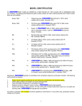
Installation & Service Manual
Radar Speed Sensor
for Radars Other Than Raven
Manual Rev. E, SPEED SENSOR, 5-97
Order: 50, 5-28-97, #016-0159-414
016-0159-414
5/97
TABLE OF CONTENTS
RADAR SPEED SENSOR SYSTEM COMPONENTS ........................................................................................... 2
INSTALLATION FOR VEHICLES WITH FACTORY EQUIPPED RADAR ............................................................ 4
1. JOHN DEERE WITH DICKEY JOHN RADAR ......................................... 4
2. JOHN DEERE WITH MAGNAVOX RADAR ............................................ 6
3. CAT CHALLENGER WITH DICKEY JOHN RADAR .................................... 8
4. CASE-IH WITH DICKEY JOHN RADAR ............................................ 9
5. FORD WITH DICKEY JOHN RADAR .............................................. 10
6. WHITE/AGCO-ALLISON '94/'95/'96 WITH DICKEY JOHN RADAR ................... 11
7. FORD GENESIS/VERSATILE/NEW HOLLAND ...................................... 12
8. JOHN DEERE 7000/8000/9000 SERIES ......................................... 13
9. CAT CHALLENGER MOD-C/D ROW CROP 35,45,55 WITH D-J RADAR ................. 14
10. CASE WITH TRW RADAR ..................................................... 15
INSTALLATION FOR VEHICLES WITH NON-FACTORY EQUIPPED RADAR ................................................ 16
1.
2.
3.
4.
DICKEY JOHN RADAR INSTALLATION ...........................................
MAGNAVOX RADAR INSTALLATION ..............................................
TRW RADAR INSTALLATION ...................................................
MECHANICAL RADAR INSTALLATION ............................................
16
17
18
19
CALCULATION OF SPEED ................................................................................................................................... 22
1. SPEED CAL PROCEDURE FOR ALL CONSOLES (EXCEPT SCS 440) ................... 22
2. SPEED CAL PROCEDURE FOR SCS 400 .......................................... 23
APPENDIXES
1. MAGNAVOX RADAR MOUNTING BRACKET ................................................................................................. 24
2. TRW DRILLING TEMPLATE-MOUNTING HOLES FOR LEFT SIDE OF VEHICLE...................................... 25
3. TRW DRILLING TEMPLATE-MOUNTING HOLES FOR RIGHT SIDE OF VEHICLE ................................... 26
1
RADAR SPEED SENSOR SYSTEM COMPONENTS
Locate the radar to be used from the radar type column in Table 1. Proceed to the vehicle
type column and find the vehicle that corresponds with the radar type chosen. Identify
the column that specifies the Console program letter. All Console program letters can
be found on a serial tag located on the back of the Console (See Figure 1). Choose the
radar speed sensor part numbers that matches with the vehicle type and program letter
of the Console you are using.
FIGURE 1
Console Revision can be determined by the
letter stamped in REV box on label.
Console Program can be determined by the
letter stamped in PGM box on label.
063-XXXX-XXX
R
RA
AD
DA
AR
R
TY
TYP
PE
E
DICKEY
JOHN
MAGNAVOX
V
VE
EHICL
HICLE
E TY
TYPE
PE
R
RA
AD
DA
AR
R SY
SYS
STE
TEM
MP
P/N’
/N’ss
FO
FOR
RC
CO
ONS
NSO
OLLE
ES
S::
S
SCS
CS 33
3300
S
SCS
CS 55
5500
S
SCS
CS75
7500
S
SCS
CS 44
4400 P
PG
GM
ME
EA
AND
ND U
UP
P
S
SCS
CS 45
4500 P
PG
GM
MA
AA
AN
ND
D UP
UP
S
SCS
CS 46
4600 P
PG
GM
MA
AA
AN
ND
D UP
UP
S
SCS
CS 60
6000 P
PG
GM
MA
AA
AN
ND
D UP
UP
S
SCS
CS 66
6600 P
PG
GM
MA
AA
AN
ND
D UP
UP
S
SCS
CS 70
7000 P
PG
GM
MD
DA
AN
ND
D UP
UP
S
SCS
CS 71
7100 P
PG
GM
MA
AA
AN
ND
D UP
UP
P
P
A
A
G
G
E
E
R
RA
AD
DA
AR
R SY
SYS
STE
TEM
M
P
P/N’
/N’ss FO
FOR
R
CO
CON
NS
SO
OLLES
ES::
S
SCS
CS 40
4000
S
SCS
CS 50
5000
S
SCS
CS 44
4400 P
PG
GM
MA
A TO
TO D
D
S
SCS
CS 70
7000 P
PG
GM
MA
A TO
TO C
C
P
P
A
A
G
G
E
E
CASE IH
115-0159-517
9
063-0159-793
9
AGCO-ALLISON 94/95/96
FORD ***
WHITE *
115-0159-529
10,11
063-0159-822
10,11
JOHN DEERE **
115-0159-519
4
063-0159-795
4
CHALLENGER *
115-0159-518
8
063-0159-794
8
CAT C-MOD, D-MOD
ROW CROP 35,45,55
CHALLENGER
115-0159-627
14
JOHN DEERE 7000/8000/9000
SERIES
115-0159-700
13
FORD
GENESIS/VE RSATILE
NEW HOLLAND 1996
115-0159-709
12
OTHER
115-0159-526
5,16
063-0159-598
5,16
JOHN DEERE **
115-0159-519
6
063-0159-795
6
JOHN DEERE
7000/8000/9000 SERIES
115-0159-700
13
OTHER
115-0159-462
7,17
063-0159-599
7,17
CASE
115-0159-432
15
063-0159-589
15,18
OTHER
115-0159-463
18
063-0159-589
15,18
TRW
*
**
***
TABLE 1
1990 model year or later with factory installed performance monitor
1990 model year or later with factory installed performance monitor
Not used for 7000/8000/9000 series tractors
1990 model year or later with factory installed performance monitor
Not used for Genesis/Versatile tractors
2
Table 2 details the components which are included in the radar speed sensor part numbers
identified in Table 1.
PAGE
RADAR SPEED
SENSOR SYSTEM
PART NUMBERS
COMPONENTS INCLUDED IN CABLE ASSEMBLIES
RADAR CA BLE P/N
RADAR ADAPTER
RADAR INTERFACE
15,18
063-0159-589
115-0159-432
NOT USED
063-0159-590
5,16
063-0159-598
115-0159-434
NOT USED
063-0159-590
7,17
063-0159-599
115-0159-436
NOT USED
063-0159-590
9
063-0159-793
115-0159-517
NOT USED
063-0159-590
8
063-0159-794
115-0159-518
NOT USED
063-0159-590
4,6
063-0159-795
115-0159-519
NOT USED
063-0159-590
10,11
063-0159-822
115-0159-529
NOT USED
063-0159-590
15
115-0159-432
115-0159-432
NOT USED
NOT USED
9
115-0159-517
115-0159-517
NOT USED
NOT USED
8
115-0159-518
115-0159-518
NOT USED
NOT USED
4,6
115-0159-519
115-0159-519
NOT USED
NOT USED
5,16
115-0159-526
115-0159-526
NOT USED
NOT USED
10,11
115-0159-529
115-0159-529
NOT USED
NOT USED
7,17
117-0159-462
115-0159-436
115-0159-522
NOT USED
18
117-0159-463
115-0159-432
115-0159-522
NOT USED
13
115-0159-700
115-0159-700
NOT USED
NOT USED
12
115-0159-709
115-0159-709
NOT USED
NOT USED
14
115-0159-627
115-0159-627
NOT USED
NOT USED
TABLE 2
3
INSTALLATION FOR VEHICLES WITH FACTORY EQUIPPED RADAR
1. JOHN DEERE WITH DICKEY JOHN RADAR
A. 1990 OR LATER MODEL
Figure 2 illustrates how components of the sprayer control system are interconnected.
ORDER SYSTEM PART NO. 063-0159-795
FIGURE 2
Figure 3 illustrates how components of the sprayer control system are interconnected.
ORDER SYSTEM PART NO. 115-0159-519
Compatible with the following Consoles:
SCS 330
SCS 550
SCS 660
SCS 750
SCS 440 - Program E or Later
SCS 450 - Program A or Later
SCS 460 - Program A or Later
SCS 600 - Program A or Later
SCS 710 - Program A or Later
SCS 700 - Program D or Later
FIGURE 3
4
B.
1989 OR EARLIER MODEL
Figure 4 illustrates how components of the sprayer control system are interconnected.
ORDER SYSTEM PART NO. 063-0159-598
FIGURE 4
Figure 5 illustrates how components of the sprayer control system are interconnected.
ORDER SYSTEM PART NO. 115-0159-526
Compatible with the following Consoles:
SCS 330
SCS 550
SCS 660
SCS 750
SCS 440 - Program E or Later
SCS 450 - Program A or Later
SCS 460 - Program A or Later
SCS 600 - Program A or Later
SCS 710 - Program A or Later
SCS 700 - Program D or Later
FIGURE 5
5
2.
JOHN DEERE WITH MAGNAVOX RADAR
A. 1990 OR LATER MODEL
Figure 6 illustrates how components of the sprayer control system are interconnected.
ORDER SYSTEM PART NO. 063-0159-795
FIGURE 6
Figure 7 illustrates how components of the sprayer control system are interconnected.
ORDER SYSTEM PART NO. 115-0159-519
Compatible with the following Consoles:
SCS 330
SCS 550
SCS 660
SCS 750
SCS 440 - Program E or Later
SCS 450 - Program A or Later
SCS 460 - Program A or Later
SCS 600 - Program A or Later
SCS 710 - Program A or Later
SCS 700 - Program D or Later
FIGURE 7
6
B.
1989 OR EARLIER MODEL
Figure 8 illustrates how components of the sprayer control system are interconnected.
ORDER SYSTEM PART NO. 063-0159-599
FIGURE 8
Figure 9 illustrates how components of the sprayer control system are interconnected.
ORDER SYSTEM PART NO. 115-0159-462
Compatible with the following Consoles:
SCS 330
SCS 550
SCS 660
SCS 750
SCS 440 - Program E or Later
SCS 450 - Program A or Later
SCS 460 - Program A or Later
SCS 600 - Program A or Later
SCS 710 - Program A or Later
SCS 700 - Program D or Later
FIGURE 9
7
3.
CAT CHALLENGER WITH DICKEY JOHN RADAR
(1990 OR LATER)
Figure 10 illustrates how components of the sprayer control system are interconnected.
ORDER SYSTEM PART NO. 063-0159-794
FIGURE 10
Figure 11 illustrates how components of the sprayer control system are interconnected.
ORDER SYSTEM PART NO. 115-0159-518
Compatible with the following Consoles:
SCS 330
SCS 550
SCS 660
SCS 750
SCS 440 - Program E or Later
SCS 450 - Program A or Later
SCS 460 - Program A or Later
SCS 600 - Program A or Later
SCS 710 - Program A or Later
SCS 700 - Program D or Later
FIGURE 11
8
4.
CASE-IH WITH DICKEY JOHN RADAR (1990 OR LATER)
Figure 12 illustrates how components of the sprayer control system are interconnected.
ORDER SYSTEM PART NO. 063-0159-793
FIGURE 12
Figure 13 illustrates how components of the sprayer control system are interconnected.
ORDER SYSTEM PART NO. 115-0159-517
Compatible with the following Consoles:
SCS 330
SCS 550
SCS 660
SCS 750
SCS 440 - Program E or Later
SCS 450 - Program A or Later
SCS 460 - Program A or Later
SCS 600 - Program A or Later
SCS 710 - Program A or Later
SCS 700 - Program D or Later
FIGURE 13
9
5.
FORD WITH DICKEY JOHN RADAR (1990 OR LATER)
Figure 14 illustrates how components of the sprayer control system are interconnected.
ORDER SYSTEM PART NO. 063-0159-822
FIGURE 14
Figure 15 illustrates how components of the sprayer control system are interconnected.
ORDER SYSTEM PART NO. 115-0159-529
Compatible with the following Consoles:
SCS 330
SCS 550
SCS 660
SCS 750
SCS 440 - Program E or Later
SCS 450 - Program A or Later
SCS 460 - Program A or Later
SCS 600 - Program A or Later
SCS 710 - Program A or Later
SCS 700 - Program D or Later
FIGURE 15
10
6.
WHITE/AGCO-ALLISON '94/'95/'96 WITH DICKEY JOHN
RADAR (1990 OR LATER)
Figure 16 illustrates how components of the sprayer control system are interconnected.
ORDER SYSTEM PART NO. 063-0159-822
FIGURE 16
Figure 17 illustrates how components of the sprayer control system are interconnected.
ORDER SYSTEM PART NO. 115-0159-529
Compatible with the following Consoles:
SCS 330
SCS 550
SCS 660
SCS 750
SCS 440 - Program E or Later
SCS 450 - Program A or Later
SCS 460 - Program A or Later
SCS 600 - Program A or Later
SCS 710 - Program A or Later
SCS 700 - Program D or Later
FIGURE 17
11
7.
FORD GENESIS / VERSATILE / NEW HOLLAND
Illustration below shows how components of the sprayer control system are interconnected.
ORDER SYSTEM PART NO. 115-0159-709
Compatible with the following Consoles:
SCS 330
SCS 550
SCS 750
SCS 450 - Program A or Later
SCS 460 - Program A or Later
SCS 600 - Program A or Later
SCS 710 - Program A or Later
SCS 700 - Program D or Later
SCS 440 - Program E or Later
90 SERIES VERSATILE
96-97 NEW HOLLAND
80 SERIES GENESIS
96-97 NEW HOLLAND
FIGURE 18
1.
2.
3.
4.
5.
FIGURE 19
Locate radar on tractor.
80 series Genesis / New Holland:
Remove battery cover to access radar.
90 series Versatile / New Holland: Radar is mounted below tractor radiator.
Locate connection between radar cable and tractor wiring harness.
Install Radar Interface Cable between radar cable and tractor wiring harness.
Connect Radar Interface Cable to Raven Console in cab of tractor.
Program Console as described on following page.
12
8.
JOHN DEERE 7000/8000/9000 SERIES
Illustration below shows how components of the sprayer control system are interconnected.
Compatible with the following Consoles:
ORDER SYSTEM PART NO. 115-0159-700
SCS
SCS
SCS
SCS
SCS
SCS
FIGURE 20
1992 OR EARLIER 7000 SERIES TRACTOR
450
460
600
710
700
440
-
Program
Program
Program
Program
Program
Program
A
A
A
A
D
E
SCS 330
SCS 550
SCS 750
or Later
or Later
or Later
or Later
or Later
or Later
FIGURE 21
1993 OR LATER 7000 SERIES, 8000
SERIES, & 9000 SERIES TRACTOR
1992 OR EARLIER 7000 SERIES
1.
2.
3.
Remove right-hand console trim ring (seven screws).
Remove pencil tray (two screws).
Locate 2-pin connector under right-hand console. See Figure 20.
NOTE: If cable is not accessible, remove left-hand console panel near
floor. Locate connector and push towards window. Pull connector
out right-hand side and connect to interface cable.
4.
5.
6.
Connect interface cable to 2-pin connector.
Position connector. Install pencil tray and console trim ring.
Connect Interface Cable to Raven Console and planter monitor adapter cable
(If used).
1993 OR LATER 7000 SERIES, 8000 SERIES, & 9000 SERIES
1.
2.
3.
4.
Locate fuse panel on right hand console. Open up fuse panel and locate
2-pin metri-pack connector inside fuse panel. See Figure 20.
NOTE: If connector is not in fuse panel, Locate connector under foam strip
behind right-hand console wrap around. Harness may be under the
right-hand console. See Figure 21.
Connect interface cable to 2-pin plug connector.
Position connector near floor and replace foam strip.
Connect Interface Cable to Raven Console and planter monitor adapter cable
(If used).
IMPORTANT: IF MORE DETAIL IS REQUIRED, REVIEW JOHN
DEERE PLANTER RADAR SIGNAL ADAPTER KIT
(BA26054) INSTALLATION INSTRUCTIONS.
13
9.
CAT CHALLENGER MODEL C / D (1990 0R LATER)
ROW CROP 35, 45, 55 (1996 OR LATER)
WITH DICKEY JOHN RADAR
Figure 22 illustrates how components of the sprayer control system are interconnected.
ORDER SYSTEM PART NO. 115-0159-627
Compatible with the following Consoles:
SCS 330
SCS 550
SCS 660
SCS 750
SCS 440 - Program E or Later
SCS 450 - Program A or Later
SCS 460 - Program A or Later
SCS 600 - Program A or Later
SCS 710 - Program A or Later
SCS 700 - Program D or Later
FIGURE 22
14
10. CASE WITH TRW RADAR
Figure 23 illustrates how components of the sprayer control system are interconnected.
ORDER SYSTEM PART NO. 063-0159-589
FIGURE 23
Figure 24 illustrates how components of the sprayer control system are interconnected.
ORDER SYSTEM PART NO. 115-0159-432
Compatible with the following Consoles:
SCS 330
SCS 550
SCS 660
SCS 750
SCS 440 - Program E or Later
SCS 450 - Program A or Later
SCS 460 - Program A or Later
SCS 600 - Program A or Later
SCS 710 - Program A or Later
SCS 700 - Program D or Later
FIGURE 24
15
INSTALLATION FOR VEHICLES WITH NON-FACTORY EQUIPPED
RADAR
1. DICKEY JOHN RADAR INSTALLATION
Figure 25 illustrates how components of the sprayer control system are interconnected.
ORDER SYSTEM PART NO. 063-0159-598
FIGURE 25
Figure 26 illustrates how components of the sprayer control system are interconnected.
ORDER SYSTEM PART NO. 115-0159-526
Compatible with the following Consoles:
SCS 330
SCS 550
SCS 660
SCS 750
SCS 440 - Program E or Later
SCS 450 - Program A or Later
SCS 460 - Program A or Later
SCS 600 - Program A or Later
SCS 710 - Program A or Later
SCS 700 - Program D or Later
FIGURE 26
16
2.
MAGNAVOX RADAR INSTALLATION
Figure 27 illustrates how components of the sprayer control system are interconnected.
ORDER SYSTEM PART NO. 063-0159-599
FIGURE 27
Figure 28 illustrates how components of the sprayer control system are interconnected.
ORDER SYSTEM PART NO. 117-0159-462
Compatible with the following Consoles:
SCS 330
SCS 550
SCS 660
SCS 750
SCS 440 - Program E or Later
SCS 450 - Program A or Later
SCS 460 - Program A or Later
SCS 600 - Program A or Later
SCS 710 - Program A or Later
SCS 700 - Program D or Later
FIGURE 28
17
3.
TRW RADAR INSTALLATION
Figure 29 illustrates how components of the sprayer control system are interconnected.
ORDER SYSTEM PART NO. 063-0159-589
FIGURE 29
Figure 30 illustrates how components of the sprayer control system are interconnected.
ORDER SYSTEM PART NO. 117-0159-463
Compatible with the following Consoles:
SCS 330
SCS 550
SCS 660
SCS 750
SCS 440 - Program E or Later
SCS 450 - Program A or Later
SCS 460 - Program A or Later
SCS 600 - Program A or Later
SCS 710 - Program A or Later
SCS 700 - Program D or Later
FIGURE 30
18
4.
MECHANICAL RADAR INSTALLATION
A. DICKEY JOHN
Mount radar to manufacturer's recommendations. If the manufacturer's installation for
mounting the radar is not available, the following guidelines will assure proper
installation:
NOTE: It is suggested that a large, heavy mounting bracket be attached to the
vehicle from for use when mounting the radar.
1)
Park vehicle on level ground.
2)
Align top edge of bracket with tractor frame if horizontal.
3)
Use carpenter's level to verify that mounting bracket is level.
4)
The center of radar lens must be 30" to 36" from the ground.
5)
The line of sight from the lens to the ground must not be obstructed by structure
or tires.
6)
Bolt radar to mounting bracket.
19
B.
MAGNAVOX
Mount radar to manufacturer's recommendations. If the manufacturer's installation for
mounting the radar is not available, the following guidelines will assure proper
installation:
NOTE: It is suggested that a large, heavy mounting bracket be attached to the
vehicle from for use when mounting the radar. See Appendix 1 for a sketch
of suggested mounting bracket
1)
Park vehicle on level ground.
2)
Align top edge of bracket with tractor frame if horizontal.
3)
Use carpenter's level to verify that mounting bracket is level.
4)
The center of radar lens must be 30" to 36" from the ground.
5)
The line of sight from the lens to the ground must not be obstructed by structure
or tires.
6)
Bolt radar to mounting bracket.
20
C.
TRW
Mount radar to manufacturer's recommendations. If the manufacturer's installation for
mounting the radar is not available, the following guidelines will assure proper
installation:
NOTE: It is suggested that a large, heavy mounting bracket be attached to the
vehicle from for use when mounting the radar.
1)
Park vehicle on level ground.
2)
Align top edge of bracket with tractor frame if horizontal.
3)
Use carpenter's level to verify that mounting bracket is level.
4)
Fasten plumb line to mounting plate (See Detail A).
5)
Tape template (See Appendix B or C) to mounting plate and check that actual plumb
line and "plumb sight line" (on template) are aligned.
6)
Drill four 7/16" diameter holes in the center of the circles drawn on the templates.
7)
The center of the radar lens must be 24" to 36" from the ground (See Detail B).
8)
The line of sight from the lens to the ground must not be obstructed by structure
or tires.
9)
Bolt radar to mounting bracket.
21
CALCULATION OF SPEED
1. SPEED CAL FOR ALL CONSOLES (EXCEPT SCS 400)
The switches and keys referred to below are on the Raven SCS Consoles. Use Steps
1 and 2 if Console has SP1/SP2 select.
NOTE: Numbers in brackets [ ] are metric equivalents.
1)
2)
3)
Reset Console according to the instruction manual.
Complete "INITIAL CONSOLE PROGRAMMING" in the Installation and Service Manual for
your Console. Select SP2 for correct operation of Radar. If your Console does
not have SP1/SP2 select, you must either update your Console's program, or use
a radar adapter (P/N 063-0159-590).
For all Consoles (except SCS 500*) enter the SPEED CAL for your Radar in key
labelled
.
Speed cal value can be determined by the following:
RADAR TYPE
SPEED CAL
Dickey John
820 [207]
Magnavox
612 [155]
TRW
612 [155]
*For SCS 500 Console, enter a SPEED CAL number that is half of the recommended
value shown above.
4)
Set POWER switches to ON, all other switches to OFF.
5)
Enter "0" in key labelled
6)
Drive 1 mile [1 kilometer]. To achieve the most accurate calibration, accelerate
and decelerate slowly.
CAUTION:
7)
.
Do not use vehicle odometer to determine distance.
lines or highway markers.
Read DISTANCE by depressing key labelled
Use section
.
DISTANCE display should read a value of approximately 5280 [1000]. If it reads
between 5260-5300 [990-1010], the SPEED CAL is 612 [155]. If the DISTANCE display
reads any other value, divide SPEED CAL by the value observed in DISTANCE, then
multiply by 5280 [1000]. This will give you the correct value to enter for SPEED
CAL. Round off to the nearest 3 digit number.
EXAMPLE:
Assume DISTANCE reads 5000 [980].
ENGLISH UNITS:
METRIC UNITS:
= 612 x 5280 = 646.3
= [155] x [1000] = [158.5]
5000
[980]
The number to enter for SPEED CAL is 646 [159].
8)
Recheck the new SPEED CAL calculated in Step 7 as follows:
Enter the new SPEED CAL number as in Step 3.
a)
b)
Repeat Steps 5, 6, and 7.
c)
Final Speed cal may vary with Radar mount.
22
2.
SPEED CAL PROCEDURE FOR SCS 400 CONSOLE
NOTE: Numbers in brackets [ ] are metric equivalents.
1)
Set the MAN/AUTO switch MAN, POWER switch to ON, MASTER switch to OFF, and BOOM
switches to OFF.
2)
Enter "990" as boom length in key labelled
3)
Enter "0" in keys labelled:
4)
Enter the Speed cal value for your Radar in key labelled
.
.
Speed cal value can be determined by the following:
RADAR TYPE
SPEED CAL
Dickey John
820 [207]
Magnavox
612 [155]
TRW
612 [155]
5)
Drive 1 mile [1 kilometer]. To achieve the most accurate calibration, accelerate
and decelerate slowly.
CAUTION:
6)
Do not use vehicle odometer to determine distance.
lines or highway markers.
Read TOTAL AREA by depressing key labelled
Use section
.
TOTAL AREA display should read a value of approximately 10.0. If it reads 9.9,
10.0, 10.1, the SPEED CAL for your vehicle is correct. If the TOTAL AREA display
reads any other value, divide SPEED CAL by the value observed in TOTAL AREA, then
multiply by 10. This will give you the correct value to enter for SPEED CAL. Round
off to the nearest 3 digit number.
EXAMPLE:
Assume SPEED CAL is 612 and TOTAL AREA reads 9.3.
ENGLISH UNITS:
=
612 = 65.8 x 10 = 658
9.3
The number to enter for SPEED CAL is 658.
8)
Recheck the new SPEED CAL calculated in Step 7 as follows:
Zero out TOTAL AREA display as in Step 3.
a)
b)
Enter new Speed cal number as in Step 4.
c)
Repeat Steps 5, 6, and 7.
d)
Final Speed cal may vary with Radar mount.
NOTE: Enter actual Boom lengths, Meter cal, set GPA and Time as described in
the OPERATION/PROGRAMMING section of the SCS 400 INSTALLATION AND
SERVICE MANUAL, prior to spraying.
23
APPENDIX 1
MAGNAVOX RADAR MOUNTING BRACKET
24
APPENDIX 2
TRW DRILLING TEMPLATE (37 DEGREE ANGLE)
MOUNTING HOLES FOR LEFT SIDE OF VEHICLE
25
APPENDIX 3
TRW DRILLING TEMPLATE (37 DEGREE ANGLE)
MOUNTING HOLES FOR RIGHT SIDE OF VEHICLE
26
Radar Speed Sensor
for Radars Other Than Raven
Installation & Service Manual
(P/N 016-0159-414 Rev E 2/09)
Raven Industries
Applied Technology Division
P.O. Box 5107
Sioux Falls, SD 57117-5107
Toll Free (U.S. and Canada): (800)-243-5435
or Outside the U.S. :1 605-575-0722
Fax: 605-331-0426
www.ravenprecision.com
[email protected]
Notice: This document and the information provided are the property of Raven Industries, Inc. and may only be used as authorized
by Raven Industries, Inc. All rights reserved under copyright laws.