1
Installation & Service Manual
SCS Sidekick Injection System
Disclaimer
While every effort has been made to ensure the accuracy of this document,
Raven Industries assumes no responsibility for omissions and errors. Nor is any
liability assumed for damages resulting from the use of information contained
herein.
Raven Industries shall not be held responsible or liable for the effects of
atmospheric conditions and sunspot activity on the performance of our products.
Raven Industries cannot guarantee the accuracy, integrity, continuity, or
availability of the GPS signal from the U.S. Department of Defense/NAVSTAR
GPS satellites, the OmniSTAR correction service or the WAAS correction
service.
Raven Industries accepts no responsibility for the use of the signal for other than
the stated purpose. Raven Industries shall not be responsible or liable for
incidental or consequential damages or a loss of anticipated benefits or profits,
work stoppage or loss or impairment of data arising out of the use, or inability to
use, the SmarTrax or any of its components.
Important Safety Information
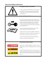
Recognize Safety Information
This is the safety-alert symbol. When you see this symbol on
your machine or in this manual, be alert to the potential for
personal injury. Follow recommended precautions and safe
operating practices.
Follow Safety Instructions
Carefully read all safety messages in this manual and on the
machine’s safety labels. Keep safety labels in good condition.
Replace missing or damaged safety labels. Verify that new
equipment components and replacement parts include the
current safety labels. Replacement safety labels are available
from your Raven dealer.
Learn how to operate the machine and controls. Do not let
anyone operate the machine without instruction.
Keep the machine in proper working condition. Unauthorized
modifications to the machine may impair the machine function
and/or safety, and may shorten the life of the machine.
If you do not understand any part of this manual and need
assistance, contact your local Raven dealer.
Understand Signal Words
Signal words – DANGER, WARNING, or CAUTION – are used
with the safety-alert symbol. DANGER signifies the most serious
hazards.
DANGER or WARNING safety labels are located near specific
hazards. General precautions are listed on the CAUTION safety
labels. CAUTION also calls attention to safety messages in this
manual.
i
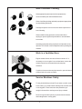
Wear Protective Clothing
Wear appropriate personal protective equipment as
recommended by the chemical Manufacturer.
Wear close-fitting clothing and safety equipment appropriate
for the job being performed.
Prolonged exposure to loud noise can cause impairment or
loss of hearing.
Wear suitable hearing protection such as earmuffs or
earplugs to protect against objectionable or uncomfortable
loud noises.
Operating equipment safety requires the full attention of the
operator. Do not wear music headphones while operating the
machine.
Work in a Ventilated Area
Engine exhaust fumes can cause illness or death. If it is
necessary to run an engine in an enclosed area, remove the
exhaust fumes from the area with an exhaust pipe
extension.
If you do not have an exhaust pipe extension, open the doors
to allow fresh air into the work area.
Service Machines Safely
Tie long hear behind your head. Do not wear a necktie, scarf,
loose clothing, or necklace when working near machine tools
or moving parts. These items have the potential to get
caught in the machine, causing severe injury or death.
Remove rings and other jewelry to prevent electrical shorts
and entanglement in moving parts.
ii
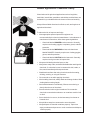
Handle Agricultural Chemicals Safely
Chemicals used in agricultural applications such as fungicides,
herbicides, insecticides, pesticides, rodenticides, and fertilizers can
be harmful to your health and the environment if not used carefully.
Always follow all label directions for effective, safe, and legal use of
agricultural chemicals.
To reduce the risk of exposure and injury:
• Wear appropriate personal protective equipment as
recommended by the chemical manufacturer. In the absence of
manufacturer’s instructions, follow these general guidelines:
o
Chemicals labeled DANGER are the most toxic. Generally
requires use of safety goggles, a respirator, gloves, and skin
protection.
o
Chemicals labeled WARNING are less toxic than those
labeled DANGER. Generally requires use of safety goggles,
gloves, and skin protection.
o
Chemicals labeled CAUTION are the least toxic. Generally
requires use of gloves and skin protection.
•
Always avoid inhaling chemical spray or dust.
• Always have soap, water, and towels available when working with
chemicals. If a chemical comes in contact with skin, hands, or
face, wash immediately with soap and water.
•
Wash hands and face after using chemicals and before eating,
drinking, smoking, or using the restroom.
•
Do not smoke or eat while applying chemicals.
•
After handling chemicals, always bathe and change clothes. Wash
clothing before wearing it again.
•
Seek medical attention immediately if illness occurs during or
shortly after the use of chemicals.
•
Store chemicals in their original containers. Do not transfer
chemicals to unmarked containers or to containers used for food
or drink.
•
Store chemicals in a secure, locked area away from human or
livestock food.
•
Keep children away from areas used to store chemicals.
•
Always dispose of chemical containers properly. Triple-rinse
empty containers and puncture or crush containers and dispose
of them properly.
iii
Service and Operate Chemical Sprayers
Safely
Chemicals used in agricultural sprayers can be harmful to your
health and the environment if not used carefully.
Always follow all label directions for effective, safe, and legal use
of agricultural chemicals.
To reduce risk of exposure and injury:
•
Wear appropriate personal protective equipment as
recommended by the chemical manufacturer. Refer to the
Handle Agricultural Chemicals Safely Section for further
information.
•
Fill, flush, calibrate, and decontaminate the sprayer in an
area where runoff will not reach ponds, lakes/streams,
livestock areas, gardens, or people.
•
Keep children away from chemicals, chemical solutions, and
rinsing agents.
•
If spray or chemical concentrate comes in contact with skin,
hands, or face, wash immediately with soap and water. If
spray or chemical concentrate gets into the eyes, flush
immediately with water.
•
If the nozzle clogs or the system malfunctions, stop the
engine and relieve spray pressure from the system.
•
Do not use your mouth to clear obstructions from nozzle tips
or other components. Keep spare nozzle tips on hand for
replacement.
•
Minimize risk of spray drift:
o
Use large nozzle tips operated at lower pressures.
o
Do not operate the solution delivery system at pressures
o
exceeding 50 psi (345kPa, 3.5 bar).
Do not spray when winds exceed 10 mph/16 kmph.
o
Do not spray when the wind is blowing toward a nearby
sensitive crop, garden, or populated area.
•
Properly dispose of unused chemicals, flushing solution
and empty chemical containers.
•
Decontaminate equipment used in mixing, transferring, and
applying chemicals after use.
iv
Clean the Vehicle of Hazardous Pesticides
During application of
hazardous pesticides,
residue can build up on the
inside or outside of the
vehicle. Clean the vehicle
thoroughly according to the
Use instructions of
hazardous pesticides.
When exposed to hazardous pesticides, clean the interior and
exterior of the vehicle daily to keep it free of visible dirt and
contamination accumulation.
1. Sweep or vacuum the floor of the cab.
2. Clean headliners and inside cowlings of the cab.
3. Wash the entire exterior of the vehicle.
4. Dispose of any wash water contaminated with hazardous
concentrations of active or non-active ingredients according to
published regulations or directives.
Dispose of Waste Properly
Improper disposal of waste can threaten the environment and ecology.
Potentially harmful waste used with equipment include oil, fuel,
coolant, brake fluid, filters, and batteries.
Use leak-proof containers when draining fluids. Do not use food or
beverage containers, as this may cause someone to accidentally
ingest the chemicals.
Do not pour waste onto the ground, down a drain, or into any water
source.
Air conditioning coolants escaping into the air can cause damage to
the atmosphere. Government regulations may require a certified air
conditioning service center to recover and recycle used air
conditioning coolants.
Inquire on the proper method to recycle or dispose of waste from your
local environmental or recycling center.
Live With Safety
Before returning the machine to the customer, make sure the machine
is functioning properly, especially the safety systems. Install all
guards and shields.
v
THIS PAGE INTENTIONALLY LEFT BLANK
vi
016-0159-819
07/09
TABLE OF CONTENTS
SYSTEM SPECIFICATIONS ...............................................................................................................2
INTRODUCTION ................................................................................................................................. 3
OPERATION .......................................................................................................................................4
SYSTEM DIAGRAM ............................................................................................................................5
INSTALLATION
1.
INJECTION MODULE .............................................................................................................6
2.
PLUMBING .............................................................................................................................. 7
3.
CONSOLE .............................................................................................................................. 9
4.
CABLING ...............................................................................................................................10
BATTERY CONNECTIONS .............................................................................................................. 11
CONSOLE FEATURES .................................................................................................................... 12
CONSOLE PROGRAMMING ............................................................................................................13
1.
CALCULATING “METER CAL” ..............................................................................................14
2.
CALCULATING “VALVE CAL” ............................................................................................... 14
3.
CALCULATING “SPREADER CONSTANT” ......................................................................... 15
4.
DETERMINING COUNTS PER REVOLUTION OF GEAR MOTOR SHAFT ........................ 15
5.
ALTERNATE METHOD OF CALCULATING SPREADER CONSTANT ............................... 16
6.
CONSOLE CALIBRATION .................................................................................................... 17
7.
OTHER DISPLAY FEATURES ............................................................................................. 19
HIDDEN FEATURES ........................................................................................................................ 20
INITIAL INJECTION SET-UP ............................................................................................................. 29
PREVENTIVE MAINTENANCE ......................................................................................................... 30
APPENDIXES
1.
2.
3.
4.
5.
6.
7.
8.
9.
10.
11.
12.
13.
14.
SIDEKICK INJECTION SYSTEM TROUBLESHOOTING FLOWCHART .............................31
PROCEDURE TO TEST CONSOLE ENABLE .................................................................... 32
PROCEDURE TO TEST CABLES ....................................................................................... 33
PROCEDURE TO TEST SPEED SENSOR EXTENSION CABLES ................................... 34
PROCEDURE TO TEST METERING SENSOR CABLES .................................................. 35
PROCEDURE TO TEST TACH GENERATOR ................................................................... 36
PROCEDURE TO TEST METERING SENSOR .................................................................. 37
PROCEDURE TO RE-CALIBRATE PUMP .......................................................................... 38
PROCEDURE TO TEST FLOW MONITOR SENSOR ........................................................ 39
SENSITIVITY ADJUSTMENT PROCEDURE, MANIFOLD FLOW MONITOR SENSOR .....40
PROCEDURE TO TEST VACUUM SWITCH ....................................................................... 41
ALTERNATE TANK SELECTION ......................................................................................... 42
SERIAL INTERFACE ............................................................................................................43
SCS-SIDEKICK COMMUNICATION STRINGS ..................................................................... 44
REPLACEMENT PART SHEETS
1
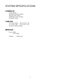
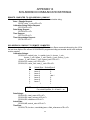
SYSTEM SPECIFICATIONS
CONSOLE:
4 Digit Display
Keyboard Data Entry System
Microprocessor Based
PWM Motor Control W/Tach
Automatic Control
CABLES:
15’ Console Cable
P/N 115-0171-130
27’ Product Cable
P/N 115-0171-138
Extension Cables Available
MODULE:
Pump: Piston
150 PSI Max
Capacity:
5-200 oz/min
2
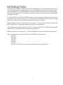
INTRODUCTION
The Raven SCS SIDEKICK INJECTION SYSTEM is designed to improve the accuracy and uniformity of spray applications. Its performance relies on the installation and preventive maintenance of
the complete sprayer. It is important that this Installation and Service Manual be reviewed thoroughly
before operating the system. This Manual provides a simple step-by-step procedure for installing and
operating this system.
The SCS SIDEKICK INJECTION SYSTEM consists of a computer based Control Console, one Injection Module, an In-Line Mixer and cables. The Console mounts directly to a Raven Console for easy
operator use. Boom inputs and speed are shared with the Raven Console.
Injection Module mounts to the framework of the sprayer. The In-Line Mixer mounts just before the
Boom On/Off Valves. Appropriate cabling is furnished for field installation.
The operator sets the target application rate to be injected and the SCS SIDEKICK automatically
maintains the flow regardless of vehicle speed or gear selection.
A Raven Console controls the carrier. The SCS SIDEKICK Console controls the Injection System.
Raven Consoles that may be used with the SCS SIDEKICK are listed below:
SCS 440
SCS 450
SCS 460
SCS 600
SCS 660
SCS 661
SCS 330 & SCS 400 may be used if user fabricates the mounting bracket.
3
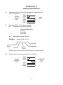
OPERATION
The SCS SIDEKICK Console must receive a “boom sense signal” from the Raven Console to which
it is connected. The harness provided with the SCS SIDEKICK Console shares the On/Off Boom
signal from the Raven Console to which it is connected. For this reason, both consoles BOOM CAL
numbers must match.
The SCS SIDEKICK Console must also share speed with the Raven Console to which it is connected.
Therefore, it is important that the initial speed selection SP1 or SP2 be the same on both consoles.
Also, both Speed Cal numbers must match.
Refer to Initial System Setup.
To operate the Sidekick Injection System, place the Raven Console’s Master and Boom switches to
OFF. Place the Sidekick OFF/HOLD/RUN switch to RUN. The Injection Pump should not run until
the Master switch and at least one Boom switch are turned on. Place Master and Boom switches to
ON. The Injection Pump should now run. To stop injecting chemical and still run the carrier, place the
OFF/HOLD/RUN switch to HOLD. This will flush the carrier of the chemical being injected.
4
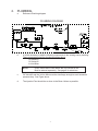
SYSTEM DIAGRAM
5
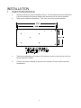
INSTALLATION
1.
INJECTION MODULE
a.
b.
Select an area that is close to the Boom Valves. This will keep the amount of chemical
in the line between the Injection Module and the carrier line as small as possible.
Reference the platform dimensions. This is the size of the Injection Module.
c.
Take into consideration the location of the injection module’s hand valves and drain.
DO NOT BLOCK THESE.
d.
Position the Injection Module for access to the Injection Pump to perform periodic
maintenance.
6
2.
PLUMBING
a.
Reference Plumbing diagram
PLUMBING DIAGRAM
b.
It will be necessary to add the following components to the existing carrier plumbing.
These components shall be plumbed as shown above.
CK Valve #1
CK Valve #2
In-Line Mixer
NOTE:
Check Valves and In-Line Mixers are not included in kits.
Must be ordered separately. See page 8 for selections.
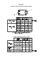
c.
CK Valve #2 and the In-Line Mixer must be sized large enough to avoid excessive
pressure drop. See Figure above.
d.
The Injection Point should be as close to the Boom Valves as possible.
7
FIGURE 1
CHECK VALVE SELECTION CHART
IN-LINE MIXER SELECTION CHART
8
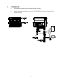
3.
CONSOLE
a.
Disconnect the cable from the existing Raven Console.
b.
Use the brackets provided to mount the SCS SIDEKICK Console to the top of the
Raven Console.
9
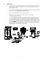
4.
CABLING
a.
Connect both Flow Control and Speed cables from the SCS SIDEKICK Console to the
Raven Console. Connect the existing Flow Control cable and Speed Sensor to the
SCS SIDEKICK cable.
b.
Connect the Red and White Power Wires from the SCS SIDEKICK Console directly to
the vehicle battery. SEE BATTERY CONNECTIONS.
c.
Route the SCS SIDEKICK cables out of the vehicle cab.
d.
Connect the 15 foot Console Control Cable to the 27’ Product Cable.
Use di-electric grease provided.
e.
Turn OFF/HOLD/RUN switch to OFF and route the Red and White battery wires to the
12-volt vehicle battery. Attach the White battery wire to the NEGATIVE(-) battery
terminal and the Red battery wire directly to the POSITIVE (+)battery terminal. (See
below) (DO NOT CONNECT RED AND WHITE WIRES TO THE STARTER). Secure
the battery wires with plastic cable ties. DO NOT tie the battery wires close to the
existing battery leads or any other electrical wiring. Connect the Product cable to the
Injection Module. Use di-electric grease provided.
10
BATTERY CONNECTIONS
11
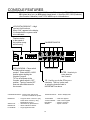
CONSOLE FEATURES
IMPORTANT: This Console requires selection of US (acres), SI (hectares), or TU (1,000 sq. ft.) area;
SP1 (wheel drive, etc.) or SP2 (radar) speed sensor; LI (liquid) or GR1, GR2 (Granular).
(See Console Calibration) Hold TOTAL AREA key to view selections.
LCD DIGITAL READOUT - 4-digit
read-out of all functions.
When “CAL” appears in the display,
it indicates that the system needs
to be calibrated.
Flashes relative
to the speed of
the injection pump
while running
OFF/HOLD/RUN - Place switch
in RUN position to apply
product. Place switch in HOLD
position when shutting the
Injection Pump off.
To Turn off all power to the
Console, place switch in OFF
position. Turning Console OFF
does not affect data stored in
the console.
CALIBRATION KEYS
FUNCTION KEYS
ENTER - Used only to
enter data into
the Console.
CE - Use like you do the CE key on a
calculator. This key is also used
to select the features listed in
IMPORTANT box above.
CALIBRATION KEYS-- Used to enter data into the
Console to calibrate the system.
FUNCTION KEYS -- Used to Display Data
BOOM CAL
TOTAL AREA
TOTAL VOLUME
DISTANCE
SPEED
SPEED CAL
METER CAL
FLOW RATE
-- Length of Boom in inches or [cm].
Select Boom number by using
UP/DOWN arrow keys.
-- Determined by Speed Sensor
-- Meter Calibration Number
-- Target Application Rate
12
-----
Total Area Applied
Total Volume Applied
Distance Traveled
Speed of Vehicle
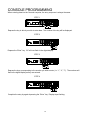
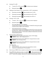
CONSOLE PROGRAMMING
When entering data into the Console computer, the entry sequence is always the same.
STEP 1
Depress the key in which you wish to enter data. The number of the key will be displayed.
STEP 2
Depress the “Enter” key. 3-E will now flash in the digital display.
STEP 3
Depress the keys corresponding to the number you wish to enter (i.e. “1”, “2”, “7”). The numbers will
flash in the digital display as they are entered.
STEP 4
Complete the entry by again depressing the “Enter” key. Display stops flashing.
13
1.
CALCULATING "METER CAL"
The Meter calibration number is stamped on the tag attached to each Injection Pump. Write down
this number for future reference when programming the Console computer.
2.
CALCULATING "VALVE CAL"
1)
The initial Control Valve calibration number is 123. After operating the system, this number may be
refined. See definition below:
VALVE SPEED DIGIT
BRAKE POINT DIGIT
DEAD-BAND DIGIT
To change the Valve Cal setting, depress the key labelled
for 5 seconds. The display will
show the current valve calibration number. Enter a new valve calibration number if desired.
Valve Speed Digit: Controls response time of Control Valve motor.
Brake Point Digit:
CAUTION:
Running the Control Valve too fast will cause
the system to oscillate.
Range:
1 to 9
Sets the percent away from target rate at which the Control Valve motor
begins braking, so as not to overshoot the desired rate.
Range:
Dead-Band Digit:
1-Slow
9-Fast
0 to 9
0 = 5%
1 = 10%
9 = 90%
Allowable difference between target and actual application rate,
where rate correction is not performed.
Range:
1 to 9
14
1 = 1%
9 = 9%
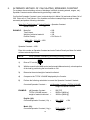
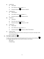
3.
CALCULATING "SPREADER CONSTANT" (If using liquid, skip to step 6)
[only available if programmed in GR1 or GR2]
1)
Find the cubic feet [Cubic cm] of discharge per 1 revolution of the Gear Motor shaft.
L = Length in inces [cm], of belt travel per 1 revolution of Gear Motor shaft
GH = Gate Height in inches [cm]
GW = Gate Width in inches [cm]
Cubic Feet [cubic cm] of Discharge per 1 revolution of Gear Motor shaft: (For GR2, calculation
must include cu ft of both granular metering devices per 1 revolution of the gear motor shaft).
cu ft/rev. of sensor = L x GH x GW
1728
cu cm/rev. of sensor = L x GH x GW
EXAMPLE:
1)
2)
3)
L
GH
GW
= 13 inches [33 cm]
= 7 inches [18 cm]
= 15 inches [38 cm]
cu ft/rev. of sensor = 13" x 7" x 15" = .790
1728
cu cm/rev. of sensor = 33 x 18 x 38 = 22,572
2)
For RATE displayed in 1 lb increments:
Spreader Constant (1 lb) = counts per rev of Gear Motor shaft
cu ft/rev. of Gear Motor shaft
EXAMPLE:
3)
For 80 counts per rev
Spreader Constant = 80 = 101
.790
For RATE displayed in 1 Kg increments
Spreader Constant (1 Kg) = counts per 1 rev of sensor x 100,000
cu cm / rev of Gear Motor shaft
EXAMPLE:
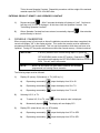
4.
80 counts per rev = 8,000,000 = 797
22,572
DETERMINING COUNTS PER REVOLUTION OF GEAR MOTOR SHAFT
Counts per 1 rev of Gear Motor shaft may be determined by entering a METER CAL number of 10,
enter 0 in TOTAL VOL and turning sensor exactly 1 revolution. The number in TOTAL VOL will be
the counts per 1 rev of Gear Motor shaft.
15
5.
ALTERNATE METHOD OF CALCULATING SPREADER CONSTANT
For systems where calculating volume of discharge is difficult (metering wheels, augers, etc.).
Spreader Constant can be determined by performing a catch test.
Confirm that Spreader Constant is zero (no decimal point in Meter Cal) and enter a Meter Cal of
200. Enter zero in Total Volume. Run machine and collect a sample large enough to weigh
accurately and perform following calculation.
Meter Cal x Total Volume X Product Density = Spreader Constant
Actual Volume
10
EXAMPLE:
Meter Cal
Total Volume
Weight of collected material
Product Density
= 200
= 200
= 128
= 50.0 lbs/cu. ft.
= 200 x 200 = 312 x 50 = 1560
128
10
Spreader Constant = 1560
Enter this number as Spreader Constant and enter Product Density as Meter Cal which
will have a decimal point now.
NOTE:
Verify Spreader Constant by performing following procedure.
1)
Enter a "0" into the
.
2)
With the console in the MAN mode (see Automatic/Manual control), unload a portion
of the load by positioning the boom switch to ON.
3)
Determine the actual weight of material collected.
4)
Compare to the TOTAL VOLUME displayed by the Console.
5)
Perform the following calculation to correct the Spreader Constant if desired:
Corrected Spreader Constant =
EXAMPLE:
old Spreader Constant
TOTAL VOLUME amount
weight of material collected
old Spreader Constant x TOTAL VOLUME
weight of material collected
=
=
=
English (US):
Corrected Spreader Constant (1 lb) =
Metric (SI):
Corrected Spreader Constant (1 kg) =
16
228 [797]
2000 lbs [4400 kg]
1950 lbs [4290 kg]
228 x 2000
1950
= 234
[797] x [4400] = [817]
[4290]
This is the new Spreader Constant. Repeat this procedure until the weight of the metered
material equals the TOTAL VOLUME value.
ENTERING PRODUCT DENSITY AND SPREADER CONSTANT
6.
1)
Depress and hold
. After 5 seconds the display will change to "vcal". Continue to
hold key until "S CON" is displayed. At this time, enter the Spreader Constant. See
"Calculating Spreader Constant"/
2)
After a Spreader Constant has been entered, momentarily depress
product density in lbs/cu ft.
. Now enter the
CONSOLE CALIBRATION
When console power is first turned on after all installation procedures have been completed, the
console will display "US" in the display window. This means the console must be calibrated or
programmed before it can be operated. This is a one-time operation which does not have to be
repeated. Turning OFF the power switch does not affect the console memory. All data is retained.
IMPORTANT:
If an entry selection error is made during steps 1-6, place the
OFF/HOLD/RUN switch to the OFF postion. Depress the
key and hold while placing the OFF/HOLD/RUN switch to HOLD or
RUN. This will "reset" the console.
NOTE:
Boom Cal and Speed Cal must match selection and numbers
programmed into existing Raven consoles.
The following steps must be followed:
1)
2)
3)
Display US (acres), SI [hectares], or TU {1000 sq. ft.}.
a)
Depressing momentarily
steps the display from US to SI.
b)
Depressing momentarily
steps the display from SI to TU.
c)
Depressing momentarily
steps the display from TU to US.
Selecting US, SI, or TU.
a)
To select US, SI, or TU, step
b)
Momentarily depress
until the desired code is displayed.
. The display will now display SP1.
Display SP1 (wheel drives, etc.) or SP2 (radar).
a)
Depressing momentarily
steps the display from SP1 to SP2.
b)
Depressing momentarily
steps the display from SP2 to SP1.
17
4)
5)
6)
7)
Selecting SP1 or SP2.
a)
To select SP1 or SP2, step with
b)
Momentarily depress
until desired code is displayed.
.
Displaying LI (liquid sprayer), GR1* (single bed belt), or GR2** (split bed belt).
a)
Depressing momentarily
steps the display from LI to GR1.
b)
Depressing momentarily
steps the display from GR1 to GR2.
c)
Depressing momentarily
steps the display from GR2 to LI.
Selecting LI, GR1, or GR2.
a)
To select Li, GR1, or GR2, step
until desired code is displayed.
b)
Momentarily depress
*
GR1 (Single Bed) Definition of Operation
As boom width is changed, the SCS SIDEKICK CONSOLE will change the speed
of the drive motor to adjust to the desired rate.
**
GR2 (Split Bed) Definition of Operation
As boom width is changed, the SCS SIDEKICK CONSOLE will not adjust the speed
of the drive motor. Instead, the SCS SIDEKICK will count total volume based on the
width of boom remaining on. For this reason, calibration is based on the sum of both
Granular Metering devices.
.
Definition of Boom Calibration keys.
Depressing this key displays selected boom number in DATA display.
EXAMPLE: Boom 1 will be displayed as b-01.
Depressing this key after selecting BOOM CAL changes the boom number.
EXAMPLE: b-01 will change to b-02.
Depressing this key after selecting BOOM CAL changes the boom number.
EXAMPLE: b-02 will change to b-01.
Enter
a)
b)
c)
Boom Data:
Select boom b-01.
Use the same boom width as entered into existing Raven console.
If a boom is not needed, enter a "0" for the width.
8)
Enter the same SPEED CAL as entered into existing Raven console id key labelled
9)
Enter METER CAL calibration number in key labelled
. When programmed in GR1
or GR2 and if spreader constant is used, enter the product density in lbs/cu.ft. as Meter Cal.
NOTE: This key will not display a decimal until a spreader constant has been entered.
18
.
10)
A VALVE CAL calibration number is automatically intered when console is programmed.
To change the VALVE CAL setting, depress key labelled
for 5 seconds. The display
will show the current VALVE CAL calibration number. Enter a new VALVE CAL calibration
number if desired.
11)
Enter the FLOW RATE target application rate in oz/acre if LI is selected or lbs/acre if GR1
or GR2 is selected in key labelled
NOTE:
.
A decimal point is displayed automatically. Therefore, 20 is entered as
20.0, not 2.0.
YOU HAVE NOW COMPLETED PROGRAMMING THE CONSOLE
The display of "CAL" will now extinquish and the console will begin to display data. If not,
repeat procedure starting at step 7.
7)
OTHER DISPLAY FEATURES
1)
To display TOTAL AREA covered, depress key labelled
To "zero out" this total at any time, enter a "0" in this key.
2)
To display TOTAL VOLUME sprayed, depress key labelled
To "zero out" this total at any time, enter a "0" in this key.
3)
To display speed in MPH [km/h], depress key labelled
4)
To display DISTANCE in feet [m] traveled, depress key labelled
To "zero out" this total at any time, enter a "0" in this key.
5)
To display actual application flow rate in oz/acre [dl/dl/ha], place MASTER switch in ON
position and depress key labelled
.
.
.
. To display target application flow rate, place
MASTER switch to OFF and depress key labelled
6)
.
.
To view any of the set calibration numbers, depress the corresponding calibration keys.
19
HIDDEN FEATURES
The SCS-SIDEKICK Console is equipped with many hidden features. Several Console keys have multiple
features located under them. The amount of time a key is held down determines the feature that will be
displayed. The display will flash the coded name of the feature that is being programmed. These features
and their display codes are outlined below: (A detailed explanation of the feature follows this page.
Console
Key
Depress 5 seconds for:
Depress 7 seconds for:
Depress 9 seconds for:
(Alarm Menu)
"A on" / "AoFF"
Display Smoothing
"d on" / "doFF"
(Flo and VAC Alarm)
"u on" / "uoFF"
Program Rev. Number
"-###"
Program Part Number
"P #"
Total Boom Width
"b tot"
Off Target Alarm
"or" (off Rate)
Dual Sensor Alarm
"dF"
Data Lock
flashing "nEu.1" or "old"
Control Delay
"dLAY"
Valve Cal
"uCAL"
Spreader Constant
"SCon"
Flow Rate vol/min
"FLo"
Automatic Rate +/"dELt"
Automatic/Manual Control
"C on" / "CoFF"
Self Test
"tESt"
DATA MENU
Ref. Data Menu Feature
Display Units
Alternates
"US", "SI", or "tU"
"SP1" or "SP2"
"L1" or "GR1" or "GR2"
20
Low Limit Alarm
"LL"
FEATURES UNDER
1)
SEQUENCE TO ACTIVATE DATA-LOCK
a)
Depress
for 5 seconds, NEW CODE message will appear.
b)
Enter 4 digit code within 15 seconds:
EXAMPLE:
2)
For 1234, depress:
and
.
SEQUENCE TO CHANGE DATA-LOCK
a)
Depress
for 5 seconds, OLD CODE message will appear.
b)
Enter 4 digit code within 15 seconds:
and
.
NEW CODE message will appear. Enter 4 digit code within 15 seconds.
EXAMPLE:
3)
For 4321, depress:
and
.
ENTER MODE SEQUENCE WITH ACTIVATED DATA-LOCK
a)
Depress the key into which you wish to enter data.
b)
Depress
, CODE message will appear. Enter your DATA-LOCK CODE. If code is
correct, "E" will appear. Now enter data normally.
*The DATA-LOCK feature prohibits the entry of data without first entering the DATA-LOCK
CODE. If DATA-LOCK is not desired, omit steps above. The DATA-LOCK CODE may be
cleared by entering a code of "0" or by resetting console.
FEATURES UNDER
4)
ALARM MENU
a)
To display ALARM MENU, depress key labelled
the display.
1)
b)
for 5 seconds. "A on" will show in
Momentarily depressing
toggles the display between "A on" and AoFF".
"A on" means alarm is enabled, "A oFF" means alarm is disabled.
To display setting for display smoothing, press and hold key labelled
for 7 seconds.
The display will show "d on" or "doFF". Selecting "d on" means the window displays
target rate when actual rate is within 10% of target rate. Selecting "doFF" means the
window displays actural rate. Console defaults to "d on".
1)
Momentarily depressing
toggles the display between "d on" and "doFF".
21
C)
FLO AND VAC ALARM
The SCS SIDEKICK Injection system features a Flow Monitor and a Vacuum Monitor to alert
the operator in case the system malfunctions. A FLO message in the display indicates an
under application of chemical. See PROCEDURE TO RE-CALIBRATE PUMP. A VAC
message in the display indicates a high vacuum condition on the inlet to the injection pump.
This may cause under application.
1)
To enable or disable VAC and Flow monitor alarms, press and hold the key labelled
for 9 seconds or until "u on" or "uoFF" is displayed. "u on" = VAC and Flow
alarm is ON. "uoFF" - VAC and Flow alarm is OFF.
2)
Momentarily depressing
toggles the display between "u on" and "uoFF".
FEATURES UNDER
5)
DISPLAYING PROGRAM NUMBER, PROGRAM REV., TOTAL BOOM ON
a)
To display Console Program number, depress key labelled
for 5 seconds.
b)
To display Console Program revision, depress key labelled
for 7 seconds.
c)
To display Total Length of boom detected as "on", depress key labelled
for 9
seconds. Display will alternate between "btot" (boom total) and the number in inches of
detected boom length on.
NOTE: This is a trouble shooting tool used to determine if console is reading booms
currently ON.
FEATURES UNDER
6)
OFF TARGET ALARM
Alarm sounds when the actual rate is off from the target rate by a specified percentage. The Off
Target value is preset to 30%, but may be changed to a different number.
a)
b)
Adjusting Off Target value.
1)
Depress
for 5 seconds. Display will show "or". Enter desired new number for
OFF TARGET ALARM.
2)
Depress
to store selection.
Dual Sensor Alarm
When programmed in LI (Liquid) and controlling a Raven Sidekick Injection Pump, the
console monitors the rate sensor and the flow monitor sensor. If there is an unreasonable
difference between rate sensor and the flow monitor sensor, the console will sound an
alarm and the console will display FLO. This means the injection pump is not metering
accurately. Refer to troubleshooting guide for possible causes. The console is preset at a
value of 60. Do NOT change this value. Changing this value may result in Flo alarm being
on all the time or degrade performance of this feature. To access this feature, press and
hold
for 7 seconds until displays "dF". Press any key to exit.
22
7)
FEATURES UNDER
CONTROL DELAY
Depress key labelled
for 5 seconds. "dLAY" will be displayed.
Control
Delay Digit
X000
The Control Delay number is a 4 digit number. The first digit in the Control Delay number represents
the time (in seconds) between when the booms are turned ON and when the Console actually
begins to control the flow rate. A value of 1 - 9 means a delay of 1 - 9 seconds respectively, a value
of 0 means no delay. The remaining 3 digits are always zero. The Control Delay feature only
operates when the booms are toggled OFF or ON in intervals of 30 seconds or less.
8)
9)
FEATURES UNDER
a)
To display current VALVE CAL setting, depress key labelled
for 5 seconds. Display
will change to "uCAL". Release the key to curent valve cal setting. Console defaults to a
valve cal number of 123.
b)
To display SPREADER CONSTANT or to enter a spreader constant, console must be
programmed in GR1 or GR2.
1)
Depress and hold
. After 5 seconds the display will change to "uCAL".
Continue to hold key until "SCon" is displayed. At this time, enter the Spreader
Constant. See "Calculating Spreader Constant".
2)
After a Spreader Constant has been entered, momentarily depress
enter the product density in lbs/cu ft.
. Now
FEATURES UNDER
FLOW RATE VOL/MIN
This feature allows the operator to view the flow rate in volume per minute.
a)
To display volume per minute, depress and hold key labelled
for 5 seconds until the
display shows "FLo". When displaying volume per minute, the display will alternate between
"FLo" and the volume per min reading.
b)
To exit and return to volume per area display, press key labelled
again.
AUTOMATIC RATE +/This feature sets the increment at which flow is increased or decreased in the Auto mode of
operation. Select RATE +/- for product by depressing
for 7 seconds. The display will show
"dELt". Enter the desired amount for +/-.
EXAMPLE: If flow rate is to be changed by "1.0":
Enter a value of 1.0 for RATE +/-. When in Auto, each time the
or
key is depressed, the target flow rate for that product will increase or
decrease by "1.0".
23
LOW LIMIT FLOW SET POINT AND LOW LIMIT ALARM
a)
To display the Low Limit Flow Set Point, depress key labelled
for 9 seconds.
Display will show "LL" and low limit flow rate will appear in the display. A low limit flow
rate may now be entered.
b)
If the actual volume per minute falls below the set limit, the Control stops closing, an alarm
sounds (if enabled) and the display flashes "-LL-".
c)
The low limit value should be determined with all booms ON. This value is automatically
proportioned to the percentage of booms that are ON.
EXAMPLE:
10)
If the entered low limit is 4, and half the total boom length is shut OFF, the
Console will automatically reduce the low limit flow set point to 2.
FEATURES UNDER
AUTOMATIC/MANUAL CONTROL
The console defaults to Automatic Control.
a)
To place console in Manual Control, depress key labelled
show in the display.
1)
11)
for 5 seconds. "C on" will
Momentarily depressing
toggles the display between "C on" and "CoFF".
"CoFF" means control is in the manual mode.
FEATURES UNDER
SELF TEST FEATURE
NOTE:When using self test for testing the system, place the Injection Modules hand valves
in the recirculation position.
SELF TEST allows speed simulation for testing the system while the vehicle is not moving. Enter
the simulated operating speed by depressing the key labelled
for 2 seconds. Display will
show "tESt". If 6 MPH [9.6 km/h] is desired, enter 6.0 [9.6] (See CONSOLE PROGRAMMING).
The SELF TEST speed will clear itself when motion of vehicle is detected by the Speed Sensor.
A SPEED CAL value of 900 [230] or greater is recommended when operating this mode.
NOTE:To prevent nuisance clearing of self test speed, disconnect speed connector on back
of the Console when Radar Speed Sensors are used.
12)
FEATURES UNDER
The following are brief descriptions of features available under the TOTAL VOLUME key.
DISPLAY
Prn
DESCRIPTION
bEgn
Sends data through serial port to attached optional printer to print
field begin and field end pages. (Not available when GPS or Datalog
are ON)
24
DISPLAY
DESCRIPTION
rate
on
Turns rate change alarm ON or OFF. When rate change alarm is
selected ON; alarm sounds 4 long beeps when the Rate 1 calibration
number is changed via the serial port using a valid change request
data string.
file
1
Used only with Raven Application Management System. See
Application Management System manual for more details.
gps
1
fref
0
Allows user to enter up to a four-digit number to represent a field.
Field reference is included in field begin and field end pages and the
data logger time/date string.
baUd
9600
Used in GPS mode and data logging mode. Selectable between
1200 or 9600 baud.
trig
0
Used in data logging mode. The trigger determines how often actual
rate data string (See Appendix 10 for Data Communication String
Formats) is sent to the serial port. The trigger may be either feet
[meters] or seconds.
Unit
ft
Used in data logging mode. The trigger unit is selectable between
feet [meters] or seconds.
dlog
off
Turns data logger ON or OFF. (Not available when GPS is active)
naC
Used only with Raven Application Management System. See
Application Management System manual for more details.
time
Sets time.
Onth
Sets month.
day
Sets day.
year
Sets year.
pdn
Sets power down days wait.
A)
Definition of Data Menu Options:
Depressing this key for 5 seconds displays selected Data Menu features.
Depressing these keys after selecting DATA MENU increments through desired
features.
EXAMPLE: "Prn" "bEgn", "rAtE" "on", "FILE" "1", etc....
25
B)
CONSOLE DATA PRINTOUT
a)
Display will alternate between prn and begn (Print Field Begin).
1)
b)
To Print Field Begin, depress key labelled
.
Display will now alternate between prn and end (Print Field End).
1)
To Print Field End, depress key labelled
.
2)
While end is displayed, if Field Begin is required, depress key labelled
to toggle display to begn.
c)
C)
D)
E)
G)
to advance to RATE CHANGE ALARM ON/OFF.
RATE CHANGE ALARM ON/OFF
a)
Display will alternate between rate and on (Rate Change Alarm On).
b)
Depressing
momentarily changes the display between on and off. A
value of on means alarm is enabled; a value of off means alarm is disabled.
c)
Momentarily depress
to advance to GPS FILE REFERENCE.
GPS FILE REFERENCE
a)
Display will alternate between file and 1 (GPS File Reference 1).
b)
Enter the GPS file number.
c)
Momentarily depress
to advance to GPS OPTIONS.
GPS OPTIONS
a)
GPS is inactive when the display alternates between gps and inac. The GPS
features are explained further in the GRID APPLICATION SYSTEM MANUAL.
b)
F)
Momentarily depress
Momentarily depress
to advance to FIELD REFERENCE.
FIELD REFERENCE
a)
Display will alternate between fref and 0 (Field Reference 0).
b)
Enter the field number.
c)
Momentarily depress
to advance to BAUD RATE.
BAUD RATE
a)
Display will alternate between baUd and 9600 (Baud Rate 9600).
b)
Depressing
momentarily changes the display between 9600 and 1200.
c)
Momentarily depress
to advance to DATA LOGGER TRIGGER VALUE.
NOTE:The TRIGGER VALUE default is "zero". This value must be changed to a desired
number ranging from 1-9999. The DATA LOGGER features will not work if this
number is not changed.
26
H)
I)
J)
DATA LOGGER TRIGGER VALUE
a)
Display will alternate between trig and 0 (Data Log Trigger Value 0).
b)
Enter the TRIGGER VALUE.
c)
Momentarily depress
to advance to DATA LOGGER TRIGGER UNITS.
DATA LOGGER TRIGGER UNITS
a)
Display will alternate between Unit and ft (Data Log Trigger Units Feet).
b)
Depressing
momentarily changes the display between ft [metr] and
seC. A value that has been chosen as the unit of measurement for the TRIGGER
VALUE programmed previously. (SEC menas seconds has been chosen as the unit
of measure.)
c)
Momentarily depress
to advance to DATA LOGGER.
DATA LOGGER ON/OFF
a)
The DATA LOGGER uses the communications strings listed in Appendix 10 to pass
data out through the serial port. The data is sent at a set time interval or a set
distance traveled, as determined by the values entered in the DATA LOGGER
TRIGGER VALUE and DATA LOGGER TRIGGER UNITS. Upon each trigger, the
Actual Rate string, Data Strings 1, 2, and 3, and the Time/Date string are sent, in
that order. When a Console Calibration value is changed, the Console will automatically send out the Cal 1, 2, and 3 strings. When a Console switch is changed,
the Data 1, 2, 3, Time/Date, and Cal 1, 2, 3 strings will be sent by the Console. The
Data (with Time/Date string included) and Cal strings can also be requested by the
data logger using the request strings shown in Appendix 10.
NOTE:Some options within the DATA MENU LISTINGS may be unavailable if certain
features are ON or active. The options affected are:
CONSOLE DATA PRINTOUT:
Console Data Printout will not be available when
DATA LOGGER is ON or when GPS functions are
active.
GPS OPTIONS:
GPS options will not be available when DATA LOGGER is ON.
DATA LOGGER:
DATA LOGGER will not be available when GPS functions are
active.
b)
Display will alternate between dlog and off (Data Log Off).
c)
Depressing
momentarily changes the display between off and on.
A value of off means DATA LOGGER is disabled; a value of on means
DATA LOGGER is enabled.
d)
Momentarily depress
to advance to TIME.
27
K)
L)
M)
N)
O)
13)
ENTER TIME
a)
Select TIME.
b)
Enter TIME when display flashes time.
c)
Momentarily depress
to advance to MONTH.
ENTER MONTH
a)
Select MONTH.
b)
Enter MONTH when display flashes Onth.
c)
Momentarily depress
to advance to DAY.
ENTER DAY
a)
Select DAY.
b)
Enter DAY when display flashes day.
c)
Momentarily depress
to advance to YEAR.
ENTER YEAR
a)
Select YEAR.
b)
Enter YEAR when display flashes year.
c)
Momentarily depress
to advance to PRINT FIELD BEGIN.
POWER DOWN
Sets number of days of inactivity before console goes into low power consumption mode
and time settings are lost.
FEATURES UNDER KEY
To display information relating to the initial programming of the console, press and hold key
for 5 seconds. The display will scroll through the settings for the following:
US, SI or TU
SP1 or SP2
L1, GR1 or GR2
28
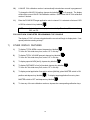
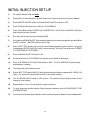
INITIAL INJECTION SET-UP
1)
Fill Injection Module Tank with water.
2)
Place the 3-way valve handle on Injection Pump to the "injection" position on Injection Module.
3)
Place MASTER ON/OFF switch to ON and BOOM ON/OFF switches to OFF.
4)
Place OFF/HOLD/RUN switch to HOLD on SCS SIDEKICK.
5)
Verify correct Boom Widths, SPEED CALS, METER CALS, VALVE CALS, and RATE CALS have
been entered into each Console.
6)
Run main carrier pump at normal operating RPM.
7)
Verify that each BOOM ON/OFF Valve operates and that no nozzles are plugged by operating Boom
ON/OFF switches. (MASTER switch must be ON).
8)
Enter a SELF TEST speed equal to that of normal operating speed in both Consoles, verify entry
by depressing SPEED (6 MPH [9.6 km/h] is recommended). (See Self Test mode under "SPEED"
in "OTHER DISPLAY FEATURES").
9)
Place all BOOM ON/OFF switches to ON.
10)
Set injection Rate on SCS SIDEKICK for desired oz/acre [dl/ha] of application.
11)
Place SCS SIDEKICK OFF/HOLD/RUN switch to RUN. The SCS SIDEKICK Console display
should display a reading.
12)
The system will seek the desired rate.
13)
Enter a SELF TEST speed 2 MPH [3.2 km/h] greater than that initially programmed (8.0 MPH) [12.9
km/h]. The system will automatically correct for this speed variation.
14)
Turn one BOOM ON/OFF switch to OFF position. The system will automatically correct for this
change in boom lengths.
15)
Repeat Steps 11 thru 16 for all remaining injection products.
16)
To verify at any time that the Injection Pump is properly calibrated, refer to PROCEDURE TO RECALIBRATE PUMP.
17)
If your have verified the pumps calibration, drain water from Injection Module Tank and add product.
29
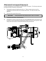
PREVENTIVE MAINTENANCE
Preventive maintenance is most important to assure long life of the system. The following maintenance
procedures should be followed on a regular basis:
1)
Flush Injection system with clean water after use. Failure to clean system can result in
crystallization of products which may foul pump check valves. This may also cause under
application.
2)
Flush and drain system before storing.
IMPORTANT:
Freezing temperature may damage system if water is not drained.
3)
Periodically clean strainer on Injection Module.
4)
Flush Injection system by using flush system (See "RECOMMENDED INJECTION PUMP FLUSH
SYSTEM") or by recirculating water through Injection Module until pump is clear of product. When
storing at the end of season, recirculate RV antifreeze during the last flush.
30
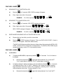
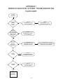
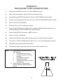
APPENDIX 1
SIDEKICK INJECTION SYSTEM TROUBLESHOOTING
FLOWCHART
SYSTEM
PROBLEM
INJECTION
PUMP
WILL NOT
RUN
YES
GO TO
PROCEDURE TO TEST
CONSOLE ENABLE
GO TO
PROCEDURE TO TEST
CABLES/DRIVE MOTOR
NO
UNABLE
TO CONTROL
INJECTION PUMP
SPEED. PUMP
RUNS FULL
SPEED.
YES
GO TO
PROCEDURE TO TEST
TACH GENERATOR
NO
APPLYING
WRONG
AMOUNT OF
PRODUCT
YES
GO TO
PROCEDURE TO TEST
METERING SENSOR
YES
GO TO
PROCEDURE TO TEST
FLOW MONITOR SENSOR
YES
GO TO
PROCEDURE TO TEST
VACUUM SWITCH
NO
FLOW
ALARM
NO
VACUUM
ALARM
NO
REVIEW
PROBLEM
31
GO TO PROCEDURE TO VERIFY
INJECTION PUMP CAL CALIBRATION
VERIFICATION PROCEDURE
APPENDIX 2
PROCEDURE TO TEST CONSOLE ENABLE
1)
INJECTION PUMP WILL NOT RUN
A)
Verify OFF/HOLD/RUN switch is in the RUN position.
B)
The SCS SIEKICK Console must share the Boom On/Off signal with the console it is mated
with. 12 VDC equals Boom ON, 0 VDC equals Boom OFF. The Injection pump will not
run until the SCS SIDEKICK console receives a Boom ON signal.
C)
One way to verify the boom signal is being received is to program a large (example: 100.0
mph) in as a simulated speed (see self test feature). Verify the Total Area counts up as the
respective boom switches are turned on. The boom switches should be turned ON and then
OFF to verify each boom signal is received.
32
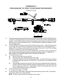
APPENDIX 3
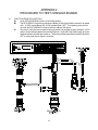
PROCEDURE TO TEST CABLES
2)
INJECTION PUMP WILL NOT RUN (continued)
A)
Ref. cable 115-0171-130 & 115-0171-138 wiring diagram (console cable & product cable).
1)
Verify 30 amp fuse is good.
2)
Verify 12 volts to fuse holder. Verify white wires connected to battery negative.
B)
Check connectors for corrosion.
C)
Verify 12 VDC at Pin A of connector of the Drive Motor. Use Pin B for the negative voltage
reference.
D)
E)
Pin B of the connector going to the Drive Motor is pulsed when the motor is running. This
is how the speed of the motor is changed. A pusle that holds pin B to 0 volts for a long time
will cause the motor to run faster than a pusle that holds pin B to 0 VDC for a short time.
Drive Motor Test
1)
Use the OHM meter function of a multi-meter to measure the resistance of the Drive
Motor. It should measure less than 3 ohms.
An other way to test the Drive Motor is to apply 12 VDC to the motor +12 VDC to pin A,
0 VDC to pin B. The motor should run at full rpm.
33
APPENDIX 4
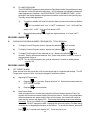
PROCEDURE TO TEST SPEED SENSOR EXTENSION CABLES
Disconnect extension cable from Speed Sensor Assembly cable. Hold extension cable connector so
that keyway is pointing in the 12 o’clock position.
PIN DESIGNATIONS
2 o’clock socket location is power if SCS Sidekick is connected to an
SCS 440 style Console.
10 o’clock socket location is ground.
6 o’clock socket location is signal.
VOLTAGE READINGS
1) 10 o’clock socket to 6 o’clock socket = +5 VDC.
2) 10 o’clock socket to 2 o’clock socket = +5 VDC.
If a +5 VDC voltage reading is not present, disconnect the Flow Sensor
cable. If the Speed reading is restored, Test the Flow Sensor cable per
Appendix "PROCEDURE TO TEST FLOW METER CABLES".
PROCEDURE TO CHECK CABLE:
l)
Enter SPEED CAL number of 9999 in key labelled:
2)
Depress key labelled:
3)
With small jumper wire (or paper clip), short between the 10 o’clock and 6 o’clock sockets with a "shortno-short" motion. Each time a contact is made, the DISTANCE total should increase by increments
of 1 or more counts.
4)
Perform above voltage checks.
5)
If DISTANCE does not increase, remove the section of cable and repeat test at connector next closest
to Console. Replace defective cable as required.
6)
If all cables test good, replace Speed Sensor.
NOTE:
After testing is complete, re-enter correct SPEED CAL number before application.
34
APPENDIX 5
PROCEDURE TO TEST METERING SENSOR CABLES
Disconnect cable from Metering Sensor. Hold Metering Sensor cable so that the keyway is pointing in the
12 o’clock position:
PIN DESIGNATIONS
2 o’clock socket location is ground.
10 o’clock socket location is power.
6 o’clock socket location is signal.
VOLTAGE READINGS
1) 2 o’clock socket to 6 o’clock socket = +5 VDC.
2) 2 o’clock socket to 10 o’clock socket = +5 VDC.
If a +5 VDC voltage reading is not present, disconnect the Speed
Sensor cable. If the Flow reading is restored, Test the Speed Sensor
cable per Appendix "PROCEDURE TO TEST SPEED SENSOR
EXTENSION CABLES".
PROCEDURE TO CHECK CABLE:
1)
Enter a METER CAL number of one (1) in key labelled:
2)
Depress key labelled:
3)
Place BOOM switches and MASTER switch of mating console to ON.
4)
With small jumper wire (or paper clip), short between the 2 o’clock and 6 o’clock sockets with a "shortno short" motion. Each time a contact is made, the TOTAL VOLUME should increase by increments
of 1 or more counts.
5)
Perform above voltage checks.
6)
If TOTAL VOLUME does not increase, remove the section of cable and repeat test at connector next
closest to Console. Replace defective cable as required.
7)
If all cables test good, replace Metering Sensor.
NOTE:
After testing is complete, re-enter correct METER CAL numbers before application.
35
APPENDIX 6
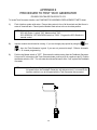
PROCEDURE TO TEST TACH GENERATOR
P/N 063-0159-784 OR P/N 063-0172-312
To locate Tach Generator location, see PUMP/MOTOR ASSEMBLY REPLACEMENT PARTS sheet.
1)
Flush injection system with water. Ensure that system is free of all chemicals and that there is
water in chemical tank. Place Injection Module hand valves to the re-circulate position.
NOTE:Position console switches as follows:
SCS 440, Boom 1 switch "ON", Master switch "ON".
SCS SIDEKICK, OFF/HOLD/RUN switch to "RUN". Program the SCS Sidekick in
manual control.
2)
Injection module should now be running. If you can change pump speed by using the
and
keys, the Tach Generator is good. If you can not, proceed to step 3. Refer to Automatic
Rate +/- in console programming.
3)
Position the Master switch to "OFF". Disconnect the cable coming from the Feedback Generator.
Connect a DC volt meter to the Tach Generator leads, positive to pin A, negative to pin B. Position
the Master switch to “ON”. The volt meter should read at least 9 volts. If not, replace the Feedback
Generator.
NOTE:
If the Feedback Generator is good and the injection module was not running at
full speed before the Feedback Generator was disconnected, it is normal for the
injection module to run at full speed with the Tach Generator disconnected.
36
APPENDIX 7
PROCEDURE TO TEST METERING SENSOR
063-0171-669 or 063-0172-351
To verify Metering Sensor location see REPLACEMENT PARTS sheet for PUMP/MOTOR ASSEMBLY.
NOTE:
A cable test should be performed on the main harness prior to testing the Metering
Sensor. A cable test is identical to the "Procedure to Test Product Flow Cables".
Disconnect the 2 pin connector of Motor from the Product Cable. This is done as a safety measure to guard
against the chance of starting the Injection Module during the test.
1)
Enter a METER CAL number of "10" in key labelled .
2)
Turn the Master Switch and Boom 1 Switch to "ON". Place the OFF/HOLD/RUN switch of the
SCS Sidekick Console to RUN
3)
Rotate printed magnet wheel by hand.
4)
Depress
and display should increment by 2 per revolution of the pump. If not, replace the
Metering Sensor.
NOTE:
If Injection Module is over-applying or under-applying product, it may be necessary to clean the intake and discharge valves. Verify programming calibration
numbers when either over-applying or under-applying.
37
APPENDIX 8
PROCEDURE TO RE-CALIBRATE PUMP
1)
Enter 50 into the METER CAL key on the SCS SIDEKICK Console.
2)
Place 3-way valve handle on Injection Pump to recirculate position.
3)
Place BOOM and MASTER switches ON. Place the OFF/HOLD/RUN switch to RUN.
4)
Run pump until liquid appears from tank return hose. Place OFF/HOLD/RUN switch to HOLD.
5)
Enter "0" into TOTAL VOLUME key.
6)
Place tank return hose into measuring container.
7)
Place OFF/HOLD/RUN switch to RUN until 50 ounces of measured product is pumped. The
number displayed in TOTAL VOLUME is the new METER CAL.
8)
Enter this new METER CAL number in METER CAL key.
9)
Enter "0" in TOTAL VOLUME key.
10)
Place OFF/HOLD/RUN switch to RUN until 50 ounces of measured product is pumped.
11)
The number in TOTAL VOLUME should be 49, 50, or 51. If not, repeat calibration procedures.
12)
Empty tank return hose into measuring container.
13)
Pour product caught in measuring container back into Injection Module Tank.
NOTE:
A. Typical causes for Injection System to
under apply are:
1.
Fouled Pump Check Valves.
2.
Air leaks on Injection Pump inlet
plumbing.
3.
Air entrained in chemical.
4.
Plugged inlet strainer.
5.
Chemical is too thick to flow thru
inlet plumbing.
B. Typical cause for over application:
Incorrect calibration data entered into
Console.
38
APPENDIX 9
PROCEDURE TO TEST FLOW MONITOR SENSOR
P/N 063-0171-979
1)
2)
3)
4)
5)
The above drawing represents the Flow Monitor Manifold found inside the RAVEN SIDEKICK pump.
In operation, the magnet shuttel moves back and forth inside the flow monitor manifold as fluid is
pumped. The Flow Monitor Sensor detects the magnet's movement when a north and south pole
pass by the face of the Flow Monitor Sensor. A red LED flashes, indicating the detection of the
moving magnet shuttel.
The SCS SIDEKICK Console monitors the Flow Monitor Sensor output. In order for the flow alarm
not to sound, the console must see a pulse from the Flow Monitor Sensor as indicated by the
flashing LED on the sensor or also indicated by the run light on the console. If the LED is in a steady
ON state or a steady OFF state, the flow alarm will be ON.
In some cases, the problem can be solved by adjusting the Flow Monitor Sensor to the left or the
right. In other cases, the magnetic shuttel may need to be cleaned. Refer to: SENSITIVITY
ADJUSTMENT PROCEDURE, MANIFOLD FLOW MONITOR SENSOR.
To test the sensor by itself:
a)
Remove the sensor from the manifold.
b)
Disconnect the 2 pin connector from the drive motor.
c)
Position the Sidekick's OFF/HOLD/RUN switch to RUN. On the SCS 440 Console, position
the Master switch and the Boom 1 switch to ON. The flow alarm on the Sidekick console
will come on.
d)
Using a magnet, alternate the north pole, then the south pole against the face of the sensor.
As the Flow Monitor Sensor detects the magnets changing polarity, verify the LED on the
sensor changes from ON to OFF. The flow alarm on the Console should also be silent as
long as the Flow Monitor Sensor's LED flashes.
The pin out of the sensor is as follows:
A = +12 VDC; B = Signal; C= 0 VDC
To test this portion of the cables, make and break a short between pins A and B. If the cable is
good, the run LED on the console will flash.
NOTE: Position console switches as indicated in step 3 above.
39
APPENDIX 10
SENSITIVITY ADJUSTMENT PROCEDURE, MANIFOLD FLOW MONITOR
SENSOR
1)
Position injection modules hand valve to recirculate. Run pump to prime system. Inspect for any
leaks. Repair as necessary.
2)
Monitor volume per minute. Manually adjust pump output to 5 oz. per minute.
3)
Visually monitor LED on manifold sensor. Adjust manifold sensor left or right until LED flashes.
Tighten screws on bracket. See below.
4)
Verify LED continues to flash.
5)
Manually adjust pump output to 40 oz/min. Verify LED continues to flash.
6)
During normal operation LED shall flash. If pump pumps on only one cylinder, LED will no longer
flash. Flow error message will be displayed on console.
7)
Return hand valve to injection position.
NOTE:To read vol/min, refer to SIDEKICK CONSOLE manual.
40
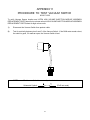
APPENDIX 11
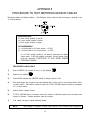
PROCEDURE TO TEST VACUUM SWITCH
063-0171-035
To verify Vacuum Sensor location see ULTRA LOW VOLUME INJECTION MODULE ASSEMBLY
REPLACEMENT PARTS sheet for low volume units or HIGH VOLUME INJECTION MODULE ASSEMBLY
REPLACEMENT PARTS sheet for high volume units.
1)
Disconnect the Vacuum Switch from product cable.
2)
Test for continuity between pins A and C of the Vacuum Switch. If the OHM meter reads a short,
the switch is good, if it reads an open, the Vacuum Switch is bad.
NOTE:
The Vacuum Switch is a normally closed circuit.
Schematic Symbol:
(Pin B not used)
41
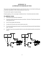
APPENDIX 12
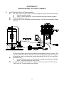
ALTERNATIVE TANK SELECTION
Tank must be of a shape and design that does not permit the tank outlet to un-cover when the vehicle goes
up and down steep grades or when sloshing when product in tank is low.
The tank should be capable of complete drainage.
Generally speaking, a tall, narrow (length and width) tank is best. Cone bottom tanks work well also.
PLUMBING TANK
1)
Pump must be gravity fed with a flooded inlet.
2)
Keep plumbing short and avoid running hose up and down. (See below) This will trap air and could
cause pump to air lock.
3)
Use 3/4" hose between tank and pump.
4)
A strainer with 20 mesh screen must be used on pump inlet.
5)
Provide for tank drainage and incorporate 3-way valves that will allow pump to be flushed with clean
water. See below.
6)
Provide a 3-way valve on pump outlet to allow for a recirculation/calibration position and an injection
position.
42
APPENDIX 13
SERIAL INTERFACE
1)
Cable pinout (P/N 115-0159-994), supplied with Thermal Printer Kit
(P/N 117-0159-529).
DSR 6
5
CTS 8
RAVEN
Printer
DTR 4
6
CONSOLE
25 Pin
TXD 3
2
9 PIN
RXD 2
3
GND 5
7
2)
Changing RATE 1 CAL by remote computer.
a)
Configuration of RS-232C serial port:
1200 or 9600 Baud Rate
NO Parity
8 Data Bits
2 Stop Bits
b)
Data stream to Raven Console.
EXAMPLE:
Change RATE 1 to 123.4
$R,RC,1234<CR><LF>
Line Feed
Communication
string
Rate Cal
RATE 1
= 123.4
Carriage Return
Decimal point is not sent from Remote Computer to Raven Console.
3)
Optional 9 pin to 9 pin cable pinout (P/N 115-0159-822).
RAVEN
CONSOLE
9 PIN
DSR 6
CTS 8
DTR 4
4
6
8
2
3
5
TXD 3
RXD 2
GND 5
43
COMPUTER/
GPS
9 Pin
APPENDIX 14
SCS-SIDEKICK COMMUNICATION STRINGS
REMOTE COMPUTER TO SCS-SIDEKICK CONSOLE
All request strings begin with $R, to indicate a Raven communication string.
Rate 1 Change Request:
$R,RC,<rate_1_cal><CR><LF>
Calibration String Values Request:
$R,CR<CR><LF>
Data String Request:
$R,DR<CR><LF>
Time Request:
$R,TR<CR><LF>
Time Acknowledge Request:
$R,TA<CR><LF>
SCS-SIDEKICK CONSOLE TO REMOTE COMPUTER
All console output strings begin with $R122A, the $R indicates a Raven communication string, the 122 is
the last three digits of the current SCS-SIDEKICK programmed chip part number and A is the software
revision number.
Calibration Strings:
$R122A,C1,<switch_byte_1>,<switch_byte_2>,<boom_1_cal>,
<boom_2_cal>,<boom_3_cal>,<boom_4_cal>,<boom_5_cal>,
<boom _6_cal>,<boom_7_cal>,<speed_cal><CR><LF>
$R122A,C2,<meter_cal>,<CR><LF>
$R122A,C3,<valve_cal>,<rate_1_cal><CR><LF>
Bit
0
1
2
3
4
5
6
7
NOTE:
Switch Byte 1 Switch Byte 2
boom 1
0
boom 2
0
boom 3
0
boom 4
rate 1
boom 5
0
boom 6
0
boom 7
0
1
1
If rate 1 is zero, the console is in Manual.
For switch Byte Bits; 0 = off and 1 = on.
Data Strings:
$R122A,D1,<total_area><CR><LF>
$R122A,D2,<total_volume><CR><LF>
$R122A,D3,<distance><CR><LF>
Actual Rate:
$R122A,AR,<actual_rate><CR><LF>
Time/Date:
$R122A,TD,<hr:min>,<month/day/year>,<field_reference><CR><LF>
44
Notes:
45
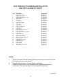
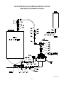
SCS SIDEKICK PLUMBING INSTALLATION
AND REPLACEMENT PARTS
ITEM
1
2
3
4
5
6
7
8
9
10
11
12
13
14
15
16
17
18
19
20
21
22
23
24
25
26
27
28
29
30
31
32
DESCRIPTION
Fitting, Elbow, Street
Valve, 3 Way 1/2” Poly
Fitting, Plug, 1/2” Poly
Fitting, Elbow 1/2” NPT x 3/4” HB
Fitting, Strainer 1/2”
Gasket, M100
Hose Clamp
Hose, EVA 3/4”
Fitting, Elbow, Flanged
Fitting, Nozzle Nipple
Check Valve
Teflon Washer
Fitting, Hose Shank 3/8”
Fitting, Nozzle Cap
Hose Clamp
Hose, EVA 3/8”
Fitting, Bushing 3/4 X 1/4 Poly
Fitting, Nozzle Body
Fitting, Elbow 1/4 NPT X 3/8 HB Poly
Cap & Gasket
Washer, Flat 1/4” SS
Washer, Lock 1/4” SS
Bolt 1/4-20 UNC X 5/8 SS
Washer, Lock Internal Tooth SS
Fitting, Elbow HB
Fitting, Nipple 1/2” X 4” SS
Bushing 3/4” X 1/2” Poly
Nut 1/4-20 Hex SS
Fitting, Flanged
Clamp, V-Band
Fitting, Nipple
Valve 3-Way Continuous Flow
RAVEN PART #
333-0007-031
334-0001-037
333-0009-063
333-0002-048
333-9000-008
219-0000-129
435-3003-003
Not Supplied in Kit
333-0002-200
333-0008-164
333-0011-001
313-2202-460
333-0002-061
333-0009-028
435-3003-002
Not Supplied in Kit
333-0003-039
333-0002-901
333-0002-040
333-0002-902
313-2301-810
313-1000-017
311-0050-202
313-3000-032
333-0002-047
107-0159-907
333-0003-071
312-1001-033
333-0002-201
435-3003-044
333-0008-154
334-0001-054
NOTES:
1.
2.
3.
This kit is intended to aid with installing Raven Injection Pumps to a non-Raven tank.
Not all fittings shown may be relevant.
Assemble parts as shown. Use pipe sealant on all fittings.
Please note valve item 41 must be installed on the outlet side of the pump for
recirculation. This valve has a blue dot in the handle for identification.
016-0159-820
46
SCS SIDEKICK PLUMBING INSTALLATION
AND REPLACEMENT PARTS
016-0159-820
47
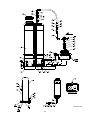
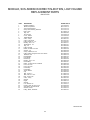
MODULE, SCS-SIDEKICK DIRECT INJECTION, HIGH
VOLUME
REPLACEMENT PARTS
063-0172-511
ITEM
1
2
3
4
5
6
7
8
9
10
11
12
13
14
15
16
17
18
19
20
21
22
23
24
25
26
27
28
29
30
31
32
33
34
35
DESCRIPTION
Weldment, Platform
Module, Pump/Motor
Tube, Formed Upright
Strap, Tank Mounting, Stainless
Bolt, J-Hook
Plug, 3/4”
Tank, 24 Gal.
Cover, Fillwell
Saddle, Molded
Valve, 3-Way
Valve, 1 PSI Check
Fitting, Nipple 1/2” x 4”
Bushing, 3/4” x 1/2”
Street Elbow, 1/2”
Plug, 1/2”
Fitting, Flanged
Elbow, 3/4” HB x 1/2” NPT
Strainer, 1/2”
Clamp, V-Band, FC-100
Fitting, Elbow, Flanged M-100 x 3/4” HB 90°
Gasket, M-100
Nozzle Nipple
Hose Shank
Nozzle Cap
Bushing, 3/4” to 1/4”
Nozzle Body
Elbow, 1/4” NPT to 3/4” Hosebarb
Hose, 3/4” EVA
Hose, 3/8” EVA
Hose Clamp
Hose Clamp
Teflon Washer
Cap
Bolt, 1/4-20 x 1”
Bolt, 5/16-18 x 1 3/4”
RAVEN PART #
116-0159-484
063-0172-428
107-0171-374
107-0171-375
321-0000-316
333-0009-064
118-0159-016
118-0159-043
118-0159-007
334-0001-037
333-0011-001
107-0159-907
333-0003-071
333-0007-031
333-0009-063
333-0002-201
333-0002-048
333-9000-008
435-3003-044
333-0002-200
219-0000-129
333-0008-164
333-0002-061
333-0009-028
333-0003-039
333-0002-901
333-0002-040
214-0001-005
214-0001-002
435-3003-003
435-3003-002
313-2202-460
333-0002-902
311-0050-105
311-0052-108
36
37
38
39
40
41
42
43
44
45
Bolt, 1/4-20 x 5/8”
Valve, 3-Way
Washer
Nipple
Washer
Lock Washer 1/4”
Hex Nut, 5/16-18, Nylon Lock
Star Washer 14mm External
Fitting, Elbow, Hosebarb
Washer, Fender
311-0050-202
334-0001-054
313-2300-012
333-0008-154
313-2301-810
313-1000-017
312-4000-059
313-3000-032
333-0002-047
313-2300-124
054-0159-314
48
054-0159-314
49
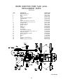
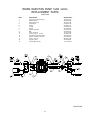
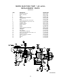
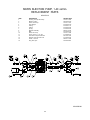
RAVEN INJECTION PUMP, 5-200 oz/min.
REPLACEMENT PARTS
063-0172-428
ITEM
1
2
3
4
5
6
7
8
9
10
11
12
13
14
15
16
17
18
19
20
21
22
23
24
25
26
DESCRIPTION
Motor/Tach Assembly
Bearing Assembly
Key
O-Ring
Bracket, Mounting, Pump/Motor
Label, Meter Cal
Strap
Washer, Internal Tooth, Lock 1/4” SS
Screw, Socket Heat, Cap 1/4”-20 x 3/4”
Cartridge, Intake
Cartridge, Discharge
Bracket, Sensor
Screw
Label, Serial
Tie, Cable
Cap, Tapered
Thread Sealant Loctite #242
Screw, Cap, Hex Socket Head 1/4-20 x 1/4
Manual (Not Shown)
Grease, Lubricating, Versilube
Bolt, 1/4”-20 x 1”
Washer
Nut
Anti-Sieze Compound, Nickel
Grease
Sensor, Universal, Flowmonitor
RAVEN PART #
063-0172-500
063-0172-501
107-0171-588
219-0001-153
107-0171-589
041-0159-718
107-0171-594
313-3000-017
311-0073-066
063-0172-503
063-0172-504
106-0159-539
311-0004-040
041-0159-710
435-1000-003
118-0159-041
222-1001-029
311-0068-060
016-0159-975
222-0000-002
311-0069-004
313-2300-009
312-4000-057
222-1001-079
222-1001-114
063-0172-525
054-0159-290
50
RAVEN INJECTION PUMP, 5-200 oz/min.
REPLACEMENT PARTS
063-0172-428
ITEM
1
2
3
4
5
6
7
8
9
10
11
12
13
14
15
16
DESCRIPTION
Housing, 3/4” Injection Pump
Bearing, Piston
Piston, 3/4” Pump
Seal, Slipper
O-Ring
O-Ring
Spring
Magnet Assembly
Ball
Head, 3/4” Pump
Screw 10-24 x 1 1/2” SS
Anti-Sieze Compound, Nickel
Washer, Internal Tooth Lock
Switch, Vacuum
Plug, Hex, Pipe
Seal Kit (Not Shown)
RAVEN PART #
107-0171-523
325-0000-018
107-0171-531
219-0000-125
219-0007-117
219-0002-015
314-0000-012
063-0172-518
321-0000-313
107-0171-526
311-0068-191
222-1001-079
313-3000-014
063-0171-035
333-0009-061
117-0159-987
054-0159-290
51
RAVEN INJECTION PUMP, 1-40 oz/min.
REPLACEMENT PARTS
063-0172-510
ITEM
1
2
3
4
5
6
7
8
9
10
11
12
13
14
15
16
17
18
19
20
21
22
23
24
25
DESCRIPTION
Motor/Tach Assembly
Bearing Assembly
Key
O-Ring
Bracket, Mounting, Pump/Motor
Label, Meter Cal
Strap
Washer, Internal Tooth, Lock 1/4” SS
Screw, Socket Heat, Cap 1/4”-20 x 3/4”
Cartridge, Intake
Cartridge, Exhaust
Bracket, Sensor
Screw
Grease
Sensor, Universal, Flowmonitor
Label, Serial
Tie, Cable
Cap, Tapered
Thread Sealant Loctite #242
Screw, Cap, Hex Socket Head 1/4-20 x 1/4
Manual (Not Shown)
Grease, Lubricating, Versilube
Bolt, 1/4”-20 x 1”
Washer
Nut
RAVEN PART #
063-0172-527
063-0172-501
107-0171-588
219-0001-153
107-0171-599
041-0159-720
107-0171-600
313-3000-017
311-0073-066
063-0172-503
063-0172-504
106-0159-539
311-0004-040
222-1001-114
063-0172-525
041-0159-721
435-1000-003
118-0159-041
222-1001-029
311-0068-060
016-0159-975
222-0000-002
311-0069-004
313-2300-009
312-4000-057
054-0159-291
52
RAVEN INJECTION PUMP, 1-40 oz/min.
REPLACEMENT PARTS
063-0172-510
ITEM
1
2
3
4
5
6
7
8
9
10
11
12
13
14
15
DESCRIPTION
Housing, 3/4” Injection Pump
Bearing, Piston
Piston, 3/4” Pump
Seal, Slipper
O-Ring
O-Ring
Spring
Magnet Assembly
Ball
Head, 3/4” Pump
Screw 10-24 x 1 1/2” SS
Anti-Sieze Compound, Nickel
Washer, Internal Tooth Lock
Switch, Vacuum
Plug, Hex, Pipe
RAVEN PART #
107-0171-523
325-0000-018
107-0171-531
219-0000-125
219-0007-117
219-0002-015
314-0000-012
063-0172-518
321-0000-313
107-0171-526
311-0068-191
222-1001-079
313-3000-014
063-0171-035
333-0009-061
054-0159-291
53
MODULE, SCS-SIDEKICK DIRECT INJECTION, LOW VOLUME
REPLACEMENT PARTS
063-0172-512
ITEM
1
2
3
4
5
6
7
8
9
10
11
12
13
14
15
16
17
18
19
20
21
22
23
24
25
26
27
28
29
30
31
32
33
34
35
36
37
38
39
40
41
42
43
44
45
DESCRIPTION
Weldment, Platform
Module, Pump/Motor
Tube, Formed Upright
Strap, Tank Mounting, Stainless
Bolt, J-Hook
Plug, 3/4”
Tank, 24 Gal.
Cover, Fillwell
Saddle, Molded
Valve, 3-Way
Valve, 1 PSI Check
Fitting, Nipple 1/2” x 4”
Bushing, 3/4” x 1/2”
Street Elbow, 1/2”
Plug, 1/2”
Fitting, Flanged
Elbow, 3/4” HB x 1/2” NPT
Strainer, 1/2”
Clamp, V-Band, FC-100
Fitting, Elbow, Flanged M-100 x 3/4” HB 90°
Gasket, M-100
Nozzle Nipple
Hose Shank
Nozzle Cap
Bushing, 3/4” to 1/4”
Nozzle Body
Elbow, 1/4” NPT to 3/4” Hosebarb
Hose, 3/4” EVA
Hose, 3/8” EVA
Hose Clamp
Hose Clamp
Teflon Washer
Cap
Bolt, 1/4-20 x 1”
Bolt, 5/16-18 x 1 3/4”
Bolt, 1/4-20 x 5/8”
Valve, 3-Way
Washer
Nipple
Washer
Lock Washer 1/4”
Hex Nut, 5/16-18, Nylon Lock
Star Washer 14mm External
Washer, Fender
Fitting, Elbow, Hosebarb
RAVEN PART #
116-0159-484
063-0172-510
107-0171-374
107-0171-375
321-0000-316
333-0009-064
118-0159-016
118-0159-043
118-0159-007
334-0001-037
333-0011-001
107-0159-907
333-0003-071
333-0007-031
333-0009-063
333-0002-201
333-0002-048
333-9000-008
435-3003-044
333-0002-200
219-0000-129
333-0008-164
333-0002-061
333-0009-028
333-0003-039
333-0002-901
333-0002-040
214-0001-005
214-0001-002
435-3003-003
435-3003-002
313-2202-460
333-0002-902
311-0050-105
311-0052-108
311-0050-202
334-0001-054
313-2300-012
333-0008-154
313-2301-810
313-1000-017
312-4000-059
313-3000-032
313-2300-124
333-0002-047
054-0159-315
54
054-0159-315
55
Notes:
56
RAVEN INDUSTRIES
Limited Warranty
What Does this Warranty Cover?
This warranty covers all defects in workmanship or materials in your
Raven Applied Technology Product under normal use, maintenance,
and service.
How Long is the Coverage Period?
Raven Applied Technology Products are covered by this warranty for
12 months after the date of purchase. This warranty coverage applies
only to the original owner and is nontransferable.
How Can I Get Service?
Bring the defective part and proof of purchase to your Raven Dealer.
If your Dealer agrees with the warranty claim, the Dealer will send the
part and proof of purchase to their distributor or to Raven Industries
for final approval.
What Will Raven Industries Do?
Upon confirmation of the warranty claim, Raven Industries will, at our
discretion, repair or replace the defective part and pay for return
freight.
What is not Covered by this Warranty?
Raven Industries will not assume any expense or liability for repairs
made outside our facilities without written consent. Raven Industries
is not responsible for damage to any associated equipment or
products and will not be liable for loss of profit or other special
damages. The obligation of this warranty is in lieu of all other
warranties, expressed or implied, and no person or organization is
authorized to assume any liability for Raven Industries.
Damages caused by normal wear and tear, misuse, abuse, neglect,
accident, or improper installation and maintenance are not covered
by this warranty.
SCS Sidekick Injection System
Installation & Service Manual
(P/N 016-0159-819 Rev G 7/09)
Raven Industries
Applied Technology Division
P.O. Box 5107
Sioux Falls, SD 57117-5107
Toll Free (U.S. and Canada): (800)-243-5435
or Outside the U.S. :1 605-575-0722
Fax: 605-331-0426
www.ravenprecision.com
[email protected]
Notice: This document and the information provided are the property of Raven Industries, Inc. and may only be used as authorized
by Raven Industries, Inc. All rights reserved under copyright laws.