1
Installation
Instructions
For Marelli EFI
Conversion
With AutoTune
Closed Loop
READ ALL INSTRUCTIONS FIRST! If you do not have a H-D® service manual for the year and
model of the motorcycle you are working on, get one before starting the installation to use for
reference. The factory ECM you are replacing is triggered by signals from the cam position and
crankshaft position sensor (CPS), while the ThunderMax, like the later Delphi® system, uses only
the signal from the crankshaft position sensor. We recommend disconnecting the cam position
sensor and installing a new crankshaft sensor and in-tank fuel filter on your (at least) 11-year old
motorcycle during installation. Verify charging system operation and battery condition; check
both ends of battery cables for clean, tight connections. See Pages 7&8 for special procedures
regarding certain model years. This product is legal in California only for racing vehicles which
may never be used upon a highway.
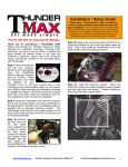
1.
Disconnect the battery
terminal
before
positive
proceeding to step one. Remove
the Marelli intake assembly from
the engine. Remove also the
top engine mount with the
stabilizing link attached to it.
rail fitting using supplied EFI
hose clamp (the hose and
clamps supplied are special high
pressure
EFI
compatible
components, NEVER replace
these with standard hose or
clamps).
2. The new ThunderMax throttle
body and manifold assembly are
pre-assembled as delivered.
Remove the intake manifold
assembly from the throttle body.
3. Install the manifold assembly
using lightly lubricated new
intake seals (supplied) and the
original intake flanges.
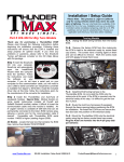
4. Remove the stabilizing link
from the top engine mount,
noting which side of the link was
attached to the engine mount.
Re-mount the link to the chassis
mount using the supplied 3/8-24
button head bolt, 12pt nut and
original washer under the nut as
shown (nut up). Tighten to 40
ft/lbs.
8. Grasp the fitting with pliers
and twist the line loose from the
fitting
and
separate
it.
6. The original fuel lines will be
retained, but the banjo ends
must be removed. Using a pair
of dial calipers, mark the
crimped factory fitting .210” from
the crimp housing.
7. Using a tubing cutter, cut
through the crimped end.
5. Attach supplied special high
pressure 5/16” EFI hose to fuel
9. Remove the remaining ring
from the rubber hose. Repeat
this process on the 2nd hose.
13. Install throttle cables and
throttle body assembly. Attach
harnesses for TPS, MAT sensor
and IAC motor. Adjust throttle
cables for proper closed freeplay and idle to wide-open
operation.
10. Attach the fuel supply and
return hoses to the manifold
using the supplied EFI clamps.
14. Verify clearance between
buttonhead stabilizing link bolt
and IAC motor plug.
11.
Place the manifold in
location under the stabilizing
link; align with supplied 3/8-16
hex bolt. Route EFI hose from
fuel rail to fitting (arrow) on
manifold block (trim for best fit;
allow
gentle
loop
without
permitting hose to kink or touch
cylinder fins).
Attach with
provided EFI hose clamps.
Installing With AutoTune
15. Install air cleaner (follow
instructions included with air
cleaner kit).
16. Install fuel tank. Re-attach
fuel hoses to tank.
12. Re-install top engine mount
with link using provided 3/8-16
hex bolt and existing nut and
washers on left side (tighten to
40
ft/lbs);
use
supplied
buttonhead bolt and 12pt nut for
the right side link (nut on top).
18. Remove factory ECM and
replace
with
supplied
ThunderMax ECM (1995-1996
model years, perform ground
wire addition explained on page
8 before installing ECM). Route
communication cable plug to
allow for easy access. After the
ECM is plugged in, connect the
battery positive cable, then
install the new ECM Power
Relay. If the lights come on or
the fuel pump runs upon relay
connection, the wrong relay was
replaced in step 17 (correct this).
17. For steps 17 & 18 the
battery positive cable should
still be disconnected. There
are several relays in the wiring
system. Locate and remove the
“ECM Power Relay” usually
under seat. This will be replaced
with supplied relay AFTER the
battery cable is reconnected.
This specially modified relay is
configured with a “stay alive”
circuit, required for your new
ECM. 2000-2001 models, see
special instructions on page 7
before proceeding.
19. If the exhaust system you
are using is not equipped with
oxygen sensor bungs, bungs will
need to be added to the exhaust
pipes. Bungs must be located
within 3”-6” from the cylinder
head. Install supplied wide band
oxygen sensors in the front and
rear exhaust pipes. Route and
tie down the sensor harnesses
away from the engine.
20. To mount the closed loop
module, pick a suitable location
that will allow the power/data
plug to easily reach the bike’s
diagnostic port plug, and allow
the oxygen sensor harnesses to
reach the sensor plugs. Secure
with wire ties or 2-sided foam
tape (orientation of the module is
not important).
Connect the
sensors to the closed loop
module.
The sensor wiring
harness for the rear cylinder
sensor is shorter and can be
easily identified by black
tracers on all of its wires. It is
very important to install this
correctly or the engine will
perform poorly!
Special Procedure
for AutoTune Wiring
on Marelli Bikes:
Your AutoTune module is
designed to communicate with
the ThunderMax through the
bike’s Data Link connector. This
port is also where the AutoTune
draws its power. However, on
1997-2001 model Big Twins, the
12 volt terminal (#4 in the Data
Link plug) is “hot” at all times,
not upon “key-on” as are 2002
and later (Delphi) bikes. The
Data Link must be rewired to
provide power for the AutoTune
module only when in the “keyon” position or battery drain will
result.
To rewire this plug: Identify the
“Accessory” plug, located under
the seat nose, just below and to
the right of the frame’s backbone
where it intersects with the frame
side rails. This plug has 4 wires
routed to it. Locate the blue wire
in the #1 position.
Remove the rubber seal plug
(or, if there are any accessories
plugged into the accessory port,
temporarily
unplug
the
accessory). Remove the socket
lock and push the #1 terminal
and wire out of the plug. Clip off
the terminal end and install a
new (supplied) terminal on the
blue wire along with the supplied
length of orange wire (crimp
together). Reinstall the terminal
Confirm that a base map was
loaded into your module by
Zipper’s for your application:
____ Base Map NOT Loaded
____ Base Map Loaded
Map # _________
Your Data Link plug will now be
wired “hot” through the key
switch.
You may choose to source your
“key-hot” wire from another
location; certainly your choice.
Whatever you choose, the wire
in the #4 Data Link plug must be
changed to a “key-hot” wire or a
dead battery will be the result.
21. Plug the closed loop module
into the power source (Data
Link) on the bike. It is through
the data port that data from the
AutoTune module is transferred
to the ThunderMax.
A ‘Y’
harness is available to keep an
open data port if desired.
SPECIAL PROCEDURE
REQUIRED FOR ECM
INITIALIZATION
UPON
FIRST
TIME
KEY-ON
POWER-UP!
See Step
24.
Before starting the
engine for the first time,
Thoroughly check
motorcycle for:
into the #1 port of the accessory
plug and reassemble the plug.
Remove the lock from the Data
Link plug and push the
red/orange wire and terminal
from the #4 position. Route the
orange wire from the accessory
plug to the Data Link plug.
Crimp the supplied terminal to
the orange wire and install it into
the Data Link #4 plug. Cover the
end of the original red/orange
“hot” wire terminal end, and tuck
the covered terminal into the
harness sleeve.
Fuel leaks at all line connections
including the pressure regulator
block, fuel rail fittings and all
hose connections; tight battery
and ground connections; proper
throttle cable adjustment (throttle
closes and opens fully with
proper free-play), smooth throttle
operation (ensure that the
throttle returns to the idle
position
quickly
and
automatically), and a full fuel
tank with fresh high-test fuel.
Perform the next steps after all
systems have been verified as
operational from re-assembly.
If a base map was loaded by
Zipper’s, skip step 23.
22. Insert the SmartLink CD into
your computer. SmartLink will
automatically
open
the
InstallShield Wizard when the
computer finds the CD-Rom.
Follow the instructions and
install the software on your
computer.
After installation,
attach the serial cable to your
computer and the ThunderMax
ECM. (If you do not have a
serial port on your computer for
the communication cable, you
will need to use a USB to Serial
converter;
an
inexpensive
converter is available from
Zipper’s, #372-000. Install the
drivers at this time; follow the
instructions
given
by
the
manufacturer of the converter.)
Make certain that the cable is
routed away from any part of the
motorcycle that generates heat.
23. If a base map was NOT
loaded, select and load a base
map that best matches your
engine
combination
and
exhaust. Install the SmartLink
software to your hard drive, open
the software and consult the
SmartLink Tuning Manual by
clicking on the [Help] menu on
the toolbar, then [SmartLink
Tuning Manual].
Proceed to
section 3 and follow the
instructions for choosing and
loading a base map. After the
base map is loaded, while
linked, go to the Tuning Tree,
select [Module Configuration]
[Basic Settings] and click on
[Speedo Cal] and set this to
4352. Close the [Basic Settings]
window and click [Configure] on
the toolbar, then click [Closed
Loop MODULE Settings] and
verify that the “Closed Loop
Processing” boxes are checked
in both the MAP and MODULE
sides of this window.
24. “Initialize” the ThunderMax
ECM. With the handlebar switch
in the ‘ON’ position, cycle the
key switch on and off 3 times,
leaving the ignition on for 30
seconds each cycle. DO NOT
start the engine or move the
throttle at this point. During this
time, the fuel pump will also
prime and pressurize the
system. Check the system for
fuel leaks again. After 3 on/off
cycles, start the bike 2 times, let
it settle at idle for 10 seconds;
the idle should be smooth and
even. If so, shut down and
proceed to Step 25.
Note:
Anytime the processor has
been powered down (battery
or
special
ECM
Relay
disconnected) the ECM will
need to be re-initialized in the
manner mentioned above.
25.
Open the SmartLink
software package by selecting
the icon placed on your desktop.
The following picture is what will
appear when SmartLink opens
for the first time.
26. Turn the key switch to the
“Ignition”
position,
making
certain the “RUN / OFF” rocker
switch (Kill Switch) on the
handlebar controls is in the
“RUN” position.
27. Select the “Link” Button in
the SmartLink software.
Settings] on the SmartLink
toolbar. This will copy the map
file loaded into SmartLink with
the map file loaded into the
ThunderMax ECM.
29. Before restarting the engine,
from toolbar click [Monitoring]
[Show Gauges]. The “Engine
Speed”, “Engine Head Temp”,
“IAC Position”, “AFR Front”, AFR
Rear” and “AFR Target” gauges
are automatically formatted and
are shown on the screen.
Additional gauges can be
created
if
desired
(see
SmartLink Tuning Manual under
Help menu), but the above
gauges are most helpful during
initial set up. You may select
any gauges that you deem
important; if too many are
chosen your screen may appear
cluttered. Experiment with the
gauges but always display the
gauges mentioned above.
30. Select the “Monitor” button
to active the gauges. It is located
beside the “Link” button and will
turn green when the monitor
gauge function is live. The
gauges will be displayed if they
were not already on the screen.
CLICK TO SELECT
31. Now select the IAC Stops
vs. Engine Temperature page.
Strike the spacebar to show the
actual values of the tuning block.
28. Read the map that is
installed in the ThunderMax
ECM by selecting [File] then
[Read
Module
Maps
and
32.
Make certain that the
motorcycle is in Neutral and the
engine is cold, then start the
engine. If the engine idle is
stable after 10-15 seconds, shut
the engine off and re-start it
twice more. Once the engine
idle is stable after 15- 20
seconds, select the “IAC-Auto”
button (Idle Air Control Auto
Adjustment). Allow the “IACAuto” function to run at idle until
the engine head temperature
reaches 275 degrees.
After
reaching temperature of 275
degrees, the “IAC-Auto” function
automatically shuts off. You can
terminate this function at any
time, and re-run it at a later time
if you wish.
33.
Unlink
the
SmartLink
software from the ECM (click the
green [Link] button, turns red
indicating unlinked from ECM),
and physically remove the
Communication Cable from the
ThunderMax ECM.
WARNING: ANY TUNING
OPERATION INVOLVING
ACTUAL OPERATION OF
THE MOTORCYCLE ON
PUBLIC STREETS OR
HIGHWAYS
IS
DANGEROUS!
FULL
ATTENTION TO TRAFFIC
CONDITIONS
SHOULD
ALWAYS
BE
YOUR
FIRST FOCUS ANYTIME
YOU ARE OPERATING A
MOTORCYCLE
ON
PUBLIC
ROADS.
INATTENTION
TO
CONDITIONS CAN LEAD
TO ACCIDENTS AND
PERSONAL
INJURY
INCLUDING DEATH.
CLOSED LOOP
PROCESSING
Your
ThunderMax
was
programmed for closed loop
processing during the map
loading
process.
Your
SmartLink software will allow
you to set Air/Fuel tuning
parameters for your ThunderMax
and its installed base map when
the AutoTune module is installed
and AutoTune program is
enabled. To set Target AFR and
AutoTune Limits, go to the
toolbar and click [Configure]
[Close
Loop
MODULE
Settings].
The Closed Loop Configuration
dialog page opens (above); the
right side shows the default MAP
settings stored in the MAP file
(settings are applied to the
installed base map during the
‘Closed Loop Format’ conversion
performed by SmartLink), while
the left side shows what the
module is currently set to
(unadjusted, these settings will
mirror MAP’s settings).
The
un-highlighted
left
‘MODULE’ side of the page
allows editing of those settings
within the module for tuning
purposes.
To edit module
settings, click the [Link/Read
(Module)] button (left side
highlights/active). You can now
edit these settings within the
module should you want to
change any of the settings from
the ‘MAP’ default settings.
Closed
Loop
Processing
(Module) – Check [ON] to
enable closed loop processing.
During closed loop processing,
the
ThunderMax
module
processes feedback from the
oxygen sensors to adjust the fuel
volume at all points by creating
“offset” pulse width values from
the installed ‘base map’ fuel
values (points). The ‘static’ base
map is dynamically used by the
ThunderMax module and the
AutoTune’s active (closed loop)
feedback system. This system
optimizes the fuel points to fit the
target air/fuel ratio through
‘learned offset points’. These
‘learned offset points’ are stored
within the ThunderMax and are
used in conjunction with the
base map. The ‘base map’ fuel
points are not being adjusted by
either
the
AutoTune
or
ThunderMax modules.
AutoTune (Module) – Check
[ON] to allow the AutoTune
module to provide data used for
AFR adjustments via map point
offsets mentioned above. Unchecked, fuel points will be
adjusted to the last learned
offset points, or if no learning
has occurred, to the original
base map points.
Air
Fuel
Ratio
Override
(Module) – You can specify an
across-the-board AFR that the
ThunderMax will adjust to.
Clicking this box and changing
this number overrides ALL
‘Air/Fuel Ratio vs. TPS’ pages at
all RPM’s. To target specific
Air/Fuel Ratio RPM ranges and
throttle positions, leave this box
unchecked
and
edit
the
individual ‘Air/Fuel-TPS @ rpm’
map pages located under the
‘Tuning Maps’ tree.
ldle Air Control Override
(Module) - Check [OFF]. This
setting should not be checked on
except
for
diagnosing
a
particular type of supported
problem or during tuning on a
load cell dyno. Changing this
setting will lead to starting and
idling problems.
Maximum CLP Offset (Module)
– [Session (Module)] button
sets the AFR maximum learning
correction from the base map’s
fuel setting per session by
percentage (range is 0-10%). A
‘session’ is defined as the period
of time from engine on to engine
off (per cycle).
[Maximum
(Module)] button sets the total
AFR
maximum
learning
correction from the base map’s
fuel setting by percentage
(regardless
of
number
of
sessions; range is 10-25%).
Unless your application is a
considerable mismatch to the
installed base map, the default
settings of 5 and 20 percent are
sufficient
for
most
AFR
corrections.
You should always pick the best
possible map match during the
selection of your base map. The
theory behind this is to reduce
the range and time the closed
loop system needs to learn
offsets (corrections) for the
target AFR.
If your map
selection is a poor match to the
application, the amount of
learning
needed
will
be
significant.
Review
the
parameters of your base map vs.
available base maps under
‘Base Maps Listing’ to ensure
you have the best map match
and the latest version of the
map.
TIPS AND GENERAL INFORMATION
Several support features are located under the [Help] menu:
o A comprehensive tuning manual
o Links to allow transmission of module and map data via E-mail directly to ThunderMax support
o Links to allow transmission of monitor logs (recorded riding sessions) via E-mail directly to
ThunderMax support
o Links to Thunder-Max.com web site for support documents and videos
TMax Control Center provides a snapshot of AutoTuned fuel flow adjustments, RPM time logs in increments of
100 RPM’s, engine temperature logs and diagnostic codes. Valuable information about the condition of your tune
and how you ride. AutoMap, located within the TMax Control Center, feature creates a custom base map based
on AutoTuned fuel flow adjustments. Create a custom base map with just a few clicks!
When the SmartLink program is opened, it will automatically retrieve and open the last map that was open.
Any time you link to your motorcycle: Read the map that is installed in the ThunderMax ECM by selecting [File]
then [Read Module Maps and Settings] on the SmartLink toolbar. This will synchronize the map file loaded into
the ThunderMax ECM with the SmartLink software.
Accel Fuel is be used to tune throttle response (go to [Module Configuration] [Basic Settings]).
AFR Correction vs. Engine Temperature page is used to adjust warm-up AFR’s. If the engine requires more fuel
during warm-up (start to 200°), use this function to adjust. See SmartLink Tuning Manual for procedures.
AFR vs. Engine Temperature - During warm-up, the AFR on both cylinders will show richer than the target AFR at
operating temperatures; this is a normal part of the warm-up map. No permanent changes to AFR targets and
adjustments are made below 200 degrees. See SmartLink Tuning Manual for applications and procedures.
Air/Fuel-TPS @ RPM These pages reflect selected targets of AFR to throttle position at every 256 RPM when
system is in closed loop. Example: if you desire a leaner mixture for added fuel economy then you can easily make
multi-tiered AFR targets at specific throttle positions and RPM’s that will be learned during riding sessions.
During warm-up, the AFR on both cylinders will be richer than the target AFR at normal operating temperatures;
this is a normal part of the warm-up map. AutoTune and its targets are inactive below 200 degrees.
Writing new or modified maps to the module requires the system to be re-initialized, and any existing learned fuel
and IAC adjustments to be cleared (Map Editing, clear). Linking and editing an existing map within the module
does not require above steps.
System Updates are available through SmartLink with an internet connection. Software, Firmware and Map
updates can be downloaded; check frequently for updates.
In-Tank Fuel Filters should be inspected as a part of routine maintenance. The filter is small and one bad load of
fuel can clog it. The factory recommended service interval is 25K miles.
Fuel Pressure Should Be Checked during periodic service; this is also the first thing to check should you
experience sudden or gradual decreasing performance. For any EFI system to operate properly, your fuel system
should build and maintain 55-62 PSI of fuel pressure; your dealer can perform this simple test quickly.
The factory ECM you are replacing is triggered by signals from the cam position and crankshaft position sensors,
while the ThunderMax uses only the signal from the crankshaft position sensor. We recommend disconnecting the
cam position sensor, and installing a new crankshaft position sensor and in-tank fuel filter on your (at least) 11-year
old motorcycle during installation. Verify charging system operation and battery condition; check both ends of
battery cables for clean, tight connections.
Save your edited maps to your hard drive using the [Save As] command. Document the changes in [Map Notes]
located under [EFI Maps on the toolbar. These notes are stored with the saved map; remember to edit them when
making changes for future reference.
DON’T unplug the ECM without first removing the “System Relay”. “Hot Swapping” the module can damage the
electronics by spiking the circuits. Don’t forget to reinitialize the IAC using step 24 above any time power is
interrupted to the ECM.
DON’T attempt to program the ECM or start the engine when the ECM is in any position other than its natural
installed position. There is a bank angle switch within the ECM that will interrupt power, corrupting programming.
Oxygen Sensor Care Items that can damage or shorten the life of your sensors:
• Leaded fuel – Race fuel
• Oil deposits from oil consumption problems
• Excessive moisture exposure
• Extreme heat
Damaged sensors will have a significant effect to the performance of the motorcycle and should be replaced.
Replacement sensor P/N is 309-355.
Special Procedures For Certain Year Installations
2000 and Early Model 2001 Motorcycles – Page 7
1995-1996 Model Motorcycles – Page 8
2000 and Early Model 2001 Motorcycles
For the year 2000 and some early 2001 FL models, the Vehicle Speed Sensor (VSS) signal output wire from the
speedo terminates at the 8-pin main harness connector (see illustration below), #8A, pin 5. There is no connection
from there to the ECM and therefore no VSS signal to the ECM. This lack of data renders the ThunderMax’s
Automatic Idle Air Control Correction features inoperable and must be corrected. For late-year 2001 FL models,
this same VSS signal output is continued to the ECM from connector #8- pin 5 to ECM pin 8 (White/Green color
wire, no modification required). Simply view the Main Harness Connector to verify if the wire is needed.
The VSS wire is added to the harness as follows;
1. Remove the ECM relay and unbolt the ECM bracket from the bike.
2. Disconnect the main harness from the ECM and pull the rubber boot back to expose the ECM connector. Clip
any wire ties and remove the screw that secures the plastic terminal cover and remove the cover.
ECM
Connector
Main Harness
View from 2000 FLT
shop manual.
2001 year view is
similar with connector
#8 near the center of
the ECM and a relay
bank present.
Main Harness
Connector #8
3. Slide a common plastic wire tie through the plastic main harness cover toward the ECM connector. (See Fig.
A-32, Main harness to ECM harness [8]) Using a piece of tape, attach 2” of the new wire to the wire tie and
carefully pull it through the plastic wire cover. From there it can easily be routed with the existing wires to connector
#8B, pin 5. Use a magnifying glass if necessary to identify terminal location (numbers are on connector).
Terminals 72326-95 (ECM) and 72191-94 (Main Harness Connector) are included; identify the correct terminals
and use the correct tool to crimp the terminals on the wire.
NOTE: Alternately, the new wire may be routed outside of the plastic harness cover and wire tied to the harness.
4. Separate connector #8 and remove the plastic retainer and rubber seal from side B where the terminal will be
installed (carefully pry out with a small screwdriver). Use care to insert the new wire terminal into the pin 5 opening
so that it’s positioned correctly. Replace the plastic retainer then re-install the seal last so as not to twist or damage
it. Re-connect connector ends 8A to 8B.
5. Insert the ECM end of the new wire into the ECM connector pin 8 and replace the cover. Use wire ties as
needed. Use care when inserting the new terminal so that it’s positioned the same as the existing terminals. Note
the tabs on the terminal which lock into the connector. Make sure they are tapering outward and not flattened.
See Next Page For 1995-1996 Model Instructions
Page 7
Special Procedures For Certain Year Installations
1995-1996 Model Motorcycles
1995 and 1996 model motorcycle must have a ground wire added to the main ECM terminal
connector at Pin 33 (standard on 1997-2001 models). Parts required are (1) terminal connector
H-D # 72326-95 and a length of black wire.
Crimp the terminal end to the wire and add the wire to the open port #33 on the main harness
connector. Attach the other end to a suitable ground source or carefully splice it to the black
wire located at pin 34 (see diagram below).
Once this ground wire is added, proceed with step 20.
6655-A Amberton Drive
Elkridge, MD 21075
Phone 410.579.2828
Fax
410.579-2835
Page 8
[email protected]
www.Thunder-Max.com
11-15-11