1
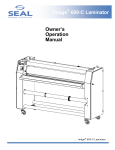
AquaSEAL SW-5000 Seal Brands … the finishing touch. Owner’s Operation Manual Important: Read and understand all safety information before operating. AquaSEAL SW-5000 Liquid Laminator Preface This manual contains the following Sections: Section 1. Introduction – provides a basic overview of the AquaSEAL™ Superwide liquid laminator, and contains illustrations of the basic hardware components. Section 2. Operating Procedures – describes procedures for setting up, starting, stopping, and controlling the machine. Section 3. Periodic Maintenance – provides procedures for periodic cleaning of the applicator area, and general cleaning. Section 4. Troubleshooting/After Sales Support – describes problems that may be encountered, lists corrective actions to resolve them, and information on who to call for after sales support. 1 Table of Contents General Warranty Statement ……………………………………………………………… 3 Safety Information ……………………………………………………………….. 4-5 Safety Labels …………………………………………………………………….. 5 Section 1. Introduction Hardware Overview ……………………………………………………………… 6-10 Section 2. Operating Procedures Tools / Supplies Needed ………………………………..……………………… 11 Loading the Sealant ……………………………………………………………… 11 Priming the Pump ………………………………………………………………... 12 Loading the Media………………………………………………………………... 13 Pre-heat the Laminator ……………………………..…………………………… 13 Web the Laminator ………………………………….…………………………… 14 Run the Laminator ………………………………….……………………………. 15 Cleaning the Laminator……………………………..……………………………. 16 Section 3. Periodic Maintenance Level 1 Cleaning …………………………………………………………………. 17 Level 2 Cleaning ………………………………….……………………………… 18 Section 4. Troubleshooting/After Sales Support Troubleshooting …………………………………..……………………………… 19-20 After Sales Support……..……………………….……………………………….. 21 2 Warranty SEAL® Graphics warrants to the original consumer purchaser that each new SEA L® Image® Laminator, which proves defective in materials or workmanship within the applicable warranty period, will be repaired or, at our option, replaced without charge. Effective November 1st, 2002 the applicable warranty period for New Equipment shall be one year (parts), six months (labor and rollers) from date of purchase. This warranty extends to and is enforceable by only the original consumer purchaser, and only for the period (during the applicable term), which the product remains in the possession of the original consumer purchaser. "Original consumer purchaser" means the person who first purchased the product covered by this warranty other than for purpose of resale. This warranty does not apply if it is found that at any time the equipment has not been used for its intended purpose. Effective November 1st, 2002 the applicable warranty period for Refurbished Equipment shall be ninety days (parts and labor, excluding rollers). Rollers are not covered under warranty. The applicable warranty period for Demo Equipment shall vary, not exceeding the maximum warranty period stated herein. All Demo Equipment comes with a specific warranty, which will be stated at the time of purchase. If warranty period is not detailed in writing, there is no remaining warranty. Please ask your dealer, distributor, or sales representative for details. NOTE: Used and Not Refurbished Equipment is sold on an “AS IS” basis with No Warranty. For more information regarding this warranty, please contact your distributor. WARNING! Any unauthorized changes or modifications to this unit without our prior written approval will void the user’s warranty and will transfer health and safety obligations to the user. WARNING! Changes or modifications to this unit not expressly approved by the party responsible for compliance could void the user's authority to operate the equipment NOTE: This equipment has been tested and found to comply with the limits for a class A digital device, pursuant to part 15 of the FCC rules. These limits are designed to provide reasonable protection against harmful interference when the equipment is operated in a commercial environment. This equipment generates uses and can radiate radio frequency energy and, if not installed and used in accordance with Owner’s Manual, may cause harmful interference to radio communications. Operation of this equipment in a residential area is likely to cause harmful interference in which case the user will be required to correct the interference at their own expense. ©Copyright SEAL® Graphics 2002 All rights are reserved. No part of the document may be photocopied, reproduced, or translated to another language without the prior written consent of SEAL Graphics. The information contained in this document is subject to change without notice and should not be construed as a commitment by SEAL Graphics. SEAL Graphics assumes no responsibility for any errors that may appear in this document. Nor does it make expressed or implied warranty of any kind with regard to this material, including, but not limited to, the implied warranties of merchantability and fitness for a particular purpose. SEAL Graphics shall not be liable for incidental or consequential damages in connection with, or arising out of the furnishing, performance, or use of this document and the program material, which it describes. Trademarks Credits SEAL® is a registered trademark of SEAL Graphics. Image® is a registered trademark of SEAL Graphics. AquaSEAL® is a registered trademark of SEAL Graphics. ProSEAL® is a registered trademark of SEAL Graphics. 3 Safety Information Intended Use The AquaSEAL™ SW-5000 liquid laminator is intended for use with medium, large, and grand format graphic output Graphics can vary in widths from 0.3–5M (1–16 ft.) in width and can be up to 90M (295 ft.) in length (dependent on thickness of media used). The AquaSEAL™ SW-5000 liquid laminator is intended for use with AquaSEAL™ water based sealant only. Use of solvent-based or other manufacturers’ sealants may damage the machine and may void any warranty. Safety Instructions Caution When handling any chemical products, read the manufacturers’ container labels and the Material Safety Data Sheets (MSDS) for important health, safety, and environmental information. To obtain MSDS Sheets for AquaSEAL™ Products, Please call your local distributor. In case of emergency, please telephone: +44 (0)1268 530 331 Europe, or (800) 486-5602 USA When using any equipment, always follow the manufacturers’ instructions for safe operation. Warning Avoid contact with heat source during use. Wear heat resistant gloves and safety glasses. Failure to avoid contact with hot surfaces may cause burns. Always observe manufacturers’ recommendations when handling chemicals. 4 Safety Information General q Do not operate the machine until it is connected to the proper power source. Refer to Installation instructions located inside control cabinet. q It is strongly recommended that the machine is fed from an “Earth Leakage” protected electrical outlet – if in doubt, please contact Hunt Technical Services (contact details in “After Sales Support” section at the rear of the manual) or consult a licensed electrician. q Familiarize yourself with the layout of the Control Panel, and with the operation of the sealant delivery system. q Do not wear loose clothing, and contain loose hair to avoid becoming entangled with moving parts of the machine. q Comply with all safety warning signs, labels, and instructions. q Operators should be trained on the proper use of the machine and all safety procedures. q Provide fresh water, clean towels and rubber gloves for use during cleanup. q It is advisable to wear eye protection when filling/emptying sealant tank. Always Provide an approved emergency eyewash station adjacent to the machine. Figure S-1 shows the safety labels that appear on the AquaSEAL™ SW-5000. Pinch Point warning labels Temperature warning label Figure S-1. Safety Labels 5 Section 1. Introduction The AquaSEAL™ SW-5000 is a medium, large, and grand format media liquid laminator used to coat graphics with a protective sealant. Operating either roll or fan fed, the media is threaded through the applicator mechanism, under the drying assembly, and onto the take-up roller. During operation, the liquid laminator applies sealant onto the printed graphics and then cures and dries it before winding the media onto the take-up roller. Hardware Overview Figure 1-1 shows the front view of the liquid laminator. Major components (safety items shown in red) include the following: Applicator Tube Web Idler Tension Idler Draw Down Assembly Dryer Panel Meyer Bar Assembly Control Panel Safety Interlock Switch Emergency Stop Figure 1-1. Front View 6 Section 1. Introduction q Four Emergency Stop Buttons are fitted to the machine, located prominently on the front of both end cabinets and on the left and right of the machine on top of the Heater assembly. When pressed, all power is removed from the working parts of the machine and all pneumatic assemblies return to their safe state. The machine cannot be used again until the Emergency Stop Buttons are reset twisting the button ¼ turn clockwise. When the emergency stop buttons are reset, the laminator powers up in the STOP mode. q The Photo Eyes are located on both right and left side plates directly in front of the Draw Down Assembly and directly in front of and behind the Heater Assembly. Both the Draw Down and Heater Assemblies are on Pneumatic cylinders that lift them up for webbing the machine. The Photo Eyes are activated when machine is switched to Run mode. The Drawdown Assembly Photo Eyes are active for 10 seconds after the Run button is pushed and then become disabled for the liquid flow adjustment. The Heater Assembly Photo Eyes always enabled in the Run Mode and raise the assembly only when the beam is crossed, and will lower when obstruction is removed. q The Draw Down Assembly is located directly over the Drain Tank and is used to apply and smooth the coating onto the surface of the media. It is in the Down position in Run mode only. It is automatically lowered when the machine is put into Run mode. q The Tension Idler is used to provide back tension on the media during operation. The Down position is used during webbing and the UP position is used during operation. q The Idler Brakes allow adjustable brake pressure to be applied to the Tension Idler and the Upper Idler to give the desired amount of back tension required to run wide media. q The Sealant Pump is located in the center of the machine in the lower compartment. The sealant pump is used to pump the coating up to the Applicator Tube. q The Sealant Tank is located in the center of the machine in the lower compartment next to the Sealant Pump. The Sealant Tank has a 37 Liter (10 US gallon) capacity and is the main holding tank for the coating. q The Dryer Panel is located on top of the machine running between the two end cabinets. This assembly is used to dry and cure the coating before it winds up on the Take-up roller. Note: The Dryer Panel has fans in the top of it that force air through perforations in the face of the Heater. These fans are used to push humidity out of the Dryer Panel compartment and assist in drying the media. 7 Section 1. Introduction q The Unwind Stands are used to position rolls of media directly under the front of the machine for straight feeding and trouble free operation. Each SW-5000 is equipped with 4 Unwind Stands. q The Control Panel contains all the displays, controls, and indicators required to operate the laminator. Refer to Figure 1-2 and its accompanying descriptions. • Stop Mode removes power to the entire control panel. When main power is turned ON, this is the machine’s normal state. If an Emergency Stop button is depressed and reset, the machine will reset into Stop Mode. No machine functions are operational in Stop Mode. • Reset Mode applies power to the control panel. Only the Sealant Pump and the Tension Idler switches are enabled in Reset mode. All other functions are only enabled in Pre-heat or Run Modes. • Pre-heat Mode is used to pre-heat the Dryer Panel to normal operating temperatures prior to running the machine. In Pre-heat mode the Dryer panel is turned ON and is in the UP position only, it cannot be lowered. All machine functions are operational except the UP/Down control over the Dryer panel. If Run Mode is not selected after 30 minutes in Pre-Heat mode the machine will revert to Stop-Mode. Note: If Preheat button is pushed twice, machine will reset to Stop Mode. • Run Mode is enabled when the machine is ready to operate. All functions are enabled in this mode. When the machine is put into Run mode the Dryer Panel will automatically come down if the Dryer Panel Up/Down switch is in the DOWN position. The Draw Down Assembly will lower only when the machine is put into Run mode. • Temperature Controller is used to adjust the set point of the dryer panel. The temperature is adjusted by holding the set button down and using the UP and DOWN arrow buttons to scroll to the desired temperature setting. When power to the machine is ON the controller will display the actual temperature, and when the SET button is depressed, it will display its desired running temperature. The two indicator lights located below the Temperature Controller represent the Dryer Panel in ½ sections and if lit, indicate the sections of the Dryer Panel that are currently powered. • Dryer Panel UP/DOWN is used to raise or lower the Dryer Panel when in Run mode. This function operates only in Run mode. • Speed Control is used to turn the Take-up ON/OFF and adjust its speed setting. This function operates in Pre-heat and Run modes only. • Heaters Engaged HALF/FULL is used to control the amount of heater utilized. The Half setting will disable the left half of the Dryer Panel and is used if small format material is being used and the entire heater is not needed. The Full setting is used if the entire width of the Dryer Panel is required. 8 • Take-up Drive/Disengage is used to switch the drive from its normal forward state to a disengaged state that allows the Take-up to free spin in the reverse direction for unloading purposes. Machine must be in DRIVE position for normal operation. • Sealant ON/OFF is used to turn the Sealant Pump ON and OFF. • Tension Idler UP/DOWN is used to move the Tension Idler up or down. This function operates in Reset, Pre-heat, and Run modes. Figure 1-2. Control Panel 9 Section 1. Introduction q The Main Power Switch switches electrical power to the machine ON and OFF. The cabinet door cannot be opened until the power switch is turned off. q The Main Power Circuit Breakers provide over-current protection. q The Power Cable Entrance is the point where the cable connected to the power source enters the machine. It connects the machine to one of the following power sources: • • 200-240VAC, 50/60 Hz, single phase, 83 Amps max current. 200-240VAC, 50/60 Hz, three phase, 29 Amps max per phase. Maximum Power Consumption in either configuration: 19,920 Watts It is strongly recommended that the machine is fed from an “Earth Leakage” protected electrical outlet – if in doubt, please contact Seal Graphics Technical Services (listed at rear of manual) or consult a licensed electrician q The Compressed Air Connection is located on the lower back of the left side cabinet where an outside source of compressed air is connected. A 90 – 100psi @ 4cfm (6–7 bar @) 113L3/minute) compressed air supply is required. The maximum inlet pressure is 125psi (8.5 bar). q The Take-up Roller is located on the back of the machine and is used to pull the material through the machine and wind the finished material up. q The Cooling Fan Assembly (located beneath the Take-up Roller) contains fans to cool the media down before it rolls up. The Cooling Fan Assembly automatically switches on when the machine is put into Run mode. Figure 1-3 shows the rear view of the liquid laminator. Major components (safety items shown in red) include the following: Main Power Switch Take-up Roller Cooling Fans Circuit Breakers Power Cable Entrance Figure 1-3. Rear View 10 Section 2. Operating Procedures All operating functions are initiated at the control panel. The following section outlines general procedures and describes specific functions used to coat outdoor media. This section is divided into the following sub-headings: 1. 2. 3. 4. 5. Loading Materials Pre-heat the laminator Web the laminator Run the laminator Cleaning the laminator Tools/Supplies Required: • • • • • • IR Gun (optionally purchased) Absorbent towels: soft, lint free, disposable Lab coat or smock Rubber gloves Bucket of water Long neck funnel 1. Loading Materials Loading the Sealant: 1. Ensure that the Drain Tank valve is open to the Sealant Tank. 2. Ensure that the machine is in STOP mode or turned OFF. 3. Using a long neck funnel, pour AquaSEAL™ 110 or AquaSEAL™ 510 into the main drain hole in the Drain Pan. The sealant tank holds 37 Liters (10 US gallons) of sealant. (Be careful not to add too much sealant to the tank.) 11 Section 2. Operating Procedures Priming the Pump 1. After filling the Sealant Tank, connect the supplied length of hose to the drain valve and place the other end into the supply tank. Open the drain valve on the pump valve assembly and close the flow control valve. This will allow the coating to flow freely from the Sealant Tank to the pump and purge any air from the impeller housing. 2. Once impeller housing is full of sealant, it is important to remember to CLOSE the drain valve and OPEN the flow control valve on the pump valve assembly. Remove the hose from the drain valve and allow any sealant to drain into the Sealant Tank. All Sealant Pump flow control operations are controlled at the Sealant Pump Valve Assembly as shown in Figure 2-1. 3. Open the distribution valves on the applicator tube located on the Draw Down Assembly. 4. Switch machine into Pre-heat mode and turn Sealant switch ON. 5. Coating will fill the system and begin flowing out the distribution valves. Flow rates can be adjusted at each distribution valve. 6. Turn Sealant Pump OFF and close the distribution valves. (Closing the distribution valves keeps the Applicator tube from draining.) Flow Valve Drain Valve Quick Disconnect Fitting Sealant Pump To Sealant Tank Figure 2-1. Sealant Pump 12 Section 2. Operating Procedures Loading the Media: 1. If using rolled media, position the Unwind stands equally spaced under the front of the machine and place the roll of media on the stands so that it is well supported. The media must be oriented to feed into the machine with the image side up. 2. If the media is fan folded, position the material on the floor under the front of the machine with the media oriented to feed into the machine with the image side up. Note: When running fan folded media it is important to keep the edges as straight as possible. This will help ensure that there are no problems with wrinkling. 2. Pre-heat the Laminator All Pre-heat control operations are controlled from the Control Panel as shown in Figure 2-2. 1. Switch machine ON at the Main Power Switch • Laminator will power-up in Stop mode • Dryer Panel is in the UP position. • Heaters are OFF. 2. On the Heater Controller, press and hold the SET button to check the set-point temperature. Adjust the set point by holding the SET button down and using the UP/DOWN arrows to scroll to the desired temperature setting. Note: Most super-wide vinyl’s run well with a SET POINT temperature of 205 315°C (400 – 600°F) dependent on speed. 3. Press the Reset powers switch then the Pre-heat button to power the Dryer Panel and begin heating. (When the machine is switched into Pre-heat mode, a 30-minute timer initiates. If the machine is not put into Run mode within that 30minute time frame, the machine will switch back into Stop mode.) 4. Once the machine reaches its SET POINT it is ready to be switched into Run mode. Set Button (Adjust by depressing the Set button and using the Up /Down arrows to scroll to the desired set temperature) Pre-heat Switch (Machine must be in Pre-heat mode to enable the Dryer panel) Figure 2-2. Heater Control locations on Control Panel 13 Section 2. Operating Procedures 3. Web the Laminator A Web diagram is provided in Figure 2-3 below. Photo Eyes Applicator Tube Draw Down Assembly Dryer Panel Web Idler Take Up Roller Tension Idler Media Sealant Tank Unwind Stands Sealant Pump Figure 2-3. Web Diagram Method 1. Ensure that the machine is in Pre-heat mode with the Tension Idler in the Down position and the Take-up in the DRIVE position. 2. Ensure that Unwind Stands are centered under the media; if the media is fanfolded, center the media under the front of the machine. 3. Pull media around the back side of the Tension Idler and up between the Tension Idler and the Web Idler directly above it. 4. Pull material over the top of the Web Idler and under the Draw Down Assembly. 5. Pull the material under the Dryer Panel to the Take-up assembly. 6. From the back of the machine, pull the material square and then tape the edge securely to the Take-up roller. Make sure that the material is not wrinkled or misaligned. Note: It is important to get the material as straight as possible to ensure a minimal amount of “telescoping” on the Take-up Roller. 14 Section 2. Operating Procedures 4. Run the Laminator 1. Adjust the Speed Control to “1” on the dial. 2. Raise the Tension Idler and adjust brakes lightly into the Tension and Web Idlers by turning clockwise. 3. Open the distribution valves on the applicator tube and ensure that the tips of the flex hoses are not clogged with dried coating. Position hoses to deposit coating on the backside of the lower draw down bar. (Some coating may begin to drain out.) 4. Ensure that the Dryer Panel UP/DOWN switch is in the DOWN position. 5. Switch the machine into Run mode. (This will cause the Dryer Panel and the Draw Down Assembly to lower into operating position and the Drive to begin to move.) Note: At any time in machine operation the machine is sensing for movement in the Take-up system to ensure that the media is always moving. If no motion is sensed, a 30 second timer is initiated that will shut the machine down if motion does not resume within the 30 second window. 6. Switch Sealant Pump ON. 7. Adjust Brake tension so that the material is pulling through smoothly with no wrinkles. 8. Adjust speed to desired setting. Note: For most Superwide media a speed of 1 – 1.5M per minute (3-5 feet per minute) will give you the best results and ensure that the coating is cured. 9. When the media being coated comes to an end, the last piece will lose tension; you will need to manually provide back-tension as the media runs out. 10. Prior to the last piece of media going past the Draw Down Assembly the Sealant Pump switch should be turned OFF and the Distribution Valves CLOSED. Note: There is usually sufficient coating on the media to shut the Sealant Pump OFF 1M (3 feet) prior to the end of the material. 11. Once the material is through the Dryer Panel, the machine should be switched back into Stop mode. 12. The finished material is easily unloaded by switching the Take-up into disengage. This disengages the Take-up Roller motor and the material can be easily pulled off. The disengage state of the Take-up is functional in all modes, including Stop mode. 15 Section 2. Operating Procedures 5. Cleaning the Laminator 1. It is important to clean the machine immediately after the end of the material is completely through the Dryer panel. 2. Switch the machine into Stop mode. 3. Using a WET cloth wipe the 2 draw down bars to remove any excess sealant from them. 4. Wipe the stainless steel table directly behind the Draw Down Assembly if it has any sealant on it. Note: Sometimes the tail end of the material will drag a little coating onto the stainless steel table behind the Draw Down Assembly. It needs to be cleaned off quickly because the heat from the Dryer Panel will dry it rapidly. 5. Dry the Draw Down bars with a clean dry cloth. 6. Use a small cup of water to dip the tip of the flex hose into in order to pull excess coating out of the tube. Wipe the tip of the flex hose dry. 7. If you are finished with the machine for a period of time you should also wipe any excess sealant out of the drain tank. (A large 4” X 6” sponge works well for this.) 16 Section 3. Periodic Maintenance Shutdown and Cleaning IMPORTANT Do not allow the laminator to sit idle without performing one of the following cleaning procedures immediately after it is shut down. Level 1 Cleaning (Laminator will be used within 24 hours) 1. Ensure machine is in Stop mode. 2. Wipe off all traces of sealant from both Draw Down Bars with a wet cloth. 3. Wipe off all traces of sealant from any of the stainless steel parts around the Draw Down Assembly. 4. Use a small cup of water to dip the tips of the flex hose into in order to clear the hose of excess coating. Wipe the tip of the flex hose dry. 5. Dry off all parts that were cleaned with the wet cloth, especially the Draw Down Bars. 6. Push any excess coating out of the Drain Tank if necessary. Note: Use a Scotchbrite™ green abrasive pad to remove dried sealant buildup from bare metal parts. Do not attempt to clean painted or otherwise coated parts with an abrasive pad. 7. Turn the machine OFF at the main power switch. 17 Section 3. Periodic Maintenance Level 2 Cleaning (Detailed Cleaning) Detailed cleaning is recommended once a month. Under extremely heavy use this may be necessary more often. 1. Perform all the steps listed in Level 1 cleaning. 2. Remove the Sealant Tank by closing the valves in front of the quick-disconnects and disconnecting the tank from the pump supply hose. 3. Pour the sealant from the tank into a container and reinstall the tank into the machine. 4. Fill the Sealant Tank with clean water. 5. Turn the machine ON at the Main Power Switch. 6. Switch machine into RESET mode. 7. Open the Distribution Valves in the Applicator Tube. 8. Turn ON Sealant Pump and let the water flush the system for 5 minutes. 9. Turn Sealant Pump OFF. 10. Remove and clean the screen in the Sealant Pump Filter. Simply running the screen under a faucet will do this. 11. Reinstall Filter Screen ensuring that the bowl is screwed back on securely. 12. Remove the Sealant Tank and dispose of the water. 13. Reinstall tank and refill with Sealant. 14. Ensure all valves are in their proper position for normal operation. 15. Turn the machine OFF at the Main Power Switch. 16. Wipe up any water from Draw Down Assembly and dry off all parts. 18 Section 4. Troubleshooting The following table lists problems that may occur when using the SW-5000 Liquid Laminator. Recommended corrective actions are provided for all commonly encountered problems. Problem / Symptom Causes Very thin coating Sealant is diluted with water Heavy coating Weight of coating in application area causes material to sag and not get wiped off properly Dirty Draw Down Bar Overly thinned coating can dry quickly and streak Contaminated coating can clump up and streak Media has been overheated Streaked finish Media wrinkles Roll-feed to take-up alignment is poor Insufficient back-tension Telescoping media Coated Media is wet coming out of the dryer panel Non-wets (areas where the sealant has not adhered to the film or paper) Distortions in media Roll-feed to take-up alignment is poor Insufficient drying Media surface is contaminated Sealant is contaminated Media or inks and sealant are incompatible Media is too hot and is beginning to melt Media is hot and back tension is too high Corrective Action Remove old coating and refill with new Increase break tension on the Transition and Tension Idlers Clean the Draw Down Bar Remove old coating and refill with new Remove old coating and refill with new Cool down heaters or speed up drive Realign the media Increase brake tension on Transition and Tension Idlers Realign the media • Check the web Temperature with IR gun 66 – 82°C (150 –180oF) • Reduce web speed • Increase the heat panel temperature Ensure media is free form contaminates Remove old coating and refill with new Use a compatible media Cool down the heaters and/or speed up the drive Decrease back tension 19 Section 4. Troubleshooting Problem / Symptom Poor pump pressure Cause Pump impeller is locked or broken Pump is air locked Plumbing is obstructed Surface impressions occur at the take-up roll Insufficient drying The sealant is foaming There is a leak at the pump or inlet plumbing Sealant tank is low and is sucking air Sealant was frozen before use Pump has malfunctioned Sealant in tank develops a skin over its surface Sealant has been left without agitation for too long and has begun to dry out Corrective Action • Check pump impeller for obstruction and clear if necessary • Replace pump • Bleed air from impeller housing by opening the drain valve on the pump valve assembly. • Check all valves to make sure one is not closed thus preventing the pump from priming • Check filters and valves for obstructions and clear if necessary • Check inlet at bottom of sealant tank for obstruction and clear if necessary • Reduce web speed • Increase heater panel temperature Check for leaks and correct them Add more sealant to tank Remove old sealant and refill with new • Check for air trapped in the pump and bleed by opening the drain valve on the pump valve assembly • Replace pump Pull skin off the top of the sealant and add a small amount of water (1 cup) and allow the sealant to cycle through the machine 20 Section 4. After Sales Support 21 Section 4. After Sales Support 22 Section 4. After Sales Support SEAL Brands Technical Service (For technical assistance & service) SEAL Brands Technical Service – Europe and Asia Pacific (For technical assistance & service) For UK: Tel: +44 1268 722 400 Fax: +44 1268 729 442 or +44 870 125 5798 For NL: Tel: +31 572 345 500 Fax: +31 572 345 501 Tel: 1-800-486-6502 Fax: 1-800-966-4554 SEAL Brands Customer Service (For information and placing orders) Tel: 1-800-257-7325 Fax: 1-800-966-4554 SEAL Brands Customer Service - Europe (For information and placing orders) Tel: +31 572 345 500 Fax: +31 572 345 501 Note: SEAL Graphics recommends that your main power be installed by a licensed electrician in accordance with electrical codes in your area. Specifications subject to change without notice. Seal Graphics Americas Corporation 7091 Troy Hill Drive Elkridge, MD 21075 Tel: 410-379-5400 Fax: 410-579-8960 Seal Graphics Canada 1601 Matheson Blvd. E Unit #4 Mississauga, Ontario Canada, L4W 1H9 Tel: 905-212-9232 Fax: 905-212-9313 Seal Graphics U.K. Ltd Unit 1, 1 Watkins Close Burnt Mills Industrial Estate Basildon, Essex SS13 1BJ United Kingdom Tel: +44 1268 722 400 Fax: +44 1268 729 442 Seal Graphics Europe BV Kanaaldijk O.Z.3 P.O. Box 29, 8100 AA Raalte The Netherlands Tel: +31 572 345 500 Fax: +31 572 345 501 Seal Graphics Pacific Limited Unit A, 13th Floor, Block 1 Leader Industrial Centre Tsuen Wan, New Territories, Hong Kong Tel: +852 2407 3738 Fax: -852 2408 0973 www.sealbrands.com © 2002 SEAL Graphics SEAL and Image are registered trademarks of SEAL Graphics Part #OM5000-E Rev. 3 (11/02) 23