1
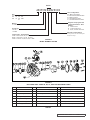
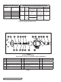
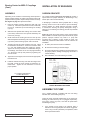
Series
AS 8 5 5 M B-MD2 B14 B
Drive Configurations
M = Motor, Face Mount
D = Direct Drive, Base Mounted
B = Bearing Carrier
R = Viking Reducer Drive
P = Commercial Reducer Drive
Size
(Nominal displacement)
GS
GG
HJ
HL
AS
AK
AL
KE
KKE
Magnetic Coupling Size and
Torque Specification - Drive
Related
A 4 and 9 Ft-Lbs
B 14,32 and 50 Ft-Lbs
C 40,90, 135 and 180 Ft-Lbs
Material
5 = Cast Iron
Port Design
M= DIN
U= ANSI
Magnetic Coupling Design
Coupling Size - Pump Related
A size = Used on GS, GG, HJ or HL
B size = Used on HJ, HL, AS, AK or AL
C Size = Used on AS, AK, AL, KE, or KKE
Second generation and not interchangable
with previous design.
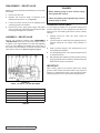
FIGURE 5
MODEL NUMBER SYSTEM
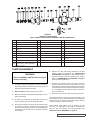
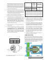
FIGURE 6
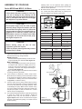
EXPLODED VIEW – SIZES AS, AK, AL, KE & KKE MAG DRIVE PUMPS
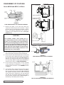
ITEM
ITEM
NAME OF PART
1
Locknut
NAME OF PART
ITEM
36
Rotor and Shaft Assembly
NAME OF PART
46
Capscrews (metric) for Relief Valve - 6 Req’d
21
Set Collar
37
Idler
47
Relief Valve
25
Casing Bushing
38
Idler Bushing
53
Locating Pin
30
Pipe Plug - 2 Req’d
39
Idler Pin
60
Thrust Washer - 2 Req’d
32
Casing and Bushing Assembly
40
Head and Idler Pin Assembly
61
Machine Screws (metric) - 2 Req’d
33
Casing Stem O-ring
43
Capscrews (metric) for Head - 6 Req’d
62
Drive Key
35
Head O-ring
45
Relief Valve Gaskets - 2 Req’d
63
Shims for Head (metal)
TABLE 2
SECTION TSM
685.2
ISSUE
F
PAGE 5 OF 16