1
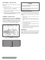
DISASSEMBLY / ASSEMBLY OF BEARING CARRIER
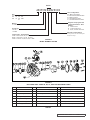
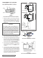
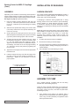
Bearing Carrier for MD2-B Couplings
Bearing Carrier
Housing
Retaining
End Cap and
Setscrew
Internal
Retaining Ring
Set Screw
Outer Magnet
Spacer
Ball Bearings
Bearing Carrier for MD2-C Couplings
“A”
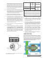
FIGURE 13
MD2-B OUTER MAGNET, BOLT ON HUB
AND BEARING CARRIER
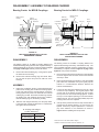
Set
Screw
Spacer
Tapered
Roller
Bearing,
(Outer)
Bolt-on
Hub
External
Retaining Rings
Lockwasher
and Locknut
Bearing Carrier
Housing
Outer
Magnet
Inner Key
Bolt-on
Hub
Tapered Roller
Bearing, (Inner)
Lipseal
“A”
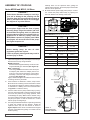
FIGURE 14
MD2-C OUTER MAGNET, BOLT ON HUB
AND BEARING CARRIER
DISASSEMBLY
DISASSEMBLY
The bearing carrier for an MD2 B coupling features two
sealed ball bearings along with the outer magnet assembly. If
further disassembly of this unit is required, reference Figure
7 on page 6 and Figure 13 then proceed as follows:
The bearing carrier for the MD2 C coupling features two
tapered roller bearings secured by a threaded end cap. The
unit is greased externally using the grease fitting. If further
disassembly is required, reference Figure 8 on page 7 and
Figure 14, then proceed as follows:
1. Remove the internal retaining ring. Using a press, press
the shaft out of the housing.
2. Remove the external retaining rings from shaft. Place
the unit into the press and push out shaft out of the
bearings.
ASSEMBLY
1. Place some Loctite® on the O.D. of the first bearing and
press into the housing bore. Position the bearing spacer
in the bore and insert the second bearing. Center the
bearing spacer then press in the shaft with one external
retaining ring on shaft. Press down until the ring contacts
the bearing race, then install the second ring. Install the
internal retaining ring into the bearing housing.
2. Slide the outer magnet assembly onto the pump shaft.
Locate the outer magnet per dimension “A” listed below
then tighten the two setscrews.
“B” Coupling Outer Magnet
Location Dimension*
Pump Design
“A” Dim.
U.S. Inch Design
8.49 inches
Metric Design
220.4 mm
1.Remove the two setscrews from the bolt-on hub and slide
the outer magnet off of the shaft. Remove the outboard
drive key in shaft.
2.Place the inboard side of the shaft in a vise with padded
jaws. Bend the lockwasher tab up and gently tap the
locknut in a counterclockwise direction. Remove the
locknut and lockwasher.
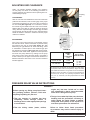
3. Loosen the two setscrews retaining the end cap. Back
out the end cap completely. Pull or gently tap the shaft
out the back of the bearing housing. Be sure to keep
the cup and cone of the outer bearing together. If either
the cup or cone requires replacing, it is recommended to
replace as a set. The inner cone will probably stay in the
housing unless it is to be replaced.
4. One lip seal is pressed into the end cap and the other is
pressed into the bearing housing. Do not remove the
lipseals unless they require replacement. If removed,
pay close attention to the orientation as shown in
Figure 14 when installing the new lip seals.
*Dimensions are not the same between designs
Loctite® is a trademark of Henkel Consumer Adhesives, Inc.
SECTION TSM
685.2
ISSUE
F
PAGE 9 OF 16