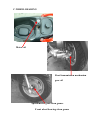
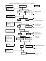
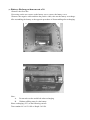
1
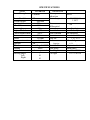
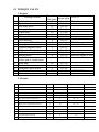
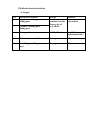
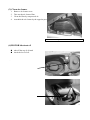
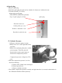
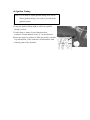
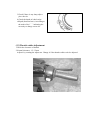
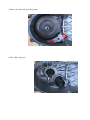
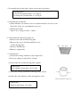
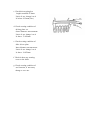
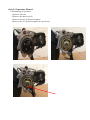
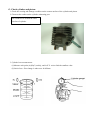
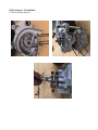
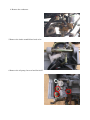
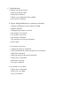
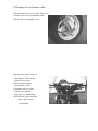
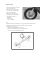
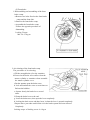
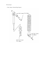
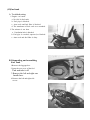
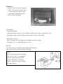
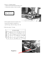
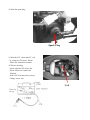
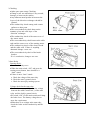
PREFACE
This manual offers all service specialists with the technological
procedures of maintenance, repairing for LIGERO-50 detailedly show
those whom may concern how to maintain, repair, change parts,
troubleshoot and reassemble, etc.
At every important section we illustrate by assembly, explosion
diagrams and photographs, if necessary, please check the diagrams
already shown.
Though we have tried our best, please kindly instruct us any
faults found in this manual.
MOTIVE POWER INDUSTRY CO., LTD.
CONTENTS
1. The specification
4
2. Service information
5
6
7
9
12
13
(1)The operation notice
(2)Looking torque value
(3)Lubrication instruction
(4)Wiring diagram
(5)Troubleshooting
3. Checking and adjustment
(1)Checking table
(2)Battery
(3)Clean the air cleaner
(4)Oil screen
(5)The final reduction mechanism oil
(6)Spark plug
(7)Compression pressure measurement
(8)Valve clearance
(9)Ignition timing
(10)Idle Adjustment
(11)Front brake adjustment
(12)Rear brake adjustment
(13)Tire
(14)Throttle cables adjustment
4. Dismantling, maintaining, repairing and assembling operation
(1)Lubrication system
(2)Plastic parts of chassis
(3)Engine dismantling
(4)Drive pulley, starter, clutch,driven pulley
(5)Cylinder head and valve
(6)Cylinder and piston
(7)AC generator flywheel
(8)Final transmission mechanism
(9)Crankcase, crank shaft
(10)Carburetor
(11)Steering stem, front wheel, front brake comp., front fork
(12)Rear wheel, rear brake, rear damper
(13)Fuel tank, oil tank
19
20
24
25
26
26
27
27
28
28
29
29
30
30
31
32
33
37
42
44
53
58
63
66
70
74
78
87
92
5. Electric equipment
(1)Troubleshooting
(2)Battery
(3)Recharge system
(4)Ignition system
(5)Starting system
(6)Starting clutch
(7)Handle bar switch
95
96
97
99
101
103
105
107
SPECIFICATIONS
Model
Overall Length
Overall width
Overall height
Seat height
Wheelbase
Dry weight
Engine Model
Piston displacement
Bore
Stroke
Compression ratio
Ignition
Clutch
Shifting
Lubricant
Steering angel
Left
Right
LIGERO-50
1780mm
645mm
1060mm
770mm
1210mm
99kgs
P2
49CC
40.0mm
39.2mm
6.8:1
Transmission
Primary
Direct
reduction
52/13*44/13
Secondary ratio
110CC
Reverse
differential
Frame
Front fork
Rear cushion
Front tire
Rear tire
Fuel
Capacity
CDI
Centrifugal / CVT Front brake
Drive
Auto seperated
、
41
41
Rear brake
Head light
Tail light
NA
Steel pipe
Telescopic
Uni-absorber
3.50-10*1
3.50-10*1
Unleaded gas
6.3L
Hydraulic disk brake
Durm brake
12V-35W*1
12V-21W/5W
Vehicle model reorganization:
1. Movable model
2. Fixed model
2. Service information:
(1)The notice for operation-------------------------------------------------------------------- 6
(2)Locking torque value----------------------------------------------------------------------- 7
a. For engine
b. For chassis
c. Others
(3)Lubrication instruction--------------------------------------------------------------------- 9
a. For engine
b. For chassis
c. Wheel bearing -------------------------------------------------------------------------12
(4)Wiring diagram----------------------------------------------------------------------------13
(5)Troubleshooting
1. Hard starting or no starting
2. Not smooth rotation(weak acceleration; inefficient horse)
3. Engine running not smoothly(low speed)
4. Engine running not smoothly(high speed)
5. Charging abnormal(battery over charging or over discharging)
6. No Sparking, spark plug
(1) The operation notice:
1. Always replace gasket, O ring, cotter, pins and clip whenever reassembled.
2. When tighten screws or nuts, lock tightly as per specified locking torque, and in the sequence of
cross direction.
3. Use PGO, or PGO Recommended parts.
4. After dismantling please wash all parts necessary for checking and grease all
contact surface when reassembling.
5. Use grease recommended by P.G.O.
6.When removing battery, please dismantle the negative pole (-) first, when
assembling please connect positive pole (+) first.
6. Before installing a new fuse, confirm the specification is correct or not.
7.After reassembling, please re-check that all connecting point, locking parts,
circuits, polar characteristics are good, before selling out.
(2) TORQUE VALUE
1. Engine:
No
1
2
3
4
5
6
7
8
9
10
11
12
13
14
15
16
17
18
19
20
Locking
Thread
Dia (mm) torque kg-m
Cylinder head
7
1.0~1.4
Flywheel outer
10
3.2~4.0
Rear brake lever
6
1.0~1.2
Driving pulley
10
3.2~4.0
Clutch outer
10
3.5~4.0
Right crankcase
6
1.0~1.2
Drive gear box cover
6
1.0~1.2
Left crankcase
6
1.0~1.2
Draining and filler bolt
8
1.8
Inlet pipe
6
1.0~1.2
Flywheel magneto stator
6
1.0~1.2
Cooling fan
6
1.0~1.2
Muffler nut on cylinder head
6
1.0~1.2
Starting motor
6
1.0~1.4
Bracket between eng. and
6
1.0~1.2
Rubber pad of central stand
Spark plug
14
2.5~3.0
Fan cover
6
1.0~1.2
Fixed plate, drive clutch
6
1.0~1.4
Nut of rear wheel axle
14
11~13
Kick starter
6
1.0~1.2
Locking location
Remarks
When the engine is cold
When the engine is cold
When the engine is cold
When the engine is cold
U TYPE NUT
2. Chassis:
NO
Locking location
Q’TY
Thread dia. (mm)
Locking torque (kg-m)
Remark
1 Locking nut, steering stem
1
10
4.5
2 Front axle nut
1
12
4.5 ~ 5.5
U type nut
3 Rear axle nut
1
16
11~ 13
U type nut
4 Rear shock absorber bolt(upper)
1
10
4.0
5 Rear shock absorber bolt(lower)
1
8
2.4 ~ 3.0
6 Front brake caliper bolt
2
8
2.0 ~ 3.0
7 Chassis bolt, engine hanger bracket
2
10
3.5 ~ 4.5
8 Engine bolt, engine hanger bracket
1
10
3.0 ~ 4.0
9 Brake hose bolt
2
10
3.0 ~ 3.5
10 Air release valve
1
6
0.6
11 Front drum brake arm bolt
1
6
1.0
12 Rear drum brake arm bolt
1
6
1.0
3.Other parts please refer the following table:
Standard torque values:
NO
1
2
3
4
5
6
7
8
9
10
11
Item
5mm bolt and nut
6mm bolt and nut
8mm bolt and nut
10mm bolt and nut
12mm bolt and nut
5mm screw
6mm screw
6mm flange bolt and screw
7mm flange bolt and screw
8mm flange bolt and screw
10mm flange bolt and screw
Torque (kgf- m)
0.45-0.6
0.8-1.2
1.8-2.5
3.4-4.0
5.0-6.0
0.35-0.5
0.7-1.1
1.0-1.4
1.0-1.4
2.0-3.0
3.0-4.0
(3)Lubrication instruction:
A. Engine
NO
1
Lubrication location
Crankcase: rotating part,
Sliding part
Oil type
Remarks
Auto-separated
Premium 2 stroke Lubrication
Motorcycle oil
Or SAE#30
2
Cylinder: rotating part,
Sliding part.
3
Drive gear box
SAE85-140
Total 110 c.c.
Replacement 90c.c
4
Gasket of starter shaft
Clean grease
(#3)
5
Start idle gear sliding
parts
Clean grease
(#3)
B.CHASSIS
Steel ball, steering
Front brake fluid
Front brake cam
C.WHEEL BEARING
Motor oil
Final transmission mechanism
gear oil
Speedometer gear-clean grease
Front wheel bearing-clean grease
(5)Trouble shooting:
1.Hard starting or can’t start:
Check and adjust
Trouble condition
The reason
loosen carburetor draining
screw, check if inside of
carburetor have fuel or not
•check there is fuel or not
The fuel supplies carburetor
No fuel supplies
enough or smooth
carburetor
‚pipe between fuel tank and
carburetor is blocked
ƒfloat is blocked
„Fuel gauze is blocked
…Auto cock is malfunctioned
Remove spark plug , insert
spark plug cover , and touch
•spark plug out of order
with engine check there is
‚dirty
any spark
ƒCDI unit out of order
„pulse generator out of order
…ignition coil cable disconnect
there is sparking in
No sparking or
spark plug
weak sparking
or short circuit
†Ignition coil disconnect or
short circuit
Measurement of
‡main switch out of order
compression pressure
ˆdefective magneto coil
•starting clutch out of order
pressure is normal
unsufficient or no
pressure
‚valve is too tight, no clearance
ƒvalve base out of orde r
„ Cylinder piston, piston ring out
out of order
start engine as the
…cylinder gasket leakage
instruction of starting
†valve burns out
engine
‡wrong valve timing
engine has no
engine knocking
•bad action of auto choke
knocking
and can’t start
‚air trapped in intake manifold
ƒwrong ignition timing
„bad adjustment of carburetor’s
Remove spark plug and
fuel adjusting screw
check again
dry
•carburetor fuel level too high
‚malfunction of auto choke
ƒthrottle valve open too largely
wet
2.Unsmooth rotation(Weak acceleration ; inefficient horsepower)
Check and Adjust
start engine and open
throttle gradually.
check and inspect
engine can rotate
up
The reason
Trouble condition
engine can’t rotate up completely
•air cleaner blocked
‚fuel supply system abnormal
ƒfuel tank cover blocked
„muffler blocked
…auto cock is malfunctioned
†auto chock is malfunctioned
Check ignition timing, check
with ignition timing lamp
•CDI unit is out of order
Timing is correct
Timing is
not correct.
bad adjustment
on valve
‚alternator flywheel magneto is
out of order
•Valve clearance adjustment is
Valve clearance is correct.
Valve clearance is incorrect
not correct.
‚Valve base is over worn out.
Check cylinder compression
pressure
(use cylinder compression pressure gauge.
Pressure is normal.
(Clearance valve is over extruded.)
Pressure is not normal
•cylinder, piston worn out.
‚cylinder gasket leakage.
ƒvalve base is malfunctioned
„wrong valve timing
Check carburetor
Is blocked or not
No blocked
blocked
No dirty and no
Color change
Dirty, color
change
clean the carburetor
Remove spark
Plug and check it
•clean the dirt.
Check the oil level in crankcase
Is too much or dirty
Oil level is
Normal.
‚specification is not correct.
•oil level is too high.
Oil level is
Not normal.
‚oil level is too low.
ƒoil does not interchange.
Check the lubrication
Of cylinder head
•oil route is blocked.
Normal
Abnormal
‚insufficient oil pumping from
oil pump.
Check engine overheat
Or not
Not overheat
overheat
Running accelerately or
High sp eed continuously
No knocking
knocking
•piston and cylinder worn out.
‚mixture is too lean.
ƒbad quality of the fuel.
„too much carbon in the combustion room.
…ignition timing is too early
•too much carbon in the combustion room.
‚bad quality of the fuel.
ƒclutch slip
„mixture is too lean.
…ignition timing is too early.
3. Engine running not smoothly(low speed and idling):
Check and adjust
Trouble condition
The reason
Check ignition timing
correct
Not correct
• CDI faulty
‚pulse generator faulty
Adjust carburetor oil screw
good
adjustment
faulty
adjustment
Check if there is air
Leakage on carburetor
gasket
No leakage
leakage
• mixture too rich
(loosen the screw)
‚ mixture too lean.
(tighten the screw)
•heat protector gasket
broke
‚carburetor locking nut
loose
ƒgasket crack
„hose ruptured
•spark plug is dirty
‚ CDI out of order
Good sparking
Sparking abnormal
Or no sparking
ƒAc magneto abnormal
„ignition coil faulty
…H.T. coil faulty or
short circuit
† main switch is abnormal.
Check A.C.V
•A.C.V. faulty
good
fault
‚hose is damaged.
ƒair pipe is blocked or
damaged
4.Engine running unsmoothly(high speed)
Check and adjust
Trouble condition
The reason
Check ignition
timing
•CDI sets faulty
correct
not correct
‚pulse generator faulty
Adjust valve gap
correct
Not correct
•bad adjustment
‚valve base faulty
Check auto cock,
Fuel supply system
good
unsmoothly
•fuel level is too low
‚fuel pipe or fuel filter
is blocked
ƒauto cock faulty
Check carburetor
Is blocked or not
No blocked
blocked
clean and wash it
Check valve timing
correct
Not correct
the mark of cam’s timing
gear does not align
Check the valve’s
Reverse spring
good
Spring broke or fatigue
Spring faulty
5.Charging abnormal(battery over charing, or over discharging)
Check and adjust
Trouble condition
The reason
Measure batter’s
Voltage then start
engine
Voltage re main
The Same
Voltage goes up
To normal value,
But after engine
Stop ,the Voltage
Goes down again
•Battery is dead
‚Battery malfunction
Check voltage rectifier
Plug is loose or not
•poor connection
good
loose
‚red cable disconncet
Check the voltage
Between chassis Θand
The red cable♁ of
Voltage rectifier
No voltage
good
•voltage rectifier
malfunction
‚while cable disconnect
Check the resistivity
Of A .C . generator coil
normal
abnormal
charging abnormal(over charging)
Start engine, connect
Green cable to
Chassis, then measure
The voltage between
Chassis Θand red cable
♁of voltage of
rectifier.
Voltage higher
Than specification
•defective coil
‚poor connection
ƒA.C. generator’s
white cable
disconnect
Voltage normal
Check the connection
Of the cable of
Voltage rectifier
•cable poor connection
good
Poor connection
‚poor connection of
green cable
Check the resistivity
Of the body of
Voltage rectifier
Out of spec
Voltage rectifier
faulty
6.No sparking, spark plug
Check and adjust
Trouble condition
The reason
Replace new spark
Plug, then check
again
Weak sparking
Or no sparking
Good sparking
spark plug faulty
Check spark plug, cap
And H.V. cable is
Loosen or not
good
loose
spark plug cap loosen
Check the CDI plug
Is loosen or not
good
Check the connection
Between CDI Plug and
Each terminals, check
The resistivity of
Each terminals
loose
good
abnormal
plug is poor
connection
•main switch faulty
‚defective magneto
coil
ƒpulse generator faulty
„defective ignition
coil
Check relative parts
good
good
abnormal
Check ignition coil
By the CDI tester
abnormal
abnormal
•main cable broke
‚poor connection of
joints or sockets
defective CDI
defective ignition
coil
3.Checking and Adjustment:
(1)Periodical checking table
(2)Battery
(3)Clean air cleaner
(4)Oil screen
(5)The final reduction mechanism oil
(6)Spark plug
(7)Cylinder pressure
(8)Valve clearance
(9)Ignition timing
(10)Idle adjustment
(11)Front brake adjustment
(12)Rear brake adjustment
(13)Tire
(14)Throttle cable adjustment
(1) Periodical checking table:
1.[○] mark indicates periodical checking
2.[*] indicates changing the parts
Check item
A Suspension Loose,swing
Steering
Handlebar performance
Suspension: turning angle
a.cracked
b.shaft fixed
Front fork
condition
c.shaft:loose
B: Brake
a.clearance
General
checking
First
Month
Or
Initial
500km
Checking period
Home
Office
Per 6
per12
Per1
per3
Months months
Months months
Or
or
Or
or
5000km 1000km 1000km 2500km
Judgement
per12
Remark
standard
months
or
10000km
○
○
○
○
○
○
○
○
○
○
○
○
○
○
○
○
○
○
○
○
○
○
○
○
○
○
From steering
column
○
Clearance:
○
○
○
○
○
○
Front:10-20mm
Check from
Steering
column
Rear : 10-20mm
Brake lever b.movement
of
brake
○
Loose or damage
brake
Brake cam
○
○
○
○
○
○
○
○
○
○
○
○
Brake cables
change
Worn out
※per 2 years
○
a.clearance between
drum and plate
b.brake shoe and br
ake plate worn out
○
Brake drum
And brake
c.brake drum
shoe
worn and
damage
○
○
○
○
○
○
○
○
○
front axle:damage or cracked
rear axle:worn
or damage
Wheel pressure
wheel
Wheel cracked
Or damage
Wheel gap and
worn
Wheel surface
Or other metals
Axle nut screw
Pin tightness
Wheel rim swiNgness and daMage condition
Standard dia:
Rear:130.0mm
Limit of use:
Rear:131mm
mark type
○
Check rear
Axle
○
○
○
○
○
○
○
○
○
○
○
○
○
○
○
○
○
○
○
○
○
○
○
○
○
○
○
○
○
○
○
○
○
○
Unit:kg/c ㎡:ldriver U
1.5
1.75
Gaplimit:front wheel:
0.8mm rear wheel:0.8mm
○
Front axle
screw torque
5.0-6.0kg-m
rear axl e torque
11..0 -13.0kg-m
○
Swingness ofr
front
Rear wheel rim.
Vertical
swing:2mmbelow
Horizpmta;”:2mm
b;epw
Nut
location
Check item
Wheel
Front
Bearing of axle,
Looseness
Rear
Damper Rear damper spring
cracked
ass’ part loose
or damage
Connecting part
Loose
Bracket loose or
Damage
SuspenConnecting
sion
Part loose
Oil leakage
Cracked
damper
assy's part,
Loose
Clutch and
Change
Power Speed
Transmi- mechanism
Ssion
General
checking
Supply
grease
Electric
InstallMent Ignition
Start
mechanis
m
wiring
battery
wire
circuit
First
Month
Or
Initial
500km
○
Checking period
Home
Office
Per6
per12
Per1
per3
Months months
Months months
Or
or
Or
or
5000km 1000km 1000km 2500km
○
Wire connecting
Loose or
cracked
○
○
○
○
○
○
○
○
○
○
○
○
○
○
○
○
○
○
○
○
○
○
○
○
○
○
○
○
○
○
○
○
○
○
○
○
○
○
○
○
○
○
○
○
○
○
○
Starting
Motorpinion
Meshing
Recharge
Effect
ElectrolyTe quantit
ElectrolyTe s. gravity
○
Judgement
per12
Remark
standard
months
or
10000km
○
○
○
○
○
○
○
※per 2 year
Clearance:
0.6~0.7mm
NGK:BP7HS
A
OR SAME
SPEC
○
○
○
○
○
○
○
○
○
○
Level between
“UPPER” AND
“LOWER”
○
○
WHEN 20℃
SPECIFIC
GRAVITY:
1.270-1.290
○
○
○
○
○
○
Check item
General
checking
First
Month
Or
Initial
500km
Engine Engine Performance,
parts
noise
Low speed,
Accleration
Exhaustion
○
Air cleaner
Checking period
Home
Office
Per6
per12
Per1
per3
Months months
Months months
Or
or
Or
or
5000km 1000km 1000km 2500km
Judgement
per12
Remark
standard
months
or
10000km
○
○
○
○
○
○
○
○
○
○
○
○
○
○
○
○
○
○
○
○
Cylinder, cylinder head inlet
Pipe, locking
Condition
○
Compression
pressure
○
○
Idling:1900±
100rpm
Check the clolr
Or exhausting
-air
Locking torque
Cylinder head:
(cold)
1.0-1.2kg/m
Using stating
Motor.
6.0kg/c ㎡
(750rpm)
Oil leakage
○
○
○
○
○
LubricatIon
System
Oil quantity,
Dirty
Oil quantity,
○
○
○
○
○
Add if
necessary
○
○
○
○
Change every
5000km
fuel
system
Fuel quantity
Fuel leakage
○
○
○
○
○
Carburetor
Parts dirty
Carburetor throttle and choke
Performance
○
○
○
○
○
○
○
○
○
○
Carburetor
Float height
○
○
○
○
○
Carburetor
Adjustment
○
○
○
○
○
○
Oil filter
Fuel pipe
Changing
○
○
※per 4 years
General
checking
Check item
Lamp system
Performance
Dirty, cracked
Horn turn
Signal
Reflector
lock
Rear view
mirror
Performance
First
Month
Or
Initial
500km
Checking period
Home
Office
Per6
per12
Per1
per3
Months months
Months months
Or
or
Or
or
5000km 1000km 1000km 2500km
Judgement
per12
standard
months
or
10000km
○
○
○
○
○
○
○
○
○
○
○
○
○
Performance
○
○
○
○
○
○
○
○
○
○
○
○
○
○
○
○
○
○
○
○
○
○
○
○
○
○
○
○
○
○
○
○
○
Check the
illumination
Blinker linc-
Dirty
Nese plate nu-
cracked
○
○
Mber&mark
Instrument
performance
○
board
Ass’y part
Muffler
silencer
Loose
cracked
performance
loose or
chassis
cracked
The earlier
Abnormal
Confirm it does
Not happen
○
again
condition
Chassis
○
○
○
Lubrication
others
Decoking mixer
,muffler,
silencer
○
○
Remark
Horn
Turn signal
(2)
Battery: Recharge when run out of it
1.Remove the floor mat.
2.Screwing out the two screws on the battery cover; remove the battery cover.
3.Remove the negative cable and then the positive cable, take out the battery to recharge.
4.Re-assembling the battery as the opposite procedure of disassembling after recharging.
Note:
A.
Do not take out the sealed bolt when recharging.
B.
Without refilling water fo r the battery.
Please recharging (12V) as the following current.
Time standard: 0.3A*5~10Hr or Rapid: 3A*1Hr
(3) Clean air cleaner
1.
2.
3.
4.
Remove air cleaner cover.
Take out the air cleaner filter.
Clean the filter by compressed air.
Assemble the air cleaner by the opposite procedure.
Attn: Do not start engine when air cleaner is not installed.
(4)MOTOR lubricant oil
n
n
.
take off the cap of oil tank
check the level of oil.
(5) The final reducing mechanism
oil
1.Change the oil in the gear box:
a. Turn off the engine after warm up.
b. Put a bowl under the engine.
c. Remove the draining bolt and filling
bolt to drain the gear oil off.
d. Lock the draining bolt before refill
110c.c. gear oil and then lock the filling
bolt.
e. Locking torque:1.8kg.m
Draining bolt
Filling Bolt
(6)Spark plug
1.Remove spark plug.
2.Check the spark plug electrode and see whether it is burnt out/ carbonized or not.
3.Clean the electrode, if it is dirty.
lSpark plug specification
NGK: BP7HS or BPR7HS equivalent
Gap of spark plug:0.6~0.7mm
spark plug
Electrode burnt out
Carbon piled up or not
Washer is distorted or not
Porcelain is cracked or not
(7) Cylinder Pressure
1.Measure it when the engine is warm.
2.Remove the cover at the right hand of the
step floor.
3.Remove the spark plug then place cylinder
pressure gauge. Then fully open the
throttle and act on the starter motor to
measure the compression pressure.
Compression pressure: 6.0kg/cm2 at 750
rpm
*When the compression pressure is too low,
check the following:
a. Gasket of the cylinder head is damaged.
b. Piston ring worn-out
c. Piston or cylinder worn-out
*The cylinder compression pressure is usually too high when there is too much carbonization in
the combustion chamber and the piston tip.
(8) Ignition Timing
Note: It is no need to adjust ignition timing and CDI set.
When ignition timing is not correct, just check the
ignition system.
1.Remove the checking hole cover of ignition timing.
2.Using the ignition timing light to assure the ignition
timing is correct.
3.Under idling, it means in good function when
crankcase’s mark matches to the “F” on the flywheel.
4.Raise the engine revolution to 5000 rpm slowly, it means
in good function, if the crankcase's mark matches with
Entering point of the flywheel.
(9) Idling Adjustment
Note: Adjust idling only when the engine is warm.
1.Remove the checking hole cover of carburetor.
2.Start the engine and connect the tachometer.
3.Adjust the throttle valve screw to the
specified revolution.
4.Specified idling revolution: 1900 ± 100rpm
lIf rpm is still unsteady or fuel up is not
smooth, please re-adjust the fuel intake
screw.
(10) Front Brake Adjustment
1.Check the clearance of front brake lever
Clearance: 10-20mm.
2.If the clearance is beyond standard, check whether:
a. The air mix into the pipe/caliper.
b. The oil brake system is leaking.
Note: Try brake le ver to see if it’s loose. Check the
brake oil.once air mixed in the oil pipe, which
will reduce or damage the brake efficiency or
even its function.
3.Check the oil level:
a. Refill the brake oil when the level is under the LOWER line.
b. Oil specification: SAE J-1703 or DOT3 orDOT4.
Note:
a. To prevent the oil splitting onto the parts or clothes, put a piece of cloth on the bottom when
refilling.
b. Be caution not to mix water or particles into the master cylinder when refilling.
c. Never use the oil that is not complied with spec.
d. In case the oil stains on the eyes, wash with water at once and then ask for medical care
immediately.
(11) Rear Brake Adjustment
1.Check the clearance of rear brake lever.
Clearance: 10~20mm
2.If the clearance is beyond the above
Standard, adjust it by rotation the screw.
a. Left-handed rotation-Enlarge the clearance.
b. Right-handed rotation-Reduce the clearance.
Note: When the arrow of rear brake indicator align with the arrow of left crankcase, cha nge
the brake lining.
(12) Tire:
1.Check Tire air pressure.
2.Tire pressure:
Front tire: 1.50kg/cm2
Rear tire:1.75kg/cm2
3.Tire specification:
Front tire: 3.5-10
Rear tire: 3.5-10
Note:
1.Check and adjust the tire pressure when it is too low.
The pressure is according to the carrier, driver, passenger, accessories and cruise speed
2.Proper loading is very important for steering, riding, braking, performance and safety.
Never carry any parcel unfastened.
Load the heaviest parcel on the center of vehicle, balancing the weight on both sides.
Beware of the weight loaded properly and check the tire pressure. The total weight of
carrier, driver, passenger, and accessories cannot exceed the approved limit. An overload
vehicle is easy to cause tire damage and accident for rider
3.Check if there is any sharp object
piece the tire.
4.Check the depth of wheel stripe.
lDepth (front and rear): According to
the mark of tire” ” indicating the
necessity to change a new tire.
(13) Throttle cables Adjustment
1.Check the clearance of throttle
2.Normal clearance: 1.5-3.5mm
Adjust it by rotating the adjust nut. Change it if the throttle cables can’t be adjusted.
4. Dismantling, Maintaining, Repairing and assembling operation
(1)
(2)
(3)
(4)
(5)
(6)
(7)
(8)
(9)
(10)
(11)
(12)
(13)
Lubrication system
Plastic parts of Chassis
Engine dismantling
Drive pulley, starter, clutch, driven pulley
Cylinder head and valve
Cylinder and piston
AC generator
Final transmission mechanism
Crankcase, crank shaft
Carburetor
Steering stem, front wheel, frt brake comp., frt fork
Rear wheel, rear brake, rear damper
Fuel tank
(3)Engine Dismantling
A. Dismantling engine.
1.Take off the luggage compartment.
2.Take off the left and right body covers.
3.Take off the lower mudguard fender.
4.Remove vacuum pipe, fuel pipe, auto choke, cap of spark plug, rear
Brake cable carburetor pipe, engine flywheel shelf’s nut, starter
Motor cable plate and rear damper bolt.
5.Remove the engine.
B. Installing Engine.
1.To install engine, please reverse the above procedures.
2.Locking torque:
M8: 2.0~3.0kg- m
M10: 3.0~4.0kg- m
M12: 5.0~6.0kg- m
3.After installing, please do the following checking and adjustment:
Checking and adjustment:
a. Wiring connection.
b. Throttle cable and oil control cable.
c. Rear brake adjustment.
d. Fuel and oil route.
(4)Drive pulley, starter & clutch
A. Troubleshooting:
a. Engine starts, but vehicle does not move.
1.driving belt worn out
2.driven plate worn out
3.clutch lining worn out
4.driving plate’s spring broken
b. The vehicle stops or trembles when running,
1.clutch lining spring cracked or broken.
c. Can’t reach high speed, no pick-up
1.driving belt worn out.
2.Driving plate spring distortion.
3.Weight roller worn out.
4.Driving plate abnormal.
Note:
No grease and oil allowed to stain on driving belt and driven plate.
B. CVT parts measurement data
Item
Model
The inner dia. of
Slide driving plate
The outer dia..of boss, movable
Driving plate
Belt width
Clutch lining thickness
Clutch outer diameter
Driving plate spring, free length
The outer diameter of driven
plate sets
The inner diameter of slide
Driven plate
The outer diameter of weight
Roller set
Standard value(mm)
50cc
Limit of use(mm)
50cc
20.035-20.085
20.123
19.960-19.974
19.911
18.0-19.0
3
117.0~117.2
87.9
17.0
1.5
117.5
82.5
33.965~34.025
33.95
34.000~34.025
34.070
15.992~16.008
15.50
C. Driving pulley.
1.Take off the 8 screws of left
Cover, remove the left cover.
2.Take off the left cover.
3.Remove the fixing nut of the clutch.
4.Take off the ramp plate.
5.Take off the belt and the rear clutch.
6.Take off the driving plate.
• Take off the driving gear start set.
7.Remove the start idle gear fixing plate.
8.Take off the idle gear.
9.To assemble the driving pulley, please reverse above procedure.
Locking torque:
1.Nut of driving pulley:M10: 3.2~4.0kg- m
2.Locking nut of clutch:M10: 3.5~4.0kg- m
10.Checking the driving belt
(1)check whether it is cracked or not or its rubber and fiber are loose or not
check also if they are extraordinarily worn out.
(2)driving belt width:
limit of use : change it below 17.0mm.
11. Disassemble the slide driving plate set
(1)Remove the bush of slide driving plate
(2)Remove the screw, and disassemble the cover
of slide driving plate.
(3)Remove RAMP plate.
(4)Remove weight roller.
12.Checking list:
(1)Check the wearing condition of the weight roller.
limit of use: change it when below 15.5mm.
(2)Check inner dia of slide driving plate’s gasket.
Limit of use:
50cc:Change it when above 20.123 mm
(3)Check the wearing condition for driving pulley surface.
(4)Check the outer diameter of the driving plate’s boss.
Limit of use:
change it when below 19.911mm
13.Assemble the slide driving plate.
(1)Clean the inner surface of slide driving plate, then assemble the roller.
(2)Assemble the ramp plate.
(3)Please reverse the procedures of disassembling to finish assembling.
D. Starter dismantling
1.Dismantle the left crankcase cover
2.Remove the hexagon nut, then remove the starter lever.
3.Remove five screws of isolating plate.
4.Remove the starter spring from the start returning positioner.
5.Remove the driven gear comp of kick starter.
6.Remove the retaining c-type clip
7.Remove the spindle comp.
Of kick starter.
8.Checking the starter
a. Check the wearing condition of the outer diameter of the spindle comp
and the inner diameter of bush and gear.
b. Check the wearing condition of the shaft of driven gear comp, gear
sets and ratchet.
9.Assembling the starter
To assemble the starter, please follow the opposite procedures of dismantling.
Locking torque: M6:1.0~1.2kg- m
Note:
•Make sure that on end of the torsion spring is hooked on the groove of
driven gear, and another end of the torsion spring is hooked on the poled
inside the left crankcase.
‚Put some grease on shaft and gear sets before assembling.
E. Clutch driven pulley
1.Dismantle the clutch
a. Remove left crankcase cover.
b. Remove driving plate.
c. Remove driving belt.
d. Remove the M10 locking nut, then the clutch.
2.Assembling the clutch: please follow the opposite procedure of dismantling.
Locking torque:
M10: 3.5~4.0kg- m
3.Checking the clutch:
Dismantling the clutch needs the special
Tool. please contact your dealers.
a. Check the clutch driven face.
Check the clutch cover about its wearing
Condition and inner diameter measurement.
Limit of use:
50cc:Change it when above 117.5mm
b. Check the clutch lining wearing condition
and measure the lining thickness
limit of use: change it below 2.5mm.
c. Check driven spring free
length: standard: 87.9mm
Limit of use: change it as it
Is below 82.5mm(50cc)
d. Check wearing condition of
driving plate set.
Outer diameter measurement:
Limit of use: change it as it
Is above 33.950mm
e. Check wearing condition of
slide driven plate.
Inner diameter measurement:
Limit of use: change it as it
Is above 34.070mm
f. Check is there any wearing
occur to the ditch.
g. Check wearing condition of
seal location, if necessary
change a new one.
(5)Cylinder and piston:
A. Troubleshooting.
a. compression pressure is too low, difficult to start engine and running unsmoothly.
1. Cylinder head gasket cracked.
2. Spark plug is not well- locked.
3. Piston ring worn out or cracked.
4. Cylinder, piston worn out.
5. Reed valve is defective.
b. compression pressure is too high, engine overheating or abnormal noise.
1.piston tip has too much carbon piled up.
c. Abnormal piston noise
1. cylinder and piston worn out.
2. Piston pin hole or piston pin worn out.
3. Connecting rod small-end or bearing worn out.
d. Abnormal piston or cylinder noise
1.piston ring worn out or cracked.
2.Cylinder worn out or cracked.
B. The operation notice:
1.clean before operation to avoid particles dropping into engine.
2.The connect surface of gasket must be clean.
3.Dismantle the cylinder and the cylinder head by screw driver.
Do not scratch the contact surface.
4.Cylinder inner surface and piston outer surface can’t be scratched.
The contact surface should be lubricated by specified oil.
C. PISTON & CYLINDER DATAS:
Standard Value
(mm)
Part name/description
Cylinder head
cylinder
Piston/
Piston ring
Flatness
Bore
Clearance b/w Piston
ring piston and
Lst ring
2nd ring
Piston outer diameter
Measuring location of piston outer dia.
(12mm from the lower end of skirt)
Clearance b/w piston and cylinder
Piston pin hole inner dia
Piston pin hole inner diameter
Piston pin outer diamerer
Clearance between piston and piston pin
Connecting rod small end inner dia
39.995~40.015
Limit of use
(mm)
0.100
40.050
0.05~0.06
0.10
0.05~0.06
39.950~39.970
0.10
39.895
0.045~0.065
13.022~13.013
10.002~10.008
9.994~10.000
0.004~0.018
13.996~14.007
0.10
13.045
10.025
9.970
0.030
14.025
D. cylinder head, cylinder, and piston dismantling.
1.Remove the engine.
2.Screwing out the two M6-bolt of cooling cowl.
3.Screwing out the two M6-blot of fan cover.
4.Remove the cooling cowl and fan cover.
5.Remove the spark plug.
6.Remove the two M6 nuts on the muffler and cylinder.
Also remove the two M8-bolt of crankcase.
7.Remove muffler.
8.Remove the four M7-nut on the cylinder head, then remove the cylinder head
and cylinder head gasket.
9.Remove the Cylinder and the gasket.
10.Remove the c type clip on the piston and piston pins by the nipper.
•Take off piston.
11.Dismatling of the piston ring Take off the first piston ring then the second ring.
12.When assembling please reverse the procedures of dismantling.
Locking torque:
M7:1.0-1.4kg- m
M6:1.0-1.2kg- m
Opening end of piston ring
(6)A.C. Generator, Flyweel
A.Dismantling AC generator
1.Remove fan cowl.
2.Remove the M6 screws(4)
3.Remove Screws of flywheel magneto
4.Remove the AC flywheel magneto by special tool.
5.Remove the flywheel.
6.Remove the electric plug of AC Flywheel magneto.
Take out the magneto.
B. Install AC generator
To install, please reverse the dismantling procedures.
Locking torgue :
M6: 1.0~1.2kg- m
M10: 3.2~4.0kg- m
(7)Final Transmission Mechanism
A. Trouble shooting
lEngine can be started, but vehicle doesn’t move.
1.Gear worn-out or cracked.
2.Gear burnt out.
lNoise occurs when running.
1.Gear worn out, burnt or gear surface damaged.
2.Bearing worn out or loosen.
lOil leakage
1.Too much oil.
2.Seal worn out or damaged.
B. Disassemble the final transmission mechanism.
1.Remove the rear wheel.
2.Drain off the oil in the gear box.
3.Remove the 6 bolt in gear box cover
4.Take off the gear box.
5.Take out the final reduction gear and idle gear shaft.
6.Clean up the gear box
C. Check the final transmission mechanism
1.Check the wearing condition of the driving shaft and
gears.
2.Check the wearing condition of the idle gear shaft and
idle gears.
3.Check the wearing condition of the final reduction gear.
4.Check the wearing condition of the oil seal and bearing.
D. Assemble the final transmission mechanism:please follow the opposite procedures
Of disassembling. After locking the drain bolt, refill 90c.c of gear oil, SAE 85W/140.
Locking torque: M6: 1.0~1.2 kg- m
M10: 3.5~4.0 kg- m
Drain bolt:
M8: 1.8 kg-m
E. Check for the flatness of cylinder head & cylinder.
Check the flatness of contact surface of cylinder head & cylinder.
Limit of use: If it exceeds 0.1mm
Change a new one.
F. Combustion chamber cleaning
lClean out the carbon piled up in combustion chamber.
lDo not scratch the combustion chamber and contact surface of the cylinder during
cleaning operation
G. Check cylinder and piston:
1.Check the wearing and damage condition on the contact surface of the cylinder and piston.
2.Clean out the carbon on the cylinder exhausting port.
Be careful not to scratch the inner
Surface of cylinder.
3.Cylinder bore measurement:
(1)Measure each point (A)(B)(C) orderly, and in X.Y. axis to find the smallest value.
(2)Limit of use: 50cc-change it when over 40.050mm
4.Piston outer diameter measurement:
(1)Measure at the skirt area where is 12 mm from the skirt lower end of skirt.
(2)Limit of use: 50cc-change if when below
39.895mm
(3)Calculate the clearance between the cylinder and piston.
Limit of use: change it when over 0.100mm
5.Inner diameter measurement of the piston pin hole
Limit of use: change it when over 14.032mm
6.Outer diameter measurement of the piston pin
limit of use: change it when under 9.970mm(50cc ENGINE)
7.Check piston ring:
Measure piston ring gap:
Limit of use: change new ones when the first ring and second ring are over 0.4mm
Push the piston ring into the cylinder
By piston, the measure the gap
8.Check connecting rod small end
(1)lnstall piston pin, bearing onto the connecting
rod small end, then check the looseness
of the piston pin.
(2)Measure the inner diameter of the connecting
rod small end.
Limit of use: replace a new one when over 14.025mm.(50cc ENGINE)
H. Installing cylinder and piston
1.Place the piston ring into the second ring ditch first, then install the
piston ring into the first ditch.
2
a. Piston ring should be installed into piston ring ditch by even force
b. After assembling, be sure that the piston ring sliding surface is at the same height as
the piston outer surface.
c. If the piston ring can not fit into the ditch, please clean up the carbon in the piston ring
ditch or piston ring itself.
3.
a. Piston ring must be installed in the correct location.
b. After installing the piston ring, it should be able to rotate freely.
c. If it is necessary to change the new piston ring, it must change the whole set.
4.
a. The location of the piston ring gap and the lock pin must be in opposite side.
b. The mark”à” on the piston tip must be pointing to the exhaus ting port.
c. Lubricate the piston pin before installation.
5.Please follow the opposite procedure of dismantling to install cylinder and cylinder head.
(8)Crankcase, Crankshaft:
A. Disassembling diagram
B. Troubleshooting.
Engine noise:
1.The bearing of final transmission mechanism is loose.
2.Crank pin bearing is loose.
3.The bearing of gear box is loose.
C. Data
Measuring Item
Clearance of connecting rod big end
(Parallel direction to rod)
Clearance of connecting rod big end
(Perpendicular direction to rod)
Swingness of the crank shaft neck
Standard value
Limit of use.(mm)
0.20-0.50
0.71(50cc)
-
0.04
0.03
0.10
D. Dismantle the crankcase and crankshaft please follow the following procedures:
1.Remove the engine.
2.Remove the left crank case, the driving pulley (driving plate) clutch and belt.
3.Remove the air cleaner.
4.Remove the carburetor.
5.Remove the intake manifold and reed valve.
6.Remove the oil pump, fan cowl and fan itself.
7.Remove the AC flywheel magneto.
8.Dismantle the right and left crankcase.
There are all together 7 bolts.
9.Remove center stand, left and right crankcase and take out the crankshaft.
E. Check the crankshaft:
1.measure the clearance between crank
shaft and co-rod big end.(Parallel
direction to rod)
Limit of use: Replace a new when above 0.71mm
2.check the looseness on X.Y. axis of the connecting rod big end(Perpendicular directions to rod)
Limit of use: Replace a new one when above 0.04mm
3.measure the swingness of crank shaft neck.
Limit of use
A
B
Change it when
Change it when
Above 0.1mm
Above 0.1mm
A
B
60mm
4.check the slackness of crankshaft bearing,
if it is slack, change a new one.
F. Assemble the crankcase.
1.To assemble the crankcase, please reverse the procedures of disaseembling.
2.The locking torque value for bolts and nuts are all described in the previous chapters
Please refer.
(9)Carburetor, Reed Valve and Auto cock
A. Fuel system diagram
Fuel Cap
Fuel Gauge
Fuel Tank
Carburetor
B: Carburetor dismantling diagram
01
02
03
04
05
06
07
08
09
10
11
12
CARBURETOR ASSY.
TOP SET
SPG., COMP.
PLATE SET
TUBE SET
JET NEEDLE
THROTTLE VALVE
SCREW SET
SCREW SET(A.S)
O RING
NEEDLE JET
SLOW JET
13
14
15
16
17
18
19
20
21
22
23
24
HOLDER, NEEDLE JET
MAIN JET
FLOAT VALVE SET
PIN, ARM
FLOAT SET
FLOAT CHAMBER SET
TUBE SET
"SCREW, WASHER"
CAP HOLDER
AUTO BYSTARTER SET
SCREW, WASHER
PLATE SET
C. Troubleshooting:
a. Engine can not be started.
1.No fuel in the fuel tank.
2.Fuel pipe is blocked.
3.There is too much fuel in the cylinder.
4.Air cleaner is blocked.
b. Engine idling(RPM)unsteady, running not smoothly
1.Improper adjustment of the carburetor idling.
2.Ignition disorder.
3.Compression pressure is too low.
4.Air mixture is too thick.
5.Air mixture is too lean.
6.Air cleaner is blocked.
7.Air injection is not in good function.
8.Fuel is dirty.
c. Air mixture is too lean.
1.Carburetor main jet is blocked
2.The ventilation hole of the fuel tank cover is blocked.
3.Fuel filter is blocked.
4.Fuel pipe bended, squeezed or blocked.
5.Float valve is abnormal.
6.Fuel level is too low.
7.Air pipe is blocked.
d. Air mixture is too thick
1.Float valve is abnormal.
2.Fuel level is too high.
3.Air jet is blocked.
D. Dismantling carburetor
1.Remove the luggage box.
2.Loose the hose clamp between the carburetor
and the air cleaner.
Then remove the air cleaner.
3.Unscrew the fuel draining screw of the
carburetor. Drain off the fuel inside the
carburetor.
4.Remove the fuel pipe and the vacuum pipe on
the carburetor.
5.Remove the oil pile on the carburetor.
6.Remove the bolts on the intake manifold and
carburetor.
E. Dismantling float, nozzle
Note:
The auto choke has been properly adjusted already. Please do not adjust it further.
When there is blockage in the carburetor, please clean it by air compressor.
F. Reed valve
1.Dismantling reed valve.
(1)Take off the luggage box
(2)Remove the air cleaner
(3)Remove the carburetor.
(4)Unscrew the locking screw of the intake
manifold.
(5)Remove the intake manifold.
(6)Remove the reed valve.
2.checking for the reed valve.
§chang a new one when the reed valve is worn out or distorted.
§change a new one too when the base of the reed valve is cracked, injured or distorted.
G. Check the auto cock
1.When the engine stop, remove the fuel pipe from carburetor and check if there is fuel flow
Out or not.
It means auto lock functions well if the residue fuel(for the amount of 5-10cc)flows out
From the auto cock and fuel pipe. However, if it continues to flow out, it means that the
Vacuum pipe is blocked. please clean it.
2.Remove the vacuum pipe from the carburetor and suck it to produce a vacuum to have the
Fuel flow out from the fuel pipe. The fuel will stop flowing out if the vacuum disappear.
If the fuel does not flow out by the above operation, please check the followings:
(a) Clean out blockage in the vacuum pipe.
(b)Blow air into the inlet pipe of the auto cock.
3.Note:
Please remember to use a bowl to catch the flow-out at the end of the fuel pipe.
Keep away from fire or even spark during operation.
(11)Steering stem, front wheel, frt brake comp and front fork.
A. Troubleshooting
B. Data
C. Steering handlebar
E. Front wheel
F. Front brake
G. Front fork
A.Troubleshooting
1.steering handlebar is abnormal, too tight.
a. steering mechanism; washer of conical bush locked too tightly.
b. steering mechanism; steel ball is cracked.
c. steering mechanism; steel ball base and washer of conical base is damaged.
d. wheel pressure is too low.
2.steering handlebar is aslant.
a. left and right damper is not even.
b.Front fork is crooked.
c. The axle of front fork is crooked, wheel is aslant.
3.front wheel swings.
a.wheel rim is distorted.
b.bearing of front axle too free.
c.wheel rib is distorted.
d.Wheel is not good.
e. Front wheel axle locked improperly.
4.front damper is too soft, spring fatigue.
5.noise in front damper.
a.noise comes from damper box.
b.locking screw of damper is slackness.
B.Data
Item
Standard value ( mm )
Limit of use ( mm )
Lining of frt brake
4.0
2.0
Disk of frt brake
3.6
3.1
-
2.0
Swingness of frt/rr wheel
C.Changing the speedometer cable
1.Remove the fixed screws of the front cover.
2.Remove the nut of speedometer cable.
3.Remove the front handle cover.
4.Remove the fixed screws of
speedometer cable on the
right of front wheel.
5.Draw out the damage
speedometer cable.
6.Assemble the new cable
follows the opposite
procedure of dismantling.
NOTE:Put the grease onto the
Inner cable before
Assembling.
(D)Steering handlebar
1.Remove the LH/RH back mirrors.
2.Remove the upper handle cover.
3.Remove the nuts on front fork and handlebar.
4.Take off the fixing bolt.
5.Remove the nut and bolt of the front
fork fixed on
The handlebar.
6.Take off the handle bar.
7.When assembling, please follow the opposite procedures.
Locking Torque:
M6
:1.0-1.2kg- m
M10 :3.0-4.0kg- m
8.Before assembling, please add grease on each cable.
(E)Front wheel
1.Remove the locking nut of the front
wheel on the right side.
2.Draw out the axle of front wheel,
remove the ring and take off the
gear sets of speedometer.
3.Remove the front wheel assy.
4.Assemble the front wheel follows
the opposite procedure of
dismantling.
Locking Torque:
M10: 3.0-4.0kg- m
Note:
1.Put the lock block of speedometer gear assy upon the extrusion of the front fork.
2.Put the grease onto the grease sets of speedometer before assembling.
5.Checking the front wheel axle
a. Check the bending degree of the front axle.
b. Take note of the bending degree on the middle of axle.
c. Limit of use: Change it when above 0.2mm.
6.Front wheel bearing checking
Turn the tire. If the bearing is
Loosen or any occurrence for noise,
Please change a new one.
7.Front wheel rim checking
(1)Check the swing of the front wheel rim.
(2)Limit of use:
lHorizontal direction:
Change a new one when above 2.0mm.
lVertical direction:
Change a new one when above2.0mm.
(F)Front brake
1. Disassembling and assembling of the front
brake comp.
a.Remove two bolts fixed on the front brake
comp and the front fork.
b.Remove the front brake comp.
c.Assemble the front brake comp.
Follows the opposite procedure of
dismantling.
Locking Torque:
M8: 2.0~3.0kg- m
2.Air releasing of the front brake comp
The procedure of air releasing
a.Fill the enough brake oil to the container
b.Do not let the brake oil overflow from the
master cylinder or container when assemble
the master cylinder cover.
c.Put the spanner upon the drain screw.
d. Lock and unlock the screw several times to
Release the bubbles.
e. Operate slowly the brake lever several
times.
f. Clamp the brake lever to the end.
g. Loose the drain screw, then open the lever completely.
h. Locking the drain screw and then loose it when the lever is opened completely.
i. Repeat above procedure until all the air in the brake system has been released
Completely.
Locking torque of leaking screw: 0.6 kg-m
3.Front fork checking:
If it is bent or cracked, please replace with a new one.
4.Front shock absorber checking
Check is there any unusual damage or worn-out condition, and whether the guide rod of the
Front fork is crooked or not.
Front fork oil type: SAE 10W20
Capacity (each side):
70 CC
NOTE:
If the guide rod is crooked, it should be replaced by a new one or repaired.
5.Disassembling and assembling the front brake-disk.
a. Remove the front wheel.
b. Remove three nuts on the disk.
c. Remove the disk.
d. Assemble the disk follows the disassembling procedure.
Locking torque M8: 2.0~3.0kgm
6.Checking the front brake-disk.
Standard thickness of disk: 3.6mm
Limit of usage: change it when below 3.1mm
7.Checking the front brake-lining.
a.standard thickness: 4.0mm.
limit of use: As the thickness is below 2.0mm, change it.
Note: No grease on the lining.
(12)Rear wheel, rear brake, rear damper:
A.Troubleshooting.
B.Data.
C.Dismantling the rear wheel.
D.Checking the rear wheel.
E.Rear brake.
F.Rear damper.
A.Troubleshooting.
1.Rear wheel swings.
a.wheel rim is distorted.
b.wheel is abnormal.
c.improperly assemble the wheel axle.
2.Rear damper is too soft
a.rear damper spring fatigue.
3.Bad braking
a.the adjustment of brake is not good.
b.the brake lining is dirty.
c.the brake lining is worn out.
d.the cam of brake lining is worn out
e.the brake cam lever is worn out.
f.the brake hub is worn out.
g.the assembling of brake lever gear trough is not good.
B.Data
Item
Standard value(mm)
Limit of use(mm)
The swings of rear wheel
-
2.0
Brake hub inner diameter
110
111.0
Thickness of brake lining
4.0
2.0
C.Dismantling and assembling
The rear wheel.
1.Remove the fixed screws and
bolts of the exhaust pipe.
2.Remove the fixed screws of
the rear wheel drum.
3.Remove the bolts.
4.Remove the rear wheel.
5.To assemble the rear wheel,
please reverse the
dismantling procedures.
Locking torque : M6: 0.7-1.1kg.m
M14: 8.0-10.0kg.m
D.Checking the rear wheel.
lcheck the swings of rear wheel.
lradial direction:
change it as it is above 2.0mm
lhorizontal direction:
change it as it is above 2.0mm.
E.Rear brake:
1.Rear brake disassembling diagram.
(1)Checking rear brake hub:
a.measure the inner diameter of rear brake
hub.
b.limit of use:change it as the diameter is
above 111.0mm
(2)Checking brake lining:
a. measure the thickness of rear brake lining.
b.Limit of use: As the thickness is less than
2mm, change it.
F.Rear damper
1.Rear damper disassembling diagram:
(13)Fuel tank
A. Troubleshooting:
1.Engine can’t start:
a. No fuel in fuel tank.
b. Fuel pipe is blocked.
c.. Auto cock and fuel filter is blocked.
d. The membrane of fuel cock over extended.
2.The mixture is too lean.
a. Ventilation hole is blocked.
b. Fuel pipe is crooked, squeezed, or blocked.
c. Auto cock and fuel filter is dirty.
B. Dismantling and assembling
Fuel Tank
1.Remove the luggage box.
2.Open the rear cover of the fuel
Tank and take it off.
3.Remove the left and right rear
handle bars.
4.Remove the left and right side
covers.
5.Remove the fuel pipe.
6.Remove the connecting terminal of
the fuel gauge.
7.Remove the fuel gauge.
8.Remove the fixing blot of the fuel tank.
9.Take off the fuel tank.
10.When re-assembling, please follow the
opposite procedure of disassembling.
Locking torque: M6: 1.0-1.2kgf- m
5.Electric equipment:
(1)Troubleshooting
(2)Battery
1.check specific gravity of eletrolyte
2.recharge
(3)Recharge system
1.the wiring diagram of recharge system
2.check A.C. flywheel magneto
3.check regulator/ rectifier.
(4)Ignition system
1.the wiring of ignition
2.check spark plug
3.check H.T. Cable and H.T. coil
4.check C.D.I. set
(5)Starting system
1.the wiring of starting
2.checking the starter
3.dismantling the starting motor
4.checking the starting motor
(6)Starting clutch
(7)Handle bar switch
lCurrency is unstable.
A.Recharge system:
1.The wiring of battery connects
lNo power:
improperly.
1.battery over charge
2.Ignition system connects abnormally.
•No electrolyte in battery.
3.Ignition system is short circuit.
‚Battery becomes white.
4.Lamp system connects abnormally or
ƒShort circuit in battery.
Short circuit.
„Regulator malfunction
lAbnormal recharge system:
2.the battery wires disconnected.
1.The plug part connects abnormally,
3.fuse is broken.
Wire broken or short circuit.
4.Ignition lock is abnormal.
2.Rectifier is abnormal.
lVoltage is too low:
3.A.C. flywheel magneto is abnormal.
1.Battery recharges insufficiently.
D.Engine rotate unsmoothly:
2.The connecting is abnormal.
1.Ignition primary wiring
3.Recharge system is abnormal.
•the wire or plug of wiring connects
4.Regulator malfunction.
Improperly.
B.Ignition system:
‚main switch disconnects.
lThe sparking of spark plug is abnormal:
2.Ignition secondary wiring
1.Spark plug is abnormal.
•Ignition coil is abnormal.
2.Wire connects improperly, broken or short
‚Spark plug is abnormal.
Circuit.
ƒH.T. coil is abnormal
•between A.C. flywheel magneto and CDI
„Spark plug cover electricity leakage.
sets.
3.Ignition period
‚between CDI sets and H.T. coil.
•A.C. magneto is abnormal.
ƒbetween CDI sets and main switch.
‚A.C.G. coil disconnects.
„between main switch and spark plug.
ƒC.D.I. set is abnormal.
3.Main switch is out of order.
4.H.T. coil is abnormal.
5.CDI sets is out of order.
6.A.C. flywheel magneto is abnormal.
C.Starting system:
8.Starting motor is out of order.
lStarting motor can’t rotate:
lStarting motor weak rotation:
1.The fuse is broken.
1.battery recharges insufficiently.
2.Battery recharges insufficiently.
2.wiring disconnect.
3.Main switch is abno rmal.
3.motor or gear some impure material drop
4.Switch of starting motor is out of order.
in
5.Switch of front. rear brake is out of
lStarting motor can rotate, but engine
order.
Can’t rotate:
6.Starter relay is out of order.
1.starting pinion is abnormal.
7.Wire disconnects or broken.
2.starting motor is reverse rotation.
3.battery is out of order.
(1)Troubleshooting:
(2)Battery:
Always, remove the battery negative
Cable(-), then remove positive cable
(+). But connect the positive cable
(+)first, then connect the negative
cable(-) when assembling.
1.Recharging
Connection method:
Connect the positive cable(+)of the recharger to the positive cable(+)of the battery; and
The negative cable(-)of the recharger to the negative cable(-)of the battery.
Recharging currency:
Please recharge(12V) according to the following currency and time.
Standard: 0.3A * 5-10HR OR Rapid: 3A * 1Hr
NOTICE:
1.It is not necessary to refill the battery liquid into the battery.
2.Do not take off the sealed bolt while recharging.
NOTE:
lNo fire near battery when recharging
lThe “ON” or “OFF” of recharging
currency must be operated by the
switch of recharger. It will cause
spark or explosive if plug or unplug
the cable directly.
2.Testing the recharging performance
This test needs to be done under the
Battery has been recharged completely
a. This test needs to be done after
engine is warm- up.
And take off the luggage case
Firstly.
b. Disconnect the orange cable of
regulator.
c. Open the fuse box to remove the
white cable
d. Connect currency meter between red/
white cable fuse.
While testing, the red wire cable must not touch the frame.
d. Set the headlamp switch at “OFF” , engine rotation is at 2000 rpm while testing.
Then increase the rpm slowly.
Head Lamp Switch
Recharging rpm
2,500rpm
6,000rpm
OFF (DAY)
Under2,000upm
0.6A(MIN)
1.5A(MIN)
ON (NIGHT)
Under2,000upm
0.6A(MIN)
e. If the testing result does not match standard value, check the regulator.
1.5A(MIN)
(3)Recharge system
1.Recharge system diagram
2.Check A.C. flywheel magneto.
a. Remove the LH side strip and LH body cover.
b. Measure the resistance value of terminals.
Yellow black 0.1-1.0
White black 0.2-2.0
3.Check regulator measure the resistance value
between each terminal, it should be in
specified range, otherwise change a new one.
Pocket tester range: * 1k range
Regulator
(4)Ignition system:
1.the wiring of ignition
2.CDI Resistance inspection
Pocket tester range: * 1k range
2.Check the spark plug.
Spark Plug
3.Check the H.T. cable and H.T. coil
by using the CDI tester. Please
follow the instruction manual.
4.CDI sets checking.
Check with the CDI tester and
Please follow the instruction
Manual.
If the CDI is broken down, please
Change a new one.
Coil
(5)Starting system
1.Starting wiring
2.Checking
lOther spare parts comp. Checking.
lChange a new one when there is any scratch,
damage or burnt on the surface.
lAny adherent metal powder in-between the
layers of the direction exchanger sho uld be
cleaned.
lThe conductivity check among each contact
surfaces to other parts.
lThe non-conductivity check between the
armature pivot and each layer of the
direction exchanger.
lThe conductivity check of the outer cover of
the starter motor
lThe non-conductivity check between the cable
ends and the outer cover of the starting motor.
lThe conductivity check of the electric brush
and the cable ends. If there is anything
abnormal change a new one.
lThe non-conductivity check of the brush
bracket.
If it is conductive, change a new one.
3.Start Relay
Starting check:
lRemove the body cover.
lWhen the main switch “ON” and press the
starting motor button, there should be a
“kata” sound.
lIf there is not a “kata” sound:
a. Check the voltage of the start relay.
b. Check the start’s ground circuit.
c. Check the start reply starting system.
Voltage check for the start relay:
lPut on the center stand. Measure the voltage
between the cable Green/Line(-) of the start
relay and the body’s ground circuit.
lTo switch “ON” for the main switch and clamp
the brake lever. The battery voltage has to
meet the requirement.
lWhen there is no voltage at the start relay,
check the brake switch conductivity and the
cables.
(7)Handle bar switch
The colors for each switch cables:
Head Light Switch
Operation Dark green Yellow Yellow/black Blue
Starting Button
/Color
●
OFF
●
ON
●
●
●
Operation
/Color
FREE
Green/White
PUSH
HI/LO bean
Operation
/Color
HI
Blue
LOW
Purple/White
●
●
Operation
/Color
PUSH
FREE
N
Yellow/green
●
Pink
Blue/White
L
●
●
To L
●
●
Brown
Lock
Off
On
●
●
●
●
●
R
●
Main Switch
PUSH
To R
Black
●
Signal Light Switch
Operation/Color
●
Horn Switch
Brown/White
●
●
Black
●
●
●
●
●
Red/white
Blue/black
Orange
Black