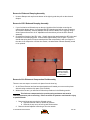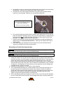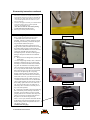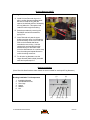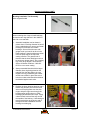
1
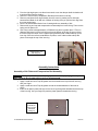
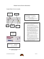
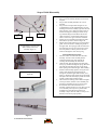
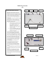
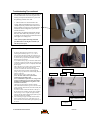
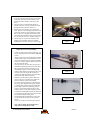
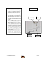
2005 Skareb Service Manual
Rev NC
05 SKAREB SERVICE MANUAL
Page 1
REV NC
Table of Contents
Description
Page
Introduction
3
Front Suspension Terminology
4
Disassembly/ Assembly Instructions
8
Lock Out Troubleshooting
14
Remote Lockout Service Instructions
15
Infinite Travel Adjustment System (IT) Instructions
17
Bushing Removal and Installation Instructions
22
Troubleshooting Chart
26
Skareb: Schematic and Technical Specifications
28
Skareb Service Kit Chart
29
Contact Information
Answer Products Customer Service Department
28209 Ave. Stanford
Valencia, CA 91355
Toll Free:
Direct:
FAX:
E-mail:
Web site:
(800) 423-0273
(661) 257-4411
(661) 775-1798
[email protected]
[email protected]
www.answerproducts.com
05 SKAREB SERVICE MANUAL
Page 2
REV NC
INTRODUCTION
This manual is intended to guide the user through basic service of Manitou Skareb front forks.
Service is supported by the identification of common parts and assemblies that have been
assembled into Service Kits. The purpose of this manual will be to describe conditions that may
drive the need for service and to provide installation instructions for the kits.
Due to the time-consuming nature of suspension fork service, at this time our primary focus is to
offer service kits that minimize the amount of downtime and labor involved.
Important information is highlighted in this manual by the following notations:
WARNING
Failure to follow WARNING instructions could result in severe injury or death to the
person inspecting or repairing the suspension fork or the user.
CAUTION
A CAUTION a caution indicates special precautions that must be taken to avoid damage to
the product.
NOTE
A NOTE provides key information to make procedures easier or clearer
GENERAL WARNING: Suspension forks by design contain gases and fluids under extreme
pressure and warnings contained in this manual must be observed to reduce the
possibility of injury or possible death. Following these instructions can help you reduce
the risk of being injured. Any questions in regards to the information in this manual
should be directed to Answer Products Customer Service at (661) 257-4411.
WARNING Suspension forks use compressed air to provide fluid pressure in the damping
system and spring resistance in Air models. BOTH systems must be relieved of pressure
prior to servicing these systems. Failure to relieve air pressure could result in injury or
possible death.
CAUTION: The Skareb suspension fork uses precision machined aluminum and other soft
alloy components. Using correct tools for assembly is essential to prevent damage.
05 SKAREB SERVICE MANUAL
Page 3
REV NC
FRONT SUSPENSION TERMINOLOGY
Air Cap – Top cap that threads into top of air/spring leg (this is the left leg of the fork as you are
seated on the seat). Forks may be controlled with an air/spring or a coil spring. The air cap
contains the Schrader Valve, which is used to control the spring rate or SAG of air forks.
Air Spring – A mechanism that is used to control the SAG of an air fork.
Arch – A support that connects the two outer lower legs of the casting so as to keep them moving
in unison.
Black Nitrate Leg Coating – New coating for steel stanchion legs that reduces stiction.
Boss – The word used to describe an outer casting that has brake posts for V-brakes or
cantilever brakes.
Bottom Out Bumper – A rubber or elastomer device that absorbs the shock that occurs when a
suspension is compression to its limit.
Bushings – A cylindrical sleeve between a fork stanchion tube (inner leg) and a fork outer
casting (slider), which facilitates the sliding movement between these two parts.
Coil Spring Air Assist – A new feature for 2005 that utilizes a full length coil spring and allows
you to increase the spring rate of the fork by adding air as a booster to that coil spring.
Coil Spring – A coiled piece of metal that acts as a spring to help suspend a fork.
Compression – The phase of the suspension operation in which the wheel travels up, or travels
closer to the frame. The suspension forks reaction to a bump in the trail.
Compression Damping – Restriction of the rate that the suspension compresses under load.
Convertible Travel – A system used to alter the travel of a suspension fork. It requires moving a
travel clip on the compression rod to a different position. This operation is accomplished by
disassembling the fork and physically moving the travel clip on the compression rod.
Crown Steerer Assembly – the stanchion legs (inner legs), the fork crown, and the steer tube
pressed together as one assembly. This assembly is then finished by adding all of the fork
internals and then outer casting (slider).
Damping – A function that modifies the rate of suspension compression or rebound.
Detent – An indentation that causes a rotating adjuster to stop at fixed increments.
Drop Out – The end of an outer casting (slider) where the wheel attaches.
Dust Boot – Usually a piece of rubber in the shape of a cylinder with baffles to allow it to
compress as the fork compresses through its travel. Its function is to help keep dirt and water
from getting into the inner legs of the fork.
FFD – Fluid Flow Damping. A Manitou patented low cost oil damping system. The compression
damping is non-adjustable and the rebound damping may be non-adjustable or adjustable
damping.
Fork Crown – The component that joins the stanchion tubes (inner legs) to the steer tube of the
fork.
05 SKAREB SERVICE MANUAL
Page 4
REV NC
FRONT SUSPENSION TERMINOLOGY (CONT.)
Hydraulic Fork Oil – Oil used in suspension designs to provide damping. It has special
characteristics that determine how it reacts when exposed to compressed air, how it changes
viscosity when its temperature changes, and how it moves through valves.
Hydraulic Lock Out – a condition caused when the mixture of air and damping oil is out of
balance. It is caused when there is too little air space in a chamber, not allowing the fork to
compress through its travel.
Infinite Travel System (IT) – A handle-bar mounted air travel adjust system that allows the rider
to change the fork travel (and ride height) without a spring rate change. The travel can be
changed from full compression to full rebound and at any place in between.
Lock Out – a special function that restricts the compression of the fork from moving. It is
generally controlled by an external knob that is activated when a rider does not want the fork to
move, thus eliminating extra energy needed to overcome the bobbing forces of the fork.
MCU – (Micro-Cellular Urethane) Special urethane that is filled with tiny air cells that act like
springs when the elastomer is compressed.
Micro Lube – Lubrication system that is operated by injecting small quantities of grease directly
into ports that are inserted into outer casting legs. This enables the lubrication of the fork without
having to disassemble it.
No Boss - The word used to describe an outer casting that has no brake posts for V-brakes or
cantilever brakes. This casting is to be used for disk brakes only.
Oil Damping – A system that uses the resistance to oil flow through holes in a valve to provide a
means to alter the rate of suspension compression or rebound.
Oil Level – The level of damping oil needed for the optimal damping performance of a
suspension. It is measured as the air space distance between the top of the stanchion leg (inner
leg) and the height of the oil inside of the leg. The fork must be completely extended in order to
get an accurate measurement.
O-Ring – A soft, flexible neoprene or Buna rubber ring with a round cross-section, which is used
for sealing and retention.
Oil Weight – A description of the relative viscosity of oil, such as hydraulic oil. Oil with low weight
numbers (5wt or 7wt) flows through the valving with less resistance than higher weight numbers
(10or 15 wt).
One Point Five Standard - 1.5 inch interface standard for frame head tubes, headset, cups,
stem, and steer tubes which allows for the lightest weight and strongest design in 170mm single
crown forks. This design greatly improves the control and steering precision of the fork. It is used
predominately on forks with longer travel and the intended use is for more hardcore, extreme
riding.
Outer Casting – (see Slider)
Preload – A condition of compressing a spring or elastomer before the operating loads are put on
the suspension, so that it provides a stiffer spring rate.
05 SKAREB SERVICE MANUAL
Page 5
REV NC
FRONT SUSPENSION TERMINOLOGY (CONT.)
Piston – In front suspension, the part of the damper that slides back and forth inside of the
damping leg that houses the valves. It can also refer to the air piston in the air/spring assembly
that slides back and forth compressing the air, thus causing a change in the spring rate of the
suspension.
Porosity – The condition or property of having pores in a material that will allow gas or liquid to
pass through it.
Platform Plus Damping – A new damping system found on 2005 Rear shocks (featured on
Metel and Radium’s). This system will establish a pedaling efficiency platform similar to SPV, but
is done through unique valving that is not adjustable (helps in bump control).
Rapid Travel II, Wind Down – Systems that are used to control the travel of suspension forks.
Also known as RTII, and WD. RTII is used for the specific purposes of controlling the travel in two
conditions: climbing and descending. WD is an incremental travel adjustment between to set
limits and does not affect the spring rate of the fork as severely as RTII.
Quad Ring seal – New seal that replaces standard o-rings in designs that require more efficient
air and oil sealing methods.
Rebound – The phase of the suspension operation in which the wheel returns to its original
position on the ground after compression.
Rebound Damping – Restriction of the rate that the suspension rebounds when the compression
load is relived.
Remote Lock out system – A handle-bar lever actuated system that controls the lock out
function on front and rear suspension products.
Reverse Arch Technology – Also known as RA. It is a system that is designed to move the arch
of a fork to the backside of a fork, rather than the conventional front position. It was designed to
provide greater rotational torque strength to an outer casting (slider), without adding additional
weight to the fork.
Sag – The amount a suspension fork compresses at rest with a normal load (rider’s weight).
Schrader Valve – Valve used to introduce air into a chamber.
Seal – A part, usually neoprene rubber or Buna, that keeps contaminants out and/or working
fluids in.
Semi Bath – A lubrication system that uses a lubricating oil to keep the bushing surface and
stanchion legs (inner legs) as friction free as possible during movement of the stanchion legs.
Spring Rate – The rate at which the resistance of a spring increases as it is compressed.
SPV – (Stable Platform Valve) new damping system that allows the rider to set the pedaling
platform that he desires to pedal most efficiently in all situations. It is dependent on the pressure
that the SPV valve experiences from the movement of the wheel vs. the terrain and the platform
that is set by pressure introduced to other side of the SPV valve through changes of air pressure
working on the damping oil.
SPV Evolve – The latest version of SPV damping technology that has increased its performance
with modifications to the original design.
05 SKAREB SERVICE MANUAL
Page 6
REV NC
FRONT SUSPENSION TERMINOLOGY (CONT.)
Slider/Outer Casting – The tube (outer casting leg) of the suspension fork that0. remains fixed to
the wheel. It slides up and down on the stanchion leg (inner leg).
Stanchion Clamps - (Double-Triple Clamps) the portions of the fork crown that clamp around the
stanchion legs above and below the head tube of the bicycle frame on specific long travel
applications.
Stanchion Legs – The suspension tube (inner leg) fixed to the fork crown. It remains stationary
during the operation of the suspension.
Steer Tube – The long cylindrical tube that extends from the top of the fork crown. Its function is
to be inserted into the bicycle head tube and attach the suspension to the bicycle frame.
Thru Axle – (Hex-lock) A device used for mounting a thru axle hub to special outer legs that are
not made for standard quick release hubs. Manitou’s Hex-lock (thru axle) system is a special
patented system utilizing a hex shaped end that increases the stiffness of the fork and reduces
slippage in the joint between the axle clamps and the axle.
Top Out Bumper – A rubber, coil spring, or elastomer device that absorbs the shock that occurs
when the load is taken off a suspension so that it is allowed to rebound to its limits
TPC – (Twin Piston Chamber) a patented damping system that has independent pistons for
rebound and compression. The system utilizes a mixture of air and oil in the damping leg of the
fork to enhance the damping performance.
TPC+ - A variation of TPC that has added a floating piston to the compression damper to
enhance the performance of the compression damping under the load of bigger hits.
Travel – The amount that a wheel moves between the most compressed and the most extended
states of the suspension
Viscosity – A description of how a liquid flows. Liquids with higher viscosity are thicker flow less
easily or quickly than liquids with low viscosity. This has an affect on the damping speeds of
rebound and compression.
Volume Control – A new system designed to work with SPV as a control of the compression
ramp up rate of the fork. It has a range of adjustments from linear to very progressive.
Wiper Seal – A rubber material that is used as a seal to keep dirt and water out of the outer
casting legs. It is not designed to keep air pressure or extreme oil pressure in. Manitou has the
new Evil Genius wiper seals.
05 SKAREB SERVICE MANUAL
Page 7
REV NC
2004 Skareb Forks Disassembly and Rebuild Instructions
Disassembly Instructions
Removal of Outer Casting
1. From the left leg dropout (Left when sitting on the bike), use a 4mm hex wrench to
remove the compression rod screw.
2. From the right leg dropout, if the fork has adjustable rebound, the knob will need to be
removed. Remove the 2mm hex screw inside the knob and remove the knob.
3. Use a 8mm hex wrench to turn the damper clockwise until it can be pushed into the
casting.
4. Remove crown/steer/inner leg assembly from the outer leg casting.
5. Position the bottom of the fork legs over a drain pan that is on the ground. Pull the
casting downward towards the pan, allowing the Semi Bath oil in the casting to drip into
the pan. Pull the casting completely off of the inner legs and wipe any excess oil off of
inner legs and inside of casting.
Bushing Removal & Installation
Please refer to section on Bushing Removal & Installation.
Removal of Compression Damping Assembly
Forks with FFD (non-adjustable) Damping
1. Remove top leg cap (FFD Assy) on right hand side using 27mm socket.
2. Pour old oil out of the top of the fork, then compress fork upside down over oil drain pan
3-5 times to get oil out from under rebound piston and discard appropriately.
Forks with Adjustable Compression/Lockout Damping
1.
2.
3.
4.
Remove the 2mm fixing screw on top of the damper knob on top right side of the fork.
Remove 2 balls and springs from inside the top cap.
Unscrew the compression damping assembly using a 24mm socket.
Pour old oil out of the top of the fork, then compress fork upside down over oil drain pan
3-5 times to get oil out from under rebound piston and discard appropriately.
Removal of SPV Compression Damping Assembly
WARNING This fork uses compressed air as part of the SPV damping system and must be
relieved of pressure prior to servicing. Failure to relieve air pressure could result in injury
or possible death.
1. If your fork has a red Schrader cap on the top right side of the fork, it is equipped with SPV
damping. Remove Schrader valve dust cap from Red Hex Shaped Top Cap on the top right
of the crown. Release all air pressure from the Schrader valve.
2. Remove SPV Volume Control Cap (Red Hex Shaped Top Cap) from top right of the crown
with a 24mm Socket. Turn fork upside down over drainage pan to empty Damping oil from
the inner leg. Stroke the Damper shaft on the bottom of the inner leg 3-5 times to purge the
leg of oil that is caught below the oil piston.
05 SKAREB SERVICE MANUAL
Page 8
REV NC
Removal of Rebound Damping Assembly
1. Unscrew Damper end cap from the bottom of the right leg and then pull out the rebound
damper.
Removal of SPV Rebound Damping Assembly
1. If your fork had a red Schrader cap on the top right side of the fork when removing the
compression damper above, it is equipped with SPV damping and will have the companion
SPV rebound assembly. Unscrew damper end cap from the bottom of the right leg using a
24mm Open-end wrench or 8-10” Adjustable wrench and then pull out the SPV rebound
assembly.
2. Checking the function of the SPV valve - Visually inspect the gap between the SPV valve and
the bottom of the damping piston. It should have approximately 1mm of space. The valve
should also spring back to its open rested position after compressing it with your fingers. If
the valve is not responsive or all the time closed, it is bad and the rebound assembly needs
to be replaced.
Check for 1mm gap
between the blue
SPV valve and the
black piston
Removal of Air Piston and Compression Rod Assembly
There are now two ways to remove the air piston from the inner leg.
1. An Air Piston Removal tool has been developed that will enable you to remove the piston
without having to take the fork apart. (P/N: 85-8062).
2. Without this new tool, you will need to follow the procedures in the following section.
WARNING This fork uses compressed air to provide spring resistance and must be
relieved of pressure prior to servicing. Failure to relieve air pressure could result in injury
or possible death.
1. Remove air dust cap covering the Schrader valves.
a. Depress Schrader valve to release air pressure.
b. Remove air cap on top of Left leg with 20mm socket.
2. Remove rebound adjuster knob using a 2mm hex wrench.
05 SKAREB SERVICE MANUAL
Page 9
REV NC
3. From the right leg dropout, use 8mm hex wrench to turn the damper shaft clockwise until
it can be pushed into the casting.
4. Remove 11mm hex bolt (Compression Rod bolt) from bottom of Left leg.
5. Remove crown/steer/inner leg assembly from the outer leg casting over a drain pan,
because Semi Bath oil will leak out of bottom of casting once you pull the inner legs from
the outer casting legs.
6. Be sure to drain all Semi Bath oil out of casting before re-assembly of fork.
7. Remove left leg end cap and compression rod assembly from inner left leg. Then remove
spring and Air piston rod.
8. Use a long narrow rod approximately 18”/458mm long and no greater than ¼”/7mm in
diameter and insert it into the left inner leg from the bottom of the leg. Be sure to direct
the rod through the center of the negative spring assembly that is about halfway up the
inner leg. Once the rod has contacted the air piston, use a rubber mallet and tap the
piston out through the top of the inner leg.
Tapping Piston out
with long rod
Assembly Instructions
Assembly of Air Piston and Compression Rod Assembly
WARNING All leg caps for Damper and Spring systems must be properly tightened prior to
use. Failure to do so could result in injury or possible death.
1. Apply a small amount of Prep M grease onto the threads at the top of the left inner leg
with your finger.
2. Apply a small amount of Prep M grease around the outside diameter of the new air
piston.
3. Insert the air piston (metal side up) into the inner leg through the threaded area at the top
of the inner leg. Use your fingers to push the piston past the threads into the leg.
Air Piston is
inserted into
inner leg with
metal side
facing up
05 SKAREB SERVICE MANUAL
Page 10
REV NC
4. Re-install the air push rod, positive spring (that has been well greased), and compression
rod assembly. Tighten per the Fastener and Torque Values section.
5. Pour about 3cc of a 40wt or greater automotive oil into the top of the piston and then
install the air cap assembly. Tighten the air cap assembly 30-50in/lbs.
Make sure to apply a thin layer of
grease to inner threads and outside of
piston before installation.
Pour 3 cc of oil into top of piston
6. Fully extend the damper shaft and slide the rubber bumper against the inner leg end cap.
Insert the crown/steer assembly into the outer legs to the upper bushing. Holding the fork
horizontal, inject 16cc of 5-40wt Semi bath oil into the hole at the bottom of each outer
leg (Figure 2). A syringe works well for this procedure.
7. Push the outer legs past the lower bushing and reinstall the 4mm bolt and tighten 8mm
damper fitting in a counterclockwise direction. Tighten per the Fastener and Torque
Values section.
8. Use a shock pump (p/n 85-4069) to fill the air system to the recommended levels as
outlined in the Fastener and Torque Values section.
Reassembly of Crown Steer/Leg Assembly
WARNING All top caps for Damper and Spring systems must be properly tightened prior to
use. Failure to do so could result in injury or possible death.
WARNING All leg caps for Damper and Spring systems must be properly tightened prior to
use. Failure to do so could result in injury or possible death.
1. Grease the outside of the air piston and then apply a thin film of grease to the threads at the
top of the inner leg. It is recommended to use Prep M grease (P/N: 85-0031). Push the piston
into the top of the left inner leg with the metallic side of the piston facing you, using your
thumb. Push the piston past the threads and then pour approximately 3-4cc’s of a 20-50wt oil
(P/N: 85-0022) into the top of the piston. This oil needs to be checked about every 6-8 weeks
of riding time. It will dissipate over time and then you may experience some air leakage and
increased stiction in the fork movement.
2. Install the air cap and tighten it to value given on fork schematic.
3. Turn crown/steer/leg assembly over, so that the bottoms of the inner legs are facing you. In
the same leg that you just installed the air piston and air cap into; insert the air push rod
(longer end in first), then the positive spring (this is your ride kit spring) onto the short end of
the push rod, then install the compression rod assembly, and tighten end cap into leg.
Tighten to torque values that are listed on fork schematic.
4. Now, install damping assembly into bottom of other inner leg. If your fork uses SPV damping,
be sure to check the function of the SPV valve and apply a thin layer of Prep M grease onto
05 SKAREB SERVICE MANUAL
Page 11
REV NC
o-ring that is around the piston at top of assembly. Install the assembly and tighten end cap
to specified torque value.
Assembly of Compression Damping Assembly - Non-Adjustable FFD
WARNING All top caps for Damper and Spring systems must be properly tightened prior to
use. Failure to do so could result in injury or possible death.
1. Put a little bit of Prep M grease (Ref Answer Products PN 85-0031) on o-ring found on
the lower piston of the FFD assembly.
2. Install the FFD Assy into the top right hand of the crown/steer using a 27mm socket.
Tighten per the Skareb Schematic and Torque Specification Table.
Assembly of Compression Damping Assembly - Adjustable Compression/Lockout
WARNING All top caps for Damper and Spring systems must be properly tightened prior to
use. Failure to do so could result in injury or possible death.
1. Fill right leg with damping oil using 5wt Motorex fork oil (Ref Answer Products PN 850023) to the height noted in the Skareb Schematic and Torque Specification Table. Cover
the opening at the top of the right leg of the crown/steer with a rag and cycle the fork six
times. Recheck oil level and add/drain to meet the level requirement.
2. Put a little bit of Prep M grease (Ref Answer Products PN 85-0031) on the urethane or
brown rubber o-ring found on the lower piston of the Lock out assembly.
3. Twist the Hex shaped aluminum shaft that sticks up from the top cap counter clockwise
until it stops (the system is completely open to oil flow at this point).
4. Using a motion like screwing in a screw. Twist the assy. and apply a little pressure to
insert the piston part of the mechanism past the threads at the top of the inner leg. Then
push the assy. into the leg until the threads on the cap intersect the threads inside the
inner leg, screw the cap. Tighten per the Skareb Schematic and Torque Specification
Table.
5. Once the cap is tightened, twist the Hex shaped shaft clockwise until it stops (this is the
locked out position). Insert the springs into opposite holes in the top cap and then place
the ball bearings on top of the springs (place a little dab of grease on spring to hold ball
bearing in place).
6. Place the adjuster knob onto the hex shaped aluminum shaft and seat it onto the top cap
and ball bearing. Position the adjuster cap so that the lever part of the cap is at the
farthest point to the back of the crown.
7. Insert 2mm fixing screw and tighten to secure the knob. Twist the knob counter clockwise
to activate the fork suspension. Compress the fork several times to circulate the oil
through the system and then activate the Lock out system by moving the lever clockwise
to its stopping point at the back of the crown. The fork should have approximately 5 mm
of progressive travel before it locks out.
Note: This system is a combination of adjustable compression damping that becomes a lock
out. It is fully active when the lever is facing all the way forward (counter clockwise) and
locked out when the lever is facing all the way towards the back of the crown (clockwise).
Assembly of Compression Damping Assembly - SPV
WARNING All top caps for Damper and Spring systems must be properly tightened prior to
use. Failure to do so could result in injury or possible death.
1. Insert the Volume control assembly into the top of the right inner leg and tighten per the
Skareb Schematic and Torque Specification Table. Be sure that you unscrew the red
05 SKAREB SERVICE MANUAL
Page 12
REV NC
16mm Hex shaped Volume control nut all of the way counterclockwise after you tighten
the entire assembly into the inner leg. Use: the Manitou Volume Control Adjuster (P/N:
85-3007) to do this.
Installation of Outer Leg Casting
WARNING When installing the outer Leg Casting to the Crown Steer Assy, Compression
Rod bolts and Damper Shafts must be properly tightened prior to use. Failure to do so
could result in injury or possible death.
1. Turn completed crown/steer/leg assembly upside down, so that the compression rod and
damper shaft are facing you. You will see a bottom out bumper on the damper shaft; slide
this bumper down towards the end cap that is threaded into the inner leg. This will help in
keeping the shaft extended as you install the outer casting.
2. Pressurize the air spring to 100psi; this will help keep the compression rod extended as
you install the outer casting.
3. Press inner legs into casting about half way and then inject Semi Bath oil (5/40wt.
synthetic oil, P/N: 85-0022) into outer casting, holding fork at 45 degree angle to the
ground with bottom of fork in the air (drop outs up). Inject 16cc’s of oil into each outer
leg. It is recommended to use a syringe to inject oil.
4. Finish sliding inner leg assembly into outer leg casting until damper shaft contacts
casting.
5. Use an 8mm hex wrench to turn the damper shaft counterclockwise, threading it into
the casting. Tighten per the Skareb Schematic and Torque Specification Table.
6. Install rebound adjuster knob if applicable. Knob should turn uninhibited until the
indicator is stopped by the casting. If not, remove knob and reinstall on hex shaft in 1/6
turn increments until full travel is reached.
7. Install the 4mm compression rod screw and tighten per the Skareb Schematic and
Torque Specification Table.
05 SKAREB SERVICE MANUAL
Page 13
REV NC
Lock Out Troubleshooting Tips
Installation of Lock out Compression Damping System
• Check the o-ring that is installed around the lower piston on the damper shaft for
tears or deformation. Replace it, if it is damaged. This is the most common reason
why the Lock out system will not function.
• Check the level of oil in the inner leg. The oil level may be a little high, but never
low. The oil level must be high enough to cover the window that opens and closes on
the damper shaft.
• Make sure that the oil flow window on the lower portion of the damper shaft,
positioned right above the piston, opens and closes when you move the lock out knob
from open to close.
• Inspect the rubber o-ring that is around the threaded portion of the cap that screws
into the inner leg of the fork. This o-ring should not have nicks or tears in it and
should fit tightly around the cap.
• Make sure that when installing the Lock out system into the fork leg that you follow
this procedure: Put a little bit of Prep M grease on the urethane o-ring, make sure that
that the oil flow window is open using a motion like screwing in a screw. Twist the
assy. and apply a little pressure to insert the piston part of the mechanism past the
threads at the top of the inner leg. Then push the assy. into the leg until the threads on
the cap intersect the threads inside the inner leg, screw the cap in and do not use any
tools to over tighten the cap. Once the cap is tightened, compression the fork several
times to circulate the oil through the system and then activate the Lock out system by
moving the lever to the other position. The fork should have between 2 & 5mm of
progressive travel before it locks out.
1.
Troubleshooting
• If the Lock out does not lock out properly, go back through the steps listed above.
• If the o-rings are damaged on the Lock out piston, replace them with P/N
062594(urethane 1998-2003 Mars, SX, & Skareb Lock outs), 065261 (04/05
Skareb Lockouts) and 02/03 Black 100/120mm Lock outs, and 040315 (Axel’s).
• If the oil level is low, check to see if there is evidence of leaking at the Rebound
Damper. If so, replace the Rebound Damper assembly and retry the Lock out. The oil
level may be low if you are upgrading a standard Compression Damping system with
the Lock out system. In this case, make sure the oil level is at the correct level before
trying it again. If there are signs of oil leaking around the top of the Lock out system,
check the rubber o-ring (040524) and replace if needed. If the window does not open
or close when the knob is moved, replace the entire Lock out assembly.
05 SKAREB SERVICE MANUAL
Page 14
REV NC
Remote Lock out Service Instructions
Complete Remote Lock out Assembly
Lever Kit and
Lever cover
Kit
Cable Guide
There are (5) Service kits available for each fork
model that utilizes a Remote Lock out.
1. Lever assembly
2. Lever Cover
3. Cable assembly
4. Cable guide
5. Lock out assembly
*Reference to these kits may be found in the
Service Parts Matrix
Instructions for removing assembly from fork
Barrel
adjuster
Cable
Assembly
1.
Lock out
Assembly
2.
3.
Tools needed
to service
assembly
4.
5.
Unscrew barrel adjuster in a
counterclockwise direction until it stops.
Remove Lever cover by squeezing the two
plastic prongs together on the under side of
the lever and pulling the cover in an upwards
direction from the lever assembly.
Pull on Black cable ferrule nearest to lever
and pull cable assembly from the groove in
the Lever assembly, thus releasing cable
from lever. Unhook cable end from lever.
Unscrew the top cap of the Lock out
assembly from the fork crown using socket
(Answer p/n: 83-2503) or an adjustable
wrench.
Pull Lock out assembly out of crown by
twisting the assembly like unscrewing a
screw and applying an upward pressure.
Slowly pull assembly out of crown and watch
out for some excess damping oil to come out
of inner leg as the piston at the end of the
assembly comes out of crown.
Adjustable Pliers
Adjustable Wrench
Socket Wrench
22mm Socket
W/cut out
10mm open end wrench
Please continue to next page for more
Service instructions
05 SKAREB SERVICE MANUAL
Page 15
REV NC
Steps of Cable Disassembly
1.
2.
3.
Step 3
Step 1
Step 2
4.
5.
Tool Placement to unscrew upper
shaft assembly from lower
assembly (Figure A)
1.
2.
3.
Cable hook up connection
(Figure B)
4.
5.
Cable Replacement Instructions
Step 1: Lock out assembly should be out of fork at
this point.
Step 2: Cable assembly should be out of Lever
assembly
Step 3: Look at tool placement in Figure A. It is
recommended to use the Adjustable Pliers to grasp
the flange of the lower assembly right above the coil
blow off spring. Use a 10mm open end wrench on
the flats of the upper assembly just below the top
cap. Hold the flange with the Pliers and turn the
10mm wrench in a counterclockwise direction in
order to unscrew the upper and lower assemblies.
Separate the two assemblies and unhook the cable
end from the eye hook as shown in Figure B.
Pull the cable out through the top cap and red cable
guide. There will also be a 75mm spring inside of
the upper shaft. This spring provides the tension for
the cable when you move the Lock out lever from
the Lock position to Unlock position. The inner
cable runs through the center of the spring.
Cable Installation Instructions
The inner cable is not removable from the cable
assembly. The entire cable assembly must be
replaced. Install the new cable assembly by
reversing the Disassembly the instructions.
Slide the inner cable through the red cable guide,
the top cap, and down through the spring. (Be sure to
put a little bit of the Prep M grease on the spring
before putting it back into the upper shaft assembly.)
Push the cable assembly together, forcing the inner
cable to stick through the spring and then out
through the end of the upper shaft assembly. (See
Figure C). Hook the cable end into the eye hook and
then pull on the cable assembly to pull the two shafts
together. Tighten them together snuggly.
Check oil level in fork leg (refer to oil level heights
in fork spec sheets). Install Lock out assembly into
the fork leg and tighten top cap to proper torque.
Re-install the other cable end into the Lever
assembly, and then put the lever cover back on to the
Lever assembly. You may have to pull the cable
assembly away from the housing of the lever
assembly to expose the inner cable, so that you can
slide the cover into its proper position.
Figure C
05 SKAREB SERVICE MANUAL
Page 16
REV NC
Infinite Travel System
(IT)
Lower
Assembly
IT System Disassembly Instructions
1.
2.
3.
4.
5.
6.
7.
8.
9.
Remove front wheel and brake set from fork.
Important: you must remove all of the air from
the left leg of the fork before disassembling the IT
System. There may also be a discharge of a white
substance when you depress the Schrader valve
core (this is similar to the discharge when you
depress the valve core on any of the Manitou Air
or SPV forks).
On the bottom of the left leg (leg that has the Disk
Brakes mounts on it), there is a Schrader valve
protruding from it. Unscrew the valve cap and
follow either of these two methods for releasing
all of the air from the system.
A. Depress the valve core and let all of the
air out. Now depress the IT lever on the
bike’s handlebar and release it. Once
again, depress valve core in the
Schrader valve to release any air in the
leg. Do this a couple of times, until all
of the air is released.
B. If you have a helper, have them hold the
IT lever on the handlebar down as you
depress the valve core. This will let all
of the air out at one time.
Now that all of the air is released, unscrew the
12mm nut that is threaded onto the Schrader
valve. It is recommended to either turn the fork
upside down or hold it right side up over a drain
pan to catch the Semi Bath lubrication oil that will
come out of the bottom of the casting as you start
the procedure of removing the casting. (see Fig 1)
Move over to the bottom of the right leg and
unscrew the 2mm Allen screw from the middle of
the rebound adjuster knob. Pull the knob away
from the bottom of the casting leg exposing a
recessed 8mm hex.
Use an 8mm Allen Wrench and turn it in a
clockwise direction in order to unscrew the
rebound damper shaft from the casting.
You can now remove the casting, exposing the
fork’s inner legs. Be aware that there may be
some of the Semi Bath oil in the casting after you
remove it.
Use an Adjustable Wrench and unscrew the black
end cap that is threaded into the bottom of the left
inner leg.
Pull the lower IT assembly from the inner leg.
There may be a very little amount of oil that
comes out of the inner leg as you remove the
lower IT assembly. This is the lubricating oil used
to allow the air piston on the lower shaft assembly
to move freely.
05 SKAREB SERVICE MANUAL
Air Piston
Upper
Assembly
IT Lever
Assembly
Top Cap &
Cable Guide
Inner & Outer
IT control wire
IT System Components
22mm slotted socket
Adjustable Wrench
12mm
Wrench
Valve
Core Tool
Service Tools Needed
Page 17
REV NC
Disassembly Instructions continued
10.
Now it is time to remove the IT upper assembly.
Release the IT control wire from the control lever by
unscrewing the fixing screw on the lever that holds the
cable tight. Use a 2mm Allen Wrench to unscrew this
screw and then pull the cable out of the lever. (Go to
Fig 2 for next step)
11. To remove the upper IT assembly, use a slotted 22mm 6
point socket (P/N: 83-2503), a 22mm Open End
wrench, or an adjustable wrench.
(Note: Be aware of the IT control Wire spinning
around when unscrewing the top cap)
12. Pull the upper assembly out of the inner leg.
Troubleshooting Tips
1.
Figure 1
Here is a guide to help pinpoint fork travel issues.
** If the fork starts to lose travel from an
extended position to a shorter position by itself,
the damage is most likely centered on the Quad
ring around the outside of the piston.
**If the fork extends from a shorter travel to a
longer travel by itself, the failure can be involving
the smaller Quad ring that is located under the
piston on the inside diameter of it where the shaft
of the upper assembly intersects the lower
assembly and piston. The shaft is sealed against
leakage at this point to define the two different
chambers.
A. Always check two things when you have the
system apart.
***Use a straight edge and lay it next to the inner
shaft that is attached to the top cap of the upper
assembly to insure that that shaft is not bowed at
any point. We found that on assembly of these
pieces, the shaft is pressed into the top cap and if
it is over pressed, the shaft will bow. This means
that at where the bow is in the travel of the shaft,
it will cause the Quad ring that it is passing
through, to distort. Thus air transfers from one
chamber to the other and the fork will extend by
itself. If this is the case, you will need a new top
assembly and an O-ring kit. (Refer to Figure 3)
***Make sure that the valve core in the Schrader
valve is tight and does not stick open or closed. If
this is faulty, replace this valve core with a new
one. Any bicycle tube valve core will work, as
well as any valve cores that we currently use on
any of our other products.
B. On the lower assembly, inspect the Quad ring
that is around the piston at the top of the lower
assembly. You are looking to see if it is seated
properly and not torn or twisted. Also inspect the
piston to see if there are unusual wear marks on
the piston on one side of the piston only.
If this is a wear spot, then this means that the hole
in the bottom of the casting is slightly off center
and the casting needs to be replaced with a new
one. (Refer to Figure 4)
(Continued on next page)
Figure 2
Figure 3
Figure 4
05 SKAREB SERVICE MANUAL
Page 18
REV NC
Troubleshooting Tips continued
This condition causes the Lower shaft assembly to
be side loaded inside of the inner leg and causes
wearing of the piston that allows for a poor fit of
the Quad ring and thus an air leak
C. The last item to be concerned with is the
casting. When reassembling the fork, be sure to
visually inspect the position of the bottom of the
lower assembly as it begins to come through the
bottom hole in the casting before you secure it
with the 12mm nut.
If that shaft is not guiding itself straight through
that lower hole without any assistance, you will
eventually see the same issue as mentioned above.
Once again it is a casting issue.
(Note: Always replace all o-rings and seals
provided in the IT O-ring kit, each time you
take the system apart)
IT Control Wire Change
1.
In order to change the inner control wire, start by
following IT disassembly steps 2, 3, 10, 11, & 12.
2.
Once you have the upper assembly out of the fork, use
the adjustable wrench and the 12mm Open End wrench
to unscrew the top cap from the shaft of the assembly.
Refer to Figure 5 at the right.
3.
As you unscrew the top cap, you will feel a little tension
created by a spring that is under the cap. Separate the top
cap from the shaft once you have completely unthreaded
the two pieces.
4.
Pull on the inner wire in order to remove the machined
stopper with the cable end in it from the shaft.
5.
You can now unhook the cable from the stopper and
from the cable head end, pull the cable through the
spring, the top cap, and the outer cable housing. Refer to
Figure 6 at the right.
6.
Reverse the above steps to replace the cable.
(Note: The inner cable can be replaced with a
standard bicycle Derailleur cable)
(It is recommended to replace the two O-rings on the
stopper each time that it is removed from the shaft,
in addition to the Black Buna O-ring that is on the
shaft below the threads.)
7.
Tighten top cap on the shaft to 25inlbs (2.85Nm).
8.
Put a small amount of Motorex grease on the end of the
Upper Assembly shaft, and then insert the assembly into
the fork inner leg.
9.
As soon as contact is made with the hole in the top of
the air piston/lower assembly, twist the upper assembly
like screwing in a screw to guide the upper assembly
shaft into the hole without damaging the Quad ring seal
in the shaft of the lower assembly.
10. After reinserting the upper assembly into the fork but
before screwing the top cap in, pour about 6-8cc’s of
40wt. automotive oil into the fork leg through the top of
the crown.
Figure 5
Top Cap
Spring
Machined Stopper
Shaft with Buna O-ring
Figure 6
05 SKAREB SERVICE MANUAL
Page 19
REV NC
11. Feed the inner wire through the cable housing and
secure one end of the of the housing into the gold
cable guide, then feed the end of the inner wire
through the hole in the black cable stop on the
lever.
12. The inner wire now feeds through the hole in
bottom of the lever, over the top of the lever and
through the hole in the back of the lever.
13. Pull the inner wire until there is no slack in the
cable. Be sure to set a 2mm gap between the front
of the lever and the top of the cable stop to insure
7
gap
that you have notFigure
over tightened
the cable2mm
before
you tighten the 2mm Allen bolt on the front of the
lever to cinch the inner wire. (Refer to Figure 7)
14. The last step is to cut the inner wire that is left
hanging on the backside of the lever and then
installing the cable end to prevent it from fraying.
Figure 7
2mm
Gap
Replacement of Piston Quad Rings
1.
2.
3.
4.
5.
6.
7.
In order to replace the Air piston Quad rings, you
need a 12mm Open End wrench and an adjustable
wrench.
Refer to Figure 8 for wrench placement. Hold the
12mm wrench in place on the flats that are on the
piston seat and turn the piston with the adjustable
wrench in a counter clockwise motion to unscrew
the piston from the shaft.
Once the piston is off of the shaft, you will see a
small Black Quad ring inside the top of the shaft
that you just unscrewed the piston from. Use a
small diameter object to remove the Quad ring
from the shaft. Replace this Quad ring with a new
one from your IT O-ring kit. Be sure that it is
seated in the shaft and rests flat against the shelf
inside of the shaft. (Refer to Figure 9)
Install the Air Piston back onto the shaft in the
reverse of the way you removed it. Tighten the
piston to 15inlbs (1.7Nm) onto the shaft.
To remove the large Quad ring on the outside of
the piston, grasp the piston at the Quad ring like
you would pinch someone with your thumb and
pointer finger. Squeeze the Quad ring and you
will see a section of the Quad ring move away
from the piston. Use the same tool that you used
to remove the small Quad ring from the shaft and
pry the Quad ring off of the piston, being careful
not to scar the surfaces of the piston.
Discard this Quad ring and replace it with a new
one. Be careful not to twist it in the seat that it
rests in.
You are now ready to reassemble the IT system.
Figure 8
Figure 9
Note: Always change all Quad rings and orings when servicing the IT system
05 SKAREB SERVICE MANUAL
Page 20
REV NC
Reassembly of the IT System
1.
2.
3.
4.
5.
6.
IT Service Kits
It is recommended that when reassembling the
IT system that you start by installing the lower
assembly into the bottom of the inner leg first.
Be sure to apply a small amount of Prep M
grease to the Quad ring on the outside of the
piston and onto the threads of the inner leg
before inserting assembling into leg.
Twist shaft assembly as you insert piston past
the threads of inner leg. Tighten end cap to 2535inlbs (2.8-3.9Nm).
Refer to steps 8, 9, and 10 above in the “IT
Control Wire Change” for installation of the top
assembly.
Once this assembly is installed; the casting can
be installed, Semi Bath oil added, and all
fasteners secured.
When re-inflating the IT system, it is fastest if
you have someone depress the control lever and
hold it while you pump air into the system. This
way the system equalizes immediately. If you
do not have a second person to help, just add air
to the system and then periodically depress the
lever to equalize the pressure. This may have to
be done a couple of times in order to reach the
required air pressure.
It is recommended to initially set your fork up
with an air pressure that is approximately 75%
of your rider weight. Then you can fine tune
your ride by adding or deleting air as you need.
Lever Kit
Assembly
Lower
Assembly
05 SKAREB SERVICE MANUAL
Page 21
Cable
Guide
Top Assembly
REV NC
Bushing Removal & Installation
Bushing Removal
(Note: use appropriate removal ring that corresponds to the leg diameter of the fork being
repaired)
Leg Diameter
25.4mm (1”)
28.6mm (11/8”)
30mm
32mm
Answer Kit #
85-5191
85-5189
85-5194
85-5192
Bushing Removal Tool Components
A. Slide Hammer
B. Threaded Handle
C. Slide
D. Threaded Shaft
E. Removal Ring
Bushing Removal Tool Assembly
05 SKAREB SERVICE MANUAL
Page 22
REV NC
Bushing Removal (CONT.)
Bushing Removal Instructions
A. Install 25.4mm Removal ring on the
shiny, smaller diameter threaded shaft.
Be sure to install the ring with the
tapered, chamfered end first, followed by
the long slide tube. This tapered end
leads the tool through the bushing.
B. Start the procedure by removing the
Dust/Wiper seal with a screwdriver,
prying it out.
C. Insert Removal tool past the upper
bushing and then stop. It is important to
pull one bushing out at a time. Push the
slide on the threaded shaft down
towards the removal ring. Hold the
casting with one hand and the slide
hammer with your other hand. Now
move the slide hammer in a motion away
from the casting and repeat this action
until the bushing comes out.
D. For all other leg diameters: use the
larger diameter (dark colored) threaded
shaft and repeat steps A-C.
Bushing Installation
(Note: Sizer kits listed in above chart contain the sizers needed for each specific leg diameter.)
(1)
(2)
Bushing Installation Tool Components
1. Installation Mandrel
2. Threaded Rod w/nuts
3. Sizer rings
4. Spacer
5. Washer
6. Nut
(3)
05 SKAREB SERVICE MANUAL
Page 23
(4) (3) (5)
(6)
REV NC
Bushing Installation (CONT.)
Bushing Installation Tool Assembly
With weighted handle
When selecting sizer rings to install bushings,
choose the two rings that are in the middle of
the size run to start with.
1. Assemble installation tool as shown in
picture above. Each leg diameter kit has all
of the needed pieces to remove and install
bushings for forks with serviceable
bushings. Some of the kits come with
gauges to tell you how far to drive in the
lower bushings. Upper bushings are driven
in as far as the stop in the top of the
casting will allow. The general rule of
thumb is that the lower bushings must not
be driven any deeper than 5” into a casting
leg. If they do go deeper, call Customer
Service at Answer Products – 800-4230273 for a new outer casting.
2. Always assemble Mandrel with the larger
diameter sizer ring being placed on the
mandrel first, then the spacer, the next
largest sizer ring, followed by the washer
and the nut to hold it in place. Be sure to
lock the nut above the Mandrel and below
the Mandrel against each other.
3. Replace the lower bushing (bushing with a
thicker wall diameter) first. Place a small
amount of Prep M grease onto the sizer
rings to help the rings come through the
bushings when pulling them out. Slide
bushing onto Mandrel until it stops. Apply
a bead of Red Loctite all the way around
the outside of the bushing. Hold casting on
top of bench with a rag under the end of
the legs and insert installation tool with
bushing into casting leg.
05 SKAREB SERVICE MANUAL
Page 24
REV NC
Bushing Installation (CONT.)
4. Slide weighted handle onto end of threaded rod and tap rod into casting with rubber Mallet
until proper depth is achieved. If using depth gage, slide gage onto rod before installing
weighted handle and let it settle on of Mandrel. Tap rod until appropriate line on gage is even
with top of casting leg.
5. Remove weighted handle and gage (if applicable).
6. For sizing of the lower bushing:
7. Use slotted top cap from sizer kit and set it into the top of the casting leg, straddling the
threaded rod. Spin the extra nut with washer down to the top cap and using a wrench,
socket, or speeder wrench, tighten the nut in a clockwise direction. This will cause the
Mandrel to be pulled through the bushing, thus sizing it. Keep turning the nut until the tool is
all the way through the bushing and can be pulled out of the leg.
8. To install top bushings, repeat steps B-E. Note that the top bushing gets inserted until it stops
against the step inside of the casting. The extra sleeve that comes with the sizer kit is used
to space the top cap off of the casting, so that there is enough room to pull the sizers out of
the casting without bottoming on the cap.
9. If you find that the bushings are too tight after installing them, use the sizer Mandrel that does
not have a stop on it to hold the bushing while installing it into the casting. This is available in
the 25.4mm leg kit (85-5191) to go back in and resize the bushings.
10. To resize bushings, Choose the next larger size rings and repeat the above process.
11. When satisfied with the results, reinstall Dust/wiper seals and then reassemble fork
05 SKAREB SERVICE MANUAL
Page 25
REV NC
TROUBLESHOOTING
Symptom
Air Loss
Oil leaks from
Wiper Seals
Oil leaks from
bottom of
Casting
Lack of Travel
Loss of SPV
damping
Cause
Service
Manual
Page
Solution
Schrader Valve leaks
Tighten Valve core, replace bad parts as
needed.
10
Air Cap O-ring leaks
Make sure O-ring is seated properly,
replace parts as needed.
9
Air Piston leaks
Check oil volume on top of piston, replace
parts as needed.
9
Air Top Cap leaks
Check O-ring, tighten cap to proper
Torque, replace parts as needed.
9
Seal not seated properly
Remove Casting from Inner Legs, reinstall
or replace seals
8
Nicks or scratches on
inner legs
Replace Crown/Steerer/Inner Leg
Assembly
8
Too much Semi Bath oil
Follow instructions for removal and
installation of Outer Casting
13
Wear
Remove Casting from Inner Legs, reinstall
or replace seals
8
Rebound damper shaft
leaks
Replace Rebound Damping assembly
9
Rebound damper shaft Oring damaged
Replace O-ring on threaded end of
Rebound Damping assembly
9
Compression Rod Bolt
leaks
Check O-ring on bolt to see if it is
damaged and then reinstall
8
Tight Bushings
Hydraulic lock out
Resize bushings or replace with new ones
if damaged
Replace Rebound Damping assembly
22
9
Semi Bath oil volume
Follow instructions for removal and
installation of Outer Casting
13
Damper oil volume
Check oil level, Replace Rebound
Damping assembly if needed
12
Fork alignment
Visually inspect fork, call Answer
Products Customer Service
2
SPV valve not functioning
Inspect for damage, check valve gap,
replace assembly if needed
8
Damper oil volume
Check oil level, refer to "Oil leaks from
bottom of Casting"
12
Rebound knob does not
turn
Replace Rebound Damping Assembly
9
Loss of SPV air pressure
Refer to "Air Loss- Schrader valve leaks
and Air Cap O-ring Leaks"
9
05 SKAREB SERVICE MANUAL
Page 26
REV NC
TROUBLESHOOTING (CONT.)
Symptom
Cause
Fork Top out
Loss of Rebound
Damping
Replace Rebound Damping assembly
9
SPV Valve not functioning
Refer to " Loss of SPV Damping - SPV
valve not functioning"
9
Top out spring damaged
Inspect and replace Top out spring if
needed.
12
Damping oil volume not
correct
Check oil level, Replace Rebound
Damping assembly if needed
12
Too much SAG
Refer to SAG Set up in Tuning section of
Owners Manual
Bottom out Bumper
damaged
Inspect and replace Bottom out Bumper if
needed
11
Damping oil volume not
correct
Check oil level, Replace Rebound
Damping assembly if needed
12
Loose bushings
Resize bushings or replace with new ones
if damaged
22
Loose Compression Rod
bolt
Tighten bolt to specified torque
12
Loose Rebound damping
shaft
Tighten Shaft to specified torque
9
Fork Bottoms
out
Play in Fork
RLO Problems
Lock Out
Problems
Infinite Travel
Solution
Service
Manual
Page
Loose press fit tolerances
Call Answer Products Customer Service
2
Various
See Remote Lock Out section
15
Various
See Lock Out Section
14
Various
See IT Section
17
05 SKAREB SERVICE MANUAL
Page 27
REV NC
Skareb: Schematic and Technical Specifications
C
A
D
E
H
B
G
Description
Model: Skareb
Torque Values
Torque – Brake Post
90–110inlbs (10.2-12.4nm)
Bushing Depth – Upper
*8.9mm Min. (.35”)
Bushing Depth – Lower
Air Preload Cap:
*99 – 106 mm (3.9 - 4.2”)
Torque
50inlbs (5.7nm)
Schrader Valve Torque
3-5inlbs (.34-.57nm)
Leg Caps
25–35inlbs (2.8-4.0nm)
Torque - Comp Rod Screw
*15 – 61KgCm (13 – 53inlbs)
Torque - Damper Screw
*15 – 24KgCm (13 – 20inlbs)
Adjuster caps & Top Caps
35-50inlbs (4.0-5.7nm)
Semi Bath Oil Volume
16cc per leg
Damping Oil
Damping oil Level - Non SPV
110 – 120mm (4.3 – 4.7”)
Damping oil Level – SPV for 80mm Travel Forks
68 – 72mm (2.7 – 2.8”)
Damping oil Level - SPV for 100mm Travel Forks
73 – 77mm (2.9 – 3.0”)
05 SKAREB SERVICE MANUAL
Page 28
REV NC
Skareb Service Kits
Model
Comp
Travel (mm)
80
Elite
100
80
Super
100
Comp Damp FFD
A
SPV Volume Adj.
A
85-4467
Remote L/O - Lever Left
A
83-2180
Remote L/O - Lever Right
A
83-2402
Remote L/O - Cover Left
A
83-2181
Remote L/O - Cover Right
A
83-2403
Remote L/O - L/O
A
83-2404
Remote L/O - Cable
A
83-2182
Remote L/O - Cable Guide
A
83-2183
Remote L/O - O-Ring Kit
A
80
85-5558
854471
855308
Platinum
100
100mm
IT TA
85-5559
854471
83-2410
855308
854471
855308
Rbnd Damp - Adj
B
SPV Rebound
B
Air Cap
C
85-4473
Air Volume Adjust Cap
C
85-5588
IT Top Assy
C
83-2322
IT Top Cable Guide
C
83-2318
IT HB Lever
C
83-2319
Crn/Str/Leg
D
***Steel S/T (26")
***Blk AL S/T(26") SPV
***Blk AL S/T(26")
STD/SM
Outer Leg Assy
85-5308
85-5587
855560
854449
855562
855561
854455
855563
855560
854449
855562
855561
854455
855563
855560
854449
855562
855561
854455
855563
83-2341
83-2340
E
STD
Black (26")
85-4470
83-2303
STD
Silver (26")
85-5101
83-2301
STD
Red (26")
85-5102
STD
White
85-5103
STD
Bike Blue
83-2293
STD
Cobalt
85-5260
STD
Orange
85-5565
STD
Yellow
85-5566
STD
Candy Chrome
85-5109
STD
Candy Red
85-5107
STD
Candy Blue
85-5108
STD
Matte Black
83-2295
05 SKAREB SERVICE MANUAL
Page 29
83-2304
REV NC
Skareb Service Kits
Model
Comp
Travel (mm)
80
Outer Leg Assy (con't)
Elite
100
80
Super
100
80
Platinum
100
100mm
IT TA
E
NB, STD DO
Black (26")
85-5111
83-2359
NB, STD DO
Silver (26")
85-5112
83-2302
NB, STD DO
Red (26")
85-5113
83-2305
NB, STD DO
White
85-5114
NB, STD DO
Bike Blue
83-2294
NB, STD DO
Cobalt
85-5568
NB, STD DO
Orange
85-5569
NB, STD DO
Yellow
85-5570
NB, STD DO
Candy Chrome
85-5120
NB, STD DO
Candy Red
85-5118
NB, STD DO
Candy Blue
85-5119
NB, STD DO
Matte Black
83-2296
Sticker Kit
F - For Dark Colors
F - For Light Colors
Ride Kits
G
***X-Soft
85-5573
***Soft
85-5575
***Medium
85-5577
***Firm
85-5579
Travel Adjust/
H
Comp Rod/
H
855264
855583
Lower Spring End Cap Assy
IT Bottom Assy
855583
855583
854439
854474
85-5320
83-2323
854439
I
854474
854439
854474
85-5584
Dust Seal Kit
K
Air Piston Kit
G
Bumper Kit
K
85-5267
O-Ring Kit
K
85-5268
Bushing Kit
E
85-5324
05 SKAREB SERVICE MANUAL
855264
H
Air Push Rods
Knob Kit
855264
85-5265
85-5266
Page 30
REV NC