1
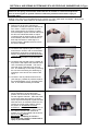
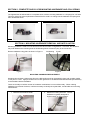
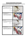
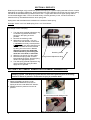
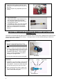
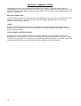
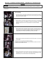
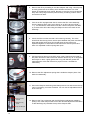
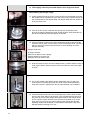
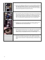
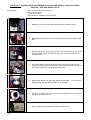
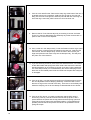
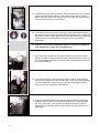
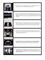
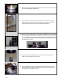
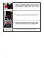
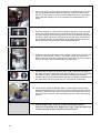
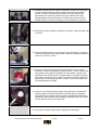
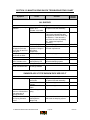
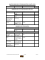
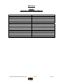
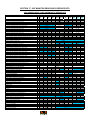
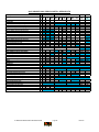
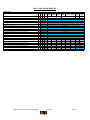
2007 Manitou Rear Shock
Service Guide
REV NC.
1
2007 Manitou Rear Shock Service Manual
Index
Section
Description
1
INTRODUCTION
3
2
SETUP, TUNING, PERIODIC MAINTENANCE
3
3
GLOSSARY
4
4
AIR SPRING SYSTEM AND SPV AIR PRELOAD, SWINGER
AIR
5
5
COMPLETE SHOCK LESS HARDWARE, COIL SPRING
6
6
HARDWARE REMOVAL AND INSTALLATION
6
7
DU BUSHING REMOVAL AND INSTALLATION
7
8
RIDE KITS
8
9
BOTTOMOUT BUMPER REPLACEMENT, SWINGER COIL
8
10
REBOUND ADJUSTER KNOB REMOVAL AND
INSTALLATION, SWINGER COIL
9
11
DAMPING SYSTEM
10
12
DAMPING SYSTEM BLEEDING - SWINGER X3 AIR/ S-TYPE/
RADIUM SHOCKS
11
13
DAMPING SYSTEM BLEEDING - SWINGER X4 AIR/ EVOLVER
ISX4-ISX6/ SPLIT SHOCKS - SHIM AND SPV
15
14
DAMPING SYSTEM BLEEDING – REVOX/ SWINGER X3-X4-X6
COIL/ METAL SHOCKS - SHIM AND SPV
21
15
TROUBLESHOOTING
25
16
TABLE 1: FASTENER TORQUE REQUIREMENTS
27
17
SWINGER REAR SHOCK SERVICE KITS
28
Contact Information
Answer Products Customer Service Department
28209 Ave. Stanford
Valencia, CA 91355
Toll Free: (800) 423-0273
Direct : (661) 257-4411
FAX:
(661) 775-1798
E-mail: [email protected]
[email protected]
Web site: www.answerproducts.com
2
Page
SECTION 1: INTRODUCTION
This manual is intended to guide the user through basic service of Manitou Swinger rear shocks. Service is
supported by the identification of common parts and assemblies that have been assembled into Service Kits.
The purpose of this manual will be to describe conditions that may drive the need for service and to provide
installation instructions for the kits.
Due to the time-consuming nature rear shock service, at this time our primary focus is to offer service kits that
minimize the amount of downtime and labor involved. As the program matures, and we are able to gather
feed back from our customers, we may offer kits to a more detailed level.
Important information is highlighted in this manual by the following notations:
WARNING
Failure to follow WARNING instructions could result in severe injury or death to the
person inspecting or repairing the shock absorber or the shock absorber operator
CAUTION
A CAUTION a caution indicates special precautions that must be taken to avoid damage to
the shock absorber.
NOTE
A NOTE provides key information to make procedures easier or clearer
GENERAL WARNING: Rear shocks by design contain gases and fluids under extreme pressure and
warnings contained in this manual must be observed to reduce the possibility of injury or possible
death. Following these instructions can help you reduce the risk of being injured. Any questions in
regards to the information in this manual should be directed to Answer Products Customer Service at
(661) 257-4411.
WARNING: The Swinger Shock uses compressed air to provide fluid pressure in the
damping system and spring resistance in Air models. BOTH systems must be relieved of
pressure prior to servicing these systems. Failure to relieve air pressure could result in
injury or possible death.
CAUTION: The Swinger Shock uses precision machined aluminum and other soft alloy
components. Using correct tools for assembly is essential to prevent damage.
SECTION 2: SETUP, TUNING, PERIODIC MAINTENANCE
Instructions for shock setup, tuning, and periodic rider maintenance is not covered in detail in this manual.
Please refer to the Manitou Swinger Rear Shock Owner's Manual (PN 042105) for that information. If you did
not receive a manual, you can download one at www.answerproducts.com or contact Answer Products
Customer Service at (661) 257-4411.
3
SECTION 3: GLOSSARY OF TERMS
Air Canister – Can that holds the air spring air in an air shock.
Air Preload Adjuster – Located on the reservoir of SPV shocks. It contains the red Schrader valve for
setting the SPV pressure and a hex fitting for adjusting the air volume (air preload)
Bottom Out – Point at which a shock reaches full compression.
Control Eyelet (C-End) – Eyelet that is on the rebound adjuster end of a shock. The air canister is attached
to this end on air shocks and the spring retention collar is attached to this end on coil shocks.
Damper Eyelet (D-End) - Eyelet that is on the damper body end of a shock. On SPV shocks, this is the end
that contains the SPV valve and reservoir if applicable.
Damper Body – Section of shock that contains the damping system
Damper Piston – Piston in that controls the flow of oil during compression and rebound.
Damper Shaft – Shaft attached to the damper piston that connects the two moving sections (damping system
and control eyelet) of the shock together.
Damping System - Controls compression and rebound rate (speed). The system also provides the peddling
platform unique to shocks with the SPV technology.
DU Bushing – Teflon guide bushing pressed into the eyelets. Mounting hardware is inserted into the DU
bushings and rotates within the bushing as need by the suspension design.
Eyelet – Found on each end of the shock, it is where the DU bushing and mounting hardware are and
provides the connection between the shock and bicycle.
Internal Floating Piston (IFP) - A floating piston that separates damping oil from the SPV air chamber or
reservoir.
Mounting Hardware – Spacers that allow shocks to be mounted into the wide variety of suspension designs.
Schrader, Air – Black in color, it is the valve for pressurizing the air canister in an air shock
Schrader SPV - Red in color, it is the valve for pressurizing the SPV system.
Seals: O-Rings - Black synthetic rubber with a round cross section. Primarily used for fluid
sealing.
Seals: Quad Seals - : Black synthetic rubber with an “X” cross section, primarily used for sealing air.
Seals: Wipers – Teflon ring, used for keeping debris out of quad seals, guiding the damper piston, and
providing support.
Top Out – Point at which a shock returns to its full extension.
4
SECTION 4: AIR SPRING SYSTEM AND SPV AIR PRELOAD, SWINGER AIR, S-Type
WARNING: The Swinger Air uses compressed air to provide resistance to compression in
place of a coil spring. You must be certain that the air canister is relieved of all pressure
prior to servicing the air system. Failure to relieve air pressure could result in injury or
possible death.
Sealing of the shock is accomplished through a series of o-rings, quad seals, and wipers. When the air
canister is removed, these seals can be replaced from Seal Kit C.
1. Failure of an air shock to maintain air
pressure is usually the result of defective or
worn seals. If there is suspicion of an air
leak, pressurize the air canister to 150psi
from the adjuster eyelet Schrader Valve and
the SPV Air Preload Schrader to 100psi.
Locate the leak by spraying the air canister
and Schrader joints with a mild solution of
dish soap and water or submerge in a
bucket of water. Bubbles will form in from
the area of leakage.
2. For leaks at the adjuster eyelet or damper
end of the air canister, refer to the detailed
disassembly instructions contained in the
section on DAMPING SYSTEM BLEEDING
- Swinger Air. This will guide you on how to
replace the applicable o-rings and seals.
3. For leaks at the Schrader valves, release all
air pressure and replace the Schrader valve
core or assembly as needed. The core is
removed using a standard core removal
tool. The assembly is removed by removing
the core and unscrewing the assembly by
inserting a 3mm hex into the center of the
valve.
4. For leaks in the air preload reservoir area
(4W Swinger), release all pressure replace
the preload adjuster o-ring, Schrader valve
core, or Schrader assembly as needed.
5. If when you pressurize the air canister the
shock collapses to its shortest travel
position, the shock has an air piston leak
into the negative chamber. Place the shock
in the shock tester and extend it to its full
travel. Depress the adjuster eyelet Schrader
while the shock is extended under load. If it
remains in the full travel position, refer to
the section on DAMPING SYSTEM
BLEEDING - Swinger Air for instructions on
servicing the air canister and piston seals.
6. If the shock returns to the short travel
position, it is not serviceable and the entire
shock must be replaced.
WARNING: Attempting to service a
shock with this condition could result in
injury or possible death.
5
Adjuster Eyelet
SPV Air Preload
(Air Spring)Schrader
SECTION 5: COMPLETE SHOCK LESS MOUNTING HARDWARE AND COIL SPRING
The highest-level kit offered will be a complete shock, without mounting hardware or coil springs for coil forks.
This kit is offered as a fast replacement where all that is need is to change out the hardware and spring and
then reinstall the shock.
Swinger Air – Less Mounting Hardware
Swinger Coil – Less Mounting Hardware
and Coil
SECTION 6: MOUNTING HARDWARE REMOVAL AND INSTALLATION
Mounting hardware is used to mount shocks to the various frame configurations. Over time, the hardware
may wear between the mounting bolts or DU Bushing which will result in play in the connection.
Remove hardware using pliers as shown in Figure 1
DU Bushing
Eyelet
.
Figure 1
Figure 2
MOUNTING HARDWARE REPLACEMENT
Hardware should have a slight press fit into the DU bushing and can be tapped in place with a rubber mallet
or soft jaws in a vise. Apply a small amount of thick grease such as Motorex Bike Grease 2000 (PN 85-0033)
to the hardware before installation.
There are virtually an infinite number of hardware combinations in use on bikes today. When ordering
hardware from Answer Products, It will be necessary to identify the eyelet width, overall width and mounting
hole diameter.
1. Measure the hardware width.
6
2. Measure mounting hole size. Current
hardware is typically designed to
accept a 6mm or 8mm fastener.
SECTION 7: DU BUSHING REMOVAL AND INSTALLATION
DU bushings are press fit into the shock eyelets at each end of the shock. The hardware fits into the bushings
and will rotate slightly within the bushing during suspension compression. DU Bushings, like hardware, may
wear over time. Removal and installation is accomplished using tool PN 85-6075.
REMOVAL
1. Remove hardware from the shock.
2. Insert unthreaded end of punch into the
removal tool first and screw in about half a
turn.
Punch
3. Clamp removal tool in vise.
4. Insert eyelet into tool.
5. Use 6mm hex wrench to screw in punch,
making sure that it is centered on the
bushing. This will press out the bushing.
INSTALLATION
1. Place a bushing onto the threaded end of
the punch and into the removal tool; screw
in about half a turn.
Bushing
2. Clamp removal tool in vise.
3. Insert eyelet into tool.
4. Use 6mm hex wrench to screw in punch,
making sure that it is centered on the
bushing and that the bushing is centered to
the eyelet. This will press in the bushing.
7
SECTION 8: RIDE KITS
Ride kits (Coil Swinger only) consist of a replacement spring of a specific spring rate that is firmer or softer
depending on the rider's preference. Most manufacturers using Swinger Coil shocks vary the stock spring
rate that is the standard offering based on frame size. Larger frame sized have higher spring rates to
accommodate bigger riders. Due to the wide variety of frame geometry in use, it is left to the rider to
determine if they are satisfied with their stock spring rate.
Spring rates and travel/stroke are marked on the outside of each spring.
Example: "300 X 2.75" Is a 300lb spring for a 2.75" Travel Shock
To change out the coil spring:
1. Turn the spring preload adjustment ring
to release any preload and back it
away from the spring as far as
possible.
2. Remove the retaining collar.
3. Slide spring over eyelet. You may
need to turn the rebound control knob
in clockwise to its fully closed position.
NOTE: Model year 2003 Swingers use
a rebound knob that can be removed
by taking out a hex screw. Do not
attempt to remove the 2004-2005
rebound knobs by unscrewing the
3mm hex in the knob, it will break.
4. Slide the new spring over the eyelet.
5. Reinstall the spring collar so that it
butts against the eyelet, and the spring
nests in the appropriate groove.
6. Turn the spring preload adjustment ring
until it contacts the spring and then
apply 2mm of preload.
Retaining Collar
Spring Preload Adjustment Ring
SECTION 9: BOTTOMOUT BUMPER REPLACEMENT, SWINGER COIL
WARNING: The Swinger Shock uses compressed air to provide fluid pressure in the
damping system. The damping system must be relieved of pressure prior to servicing.
Failure to relieve air pressure could result in injury or possible death.
1. Remove hardware as shown under
HARDWARE REMOVAL and remove
Spring as shown under RIDE KIT Section.
2. Release reservoir pressure from the air
preload.
SPV Air Reservoir 3W Swinger Coil
SPV Air Reservoir 4 & 6W Swinger Coil
8
3. Extend and clamp damper shaft in a vise
using 12.7mm (.500) soft jaws, Answer PN
85-5148
4. Remove eyelet using adjustable open-end
wrench.
5. Slip off old bumper.
6. Install new bumper, Larger diameter face
of the bumper should face the eyelet
7. Clean damper shaft threads with alcohol
and apply Blue Loctite.
8. Install damper shaft in vise using soft jaws
as shown above and torque per Table 1.
9. Add air to re-pressurize the air preload
reservoir per instructions in the Owner’s
Manual.
SECTION 10: REBOUND ADJUSTER KNOB REMOVAL AND INSTALLATION,
SWINGER COIL
Instructions in the 2004 Swinger Shock Owners Manual were incorrect when it stated that the rebound knob
had to be removed to replace shock springs. Turning the knob to its full clockwise setting is sufficient to
provide clearance for removal.
Removal
Rebound Knob
1. Remove control eyelet as shown under
Bottom out Bumper Replacement, Swinger
Coil.
2. Remove 1.5mm hex set screw located under
the control eyelet with the set screw pointed
up. Underneath the set screw is a spring
and detent ball bearing. Turn the eyelet
over on a cloth rag and tap the eyelet to
dislodge the spring and ball.
Set Screw
3. Unscrew the rebound knob from the eyelet.
Installation
Set Screw
Spring
1. Installation is in reverse order. Place a small
amount of grease on the ball and rebound
knob detents. Screw in the knob and place
the ball and spring in the set screw hole.
2. Apply a small amount of blue Loctite to the
set screw threads. Screw in the set screw
until it is flush with the eyelet.
Knob Detents
9
Detent Ball
SECTION 11: DAMPING SYSTEM
The damping system controls compression and rebound rate (speed). The system also provides the
peddling platform unique to shocks with the SPV technology. The main conditions requiring service you may
encounter in regards to the damping system are leaks, a suspect SPV, broken rebound adjuster knob, or lose
damper or reservoir body.
SPV VALVE INSPECTION
If you are unable to achieve the pedaling platform after adjusting the shock per the Owner's Manual, you will
need to inspect the SPV. Follow the instructions under the damping bleeding section for the shock in
question in order to inspect the SPV.
LEAKS
If oil is found to be leaking from the shock, the seals and/or o-rings that seal that suspect joint must be
serviced. Once the system has lost oil, the faulty seals must be replaced and the shock bled to restore the
shock to full performance.
LOOSE DAMPER OR RESEVOIR BODY
All Swinger service can be performed without removing the damper or reservoir bodies where they are
threaded into a machined casting. This joint is bonded in place during final assembly at the factory. If either
becomes loose during service, remove the body, and thoroughly clean the threads on each part. Apply green
Loctite the threads and use the Answer reservoir clamp PN 85-6037 to tighten the bodies.
10
SECTION 12: DAMPING SYSTEM BLEEDING – SWINGER X3/S-TYPE/RADIUM AIR
SHOCKS
WARNING: The Swinger Shock uses compressed air to provide fluid pressure in the damping system.
The damping system must be relieved of pressure prior to servicing. Failure to relieve air pressure
could result in injury or possible death.
Tools Needed:
-
Disassembling
1. Secure the shock in the vise by clamping the Top Cap eyelet in the jaws of
the vise. Remove the Schrader valve core form the air spring valve to relief
all pressure in the air canister.
2. Remove the Air Can from the shock using a 39mm wrench or an adjustable
wrench if it is an X3, if it is a Radium or S-Type you will need to use a strap
wrench to remove the air can. It will unscrew in a counter-clockwise
direction.
3. Remove MCU bottom out bumper from the Air Can. Thoroughly clean out
the interior of the can and MCU. Replace the glide ring and seals in the end
of the canister. Set aside for reassembly. If you are only solving an air
spring leak you do not have to proceed any further, go to step **
4. Remove the Air pressure and Valve from the HP IFP system. You will need
to use P/N#
A. Remove the cap covering the Schrader assembly.
B. Using the valve adapter and a shock pump release air pressure in the IFP.
C. Remove the Schrader valve core
5. Remove the Damper Cap/ Air Piston Cap from the damper body. Using an
adjustable wrench or 14mm wrench. Pull damper shaft assembly from the
damper body. Pour out the oil that is in the damper body.
11
6. Remove the IFP by threading in the valve adaptor and using a shock pump
to slowly pressurize the chamber which will blow the Piston out of the
bottom of the damper body. NOTE: Be sure to cover the end of the damper
body with a shop rag so that the piston and any remaining oil don't shoot
across the work area.
7. If this is an SPV equipped rear shock, remove the SPV valve assembly
from the damper piston using a pin wrench or an SPV valve tool (P/N ******). You will want to insert the tool into the 3 slots in the piston, DO NOT
try to remove the SPV valve using the Phillips screw in the center of the
assembly.
8. Check the SPV to make sure that it is functioning correctly. The valve
should look like the top picture, with a space between the piston and the top
plate and should spring open and closed when the two pieces are
squeezed together. If it has failed it will look like the second picture and
when it is squeezed it will not spring back open.
9. Pull apart the two pieces of the SPV valve, gently clean both the inside of
the piston and the out side of the shim head to remove any oil or old grease
that maybe on them. Lightly grease the o-ring with Wacker grease and
reassemble the valve and recheck for proper function. Set aside for
reassembly.
10. Remove the SPV Adjustment spring that is inside the damper piston. Set
aside for reassembly.
11. Secure the Damper shaft using shaft clamps and a vice and remove the top
cap by unscrewing it counter-clockwise. You can use an adjustable wrench
to turn the cap.
SPV/Lock-out
Needle
Rebound Adj.
Shaft
Top Out Bumper
12
12. Remove the Top-out bumper and the SPV/lockout adjustment needle by
pulling it out of the damper shaft. Screw the rebound adjustment shaft down
so that the flange is just below the top of the damper shaft.
13. Thoroughly clean all parts and replace all o-rings and seals.
Reassembling the Swinger 3-Way
14. Lightly grease the seal on the IFP. Insert the IFP into the damper body with
the cupped side up (towards the open end of the body). Push the IFP all the
way to the bottom of the damper body. Fill damper body with 5wt. Shock oil
to the top of the bore.
15. If this is an SPV shock, install the SPV spring into the damper piston
through the rebound adjustment shaft. Screw the SPV valve assembly into
the top of the damper piston and tighten to 80 inlbs.
16. Push the Damper cap/Air piston down the damper shaft so that the inside
surface of the air piston is even with the hole in the damper shaft. You don't
want to cover the hole as it will prevent the air from bleeding out of the
damper assembly.
Damper Shaft Hole
Air Piston Surface
When the air piston is in the proper
position relative to the hole your
assembly will look similar to this.
17. Insert the Damper piston in into the damper body. It will be helpful to wrap a
shop rag around the damper body to catch the overflow in the next couple
of steps.
18. As you are installing the damper piston and damper cap, you will have
some air and oil coming up through the center of the rebound adjusting
shaft this is normal. Tighten down the Air Piston/Damper cap to 85inlbs.
19. Push the damper shaft down into the damper body until the shaft extends
from the top of the damper cap 8.75mm. This is measured from the top of
the piston to the top of the flange above the threads on the damper shaft.
This is critical to proper function of the shock but it is better to err on the
short side, if it is too long you will not get full travel. Adjust the rebound
adjusting needle until the flange on the needle is flush with the top of the
damper shaft by screwing it in or out.
13
20. Insert the SPV adjusting needle fully into the rebound adjusting needle until
the o-rings have seated. Screw on the Top Cap as snugly as possible. Fully
extend the damper shaft by pulling up on the Top Cap to the end of the
travel. Reinstall the high pressure Schrader valve into the IFP chamber port
but DO NOT charge the IFP. Remove the Top Cap.
21. Keep the damper shaft pointed straight up and clamp it in the vise with the
clamp shafts. Install bottom out bumper and reinstall the top cap using red
Loctite. Torque the top cap to 85 inlbs. Note: you may need to turn the
Rebound counter clockwise a couple of turns as you are threading the top
cap on as it will thread the adjusting needle in due to the detent plate.
22. Charge the IFP to 125psi using a standard shock pump. Install the small,
threaded metal cover over the Schrader valve. You will need to use
components from the HP IFP tool kit for this.
23. Install the top out bumper into the air can. Side the air can over the damper
body. Thread the top cap into the air can and tighten to approximately
100inlbs. Note: It may be helpful to secure the end of the damper eyelet in
the vise so that you can pull up the air can up to meet the top cap.
24. Reinstall the Schrader core in the air can valve. Charge the air spring to
100psi, check to make sure that there are no air leaks. Check the shock
function for lack of rebound or compression damping and dead spots in the
travel.
14
SECTION 13: INSTRUCTIONS FOR SWINGER X4, EVOLVER 4/6-WAY, AND SPLIT REAR
SHOCKS – SPV AND SHIM STYLES
Tools Needed:
- .9mm, 1.3mm, 6mm Allen wrenches
- 39mm, 10mm, wrench
- 1.3mm Allen wrench
- 39mm wrench or suitable crescent wrench
1. Release air in the main air spring and remove the Schrader valve.
2. Release the air that is in the IFP chamber and remove this Schrader valve
also.
3. Remove the air can using a 39mm wrench or a crescent wrench. Once the
can is free from the top cap slide the can down as far as possible to the
damper eyelet.
4. Secure the damper shaft in the vise using the appropriate shaft clamps.
Unscrew the top cap counterclockwise. After removing the top cap remove
the bottom out bumper and the metal washer also.
5. Remove the damper cap using the special socket (P/N**-****) Pull out the
damper shaft, cap and damper piston as an assembly.
6. Pull firmly on the air can to remove it from the damper body. The air piston
will come off with the air can.
7. Remove the piston and top out bumper from the air can.
15
8. If this is a twin-tube Evolver: Remove the snap ring at the base of the can. It
is easiest to do this by inserting a small pick into the gap on the ring and
lifting one end free of the groove, and then just walk the rest of the ring out.
Once the ring is removed, pull the outer can off of the inner can.
9. Remove the No Tools Volume adjust by unscrewing it counter clockwise.
There is no need to disassembly the assembly any further as there are no
parts to wear in the no tools adjuster.
10. Pour out the oil in the damper body. Cover the Reservoir with a rag to catch
the IFP and any oil which might be trapped to the reservoir. Insert the IFP
removal tool, into the damper body. Cover the hole in the tool with your
finger and press the tool down firmly into the damper body. This will push
the piston out of the reservoir.
11. If you are servicing an ISX-6, remove the red and black knobs, use caution
as the detent balls and springs are VERY small. Next remove the Intrinsic
damping assembly by unscrewing it counter clock-wise. Pull the assembly
out of the damper body. Do not disassembly the Intrinsic damping unit as
there are no serviceable parts inside and several of the parts are easily lost
or damaged.
12. If this is an ISX-4, use the special penta-hex tool (P/N 83-3236) to remove
the non-adjustable Intrinsic damping assembly. As with the ISX-6, other
than the O-rings on the out side of the assy. There are no serviceable parts
inside the damping unit so do not attempt to disassemble the unit further.
13. If this is an SPV shock, you need to make sure that the SPV valve is
functioning correctly. The valve should look like the top picture, with a
space between the piston and the top plate and should spring open and
closed when the two pieces are squeezed together. If it has failed it will
probably look like the second picture and when it is squeezed it will not
spring back open.
16
14. To Remove the SPV valve for service, clamp the shaft in the vise using the
proper size shaft clamps. Using a **mm wrench loosen the clamp bolt.
Remove the bolt, shim stack, piston and the SPV valve. Be sure to keep all
items in the proper order and orientation
15. Pull apart the two pieces of the SPV valve, gently clean both the inside of
the piston and the out side of the shim head to remove any oil or old grease
that maybe on them. Lightly grease the quad seals with Silicone grease and
reassemble the valve and recheck for proper function. Set aside for
reassembly.
16. Inspect air can, pistons and damper body for excessive or abnormal
wear. Replace all o-rings, seals and glide rings.
17. Secure the shock eyelet in a vise with the mounting hole for the intrinsic
damper up. Fill the hole with oil and install the Intrinsic damping control unit.
If it is an adjustable unit for an X6, be sure that the adjusters are turned out
to the lowest settings.
18. Turn the shock body so that the damper body is vertical. Fill the damper
about 3/4 full, using the IFP removal tool push oil thru the Intrinsic damping
unit into the Reservoir. Do this until you no longer see bubbles coming
through the port in the bottom of the reservoir.
19. Install the bleed bowl, and fill the reservoir and bowl with 5wt shock fluid.
Install the IFP by lowering it into the fluid vertically so no air is trapped in
the cavity if the piston. Turn the piston 90 degrees and push it into the
reservoir past the threads. Remove the oil above the piston. Remove the
bleed bowl.
17
20. Make sure that the IFP Positioning Tool is in its shortest position; Screw it
down into the reservoir pushing the IFP into the bore.
21. If you are servicing an Evolver with a twin tube, grease the two o-rings on
the inner can with a small amount of silicone grease. Reinstall the outer can
by sliding it on the inner can, be sure that is slid all the way to the end of the
inner can.
22. Install the snap ring to retail the outer can by pressing it into the groove.
Makes sure that is firmly seated into the groove, you will be able to that it
completely seated as the ends of the snap ring will be almost touching.
23. Insert the air can installation tool into the damper body. Slide the air can
over the tool and on to the damper body. Next install the top out bumper
then remove the Installation tool.
24. Install the air piston into the air can and push it all the way down until it
seats fully on to the top of the damper body. There should be no space
between the top of the damper body and the bottom of the air piston.
25. Reinstall piston, shim stacks and the SPV valve on to the damper shaft,
tighten bolt to 80inlbs. Line the damper cap up so that the inner end of the
cap is lined up with the edge of the bleed hole in the damper shaft. Fill the
damper body with oil.
18
26. Insert the damper piston/shaft assembly into the damper body. Screw down
the top cap and torque to 60-70inlbs.
27. Insert the rebound preload spring and rebound needle into the damper
shaft and then screw on the top cap. Using the top cap fully extend the
damper shaft. Remove the top cap and the rebound needle.
28. Next using a 6mm Allen wrench screw the IFP Positioning tool down to the
line matching the travel/stroke of the shock you are servicing, you want the
line to just disappear below the top of the flange, see the picture below. You
will have oil come out of the damper shaft as you do this. This gives you the
final bleed on the shock.
29. Reinstall the rebound needle, bottom out bumper, and the bottom out
washer. Clean the tread of all oil residue.
30. Clamp the damper shaft in a vise using the 12.5mm shaft blocks. Apply
blue Loctite to the threads of the damper shaft. Screw on the damper cap
and to torque it to 110inlbs. (12 Nm)
19
31. Remove the IFP tool from the reservoir and install the Volume control
assembly. Torque the assembly to 100inlbs (11Nm). Turn the control to the
open position, this is where the indicator is in the number 1 position, this
allows the entire volume control to be pressurized. On Swinger X4 shocks
charge the IFP to 125psi. For the Evolver shocks the SPV version is
charged to 120psi and the shim version to 150psi. The charge pressure is
250psi on the Split shocks.
32. Pull the air can up and screw the top cap down. Clamp the top cap in the
vise and using a 39mm wrench torque the air can to 80 inlbs ( 9Nm)
33. If applicable, install the detent springs, balls and knobs on the Intrinsic
Adjuster. Make sure that the set screw on the high speed compression
knob (black knob) is lined up with the pocket on the adjuster shaft before
tightening it. Next install the red lox speed compression knob.
34. Charge the air spring and check for proper function of the shock.
20
SECTION 14: INSTRUCTIONS FOR REVOX/SWINGER COIL/METAL REAR SHOCKS WITH
SPV OR SHIM DAMPING
Tools Needed:
- .9mm, 1.3mm, 6mm Allen wrenches
- 26mm, 28mm or suitable adjustable wrench
- Manitou Rear Shock Service Tool Kit
1. Turn the Volume adjuster so that it is in position. Release the air in the
IFP chamber and remove the Schrader valve core.
Caution – If you do not have the adjuster in the number 1 position you will not
full discharge the IFP system and risk serious injury if you continue with the
disassembly process.
2. Remove the No Tools Volume adjust by unscrewing it counter clockwise.
There is no need to disassembly the assembly any further as there are no
parts to wear in the no tools adjuster.
3. Make sure that the shock is full extended. Clamp the shock in a vise by the
damper eyelet. Using a 28mm or an adjustable wrench, remove the damper
cap and shaft from the shock by turning it counter-clockwise. Drain out as
much fluid as possible after pulling the damper assembly out of the shock.
4. Pour out the oil in the damper body. Cover the Reservoir with a rag to catch
the IFP and any oil which might be trapped to the reservoir. Insert the IFP
removal tool, into the damper body. Cover the hole in the tool with your
finger and press the tool down firmly into the damper body. This will push
the piston out of the reservoir.
5. If you are servicing an ISX-6, remove the red and black knobs, use caution
as the detent balls and springs are VERY small. Next remove the Intrinsic
damping assembly by unscrewing it counter clock-wise. Pull the assembly
out of the damper body. Do not disassembly the Intrinsic damping unit as
there are no serviceable parts inside and several of the parts are easily lost
or damaged.
21
6. If this is an ISX-4, use the special penta-hex tool (P/N 83-3236) to remove
the non-adjustable Intrinsic damping assembly. As with the ISX-6, other
than the O-rings on the out side of the assembly there are no serviceable
parts inside the damping unit so do not attempt to disassemble the unit
further
7. If you are working on a shim style shock skip to step #10, if this is an SPV
shock, you need to make sure that the SPV valve is functioning correctly.
The valve should look like the top picture, with a space between the piston
and the top plate and should spring open and closed when the two pieces
are squeezed together. If it has failed it will probably look like the second
picture and when it is squeezed it will not spring back open.
8. To Remove the SPV valve for service, clamp the shaft in the vise using the
proper size shaft clamps. Using a **mm wrench loosen the clamp bolt.
Remove the bolt, shim stack, piston and the SPV valve. Be sure to keep all
items in the proper order and orientation for reassembly.
9. Pull apart the two pieces of the SPV valve, gently clean both the inside of
the piston and the out side of the shim head to remove any oil or old grease
that maybe on them. Check the quad seals for damage and replace if
needed. Lightly grease the quad seals with Silicone grease and reassemble
the valve and recheck for proper function. Set aside for reassembly.
10. For all shocks, clamp the damper shaft in a vise using the shaft clamps.
Using an adjustable wrench remove the control eyelet by turning it counterclockwise. Take care that you do not apply force to the rebound knows as
the can be bent or broken. After removing the eyelet, remove the rebound
needle.
11. Inspect damper body, reservoir, pistons and damper shaft for
excessive or abnormal wear. Replace all o-rings, seals and glide rings
and any other parts that are showing excessive wear.
22
12. Secure the shock eyelet in a vise with the mounting hole for the intrinsic
damper up. Fill the hole with oil and install the Intrinsic damping control unit.
If it is an adjustable unit for an X6, be sure that the adjusters are turned out
to the lowest settings
13. Turn the shock body so that the damper body is vertical. Fill the damper
about 3/4 full, using the IFP removal tool push oil thru the Intrinsic damping
unit into the Reservoir. Do this until you no longer see bubbles coming
through the port in the bottom of the reservoir.
14. Install the bleed bowl, and fill the reservoir and bowl with 5wt shock fluid.
Install the IFP by lowering it into the fluid vertically so no air is trapped in
the cavity if the piston. Turn the piston 90 degrees and push it into the
reservoir past the threads. Remove the oil above the piston. Remove the
bleed bowl.
15. Make sure that the IFP Positioning Tool is in its shortest position; Screw it
down into the reservoir pushing the IFP into the bore. If you are rebuilding a
Revox shock, be sure that you fit the IFP extension (P/N **-****) to the
Positioning tool before installing it into the reservoir.
16. Reinstall piston, shim stacks and the SPV valve on to the damper shaft,
tighten bolt to 80inlbs if it was removed earlier. Line the damper cap up so
that the inner end of the cap is lined up with the edge of the bleed hole in
the damper shaft. Fill the damper body with oil.
17. Insert the damper piston/shaft assembly into the damper body. Screw down
the top cap and torque to 60-70inlbs. Make sure that the shaft isn’t moving
out as you do this.
23
18. Extend the damper shaft, it might be necessary to screw on the top cap so
you have something to grip to pull it out with. Next using a 6mm Allen
wrench, screw the IFP Positioning tool down to the line matching the
travel/stroke of the shock you are servicing, you want the line to just
disappear below the top of the flange. You will have oil come out of the
damper shaft as you do this. This gives you the final bleed on the shock.
19. Reinstall the rebound needle, and bottom out bumper. Clean the tread of all
oil residue.
20. Clamp the damper shaft in a vise using the 12mm shaft blocks. Apply blue
Loctite to the threads of the damper shaft. Screw on the damper cap and to
torque it to 110inlbs. (12 Nm)
21. Remove the IFP tool from the reservoir and install the Volume control
assembly. Torque the assembly to 100inlbs (11Nm). Turn the control to the
open position, this is where the indicator is in the number 1 position, this
allows the entire volume control to be pressurized. On Swinger and Revox
SPV shocks, charge the IFP to 120psi. For the shim versions of the Revox
and Swinger coil the charge pressure is 150psi. For the metal shocks the
IFP charge pressure is 250psi.
22. If this is an X6, install the detent springs, balls and knobs on the Intrinsic
Adjuster. Make sure that the set screw on the high speed compression
knob (black knob) is lined up with the pocket on the adjuster shaft before
tightening it. Next install the red low-speed compression knob, use a small
amount of blue Loctite on the fixing screw.
23. Test shock for proper rebound and compression characteristic.
'07 MANITOU REAR SHOCK SERVICE GUIDE
Page 24
REV NC
SECTION 15: MANITOU REAR SHOCK TROUBLESHOOTING CHART
Symptom
Cause
Solution
Service
Section
ALL SHOCKS
Cannot set pedaling
platform
SPV Schrader valve
snapped off at base
on 3 Way Air and Coil
Swingers.
Adjusting rebound
knob has no effect.
Oil comes out of the
SPV Schrader valve
Play in shock eyelets
when mounted in bike
Damping System
Air loss from SPV
Tighten or replace Schrader core
system: SPV
or replace Schrader assembly.
Schrader valve leaks
SPV Valve failure
Close rebound knob (clockwise).
If the shock rebounds fast after
compression, the SPV valve may
be defective. If the rebound is
very slow, the valve is probably
OK. Inspect and replace if
necessary
Air in damping system Bleed damping system
Interference with
Replace. Confirm clearance after
suspension linkage or Schrader replacement
other frame
components
Air in damping system Bleed damping system
Damping oil has
Replace o-ring on the IFP and
leaked past the IFP
bleed the damping system
Mounting Hardware
Worn DU bushing or
Replace
mounting hardware
4
12 - 15
12 - 15
4
12 - 15
12 - 15
6 -7
SWINGER AIR/ S-TYPE/ RADIUM/ EVOLVER/ SPLIT
Air loss from air spring
Air shock does not
return to full travel but
has adequate air
spring pressure
Oil comes out of the
Air Spring Schrader
valve
Air Spring
Air spring Schrader
Tighten or replace Schrader core
valve leaks
or replace Schrader assembly.
Seal failure on Air
Replace seal(s)
Canister
Seal failure on Air
Replace seal(s)
Piston
Failure of negative
Replace air canister and seals
spring
Damping oil has
leaked past the
damper cap
'07 MANITOU REAR SHOCK SERVICE GUIDE
Replace seals on the damper cap
and bleed the damping system
Page 25
4
4
4
4
14 - 15
REV NC
MANITOU REAR SHOCK TROUBLESHOOTING CHART (CONT.)
Symptom
Cause
Solution
Service
Section
SWINGER AIR/ S-TYPE/ RADIUM/ EVOLVER/ SPLIT
Hard Bottomout
Hard top out
Air Volume adjuster
on 4 Way Swinger
has no affect on
damping rate.
Oil leak at base of air
canister
Air Spring
Air spring pressure
Increase air canister air pressure
too low
Worn bottomout
Replace bottomout bumper
bumper
Failure of negative
Replace air canister and seals
spring
Damaged adjuster
Replace o-ring
piston o-ring
Worn or damaged
seals allowing oil to
escape from damper
chamber
Replace seals and bleed damping
system
4
14 - 15
4
15
4
SWINGER COIL/ REVOX/ METAL
Hard bottomout
Hard top out
Oil leak at high and
low speed
compression adjuster
screws
Oil leak at damper
shaft
Broken rebound knob
on coil shocks
Air Volume adjuster
on 4 or 6 Way
Swinger has no affect
on damping rate.
Spring System
Spring rate too low
Replace with firmer spring
Worn bottomout
Replace bottomout bumper
bumper
Air in damping system Bleed damping system
Damping System
Worn or damaged
Replace adjuster needle and/or oadjuster needles
rings
and/or o-ring allowing
oil to escape
Worn or damaged
Replace seals and bleed damping
seals allowing oil to
system
escape from damper
chamber
User attempted to
Replace rebound knob
remove knob during
spring replacement
Damaged adjuster
Replace o-ring
piston o-ring
'07 MANITOU REAR SHOCK SERVICE GUIDE
Page 26
8
9
12 - 13
13
12 - 13
11
13
REV NC
SECTION 16
TABLE 1
FASTENER TORQUE REQUIREMENTS
Feature
Torque
Swinger Air/ S-Type/ Radium/ Evolver
Air Canister
Air Piston to Damper
Air Volume Adjuster, Swinger Air 4 Way
Damper Piston Bolt
Damper Shaft to Control Eyelet
Schrader Valve Stem
15 – 24KgCm (13 – 21inlbs)
70 - 90 KgCm ( 61 to 78 inlbs)
70 - 90 KgCm ( 61 to 78 inlbs)
70 - 90 KgCm ( 61 to 78 inlbs)
70 - 90 KgCm ( 61 to 78 inlbs)
5 – 10 KgCm ( 4 to 9 inlbs)
Swinger Coil/ Revox/ Metal
Air Volume Adjuster, Swinger Coil 4&6 Way
Damper Cap
Damper Piston Bolt
Damper Shaft to Control Eyelet
Schrader Valve Stem
70 - 90 KgCm ( 61 to 78 inlbs)
70 - 90 KgCm ( 61 to 78 inlbs)
70 - 90 KgCm ( 61 to 78 inlbs)
90 - 110 KgCm ( 78 to 95 inlbs)
5 – 10 KgCm ( 4 to 9 inlbs)
'07 MANITOU REAR SHOCK SERVICE GUIDE
Page 27
REV NC
SECTION 17: 2007 MANITOU REAR SHOCK SERVICE KITS
2007 SWINGER AIR/ S-TYPE/ RADIUM/ SPLIT SERVICE KITS
Kit Description
Kit
Radium
R
Split
RL
RP
Swinger Air
RPA
Shim
Air Canister
Air Canister, 152mm Eye to Eye, 32mm Travel
Air Canister, 165mm Eye to Eye, 38mm Travel
Air Canister, 178mm Eye to Eye, 40mm Travel
Air Canister, 190/200/210mm Eye to Eye, 50mm Travel
Air Canister, 200mm Eye to Eye, 56mm Travel
Air Canister, 215mm Eye to Eye, 63mm Travel
Air Canister, 222mm Eye to Eye, 70mm Travel
Air Canister, 230mm Eye to Eye, 70mm Travel
Air Canister, 240mm Eye to Eye, 76mm Travel
Air Canister, 320mm Eye to Eye, 63mm Travel LRS
Schrader Valves
Radium, Radium R, & Swinger Air Canister Schrader Valve Assy - Black
Radium RL Air Canister Schrader Valve Assy; inc O-Ring, Black
Swinger SPV Schrader Valve Assy; inc O-Ring, Red
90 Degree Schrader Air Valve, Black
360 Degree SPV Schrader Air Valve, Red
360 Degree Air Can Schrader Air Valve, Black
Complete Shock Body, No Hardware or Spring
Shock, No Hardware, 152mm Eye to Eye, 32mm Travel
Shock, No Hardware, 165mm Eye to Eye, 38mm Travel
Shock, No Hardware, 190mm Eye to Eye, 50mm Travel
Shock, No Hardware, 200mm Eye to Eye, 50mm Travel
Shock, No Hardware, 200mm Eye to Eye, 57mm Travel
Shock, No Hardware, 215mm Eye to Eye, 63mm Travel
Shock, No Hardware, 222mm Eye to Eye, 70mm Travel
Shock, No Hardware, 230mm Eye to Eye, 70mm Travel
Shock, No Hardware, 240mm Eye to Eye, 76mm Travel
Shock, No Hardware, 320mm Eye to Eye, 63mm Travel/w hiemjoint LRS
Trunion - 63mm Wide, 44mm Travel Ref OE PN 85-17181
Trunion - 61mm Wide, 44mm Travel Ref OE PN 85-17182
Trunion - 61mm Wide, 44mm Travel Ref OE PN 85-17183
Radium, Metel Shock IFP Chamber Refill Plug
Rebound Knob
Swinger 4/6W Reservoir Air Volume Adjuster
Swinger 4/6W Reservoir No-Tools Volume Adjuster
Comp Speed Adjuster Knob/Needles Kit
Comp Speed Adjuster Knob/Needles Kit O-Rings
SPV Valve
H/L Compression Assembly
Remote Lockout Cable
Remote Lockout Conversion Kit (Updated Cable Spool)
Remote Ready Conversion Kit (Non Warranty)
Seal Kit
Swinger 3W LRS Seal Kit
Swinger 6W Remote Reservoir Seal Kit
Heim Joint Mounting Hardware - Swinger 3W LRS
DU Bushing Kit
DU Bushing Kit
Heim Joint - Swinger 3W LRS
Sticker Kit
Tools
Tool for adjusting Swinger Air Reservoir Volume
Tool for locating Swinger IFP during bleed process
DU Bushing Tool
Guide for Air Canister Seals over Damper Body
Plunger for Removal of IFP Piston, Swinger Air
Tool for Bleeding Swinger Air & Coil Reservoir Shocks
Fixture to Hold and Compress Shocks
Fixture for Clamping 10mm Damper Shaft
Fixture for Clamping 12.7mm Damper Shaft
Shock Pump - Air Canister
Shock Pump - SPV Reservoir
Fixture for Clamping Reservoir and Damber Body, Swinger Air and Coil
High Pressure IFP Tool set
A
A
A
A
A
A
A
A
A
A
83-2221
83-2222
83-2224
83-2227
83-2228
83-2229
83-2230
SRL
83-2999
83-3000
83-3001
83-3003
83-3004
SR SPV
ISX-4
Shim
83-2698
83-2699
83-2700
83-2702
Evolver
ISX-4
SPV
SPV
ISX-6
Shim
83-3005
83-3006
83-3007
83-3008
83-3009
83-3010
83-2271
A 83-2231
A
83-2232
A
A
83-2240
A
A
B
B
B
B
B
B
B
B
B
Air X3
Air X4
SPV
S-Type
85-6715
85-6716
85-6717
85-6718
83-2231
83-2233
83-2240
83-2241 83-2243
83-3242
85-6719
85-6720 85-6723 85-6728
85-6721 85-6724 85-6729
85-6722 85-6725 85-6730
TBD
TBD
85-6726 85-6731
85-6727 85-6732
85-7100
85-7101
85-7102
85-7103
85-7167
83-2241
85-6735
85-6736
85-7104 85-6737
85-7105 85-6738
85-7168
83-2242
83-2243
83-3242
85-6740
85-6741
85-6742 85-7106 85-7160
85-6743 85-7107 85-7161
85-7108 85-7162
85-7109 85-7163
85-7110 85-7164
85-7111 85-7165
85-7112 85-7166
85-7113
85-7114
85-7115
85-7116
85-7117
85-7118
85-7119
85-17134
TBD
TBD
TBD
B
B
B
B
B
B
B
B
C
C
C
D
E
E
E
F
H
H
H
H
H
H
H
H
H
H
H
H
H
H
'07 MANITOU REAR SHOCK SERVICE GUIDE
83-2703
83-3013
83-3013
83-2239
066299
83-2526
83-2974
83-3142
83-2708
83-3013
83-3013
85-4493
85-4485
066299
83-3015
83-3013
85-4485
83-2706
83-2526
83-2974
83-3240
83-2709
83-2708
85-6277
83-2879
066299 066299
83-3016
83-2878
83-3014
83-2707
83-2710
83-2273
85-6105
83-2244 83-2246
83-2711
83-2272
83-2250
83-2251
TBD
85-4406
85-3007
85-6107
85-6075
85-4430
85-4413
85-4414
85-3008
85-4406
85-4162
85-4162
85-4430
TBD
83-2252 83-2253 83-2254
85-3007
85-6107
85-4414
85-5148
85-4163
85-6031
83-2694
Page 28
83-2694
REV NC
2007 SWINGER COIL/ RREVOX/ METAL SERVICE KITS
Kit Description
Kit
Metel
R
Schrader Valves
Swinger SPV Schrader Valve Assy; inc O-Ring, Red
360 Degree SPV Schrader Air Valve, Red
Complete Shock Body, No Hardware or Spring
Shock, No Hardware, 165mmEye to Eye, 38mmTravel
Shock, No Hardware, 190mmEye to Eye, 50mmTravel
Shock, No Hardware, 200mmEye to Eye, 50mmTravel
Shock, No Hardware, 215mmEye to Eye, 63mmTravel
Shock, No Hardware, 222mmEye to Eye, 70mmTravel
Shock, No Hardware, 230mmEye to Eye, 70mmTravel
Shock, No Hardware, 240mmEye to Eye, 76mmTravel
Shock, No Hardware, 267mmEye to Eye, 90mmTravel
Swinger 6WRemote Reservoir Hose Kit
Swinger 6WRemote Reservoir Hose Fitting Kit
Radium, Metel Shock IFP Chamber Refill Plug
Rebound Knob
Swinger 4/6WReservoir Air Volume Adjuster
Swinger 4/6WReservoir No-Tools Volume Adjuster
Comp Speed Adjuster Knob/Needles Kit
Comp Speed Adjuster Knob/Needles Kit O-Rings
SPV Valve
H/L Compression Assembly
Seal Kit
Swinger 6WRemote Reservoir Seal Kit
DU Bushing Kit
DU Bushing Kit
Sticker Kit
Spring Retention Collar
Tools
Tool for adjusting Swinger Air Reservoir Volume
Tool for locating Swinger IFP during bleed process
DU Bushing Tool
Plunger for Removal of IFP Piston , Swinger Coil
Tool for Bleeding Swinger Air & Coil Reservoir Shocks
Fixture to Hold and Compress Shocks
Fixture for Clamping 12.7mmDamper Shaft
Fixture for Clamping 14mmDamper Shaft
Shock Pump - SPV Reservoir
Fixture for Clamping Reservoir and Damber Body, Swinger Air and Coil
High Pressure IFP Tool set
RP
RPA
A
A
B
B
B
B
B
B
B
B
B
B
B
B
B
B
B
B
B
B
C
C
E
E
F
G
H
H
H
H
H
H
H
H
H
H
H
H
83-2242
85-6745
85-6746
85-6747
85-6748
85-6755
85-6756
85-6757
85-6758
85-6759
85-6750 85-6760
85-6751 85-6761
85-6765
85-6766
85-6767
85-6768
85-6769
85-6770
85-6771
85-6772
Revox
Revox
ISX
Shim
ISX
SPV
85-7155
85-7156
85-7157
85-7158
85-6775
85-6776
85-6777
85-6778
83-3012
83-2876
83-2876
85-4485
83-2879
066299 066299
85-6098
83-3014 83-2878
83-2707
83-2710
85-4485
83-2879
85-4485
83-2879
83-2878
83-2881
83-2880
83-2878
83-2881
Swinger Coil
Coil X3- Coil X4- Coil X6- Coil X3- Coil X4- Coil X6SFS
SFS
SFS
SPV
SPV
SPV
Shim
SPV
83-2243
85-7120
85-7121
85-7122
85-7123
85-7130
85-7131
85-7132
85-7133
85-7134
85-7124 85-7135
85-7125 85-7136
85-7145
85-7146
85-7147
85-7148
85-7149
85-7150
85-7151
85-6280
85-6281
83-2242
85-7170
85-7171
85-7172
85-7173
85-7176
85-7177
85-7178
85-7179
85-7180
85-7174 85-7181
85-7175 85-7182
83-3012
83-3012
85-4493
83-2239
066299 066299
85-7183
85-7184
85-7185
85-7186
85-7187
85-7188
85-7189
85-6280
85-6281
85-4493
85-4485
83-2879
066299 066299
83-3014 83-2878
83-2707
83-2710
83-2707
83-2243
85-6105
83-2247 83-2248 83-2249 83-2252 83-2253 83-2254 83-2252 83-2253 83-2254
85-5437
85-5437
'07 MANITOU REAR SHOCK SERVICE GUIDE
85-5148
85-3007
85-6107
85-3007
85-6107
85-4414
85-4423
85-4414
85-5148
83-2882
TBD
TBD
TBD
TBD
85-5148
85-4163
85-6031
83-2694
Page 29
REV NC
2007 COIL SPRING RIDE KITS
K it D e s c rip tio n
K it
M e te l
R RP
R id e K its
S p rin g fo r
S p rin g fo r
S p rin g fo r
S p rin g fo r
S p rin g fo r
S p rin g fo r
S p rin g fo r
S p rin g fo r
S p rin g fo r
S p rin g fo r
S p rin g fo r
C o il
C o il
C o il
C o il
C o il
C o il
C o il
C o il
C o il
C o il
C o il
S hock
S hock
S hock
S hock
S hock
S hock
S hock
S hock
S hock
S hock
S hock
165
165
165
165
165
165
165
165
165
165
165
X
X
X
X
X
X
X
X
X
X
X
38
38
38
38
38
38
38
38
38
38
38
S p rin g
S p rin g
S p rin g
S p rin g
S p rin g
S p rin g
S p rin g
S p rin g
S p rin g
S p rin g
S p rin g
fo r
fo r
fo r
fo r
fo r
fo r
fo r
fo r
fo r
fo r
fo r
C o il
C o il
C o il
C o il
C o il
C o il
C o il
C o il
C o il
C o il
C o il
S hock
S hock
S hock
S hock
S hock
S hock
S hock
S hock
S hock
S hock
S hock
190
190
190
190
190
190
190
190
190
190
190
or
or
or
or
or
or
or
or
or
or
or
200
200
200
200
200
200
200
200
200
200
200
S p rin g
S p rin g
S p rin g
S p rin g
S p rin g
S p rin g
S p rin g
S p rin g
S p rin g
S p rin g
S p rin g
fo r
fo r
fo r
fo r
fo r
fo r
fo r
fo r
fo r
fo r
fo r
C o il
C o il
C o il
C o il
C o il
C o il
C o il
C o il
C o il
C o il
C o il
S hock
S hock
S hock
S hock
S hock
S hock
S hock
S hock
S hock
S hock
S hock
200
200
200
200
200
200
200
200
200
200
200
x
x
x
x
x
x
x
x
x
x
x
57m m
57m m
57m m
57m m
57m m
57m m
57m m
57m m
57m m
57m m
57m m
S p rin g
S p rin g
S p rin g
S p rin g
S p rin g
S p rin g
S p rin g
S p rin g
S p rin g
S p rin g
S p rin g
fo r
fo r
fo r
fo r
fo r
fo r
fo r
fo r
fo r
fo r
fo r
C o il
C o il
C o il
C o il
C o il
C o il
C o il
C o il
C o il
C o il
C o il
S hock
S hock
S hock
S hock
S hock
S hock
S hock
S hock
S hock
S hock
S hock
215
215
215
215
215
215
215
215
215
215
215
X
X
X
X
X
X
X
X
X
X
X
63
63
63
63
63
63
63
63
63
63
63
(8 .5 "
(8 .5 "
(8 .5 "
(8 .5 "
(8 .5 "
(8 .5 "
(8 .5 "
(8 .5 "
(8 .5 "
(8 .5 "
(8 .5 "
S p rin g
S p rin g
S p rin g
S p rin g
S p rin g
S p rin g
fo r
fo r
fo r
fo r
fo r
fo r
C o il
C o il
C o il
C o il
C o il
C o il
S hock
S hock
S hock
S hock
S hock
S hock
222
222
222
222
222
222
X
X
X
X
X
X
70
70
70
70
70
70
(8 .7 5 "
(8 .7 5 "
(8 .7 5 "
(8 .7 5 "
(8 .7 5 "
(8 .7 5 "
or
or
or
or
or
or
9 .0 "
9 .0 "
9 .0 "
9 .0 "
9 .0 "
9 .0 "
X
X
X
X
X
X
2 .7 5 "),
2 .7 5 "),
2 .7 5 "),
2 .7 5 "),
2 .7 5 "),
2 .7 5 "),
R a te :
R a te :
R a te :
R a te :
R a te :
R a te :
S p rin g
S p rin g
S p rin g
S p rin g
S p rin g
S p rin g
S p rin g
S p rin g
S p rin g
S p rin g
S p rin g
fo r
fo r
fo r
fo r
fo r
fo r
fo r
fo r
fo r
fo r
fo r
C o il
C o il
C o il
C o il
C o il
C o il
C o il
C o il
C o il
C o il
C o il
S hock
S hock
S hock
S hock
S hock
S hock
S hock
S hock
S hock
S hock
S hock
230
230
230
230
230
230
230
230
230
230
230
X
X
X
X
X
X
X
X
X
X
X
70
70
70
70
70
70
70
70
70
70
70
(8 .7 5 "
(8 .7 5 "
(8 .7 5 "
(8 .7 5 "
(8 .7 5 "
(8 .7 5 "
(8 .7 5 "
(8 .7 5 "
(8 .7 5 "
(8 .7 5 "
(8 .7 5 "
or
or
or
or
or
or
or
or
or
or
or
9 .0 "
9 .0 "
9 .0 "
9 .0 "
9 .0 "
9 .0 "
9 .0 "
9 .0 "
9 .0 "
9 .0 "
9 .0 "
X
X
X
X
X
X
X
X
X
X
X
2 .7 5 "),
2 .7 5 "),
2 .7 5 "),
2 .7 5 "),
2 .7 5 "),
2 .7 5 "),
2 .7 5 "),
2 .7 5 "),
2 .7 5 "),
2 .7 5 "),
2 .7 5 "),
R a te :
R a te :
R a te :
R a te :
R a te :
R a te :
R a te :
R a te :
R a te :
R a te :
R a te :
S p rin g
S p rin g
S p rin g
S p rin g
S p rin g
S p rin g
S p rin g
S p rin g
S p rin g
fo r
fo r
fo r
fo r
fo r
fo r
fo r
fo r
fo r
C o il
C o il
C o il
C o il
C o il
C o il
C o il
C o il
C o il
S hock
S hock
S hock
S hock
S hock
S hock
S hock
S hock
S hock
240
240
240
240
240
240
240
240
240
X
X
X
X
X
X
X
X
X
76
76
76
76
76
76
76
76
76
(9 .5 "
(9 .5 "
(9 .5 "
(9 .5 "
(9 .5 "
(9 .5 "
(9 .5 "
(9 .5 "
(9 .5 "
(6 .5 "
(6 .5 "
(6 .5 "
(6 .5 "
(6 .5 "
(6 .5 "
(6 .5 "
(6 .5 "
(6 .5 "
(6 .5 "
(6 .5 "
X
X
X
X
X
X
X
X
X
X
X
X
X
X
X
X
X
X
X
X
X
X
50
50
50
50
50
50
50
50
50
50
50
1 .5 "),
1 .5 "),
1 .5 "),
1 .5 "),
1 .5 "),
1 .5 "),
1 .5 "),
1 .5 "),
1 .5 "),
1 .5 "),
1 .5 "),
(7 .5 "
(7 .5 "
(7 .5 "
(7 .5 "
(7 .5 "
(7 .5 "
(7 .5 "
(7 .5 "
(7 .5 "
(7 .5 "
(7 .5 "
(7 .8 7 5 "
(7 .8 7 5 "
(7 .8 7 5 "
(7 .8 7 5 "
(7 .8 7 5 "
(7 .8 7 5 "
(7 .8 7 5 "
(7 .8 7 5 "
(7 .8 7 5 "
(7 .8 7 5 "
(7 .8 7 5 "
X
X
X
X
X
X
X
X
X
X
X
X
X
X
X
X
X
X
X
X
R a te :
R a te :
R a te :
R a te :
R a te :
R a te :
R a te :
R a te :
R a te :
R a te :
R a te :
or
or
or
or
or
or
or
or
or
or
or
X
X
X
X
X
X
X
X
X
X
X
2 .5 "),
2 .5 "),
2 .5 "),
2 .5 "),
2 .5 "),
2 .5 "),
2 .5 "),
2 .5 "),
2 .5 "),
2 .5 "),
2 .5 "),
3 .0 "),
3 .0 "),
3 .0 "),
3 .0 "),
3 .0 "),
3 .0 "),
3 .0 "),
3 .0 "),
3 .0 "),
2 .2 5 "),
2 .2 5 "),
2 .2 5 "),
2 .2 5 "),
2 .2 5 "),
2 .2 5 "),
2 .2 5 "),
2 .2 5 "),
2 .2 5 "),
2 .2 5 "),
2 .2 5 "),
R a te :
R a te :
R a te :
R a te :
R a te :
R a te :
R a te :
R a te :
R a te :
R a te :
R a te :
R a te :
R a te :
R a te :
R a te :
R a te :
R a te :
R a te :
R a te :
R a te :
X
X
X
X
X
X
X
X
X
X
X
S w in g e r C o il
C o il X 6 - C o il X 3 SFS
SPV
C o il X 4 SPV
SPV
8 5 -6 6 6 0
8 5 -6 6 6 1
8 5 -6 6 6 2
8 5 -6 6 6 3
8 5 -6 6 6 4
8 5 -6 6 6 5
8 5 -6 6 6 6
8 5 -6 6 6 7
8 5 -6 6 6 8
8 5 -6 6 6 9
8 5 -6 6 7 0
8 5 -6 6 6 0
8 5 -6 6 6 1
8 5 -6 6 6 2
8 5 -6 6 6 3
8 5 -6 6 6 4
8 5 -6 6 6 5
8 5 -6 6 6 6
8 5 -6 6 6 7
8 5 -6 6 6 8
8 5 -6 6 6 0
8 5 -6 6 6 1
8 5 -6 6 6 2
8 5 -6 6 6 3
8 5 -6 6 6 4
8 5 -6 6 6 5
8 5 -6 6 6 6
8 5 -6 6 6 7
8 5 -6 6 6 8
G
G
G
G
G
G
G
G
G
G
G
8 5 -6 1 8 5
8 5 -5 4 3 1
8 5 -6 1 1 1
8 5 -6 1 1 2
8 5 -6 1 1 3
8 5 -6 1 1 4
8 5 -6 1 3 6
8 5 -6 6 7 1
8 5 -6 6 7 2
8 5 -6 6 7 3
8 5 -6 6 7 4
8 5 -6 1 8 5
8 5 -5 4 3 1
8 5 -6 1 1 1
8 5 -6 1 1 2
8 5 -6 1 1 3
8 5 -6 1 1 4
8 5 -6 1 3 6
8 5 -6 6 7 1
8 5 -6 6 7 2
8 5 -6 1 8 5
8 5 -5 4 3 1
8 5 -6 1 1 1
8 5 -6 1 1 2
8 5 -6 1 1 3
8 5 -6 1 1 4
8 5 -6 1 3 6
8 5 -6 6 7 1
8 5 -6 6 7 2
G
G
G
G
G
G
G
G
G
G
G
8 5 -6 7 0 0
8 5 -6 7 0 1
8 5 -6 7 0 2
8 5 -6 7 0 3
8 5 -6 7 0 4
8 5 -6 7 0 5
8 5 -6 7 0 6
8 5 -6 7 0 7
8 5 -6 7 0 8
8 5 -6 7 0 9
8 5 -6 7 1 0
8 5 -6 7 0 0
8 5 -6 7 0 1
8 5 -6 7 0 2
8 5 -6 7 0 3
8 5 -6 7 0 4
8 5 -6 7 0 5
8 5 -6 7 0 6
8 5 -6 7 0 7
8 5 -6 7 0 8
8 5 -6 7 0 0
8 5 -6 7 0 1
8 5 -6 7 0 2
8 5 -6 7 0 3
8 5 -6 7 0 4
8 5 -6 7 0 5
8 5 -6 7 0 6
8 5 -6 7 0 7
8 5 -6 7 0 8
G
G
G
G
G
G
G
G
G
G
G
8 5 -6 1 8 6
8 5 -6 1 8 7
8 5 -6 1 8 8
8 5 -6 1 8 9
8 5 -6 1 9 0
8 5 -6 1 9 1
8 5 -6 1 9 2
8 5 -6 6 7 5
8 5 -6 6 7 6
8 5 -6 6 7 7
8 5 -6 6 7 8
8 5 -6 1 8 6
8 5 -6 1 8 7
8 5 -6 1 8 8
8 5 -6 1 8 9
8 5 -6 1 9 0
8 5 -6 1 9 1
8 5 -6 1 9 2
8 5 -6 6 7 5
8 5 -6 6 7 6
8 5 -6 1 8 6
8 5 -6 1 8 7
8 5 -6 1 8 8
8 5 -6 1 8 9
8 5 -6 1 9 0
8 5 -6 1 9 1
8 5 -6 1 9 2
8 5 -6 6 7 5
8 5 -6 6 7 6
250
300
350
400
450
500
G
G
G
G
G
G
8 5 -6 1 9 3
8 5 -6 1 3 7
8 5 -6 1 1 7
8 5 -6 1 1 8
8 5 -6 1 1 9
8 5 -6 1 2 0
8 5 -6 1 9 3
8 5 -6 1 3 7
8 5 -6 1 1 7
8 5 -6 1 1 8
8 5 -6 1 1 9
8 5 -6 1 2 0
250
300
350
400
450
500
550
600
650
700
750
G
G
G
G
G
G
G
G
G
G
G
8 5 -6 1 9 3
8 5 -6 1 3 7
8 5 -6 1 1 7
8 5 -6 1 1 8
8 5 -6 1 1 9
8 5 -6 1 2 0
8 5 -5 4 3 2
8 5 -6 6 7 9
8 5 -6 6 8 0
8 5 -6 6 8 1
8 5 -6 6 8 2
8 5 -6 1 9 3
8 5 -6 1 3 7
8 5 -6 1 1 7
8 5 -6 1 1 8
8 5 -6 1 1 9
8 5 -6 1 2 0
8 5 -5 4 3 2
8 5 -6 6 7 9
8 5 -6 6 8 0
G
G
G
G
G
G
G
G
G
8 5 -6 7 1 1
8 5 -6 7 1 2
8 5 -6 1 9 4
8 5 -6 1 9 5
8 5 -6 1 9 6
8 5 -6 1 9 7
8 5 -6 1 9 8
8 5 -6 1 9 9
8 5 -6 2 0 1
8 5 -6 7 1 1
8 5 -6 7 1 2
8 5 -6 1 9 4
8 5 -6 1 9 5
8 5 -6 1 9 6
8 5 -6 1 9 7
8 5 -6 1 9 8
8 5 -6 1 9 9
8 5 -6 2 0 1
2 .0 "),
2 .0 "),
2 .0 "),
2 .0 "),
2 .0 "),
2 .0 "),
2 .0 "),
2 .0 "),
2 .0 "),
2 .0 "),
2 .0 "),
R a te :
R a te :
R a te :
R a te :
R a te :
R a te :
R a te :
R a te :
R a te :
R a te :
R a te :
C o il X 4 SFS
S h im
G
G
G
G
G
G
G
G
G
G
G
G
250
300
350
400
450
500
550
600
650
700
750
7 .8 7 5 "
7 .8 7 5 "
7 .8 7 5 "
7 .8 7 5 "
7 .8 7 5 "
7 .8 7 5 "
7 .8 7 5 "
7 .8 7 5 "
7 .8 7 5 "
7 .8 7 5 "
7 .8 7 5 "
RPA
C o il X 3 SFS
R a te :
R a te :
R a te :
R a te :
R a te :
R a te :
R a te :
R a te :
R a te :
R a te :
R a te :
250
300
350
400
450
500
550
600
650
700
750
250
300
350
400
450
500
550
600
650
700
750
250
300
350
400
450
500
550
600
650
700
750
150
200
250
300
350
400
450
500
550
'07 MANITOU REAR SHOCK SERVICE GUIDE
Page 30
C o il X 6 SPV
R evox
Revox
IS X
S h im
IS X
SPV
REV NC
2007 TI COIL SPRING RIDE KITS
Kit Description
Kit
Metel
Swinger Coil
Coil X3- Coil X4- Coil X6- Coil X3- Coil X4- Coil X6SFS
SFS
SFS
SPV
SPV
SPV
R RP RPA
Shim
SPV
Ride Kits
Ti Spring Coil Shocks 222 or 230 X 70 (8.75" or 9.0" X 2.75"), Rate: 300
Ti Spring Coil Shocks 222 or 230 X 70 (8.75" or 9.0" X 2.75"), Rate: 350
Ti Spring Coil Shocks 222 or 230 X 70 (8.75" or 9.0" X 2.75"), Rate: 400
Ti Spring Coil Shocks 222 or 230 X 70 (8.75" or 9.0" X 2.75"), Rate: 450
Ti Spring Coil Shocks 222 or 230 X 70 (8.75" or 9.0" X 2.75"), Rate: 500
Ti Spring Coil Shocks 222 or 230 X 70 (8.75" or 9.0" X 2.75"), Rate: 550
G
G
G
G
G
G
G
85-6686
85-6687
85-6688
85-6689
85-6690
85-6691
85-6686
85-6687
85-6688
85-6689
85-6690
85-6691
Ti Spring Coil Shocks 240 X 76 (9.5" X 3.0"), Rate: 300
Ti Spring Coil Shocks 240 X 76 (9.5" X 3.0"), Rate: 350
Ti Spring Coil Shocks 240 X 76 (9.5" X 3.0"), Rate: 400
Ti Spring Coil Shocks 240 X 76 (9.5" X 3.0"), Rate: 450
Ti Spring Coil Shocks 240 X 76 (9.5" X 3.0"), Rate: 500
Ti Spring Coil Shocks 240 X 76 (9.5" X 3.0"), Rate: 550
G
G
G
G
G
G
85-6692
85-6693
85-6694
85-6695
85-6696
85-6697
85-6692
85-6693
85-6694
85-6695
85-6696
85-6697
Ti Spring for Coil Shock 267 X 90 (10.5" X 3.5"), Rate: 250
Ti Spring for Coil Shock 267 X 90 (10.5" X 3.5"), Rate: 300
Ti Spring for Coil Shock 267 X 90 (10.5" X 3.5"), Rate: 350
Ti Spring for Coil Shock 267 X 90 (10.5" X 3.5"), Rate: 400
Ti Spring for Coil Shock 267 X 90 (10.5" X 3.5"), Rate: 450
G
G
G
G
G
'07 MANITOU REAR SHOCK SERVICE GUIDE
Revox
Revox
ISX
Shim
ISX
SPV
85-6855
85-6856
85-6857
85-6858
85-6859
Page 31
REV NC
Swinger Rear Shock Service Kits - Description
A - Air Canister
B – 3 Way Swinger Air Shock, No Hardware
B – 3 Way Swinger Coil Shock, No Hardware, No Coil
B - Low and High Speed Adjuster Kit
'07 MANITOU REAR SHOCK SERVICE GUIDE
A - Air Valve Assembly
B – 4 Way Swinger Air Shock, No Hardware
B – 4 & 6 Way Swinger Coil Shock, No Hardware, No Coil
B- Rebound Adjuster Knob Kit
Page 32
REV NC
Swinger Rear Shock Service Kits - Description (CONT.)
B- SPV Air Preload
C - Seal Kit
D - Hardware
E - DU Bushing Kit
F - Sticker Kit
G - Ride Kits
G – Spring Collar
'07 MANITOU REAR SHOCK SERVICE GUIDE
G - Bottomout Bumper
Page 33
REV NC
‘06 Swinger Rear Shock Service Kits - Description (CONT.)
H - DU Bushing Tool
H - Swinger Air Reservoir Volume Tool
H - Swinger IFP Locating Tool
H - Swinger Coil IFP Removal Tool
H - Swinger Air IFP Removal Tool
H - 6 Way Damper Body and Reservoir Clamp
H - Rear Shock Compression Test Fixture
'07 MANITOU REAR SHOCK SERVICE GUIDE
H - 1/2" Soft Jaws
Page 34
REV NC
H - 10mm Soft Jaws
'07 MANITOU REAR SHOCK SERVICE GUIDE
Page 35
REV NC