1
,.: .
AP-206
AP-306
AKAI DIRECT DRIVE TURNTABLE
AND
AI{AI DIRECT DRIVE QUARTZ LOCK TURNTABLE
MODEL
MODEL
AP·206
AP·306
ALSO APPLICABLE TO BLACK MODEL
SECTION 1
SERVICE MANUAL . . . . . . . . . . . . . . . . . . . . . . ..
SECTION 2
PARTS LIST
31
3
SECTION 3
SCHEMATIC DIAGRAM
48
2
SECTION 1
SERVICE
MANUAL
TABLE OF CONTENTS
I.
TECHNICAL DATA.
. . . . . . . . . . . . . . . . . . . . . . . . . . . . . . . . . . . . ..
4
1. MODEL AP-206/C . . . . . . . . . . . . . . . . . . . . . . . . . . . . . . . . . . . . ..
4
2. MODEL AP-306/C . . . . . . . . . . . . . . . . . . . . . . . . . . . . . . . . . . . . ..
5
11.
DISMANTLING OF UNIT . . . . . . . . . . . . . . . . . . . . . . . . . . . . . . . . . ..
6
Ill.
CONTROLS
7
N.
1. MODEL AP-206/C . . . . . . . . . . . . . . . . . . . . . . . . . . . . . . . . . . . . ..
7
2. MODEL AP-306/C . . . . . . . . . . . . . . . . . . . . . . . . . . . . . . . . . . . . ..
8
PRINCIPAL PARTS LOCATION.
9
. . . . . . . . . . . . . . . . . . . . . . . . . . . ..
1. MODEL AP-206/C
V.
9
2. MODEL AP-306/C
10
BLOCK DIAGRAM
11
1. MODEL AP-206/C . . . . . . . . . . . . . . . . . . . . . . . . . . . . . . . . . . . . ..
11
2. MODEL AP-306/CVI.
VII.
"
12
1. GENERAL
12
2. SERVO CIRCUIT
12
3. STROBE LIGHT CIRCUIT
MECHANICAL ADJUSTMENT
13
14
1. STYLUS PRESSURE ADJUSTMENT
. . . . . . . . . . . . . . . . . . . . . . . ..
2. OVER HANG ADJUSTMENT
14
15
3. SLEEVE POSITION ADJUSTMENT
16
4. PU PLATE ADJUSTMENT
16
. . . . . . . . . . . . . . . . . . . . . . . . . . . . . . ..
5. LIFTER HEIGHT ADJUSTMENT
17
6. AUTOMATIC RETURN POSITION ADJUSTMENT
VIII. ELECTRICAL ADJUSTMENT . . . . . . . . . . . . . . . . . . . . . . . . . . . . . . ..
1. DIRECT DRIVE P.C BOARD ADJUSTMENT
N.
11
CIRCUIT OPERATION
17
18
18
2. PLL P.C BOARD ADJUSTMENT
19
CLASSIFICATION OF VARIOUS P.C BOARDS
21
1. P.C BOARD TITLE AND IDENTIFICATION
2. COMPOSITION OF VARIOUS P.C BOARDS
NUMBER
21
22
3
I. TECHNICAL
1. MODEL
DATA
AP-206jC
314 mm aluminum alloy die-cast
Direct drive, Auto-return
DC Servo Motor
33-1/3 and 45 rpm ±2.5%
1,000 Hz ±0.15%
0.035% (DIN), 0.025% (JIS)
Better than 49 dB (DIN A), 70 dB (DIN B)
Static-balanced type with Anti-skating Adjuster
TURNTABLE
DRIVE SYSTEM
MOTOR
SPEED & PITCH CONTROL
SPEED ACCURACY
WOW AND FLUTTER
RUMBLE
TONE ARM
ARM LENGTH
STYLUS PRESSURE ADJUSTMENT RANGE
APPLICABLE CARTRIDGE WEIGHT
ARM LIFTER
OVERHANG
OFFSET ANGLE
HORIZONTAL TRACKING ERROR ANGLE
SHELL WEIGHT
CARTRIDGE
220 mm
3 grams
4 to 12 grams
Oil-damped
o to
15 mm
22°30'
±2°
7.8 grams
(AP-206C only: Model AP-206 does not include cartridge) Induced
CARTRIDGE WEIGHT
FREQUENCY RESPONSE
OUTPUT VOLTAGE
CHANNEL SEPARATION
OPTIMAL STYLUS PRESSURE
DYNAMIC COMPLIANCE
POWER REQUIREMENTS'
4
magnet type
6.4 grams
25 Hz to 30,000 Hz
5 mV
More than 23 dB
2 grams
8 x 10⁻⁶ cm/dyn vertical
8 x 10⁻⁶ cm/dyn horizontal
120V, 60 Hz for U.S.A. and Canada
220V, 50 Hz for European countries except U.K.
240V, 50 Hz for U.K. and Australia
1'10 to 120V, 220 to 240V switchable 50/60 Hz for other countries
440(W) x 158(H) x 350(D) mm
7.4 kg
DIMENSIONS
WEIGHT
STANDARD ACCESSORIES
45 rpm Adapter .
Minus driver ....
Operator's Manual
J-
1
1
1
*
For improvement purposes, specifications
subject to change without notice.
and design are
2. MODEL AP-306jC
TURNTABLE
314 mm aluminum
DRIVE
Quartz
SYSTEM
alloy die-cast
Lock Direct Drive, Auto-Return,
DC Servo Motor
SPEED & PITCH CONTROL
33-1/3 and 45 rpm ±2.5%
SPEED ACCURACY
1,000 Hz ±0.08%
WOW AND FLUTTER
0.035% (DIN), 0.025%
RUMBLE
Better
MOMENT
ARM LENGTH
220 mm.
PRESSURE
ADJUSTMENT
CARTRIDGE
o to
RANGE
WEIGHT
type with Anti-skating
Adjuster
3 grams
Oil-damped
OVERHANG
15 mm
OFFSET
22°30'
ANGLE
HORIZONTAL
TRACKING
ERROR
ANGLE
±2°
WEIGHT
7.8 grams
CARTRIDGE
(AP-306C
magnet
CARTRIDGE
FREQUENCY
OUTPUT
CHANNEL
OPTIMAL
WEIGHT
only:
25 Hz to 30,000
5 mV
COMPLIANCE
REQUIREMENTS
More than 23 dB
2 grams
.'
8 x 10⁻⁶ cm/dyn
vertical
8 x 10⁻⁶ cm/dyn
horizontal
120V, 60 Hz for U.S.A. and Canada
countries
except
-
110 to 120V, 220 to 240V switchable
DIMENSIONS
440(W) x 158(H) x 350(D)
WEIGHT
7.9 kg
50/60
Hz for other countries
mm
ACCESSORIES
45 rpm Adapter
Operator's
U.K.
240V, 50 Hz for U.K. and Australia
-
Minus driver.
Induced
Hz
220V, 50 Rz for European
ST ANDARD
cartridge)
6.4 grams
VOLTAGE
PRESSURE
Model AP-306 does not include
type
RESPONSE
SEPARATION
STYLUS
DYNAMIC
POWER
(JIS)
4 to 12 grams
ARM LIFTER
SHELL
'
230 kg.cm?
OF INTERIA
Static-balanced
STYLUS
",.
than 49 dB (DIN A), 70 dB (DIN B)
TONE.,ARM
APPLICABLE
.
.!"
J'"
MOTOR
.
1
. . .
1
Manual
*
For
improvement
subject
purposes,
to change without
specifications
and -design
are
notice.
1
5
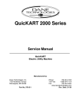
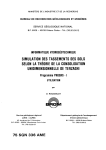
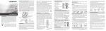
11.DISMANTLING
OF UNIT
3
In case of trouble, etc. necessitating dismantling, please
dismantle in the order shown in the photographs.
Reassemble in reverse order.
1
4
BOTTOM COVER
I
g
CARTRIDGE
2
SCREWS
5
NOTE: Photos of dismantling are those of AP-306, but the order applies to AP-306C and AP-206jC also .
.r
6
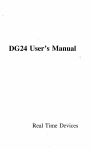
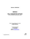
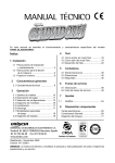
Ill. CONTROLS
1. MODEL AP-206/C
Fig. 1
1.
HINGE
13. PITCH CONTROL (45 rpm)
2 .. SPINDLE
14. PITCH CONTROL (33·1/3 rpm)
3.
TONE ARM
15. TURNTABLE
4.
TONE ARM REST
16. STROBE MARKINGS
5.
TONE ARM lIFTER
17.
6.
MAIN WEIGHT
18. CARTRIDGE
SHELL
7. 45 rpm ADAPTER HOLDER
19. CARTRIDGE
SHELL FINGER LEVER
8.
20.
LOCKING NUT
21.
START/CUT
22.
TONE ARM lIFTER
HINGE
9. STYLUS PRESSURE SCALE RING
10.
ANTI·SKATING
ADJUSTER
11.
BUILT·INSTROBE
LIGHT
PLATTER
RUBBER MAT
LEVER
LEVER
( .Y to Lower ~ to Lift)
12. 45/33·1/3 rpm Speed Selector (.•. 33 .-.45)
NOTE:
AP-206 is not equipped with a cartridge.
7
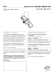
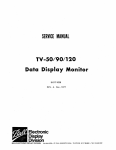
2. MODEL AP-306/C
01-------;.
A.
®f-----~~
(j)f--------=--------1.
®r-----::==--9f------../
Fig. 2
1. HINGE
12. MAIN WEIGHT
2
RUBBER MAT
13. STYLUS PRESSURE SCALE RING
3.
SPINDLE
14. ANTI-SKATING
4. TURNTABLE
PLATTER
5.
STROBE MARKINGS
6.
BUI LT-I N STROBE LIGHT
17. TONE ARM
7.
SPEED SELECTOR SWITCH
18. TONE ARM LlFTER
8.
QUARTZ
19.
LOCKING NUT
9.
PITCH CONTROL
LOCK SWITCH
16. TONE ARM REST
LEVER
20.
START/CUT
LEVER
10. 45 rpm ADAPTER HOLDER
21.
CARTRIDGE
SHELL FINGER LEVER
11.
22.
CARTRIDGE
SHELL
HINGE
NOTE:
AP-306 is~ot equipped with a cartridge.
r:.
8
ADJUSTER
15. TONE ARM LlFTER
IV. PRINCIPAL PARTS LOCATION
1. MODEL AP-206jC
.:,.
,,"
••~---"'+-+()
'"
••
.!I
AUTO
CLUTCH I A I
••
II--'''''--I---'f-
f.
REJECT
~~~SSURE
TONE ARM
•••..•=c===i--t-
~
CLUTCH IB I
WEIGHT
e
"".t--I-----1f--+-
AUTO
MAIN
~gt~S
~. GEAR
t«
$
(i,
M
•••••
TONE
ARM
TONE
ARM
LI FTER
REST
LEVER·-!--~-r------1-----~~
s
i1
'-'
~
TONE ARM
LlFTER
LEVER
~'
BUILT-IN
STROBE LIGHT
45/33
rpm
SPEED SELECTOR
PITCH
CON~RO_ 45rpm)
PITCH
CON ROL,33rpm
".".;c=~~----1f---7-CARTRIDGE
T
SHELL
Fig. 3 AP-206jC Top View with Dust Cover Removed
MICRO SWITCH I SW901 1
POWER SUPPLY P.C BOARDIAP-26411
RELAY P.C BOARD
IAP- 26521
PU
PLATE IAI
PU
PLATEIBI
SEESAW
AUTO
LlFTER
POWER TRANS (T901 1
LEVER
LEVER --~~~---1~~~~----
O-!!!~H--D.D
SPRING
,,*~-~~H-MOTOR
P,C BOARD
IAP- 26421
BLOCK(DDM-331
NEON LAMP P.C BOARD
IAP- 26531
Fig.4
AP-206jC
Bottom View with Bottom Case Removed
9
2. MODEL AP-306jC
\.l--III.,
~
•.•
=;-----
l'lIIIIIIIIJ--t--.,---;r-
MAIN GEAR
iil
<r>
-1..
•
AUTO CLUTCH(A)-~-------~-----+----
__
--+-t--+--
MAIN WEIGHT
~nt~S
R7~~SSURE
~~J0S~~~TI
NG
t::::!!U::::~r---,- TONE ARM LiFTER
M-----..,.---+--
TONE ARM
~ __ --~-_+-TONE
ARM REST
AUTO CLUTCH(B)-~--------0+_-_,r_~~~
REJECT
LEVER
-7----.-----+------!,u.,...
.....
•
~h;C--+-
sw
START/CUT
LEVER
T~
SPEED SELECTOR
SWITCH
CARTRIDGE SHELL
Fig. 5 AP-306/C. Top View with Dust Cover Removed
RELAY P.C BOARD
IAP- 2652)
..,.......-'~;*-POWER
PU
PLATE lA)
PU
PLATE IB)
TRANSIT901)
SEESAW LEVER
AUTO
LiFTER
LEVER
SPRING
•
•
_f~
:;t
hi-
fi'!
~
-'::"'--"~"---D,D
P,C BOARD
IAP- 2642)
_,"'o::J!1I .••.-MOTOR
BLOCKIDDM-33)
PLL P,C BOARD
IAP- 3601)
NEON LANP P.C BOARD
I AP- 2643)
Fig. 6 AP-306/C Bottom View with Bottom Case Removed
10
v.
BLOCK DIAGRAM
1. MODEL AP-206/C
+8
45---33-1/3
ISPEED SELECTORI
Fig. 7
2. MODEL AP-306/C
,-------{STR08E
CIRCUIT
o--+-_'v-op--- + 8
\
\
\L
\~
Fig. 8
11
VI. CIRCUIT
NAND
OPERATION
:=O-X
EXCLUSIVE OR GATE
NOR
:D-x
NOT
(=ANTI-COINCIDENCE)
A 8 X
L L H
L H H
A 8 X
L L H
A 8 X
L H L
L H H
H L H
H H L
H L
L
H L H
H H L
H H L
X= A· 8
X=A+8
L
L
X=A'B+A-
L
B =A878
A---[:>-X
I
x
L H
H L
X=A
Fig. 9
1. GENERAL
The AP-206/C has a D.D (Direct Drive) P.C Board
(AP-2642) that contains a FG (Frequency Generator)
the signal output of which controls the motor. The
AP-306/C has a PLL (phase-Locked Loop) P.C Board
(AP-3601) in addition to the electrical circuit in the
AP-206/C.
The PLL circuit in the AP-306/C consists of a Quartz
Lock Circuit and a Stroboscope Circuit. The stroboscope circuit flashes the neon tube NE901 in
synchronism with the frequency to which the crystal
oscillator frequency is accurately counted down,
while the neon tube NE90l in the AP-206/C is
activated by the line power to flash the Strobe
markings o~ the turntable.
2. SERVO CIRCUIT
1) Operation when the Quartz Lock Switch SW903 is
OFF
(Refer to the D.D Circuit schematic diagram of the
AP·306/C.)
The motor incorporates a FG coil that produces
FG signal as the motor rotates. The FG signal
frequency is 20 Hz for 33·1/3 rpm and 27 Hz for
45 rpm.
The FG. signal is magnified through ICI (4~8).
The magnified FG signal is clamped to positive
side by R40 and VRI, and enters IC2 CD.
In IC2, the signal is waveform-shaped and frequency-doubled, The doubled signal is fed to IC3
CD, as an input to Mono Multi. The Mono Multi
provides a characteristic that its stable state is
inverted by an external trigger into the unstable
state, where it remains for a predetermined time
before returning to the original stable state. The
pulse output of Mono Multi IC3 @ is smoothed
by C7 to DC, which-is led to ICl ® as the voltage
to be compared. When the Quartz Lock Switch
SW903 is off, a reference voltage is applied to
ICl ®.
The voltage at ICl ® is compared with the
reference voltage at ICI ®, and the output
appears at ICICD<the output at ICl CD is passed
12
through the phase correction circuit, consisting of
C9 through Cl1 and Rl8 through R20, to TR1.
TRI makes current flow through the Hall Elements HI and H2, which are installed in position
under the rotor magnet of the motor. The voltage
developed across each Hall element is in proportion to the current flowing through the Hall
Elements and the strength of the magnetic field of
the rotor magnet.
The voltages output of the two Hall elements are
supplied to the motor drive amplifier, consisting
of IC4 (4~8), TR2 and TR3 and IC4 (1~3), TR4,
and TR5, to control motor speed.
If the motor speed is made late by some cause, the
FG signal frequency becomes lower. The width of
the pulse output of the IC3 Mono Multi becomes
wider. This increases the comparison voltage at
ICI ®, which in turn raises the voltage output of
IC 1 CD. The result is an increase of the current
flowing through TRl and the Hall elements HI
and H2. The current increase the motor drive
amplifier so as to make the motor speed fast.
2) Operation when the Quartz Lock Switch SW903 is
ON
(Refer to the PLL Circuit schematic diagram of
the AP-306/C.)
The 4.42368 MHz signal generated by the crystal
oscillator is delivered through TP-l to IC2 ®.
The Flip-Flop in IC2 halves the oscillation frequency of 4.42368 MHz. The frequency-halved
signal is delivered as a clock pulse to IC3 @,
which counts it down to 1/27 (81.920 Hz) for
33-1/3 rpm or 1/20 (110.592 Hz) for 45 rpm
according as set by the Speed Selector Switch
SW902. The count-down signal, which appears at
IC3 @, is further counted down to 20 Hz for
33-1/3 rpm or 27 Hz for 45 rpm at IC4 CD. This
output signal of IC4 CD enters the comparison
circuit in IC5 (j), as a set pulse.
On the other hand, the FG signal fed through the
D.D circuit to the PLL circuit is waveform-shaped
by the Schmitt trigger in ICI (I~13),
and is fed
, ..
through IC1 @, and R3 to IC5 ® as the reset
pulse. The reset pulse of 20 Hz for 33-1/3 rpm or
27 Hz for 45 rpm shaped from the FG signal is
compared with the above-mentioned set pulse
entering IC5 (j), and the output appears at IC5
@.
The output pulse is smoothed by the low-pass
filter, consisting of C9, C10, and R5 through R7,
and enters IC5 CID, then the inverted output is fed
from IC5 CD. The output of IC5 CD fed through
RS and SW903 to IC1 @, in the D.D circuit as the
reference voltage. In short, when the Quartz Lock
Switch SW903 is off, the reference voltage is made
of the +B voltage, while when it is on, the pulse
made of the FG signal is compared with the pulse
generated by the crystal oscillator to produce the
reference voltage. The succeeding operation is
similar to the one when the Quartz Lock Switch is
off.
':..•
)0',
,-,-
3. STROBE LIGHT CIRCUIT
(Refer to the PLL Circuit schematic diagram of the
AP-306/C.)
The 4.4236S MHz signal generated by the crystal
oscillator is delivered through TP-1 to IC2 @. The
Flip-Flop in IC2 halves the oscillation frequency to
2.211S4 MHz. The halved signal is fed from IC2 CD,
to IC3 @. IC3 counts the frequency down to 1/27
for 33-1/3 rpm or 1/20 for 45 rpm.
The count-down signal is fed from IC3 @, to IC4
@.
IC4 further counts the signal down to 160 Hz at IC4
@, 320 Hz at IC4 @ and SO Hz at IC4 @ for
33-1/3 rpm or to 216 Hz, 432 Hz and lOS Hz for
45 rpm, respectively. These output signals are input
to the NOR circuit of IC6 Cl ~5). The NOR circuit
outputs from IC6 CD, SO Hz signal for 33-1/3 rpm or
10S Hz signal for 45 rpm. The signal is fed through
RIO to TR1 to turn on and off, which flashes the
neon lamp NE90l.
Reference:
~ogic Symbols. and Their Truth Table
13
VII. MECHANICAL
ADJUSTMENT
'"
'Z
STYLUS PRESSURE
SCALE RING
" L".,i'
[ANTI-SKATING
ADJUSTER
Fig. 10
1. STYLUS PRESSURE
ADJUSTMENT
(Refer to Fig. 10)
1) Plug the power cord into a wall outlet of rated
voltage.
2) Unlock tone arm.
3) Bring the tone arm over to the turntable to start
the motor. Pull the Start/Cut lever toward you and
release immediately.
4) Wait until the tone arm lift is completely lowered.
5) Keep the tone arm between the turntable and arm
rest without touching either.
6) Rotate the main ,,{eight backward and forward
until the tone arm is in perfect horizontal balance.
(Zero balance is attained.)
CAUTION 1: Be sure that the Antiskating Adjuster is set to zero.
2: Bi·~areJul not to damage the stylus.
7) Without moving the, main weight, turn the stylus
14
pressure scale ring only to match the "0" mark
with the marker on the weight shaft (See Fig. 10).
8) Turn the main weight counterc1ockwise (as viewed
from the front) with the stylus pressure scale ring
until the marker on the weight shaft corresponds
to the desired stylus pressure on the scale.
NOTE 1: The AP-206 andAP-306
Black and
Silver Panel Models do not come equipped with cartridge.
2: The recommended stylus pressure for
the supplied stylus (AP-206C and
AP-306C only) is 2 grams. However, in
the case of outside interference, more
pressure may be needed for stability.
The range of adjustment is from 0 to
3 grams.
9) Set the anti skating adjuster to correspond with the
stylus pressure. (Fine adjust if necessary.)
1,..,'
•
Fig. 11
2. OVER HANG ADJUSTMENT
(Refer to Fig. 11)
The distance of the stylus from the turntable shaft
when the tone arm is at the turntable is called "overhang". Although the overhang is preset at the factory
for this model, adjustment may be necessary when
the cartridge is replaced. For your convenience, the
rubber turntable mat has indicator groove at the
center for easy overhang adjustment. Bring the tone
arm to the center of the turntable. Adjust the cartridge position in the cartridge shall so that the stylus
position is even with the outside groove ring. The
cartridge position is adjustable by resetting the screws
on the cartridge shell.
15
MICRO
SWITCH
(SW901J
PU PLATE (61
Fig. 12
CABINET
3. SLEEVE POSITION ADJUSTMENT
(Refer to Fig. 13)
The sleeve position adjusts antiskating feature.
1) Put the tone arm in the "stop" state, or on the
arm rest.
2) Set the sleeve, located between the PU Plate and
the chassis, to approximately 45° position as
shown in Fig. 13.
4. PU PLATE ADJUSTMENT (Refer to Fig. 12)
Fig. 13
16
1) Put the tone arm in the "stop" state.
2) Loosen the screws (b) and (c).
3) Adjust the PU plate (A) so that it may actuate the
micro switch to turn on or off properly.
4) Tighten the screws (b) and (c).
5) Temporarily set the screw (a) in a half screwed
position.
, ..
~TONE
TONE
ARM
t
ARM LlFTER
5.5 to
6,Ocm
ABOUT Bmmrl
~-'lr°~
1----
Fig. 14
M,USIC, etc.
LAST
GROOVE
Fig. 15
5. LIFTER HEIGHT ADJUSTMENT
(Refer to Fig. 12 and Fig. 14)
6. AUTOMATIC RETURN POSITION
ADJUSTMENT (Refer to Fig. 12 and Fig. 15)
1) Adjust the screw (d) (see Fig. 12) until the tone
arm fits to the tone arm lifter as shown in Fig. 14.
2) Check to insure that the height of the stylus is
around 8 mm above the disk surface when the
tone arm is supported on the tone arm lifter.
3) Make certain that silicon oil remains on the tip of
the lifter spring. If not apply it to prevent
mechanical noise.
1) Adjust the screw (d) (see Fig. 12) until the tone
arm returns automatically at a desired point.
NOTE: The automatic return range is around 5.5
to 6.0 cm from the center of a 30 cm disk
(see Fig. 15).
Turning the screw clockwise shifts the
return point inward, and turning counterclockwise shifts it outward.
2) After adjustment, play a 17 cm and 30 cm disks
bak to check that the tone arm returns at a correct
point.
17
VIII. ELECTRICAL ADJUSTMENT
0
-
- --
15 14
- -------
13 12
DTP-I
11
10 9
'"0 0
~
0
VR4
~
17 18 19
••••
,:~.~~,
§
OFF-SET
§
o
0
VR2,VR3
0
VR2
lOOKS
7
6
5
0
4
0
32-
0
~OO
500B
DUTY
RATIO
16
8
VR5
zoxa
VOLTAGE
I-
~
VR6
300KS
TORQUE
DIFFERENCE
SPEED
0
VR3
lOOKS
2021
--
Fig.16
IDEAL
(All peaks are at the same level)
0
Direct Drive P.C Board Adjust Points
BAD
(Peak levels are not equal)
Fig. 17
1. DIRECT DRNE
p.e
BOARD
ADJUSTMENT
1) Off-set Voltage Adjustment (VR4, VRS)
a) Disconnect the motor connection wire. (Open
pins 4 through 11 and 14,15 then leaving the
other pins connected.)
b) Connect a DC voltmeter (digital voltmeter)
between pins 6 and 8 (ground).
c) Short the circuit of pins 9 and 10.
d) Power "ON" (move the tone arm)
e) Adjust VR4 until the output at pin 6 IS OV ±10
mV for the AP-206/C and 80 ±1O mV for
AP-306/C.
f) Power "off' and open the circuit of pins 9 and
10.
g) Connect a DC voltmeter (digital voltmeter)
between pins 7 and 8 (ground).
h) Short the circuit of pins 4 and 5.
i) Power"ON" (move the tone arm).
j) Adjust the VR5 until the output at pin 7 is
OV ±10 mV for AP~206/C and 80 mV ±10 mV
for AP-306/C.
* After Off-set Voltage Adjustment, make the
connection as normal position.
'"
:.,:.. •..
18
2) Duby Ratio (1: 1) Adjustment (VRl)
a) Connect an oscilloscope to rp-I.
b) Set the SPEED selector to the "33-1/3" position.
For the AP-306/C, release the Quartz Lock
button to the OFF position.
c) Move the tone arm to rotate the motor.
d) Adjust VR1 until the oscilloscope shows a
waveform or as Fig. 17.
~,ow,
ROW 2
ROW 3
ROW 4
Fig. 19
Fig. 18
o
yg ~
OSC FREQUENCY
~~o~~
00
::~ 0 0 ~ 'm'
o
5'g'KIB QUARTZ - LOCKED
PHASE
ANGLE
.
4
3
o
o
I.
o
Fig. 20 PLL P.C Board Adjust Points
3) Torque Difference Adjustment (VR6)
a) Connect a dual-channel AC voltmeter to pins
6, 7 and 8 (common ground).
b) Set the Speed selector to the "33-1/3" position.
For the AP-306/C, release the Quartz Lock
button to the "OFF" position.
c) Move the tone arm to rotate the motor.
d) Adjust VR6 until the outputs at pins 6 and 7
are of the same level.
NOTE: As the output frequency is as low as a
few Hz, the voltmeter needles will
vibrate minutely. In the state of
correct adjustment, the two needles
will seem intertwining as shown below.
CAUTION: In the adjustment, only make
both voltages equal as these varies
with the motor rpm.
4) Speed Adjustment (\'R2, VR3)
a) Set the Speed selector to the "33-1/3" position.
(For the AP-306/C, release the Quartz Lock
button to the "OFF" position.)
b) Set the Pitch control to the center.
c) Move the tone arm to rotate the motor.
d) For the AP-206/C, adjust VR3 until the Strobe
markings on the first line for 50 Hz power or
the second line for 60 Hz .power is seen standing still. For the AP-306/C, also adjust VR3
until the single Strobe markings is seen standing
still.
e) In turn, reset the Speed selector to the "45"
position.
f) For the AP-206/C, similarly adjust VR2 until
the Strobe markings on the third line for
50 Hz power or the fourth line for 60 Hz power
is seen standing still.
NOTE: It is important
that the Strobe
markings should not rotate in the
reverse direction of the motor, or
rightward as in the above line drawing.
2. PLL P.C BOARD ADJUSTMENT
(Model AP-306/C only)
I) Adjusting the Oscillation Frequency (VCI)
a) Connect a frequency counter to TP-l and pin 5
(ground).
b) Set the Speed selector to the "33-1/3" position.
c) Move the tone arm to turn power on.
d) Adjust VC1 until the frequency counter reads
4,423,680 ±1O Hz.
CAUTION: For turning VC1, use a RF adjusting screwdriver.
19
22 ±2msec
AROUND
2V
7.5V
to 4V
OV
Fig. 21
DOWNWARD)
(
PULSE
OV
Fig. 22
2) Adjusting the Quartz-Locked Phase Angle (VRl)
a) Connect an oscilloscope to TP-2 and pin 5
(ground).
b) Release the Speed selector to the "33-1/3"
position.
c) Depress the Quartz Lock button in ON.
d) Move the tone arm to turn power on.
e) Adjust VRl until the width of the upward
pulse above 2 to 4V is 22 ±2 msec when the
Strobe markings is seen standing still, as Fig. 21.
(oscilloscope-DC Mode)
CAUTION: The upward pulse around +7.5V
shown above may change to
downward pulse (OV) below 2 to
4V with VRl turned as Fig. 22.
Be careful not to measure the
width of the downward pulse, It is
checked in a simple way that the
upward pulse will change to
downward pulse by loading on the
platter by hand.
20
IX. CLASSIFICATION
OF VARIOUS
P.C B,QARDS
1. P.C BOARD TITLE AND IDENTIFICATION NUMBER
Utilizing Model
,
P.C Board Title
P.C Board Number
Power Supply P.C Board
AP-2641
AP.iO'g/c,
D.D P.C Board
AP-2642
AP-206/C, AP-306/C
Neon Lamp P.C Board
AP-2643
AP-206/C, AP-306/C
Relay P.C Board
AP·2652
AP-206/C, AP-306/C
PLL P.C Board
AP-3601
AP-306/C
AP-306/C
21
N
N
N
-
(j
'-' 0
~ ~
o
'"0
. 0
ISPEEDI
I SPEEDI·
I I
I
.:; ;1_ ~
r ~
•
"''''~
~~ '"
€>
AP-3601
SW902
45_33-1/3
,-
r
ON-OFF
9l'
~
~
2
N
N
0
o
"'WI
Q
•
~
,
I
I
I
~
0
IVR2200KB
I
J
@)@@H~
"U
I
:-5 ~
I\)
-i
C-i.,
Q')
~ ~ z~
0" ,,-"
- z Z oa
s: f:= ~~
o
(f)
rU)
~®~
~©~®
~~
~~
~rn o
~
N
ov
IK
•.
J:C_2
iiL•.•
, ....• CD
:.;.,
~
~T
0'1-1.•
or03V~
7.lV101 Nr-e
CO 0,01
~
3~rv1N~~ ..• gI
-t.........
~C-b71v 0
R40470
R31K
-w.r-
T
R~
til-
-';01--
O.3VI 0,
Re
-w,-.
-
~
~
~N
o.~-e.l'7,1v
RI2
[!]9
8.2K
RI4 2.2K
~
RI 270
....."".,...
RI6
~<i
~~
II\'"
'»-;;
58K
...w.,-.
_. ..
R21
~
1/2W
R3447K
9.6V ~
;
~
R36 IK
--wr-
O.IV
CII
-'.!]--o
C9
~
et
V
R420K8
T
~:J--
02
IS1588
~o
:j0)
:jo
0)
C210.047
R3547K
....-wr-
OIl('
~l(
-9.av
0605Z-IOU
....••....
9.SV
~E:
~
V
~
CI5 100110
~
~9.!II~1-~
<
CI4
~
100/10
tv]...,j
b-V
101
~K
Nr~
Ulr.st8V
"'iY'_~ .•
~
.....y..-.
T
T
0,
I
,
I
I
I
I
I
z
T
R~
~
R293.3K
oJWr--o
CIB
100/10
C20
470125
o-fr-o
L~_
,ORG
®
IORG
]
0
IBLK
o
ililililiI
~mw
U.
~
0
0
I
Oi
MOTOR BLOCK M901 DDM -33
C2'
470125
o-j)----o
0--1)---0
~
r
Vl
R39470
OlN~
4
~
R6
noo
()~
>
0-\4-0
R3127K
I
I
C 17100/10
0
0-+\:---
'00K8
~
0
'"0
0'
~
@R30330K®
T
I
o-{!--o
-<
>
_
(j
t::e
C23 IOOI2~
051-IOU
C200.047
~~
f
"!j
Vl
~
~ ~.3V
6
c::
tD
;:r~3V
-I~
R25330K
s
fT1
~o
IJI
~fiA~.i' ~
@®
tw~
~o
~ID
tD
T-_.~~
...".....
-
~ ~~~
~o
---.-"--0
....w.-.
R2433K
4,7/25
®
::r"
R23150
470
R371K
...w.--o
@
T
11 t
'W
0;
C160.047
~
Q.47/25(M)
....",.,...
~~+
..r.)~+~ - ~
dlijm ~~f.v
•. .{?_~..
0.811
270
...-1)-
~K
r
R22 150
o---Wr-<o
2.2125IM)
..,."....
o--fr-o
t
~£
in
~
RI7 lOOK
--n--'"
Cl 100/10
J,r
RI9561(
=1~t- ~
o
C22 10012.
8!!
~~ ~~ !
ll
tll""0
NO
151MB
R92.21<
7,~~
"01;;)1-4'
7.~C~.!1I
R2 330K
I
@' @. @.
.........-
eZK
CB 0.15
C~~
IIRI2KB
RIO
7.~-l10'l1D~"
~
~
o
~
7.~iOlID~~~gb
R5 470
~
C6 QOt
("I
I
I
01
ovG1r.6V.....w,...
~
I
VR' 200KB
R42 .6K
;;;;: .s+ =j"
5 ~ ~~~ ;:,
:U-iG">-1
~@
IK
--w,-.
=
:~
1
I~ I
1-<
I
R41
l>
(J)
g
....w..-.
I
I
IT
VR2 200KB
l~
Cl
I
@o @o @.J
R6
I
I
~
I
I
i
~
~
"'"
!0
c
I
~
§
IX)
CI\
~
I
::a
N
"?
~ ~
txl
~()
l>
~
~
2
D:"'~
u;"'
()
IQUARTZ LOCKI
e
~!f< r<
o
<0",
en",
en",",
en
_Vl
~ 0
SW903
~<
N
~~rn~
l>"
~~m
...,-" c,
;0
("'l
~
~
m
N
m
m
~
°IC
~I:II:
m
,
g I: ~~
POWER TRANS
T901
2) PLL P.C BOARD AP-3601 (Model AP-306jC only)
SW902
45 -.,..33-1/3
rW:..:.H:..:.T.:..I"'BL"'U
~
~
E C B
2SC2229
o
o
le 1
IC2
IC3
IC4
res
res
TC4069BP
TC4013BP
TC50eop
TC4040BP
TC50BIP
TC40028P
RIO 3.3K
~
r-_.::.W:..:.HT'--l_~
f-:O.,V
NE901
<,
L-_.!!W",H,-T-l__ ~
CIOO,I
•........••........•
02
552770
.-....
RI! 8.2K
TRI 25C2229(0)
.~.
o
,
,
®
CD
I
I
I
I
VLT
IVLT
F4
UtT
C.IA 2!50V
CSA,AAL
IOOmA 125V
UK,CEE
[CD mAl
0
•J
T9QI
23
3) POWER SUPPLY P.C BOARD AP-2641 (U/T)
o
F I
&.
~WHT
POW~:O~RANS
__
.•.•
----=B"'RN'--+--
0
__
[
__ -"R",E,,"D~
0
••
&.
o~n
SWI
220/240V _IIO/I20V
®
&.
o
o
(£)
•
~R2
IOK
Yt'.----e
o
0
®
0---
T
WHT
f=------'
-------
.~.
I
BRN
NOTE
MARK X· INDICATES
MODEL AP-206/C
ONLY
Orr.DlCATES SA!'"ETY CRITICAL CO!o'J>ON!NfS FOR CONTINUED SAFETY,
R[PLACE SAFETY CRITICAL COMPONENTS ONLY WITH MANUfACTURER'S
RECOMMENOED PA.'I'TS
•
.
A'JERTISSEIo'ENT: &'IL INOI
U:S COMPOSANTS CitITIOUES
DE SURETE.
IoI-AlNTENIR LE OEGRE oe: SECURlTE
DE t,' APPAREll NE ittMP!..ACER US
CO"?OSANTS
LE FONCnoN~'E"'ENT
EST CRlTIQLI:: POUR LA SECUftlTE
OUE F'oUl DES PIECES RECOJ.!MAI;JEES P.uI LE FASRICA.'n
WM/\1 'G·
ocvr
4) POWER Sq-PPLY P.C BOARD AP-2641 (AAL, CSA)
I CSA
I
AAL
®,
(i).-----_
L
o
ORG
~w'" "'" [
----.0
BRN
---
T901
RED
0
&.
-e
0
0
0
Cl
--- .•®
.&.
BRN
••...• 0
®
'r " r
q-
0 ~
~~
'"
0
0
T
I
.~. R2 IOK
0
0
~---------.~.
NOTE
MARK
WoloR"""'G.OIN:XCIlTES
s..:.FETY CRITlCIIL COII.f'QNENTS FOR CONTlNUEO 5I1.fETY.
REPlACE
SAFETY CRITICAL COMPONENTS ONLY WITH MAMlFACTURER'S
RECOMMENDED PARTS
•
.
AVERTISSEMENT:.!.IL
INDIDU LES COMPOSANTS CRITIQUES DE SURErE. POUR
MAINTENIR u:: DEGRE DE SECURITE DE L'APPAREIL NE REMPLACERLES
CONPOSANTS [XmT LE FONCTIONNEMENT EST CRITIQUE POUR LA SECURITE
QUE PAR DES PIECES RECOMMANOEES PAR LE FABRICANT
24
®.r---~-- '"HT
.)0:. INDICATES
·i· NE901
&.
,"HT
MODEL AP-206/C
ONLY
5) POWER SUPPLY P.C BOARD AP-2641 (UK, CEE)
IuKl
~
0.
0------
L~-----C5--~=-~
o
o
= = =
.1,.
')(-R210K
o
eT
I
BRN
o
.
o
AIr\
0
®.r---~--
WHT
.~. NE 901
®•.------------.t-'--------'
WHT
.~.
NOTE
MARK X· INDICATES
MODEL
AP-206/C
ONLY
\to'A!'I.;IM: All.
cerrs s:.FETY CRITICAL CQ!,I.PO:'ENTS.
FOR CONTI"'1JEO SAFrTY,
REPt.:.CE SAFETY CRITICAL COMi"OHENTS ONLY WITJol MA.'ruFACTUR£R'S
RECO,,".MENOED
PA.'rrS
~
AVERnSSElo!EIIT. e IL lNOlQU LES COto'?OSANTS CRITIQUES DE SURETE. POUf!
MAlNTENIR LE DEG~ DE 5ECU!lITE DE L' AFPARtIL he; ROf."'LACER
U:S
CONPO$ANTS OOtH LE FOUCTlON'>EM(HT
EST CRITIQUE POUR LA SECURlTE
QUE PAR DES PIECES RECOMhtMDEES ?AA LE FABR1CA.'iT
25
MEMO
~.,
26
MEMO
27
MEMO
28
MEMO
, ..
-.:
•..
29
MEMO
-"
....
" ,
.,1.."
30