1
Service
and
Repair Manual
Service Manual
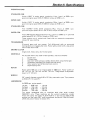
INTRODUCTION
This service manual has been compiled t o give HOWARD Dealers and their
staff, a sequence of operations t o enable the servicing and repair of a
HOWARD GEM ROTAVATOR t o be carried out quickly and effectively.
Because of our policy of continuous improvement, this manual should
always be used in conjunction with the latest service bulletins covering the
GEM. These service bulletins are distributed t o all HOWARD horticultural
dealers when they are first printed, and back issues are available from us on
request. HOWARD GElVl service bulletins after bulletin H.63, should be
kept with this manual, and a note added t o the index of each section
affected, so that an up t o date record of modifications is kept.
A t the start of each section, there i s a list of ordinary workshop tools that
will be required when carrying out the repairs covered by that section.
Some 'special tools' may also be required, of which a complete list can be
found under 'special tools' section 'A'.
In addition to the special tools and equipment used during some repairs, a
hydraulic or hand operated fly press (of the type found in most workshops)
will be required when removing and fitting oilseals and bearings.
Before assembly of component parts, remove dirt and grease and, in the
case of new parts, remove the special rust inhibitor, otherwise the function
of the component may be restricted when in operation. When ordering
spare parts, DO NOT confuse the illustration numbers used in this manual
with the TRUE part numbers found in the official parts list, form number
L.693.
While every effort is made t o ensure that the information contained within
this manual is correct, any errors which may occur, should be brought t o
the attention of our Service Department.
Specifications, torque loadings, special tools.
Engine removal, clutch, clutch shaft, air cleaner.
Gearbox, wheels and hubs.
Controls.
Main frame, handlebars, shields.
Rotor, rotor clutch, drive chain, backplate.
Lubrication, maintenance and fault finding.
SECTION
PAGE
A
B
C
D
E
F
G
3
7
19
37
45
51
61
Although this manual refers t o machines in current production, reference
i s made, where possible, to the history of the various assemblies and
components.
ILLUSTRATION REFERENCE
The figures in brackets after component names refer t o the illustration
number of the component, within thediagram specified by that instruction.
e.g. (C25-35) is Section 'C' illustration '25' illustrated component
35-Reverse idler gear.
Howard Gem
HISTORY OF THE GEM
The HOWARD GEM has been developed over a period of many years.
Since its introduction in 1942, there have been five series of GEM, each
series being an improved version of i t s predecessor.
SERIES I
The original GEM was fitted with 'bicycle type' handlebars, but was not
equiped with either a differential or a reverse gear. Series 1 machines were
produced from serial number 101 up t o machine serial number 4800, and
these machines were fitted with the HOWARD B.J. engine.
SERIES ll
'Swinging type' handlebars and a differential were introduced a t the start
of the series I I GEM, and later they were equiped with a reverse gear
operated by a lift up lever. Series I I machines were produced from serial
number 4801 up t o machine serial number 14784, and these machines
were fitted with the original HOWARD B.J. or a J.A.P. 600cc engine.
SERIES Ill AND I V
Production of series I II and I V machines overlapped. The basic machine
remained the same for both, only the engines were different.
Series I l l machines were produced from serial number 14785, and were
fitted with either the HOWARD B.J. or a J.A.P. 600cc engine. During
production of the series I II, the first series IV machines were phased in.
These machines were fitted with a new HOWARD engine, the 180° Twin.
From machine serial number 38760 series l V machines only were produced,
but were fitted with an improved version of the twin engine-the
HOWARD 360° Twin -or alternatively a water cooled Sachs diesel engine.
Series IV machines were discontinued a t machine serial number 47066.
SERIES V
This is the current series of GEM, which was introduced a t machine serial
number 47067. Machines up t o serial number 2541824 were fitted with
an up-rated version of the HOWARD 360° Twin engine, or the Sachs
diesel. From machine serial number 2541825, a Kohler K.301T engine has
been fitted in place of the twin, or from machine serial number 2571945,
an alternative diesel engine, the Hatz ES.780, has been used. An improved
version of the Hatz engine has been fitted from machine serial number
250A1021, and is designated the Hatz ES780U.
SUPER GEM
The super GEM is an up-rated version of the Series V model produced
specifically for contract work where greater strength and power are
required. Super GEM machines are fitted with either a Kohler K341 petrol
or Hatz E785 diesel engine.
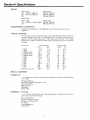
Section A - Srpecifications
SPEC1FICATIONS
STANDARD GEM
Kohler K301T 4 stroke petrol, producing 11h.p. (rnax.) at 2800 r.p.m.
governed engine speed 22 Ib-ft (30Nm) torque a t 2200 r.p.m.
SLIPER GEM
Kohler K341T 4 stroke petrol, producing 15h.p. (rnax.) a t 2800 r.p.rn.
governed engine speed 28 Ib-ft (38Nrn) torque a t 2100 r.p.rn.
STANDARD GEM
Hatz ES780U stroke diesel producing 9h.p. (max.) a t 3000 r.p.m.
governed engine speed 19 Ib-ft (25.75 Nm) torque a t 2100 r.p.m.
SUPER GEM
Hatz E785 4 stroke diesel producing 1 'I h.p. (rnax.) a t 3000 r.p.m. governed
engine speed 23 Ib-ft (31Nm) torque a t 2100 r.p.rn.
These engines are air cooled and fitted with an automatic compression
release for easy starting.
TRANSiVllSSlON
3-forward gears and one reverse. Full differential with an automatic
locking device on engaging the rotor. Rotor safety clutch with a slip action
when under shock load.
ENGINE CLUTCH
Single plate, heavy duty, dry friction plate.
CONTROLS
All situated within easy reach of the operator, and are as follows:
1.
Clutch lever.
2.
Throttle lever.
Gear lever with spring out safety device when using reverse gear.
3.
Handlebars adjustable for height and side swing.
4.
Rotor selector and differential lock control.
5.
6.
Depth setting lever.
ROTOR
Rotor speed 188 rpm a t an engine speed of 2800 rprn. Rotor widths of
20" (51 em), 24" (61 cm) and 30" (76 cm). Tillage depth is adjustable
down to 9" (23 crn).
WHEELS
20" overall diameter using 4.00 x 12 2-ply pneumatic tyres. Tyre pressure
is 20 1blin2 (1.4 kg/cm2).
LANDSPEEDS
At 2800 rprn. engine speed:-1st gear - 0.96 mph. - 1.4 kph
2nd gear - 1.46 mph. - 2.3 kph
3rd gear - 3.05 mph. - 4.9 kph
Reverse - 1.85 rnph. - 2.9 kph
The above landspeeds refer t o machines built after serial number
250A1021 only. These machines are the current production model,
fitted with either the Kohler K.301TIK341T or the Hatz ES.780UIE785
engines and the l a t e s t 3617 ratio crownwheel and pinion. (See the crownwheel and pinion history in section 'B').
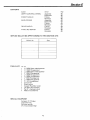
SectionA - Specifications
WEIGHT
Petrol model
Diesel model
20" - 644 Ibs (292 kg)
24" - 672 Ibs (305 kg)
30" -
652 Ibs (296 kg)
674 Ibs (306 kg)
790 Ibs (358 kg)
SUPER GEM
Petrol model
24"
30"
Diesel model
630 Ibs + dead weights 746 Ibs (338 kg)
862 Ibs (391 kg)
-
RECONlNlENDED LUBRICANTS
Gearbox and chaincase - SAE 90 gear oil, all others oiling points use
engine oil.
-
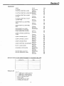
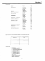
TORQUE LOADINGS
All nuts and bolts must be kept tight, and as a guide the following table of
torque loadings may help. In the absence of a suitable torque wrench,
spanners of the length specified in the right hand column of the table
below, will, if used to maximum effect by the average man, give comparable
loadings.
Thread size
t"
BSW
BSW
2'' BSW & UNC
g'BSW & UNC
1," BSW & UNC
2'' BSW
2" BSF
5" BSF
BSF
16
1," BSF
5" BSF
2" BSF
5"
-
i6
Blade bolt and nut
Torque loading
lbs/f t
kg/m
Spanner length
inches
cms
5
6
7
8
10
18
5
6
8
10
18
36
12
12.5
15
17.5
20
25
45
12.5
15
20
25
45
91.5
30
SPECIAL EQUIPMENT
HERMATITE
- is a sealing compound used, where specified, to prevent the possibility
of oil leaks.
Manufactured by :Kenilworth Manufacturing Co. Ltd.
Hermatite Works,
West Drayton,
Middlesex,
ENGLAND.
SAMPSON C. 110 GLUE
- is an Amyl Acetate glue used, where specified, to secure the fibre discs
to the rotor clutch drive discs.
Manufactured by :Samuel Jones & Co. Ltd.,
Sampson Adhesive Mill,
St. IVeots,
Huntingdonshire,
ENGLAND'
-
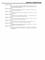
Section A - Special Tools
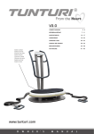
SPECIAL TOOLS
The following special tools w,ill be required when carrying out certain
repairs, and as they are simple in design, can be easily produced from the
following dimensioned drawings.
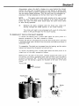
SPECIAL TOOL S.1:i s a clutch shaft puller used, as specified in instruction '3a' Section 'B', to
remove a broken clutch shaft.
SPECIAL TOOL S.2:is a hub puller used, as specified in instruction '2' Section 'C', t o remove
the wheel hubs.
SPECIAL TOOL S.3:is a pegged tool used, as specified in Section 'C'. 'To dismantle the axle
assembly: t o remove the loose hub gear bearing.
SPECIAL TOOL S.4:is an axle shaft puller used, as specified in Section TF'Rotor stub axle-to
remove', to remove the unbroken stub axle.
SPECIAL TOOL S.5:is a pegged tool used, as specified in Section 'F' Rotor drive shaft - t o
remove', t o remove the rotor drive shaft sprocket bearing.
SPECIAL TOOL S.6:is a pegged tool used, as specified in instruction '89' Section 'C' t o remove
the bearing from the gearbox jackshaft.
SPECIAL TOOL S.7:is a pointer used in conjunction with 2-2 " BSW nuts, as specified in
instruction '5b' Section 'B', t o enable the crownwheel to pinion backlash
t o be assessed.
Section A - Special Tools
72
D r i l l and t a p t u b e
t o accep'I L .-.r.
,-5. UIVL
x 1" l o n g
square headed
setscrews
D r i l l and t a p bar t o accept 2
3,
8 ' U N F x 2" l o n g setscrews.
.
SPECIAL T O O L S . l
6" dia.
I
S P E C I A L T O O L S.3
%" U N C x 2" l o n g
%" U N C x 3" l o n g setscrew
.
"
U N C n u t welded
S P E C I A L T O O L S.2
I
S P E C I A L T O O L S.4
w e l d t h e n f i l e t o shape
of stub axle.
2 pins
S P E C I A L T O O L S.6
S P E C I A L T O O L S.5
2 Holes
\c'
Dia.
S P E C I A L T O O L S.7
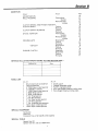
Section B
CONTENTS
Subject
Action
ADJUSTMEIVTS
BELL HOUSING
Fitting-Hatz
-Kohler
Removal-Hatz
-Kohler
CLUTCH SHAFT AND PINION HISTORY
CLUTCH SHAFT
Fitting
Removal
CLUTCH SHAFT BEARING
Fitting
Removal
DRIVE ADAPTOR
Fitting-Hatz
-Kohler
Removal-Hatz
-Kohler
ENGl blE-HATZ
Description
Fitting
Removal
KOHLER
Description
Fitting
Removal
ENGINE CLUTCH
Assemble
Dismantle
Fitting
Removal
Page
18
11
10
11
10
8
16
13
15
15
11
10
11
9
8
17
10
8
17
9
13
12
16
11
SERVICE BULLETINS APPERTAINING T O THIS SECTION ARE:Date
Bulletin No.
--
--
--
----
TOOLS LIST
No. o f f
No. o f f
1
1
1
1
1
1
1
1 Small punch
1 CopperIRawhide mallet
1 Pair 6" engineers pliers
1 Pair right angled internal circlip pliers
1 Pair straight internal circlip pliers
Small (electrical) screwdriver
Large screwdriver
M" BSW Open ended spanner
M" BSW Box spanner
;"
BSW Open ended spanner
;"BSW Ring spanner
'-" BSW Ring spanner
AF Ring spanner
2"AFBoxspanner
g" AF Open ended spanner
;" AF Ring spanner
,'," Sq. Extended box spanner
12mm Open ended spanner
13mm Open ended spanner
'Z,r
1
1
1
1
1
1
SPECIAL EQUIPMENT
Hermatite
Steel rule
Containerltray of a t least 6 pints capacity
SPECIAL TOOLS
Special tool S. 1
Special tool S.7 and 2.;" BSW Nuts
Section B
HISTORY
ENGINES
The Kohler K.301T has been fitted from machine serial number 2541 825
and is a 477cc 4-stroke petrol engine of 10hp.
From machine serial number 2571945, the Hatz ES.780 diesel engine has
been available as an alternative t o the Kohler engine. The Hatz i s a 500cc
4-stroke diesel engine of 10 hp. An improved version of the Hatz engine,
having an antivibration front cover and designated ES.780U, has been fitted
from machine serial number 250A1021.
ENGINE CLUTCH
All Kohler and Hatz engined machines are now fitted with a single plate
clutch. Machines prior t o serial number 2571414, were fitted with a double
plate clutch, and the following parts are required i f converting the clutch
assembly t o the single plate version.
Part number
Part description
288
255
250
Thrust sleeve
Distance piece
Special bolt
No. Off
1
4
4
The clutch assembly should be rebuilt substituting these parts for the
existing components, and one fibre disc and one loose plate should be
discarded from the original assembly. A new clutch shaft - part number
25009 - will also be required.
CLUTCH SHAFTICROWIUWHEEL AND PINION
The crown wheel and pinion were changed on GEM 24" models - machine
serial numbers 2592305 and 2306; GEM 30" models - machine serial
numbers 2591063, 1067, 1069, 1070, 1138, 1139, 1189, 1190, 1191, 1394
and 1451, and all GEM V models from machine serial number 250A1021.
The ratio of the gears was changed from 3619 t o 3617 in order t o reduce the
forward travel speed of the machine, and thus increase i t s performance.
The later ratio gears can be supplied and fitted t o machines prior t o machine
serial number 250A1021, but as a pair only, as the new and the old bevel
gears are not interchangeable and must be used with their respective pinions.
New parts
Old parts
Part number 27367 Bevel gear
Part number 27368 Clutch shaft
Part number
Part number
Part number
Part number
Part number
25008 Bevel gear
25009 Clutch shaft
25007 Pinion
25061 Special nut
208010160 Split pin.
NOTE
The new 7- tooth pinion i s an integral part of clutch shaft - part number
27368 - and this shaft can only be used with the single plate clutch
assembly.
When fitting the new bevel gear - part number 27367 - t o the gearbox
jackshaft 6-hr'dia. x "long rivets (part number 208023040) will be required
in place of the original ,&"dia. x " long rivets, which are too short LO secure
the new bevel gear.
a
Section B
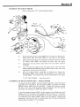
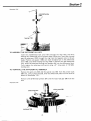
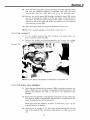
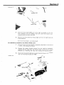
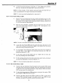
TO REMOVE THE KOHLER ElUGllVE
1.
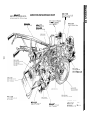
Refer t o illustration "B 1 " unless otherwise stated.
la.
Disconnect the throttle control (569) from the engine by releasing the
small clamp bolt and cable clamp on the side of the engine.
Ib.
Slacken the jubilee clip on the carburettor induction elbow end of the
air cleaner hose (595), and remove the hose from the elbow.
Ic.
Disconnect the stop switch cable (573) from the engine mounted
condenser.
Id.
Turn off the fuel supply from the petrol tank a t the fuel filter
bowl, and disconnect the pipe from the tank. Drain off any fuel in the
pipe before removing from the engine.
le.
With the engine suitably supported (on blocks etc.), remove the
8-setscrews (558) from around the perimeter of the clutch bell
housing (556). The machine may then be moved clear of the engine.
TO FIT THE ENGl NE
-
See instruction 6.
TO REMOVE THE DRIVE ADAPTOR (551)'- KOHLER ENGINE
To remove the drive adaptor from the engine crankshaft, remove the square
plug (557) from the side of the bell housing (556), and loosen the square
headed setscrew (554) using an extended k" square box spanner through
the hole in the side of the housing. Slide the adaptor from the housing,
and retain the locating key (555) (and spacer if fitted).
I f the drive adaptor bearing (553) is to be renewed, the old bearing may be
pressed out from the back of the adaptor, with the aid of a 1" dia. drift.
The new bearing can then be pressed into its location, greased, and secured
by positioning the special washer (552) over the bearing (domed side
outermost), and with the aid of a small punch, burr the lip of the bearing
housing over the washer in 3 or 4 places.
Section B
TO REMOVE THE BELL HOUSING (556) - KOHLER ENGINE
Having removed the drive adaptor as previously described, remove the
4-setscrews (560) and spring washers (561) from inside the bell housing,
thus allowing the bell housing t o be removed from the engine.
TO FIT THE BELL HOUSllVG (556) - KOHLER ENGINE
Position the bell housing qgainst the engine crankcase (with the plug hole
to the left), and secure using the 4-setscrews (560) and spring washers (561),
located inside the housing.
TO FIT THE DRIVE ADAPTOR (551) - KOHLER ENGINE
With the clutch bell housing in position, slide the spacer (when fitted)
onto the engine crankshaft and up to the engine casing.
Position the locating key (555) in .the slot in the engine crankshaft, and
slide the drive adaptor into position.
Using an extended ,%"square box spanner through the hole in the side of
the bell housing, tighten the square headed setscrew which secures the drive
adaptor to the engine crankshaft. Replace the plug in the side of the bell
housing.
TO REMOVE THE HAT2 ENGINE
1.
Refer to illustration "82" unless otherwise stated.
la.
Disconnect the large fuel pipe from the injection pump on the engine.
NOTE
Once this fuel line is disconnected, the fuel in the tank will drain out
due t o gravity, and suitable precautions should be taken.
Section B
-
Ib.
Disconnect the small injector spill pipe from the engine.
Ic.
Disconnect the throttle cable clevis (626) from the engine,
and having removed the 2-bolts (630) from the throttle
bracket (629), move the cable assembly aside.
Id.
Release the engine starting handle from the spring clip
(619) and withdraw the handle from the main frame tube.
le.
With the engine suitably suppor-red (on blocks etc.), remove
the 8-setscrews (617) which secure the bell housing t o the
gearbox flange, and retain the spring clip (619).
The machine may then be moved clear of the engine.
TO FIT THE ENGINE - See instruction 6.
TO REMOVE THE BELL HOUSllVG (616) - H A T 2 ENGINE
Remove the 10 setscrews (620) and 2-bolts (622) which secure the bell
housing to the engine, and hence remove the housing.
TO REMOVE THE DRIVE ADAPTOR (611) - H A T 2 ENGINE
Remove the bell housing as previously described, then remove the
6-setscrews (614) and spring washers (615) which secure the drive
adaptor to the engine. If the drive adaptor bearing (613) is to be
renewed, the old bearing may be pressed out from the back of the
adaptor, with the aid of a 1" dia. drift. The new bearing can then
be pressed into its location, greased, and secured by positioning
the special washer (612) over the bearing (domed side outermost),
and with the aid of a small punch, burr the lip of the bearing
housing over the washer in 3 or 4 places.
TO FIT THE DRIVE ADAPTOR (611) - HATZ ENGINE
Place the drive adaptor against the engine flywheel, and secure in
position using the 6-setscrews (614) and spring washers (615).
TO FIT THE BELL HOUSING (616) - HATZ ENGINE
With the drive adaptor in position, locate the bell housing against
the engine so that the 2-bolts (622) are positioned a t the top.
Secure the be1l housing using these 2-bolts (622) and the 10-setscrews
(620).
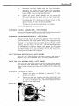
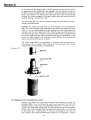
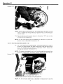
TO REMOVE THE ElVGllVE CLUTCH
Illustration '8.3:
2.
Remove the engine as described in instruction "1"
proceed as follows :
then
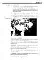
2a.
Remove the split pin from the end of the clutch shaft, and
while restraining the clutch using a flat bladed screwdriver,
as shown in illustration "B3", remove the special nut from
the end of the clutch shaft.
Section B
2b.
Remove the spacer (fitted to double plate clutches only),
and hence remove the clutch plate assembly by holding the
clutch operating arm back in the "disengaged position",
and using a soft headed hammer, tap the end of the shaft.
This will release the clutch assembly from the splines on the
clutch shaft.
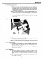
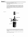
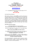
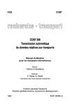
TO DISMANTLE THE CLUTCH UNIT (Refer to illustration "B4" unless otherwise stated).
If possible, mount the clutch unit on an old drive adaptor, which
should be clamped upright in a vice as shown in illujstration "B5",
as i t will make dismantling easier.
Illustration 'B4'
distance pieces (75)
clutch plate
*.+*,.,
+-%
*
I
.
clutch thrust
plate (71)
clutch plate fixed (77)
friction discs (78)
0
*
clutch plate
loose (79A)
Illustration '8.5'
.
Y
*
Section B
Remove the locking wire from the 4 special bolts (73); and so remove thkse
bolts.
The individual components may now be removed in the following order:
Clutch thrust plate (71), distance pieces (75) and springs (76), clutch plate
fixed (77), disc (78) 2-friction discs and 1-loose plate (79A) ( i f of the double
plate version), and lastly the bottom loose plate (79).
TO ASSEMBLE THE CLUTCH U N l T (refer t o illustration "B.4" unless o:herwise stated)
.Assembly of the clutch unit i s the reverse of the dismantling procedure
When fitting the friction disc(s), check that the plates are central. F i t the
4 special bolts (73) and tighten evenly to a torque of 31 Ibslft. (4.2 k g ' l ~ t i .
Secure the special bolts using a new piece of 12" long 16 swg locking 1:dlrct.
TO FIT THE CLUTCH UNlT
-
See instruction 5
TO REMOVE THE CLUTCH SHAFT
Special
remove
broken
behind
will be
note: I t is not necessary t o dismantle the gearbox Ir! urder t:?
the clutch shaft or the driving pinion, orov~dedthe shaft i s not
inside the gearbox. I n cases where the shaft i s broken at a uoint
the thread, a clutch shaft puller, special too!S.l(sc?esectio1.1 A ? ,
required.
Alternatively it may be possible t o weld a stud onto t h e front of the
shaft, so that the same method of removal may be used as for an unbroken
shaft, and this method of removal is described below. Should the clutch
shaft be broken within the gearbox, see section "C" ~nstruction "7"
for an alternative method of removal.
3.
Remove the engine and engine clutch as previously descrhed in
instruction "1" and "2", then proceed as follows:
3a.
Drain the oil from the gearbox (a container of at least 6 pints
capacity will be required).
3b.
Remove the special oilseal and the clutch thrust sleeve from inside
the clutch housing.
NOTE:
The oilseal may have t o be levered from the flange, as i t will
have been sealed t o the gearbox using "Hermatite".
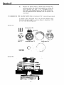
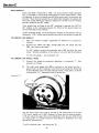
3c.
Remove the gearbox top inspection cover and with a pair of right
angled circlip pliers, remove the 2" internal circlip from the pinion
bearing housing as shown in illustration B6.
I t may be necessary to gently tap the end of the clutch shaft
NOTE:
using a soft headed hammer, until the bearing i s clear of the circlip. The
"ears" of the circlip should be a t the top of the housing; if not, turn the
circlip into this position. The circlip on removal from i t s location will not
drop into the gearbox, but will remain suspended on the clutch shaft.
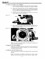
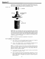
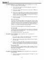
3d.
Place a 3%" long piece of 2%" 0.d. tubing over the end of the clutch
shaft, and by means of washers, and the clutch securing nut on the
thread of the clutch shaft, draw the shaft out in stages as shown in
illustration "B7a" adding more washers as necessary until the bearing
releases from its housing.
NOTE:
It may be necessary to prevent the clutch shaft from turning
by inserting a suitable bar through the gearbox top inspection hole and into
the crownwheel and pinion teeth.
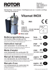
Section B
Illustration '6.6'
(The gearbox cover and internal components have been removed
for the purpose of this photograph only.)
Illustration 'B.7a'
ustration '6.7b1
Section B
Alternatively, where the shaft is broken a t a point behind the thread,
position the tube part of special puller S.l (see Section A special tools)
over the clutch shaft, as shown in illustration B7b, and secure by tightening
the two square headed setscrews. Then the shaft may be withdrawn by
screwing in the two setscrews on the flat, front face of the puller.
NOTE:
The special clutch shaft puller should not be used in cases
where the same clutch shaft is to be replaced, as the square headed setscrews may score the shaft which would cause the clutch thrust sleeve
to seize during operation.
3e.
Withdraw the shaft, complete with the thrust race, circlip and
bearing, through the oilseal aperture in the clutch housing.
The circlip will need to be compressed with a pair of circlip pliers
before it will pass through into the clutch housing.
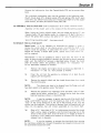
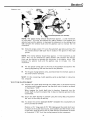
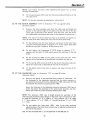
TO REMOVEIFIT THE CLUTCH SHAFT BEARING
To remove the bearing from a clutch shaft where the drive pinion i s a
separate component to the shaft; proceed as follows:
Remove the split pin and special nut from the front of the pinion, and using
a workshop press, push the shaft from the pinion and bearing as shown in
illustration "B.81r
To reassemble: The shaft can be pressed into the bearing, and the pinion
replaced and secured by the special nut and split pin.
To remove -the bearing from a clutch shaft where the drive pirrion is an
integral part of the shaft; proceed as follows:
Working from -the back of the pinion, carefully support the outer cup of
the bearing, and using a workshop press, push the shaft from the bearing
as shown in illustration "B9". The shaft can then be pressed through the new
bearing, until the bearing i s against the shoulder a t the back of the drive
pinion.
Illustration 'B9'
Illustration 'B8'
9-tooth pinion
a
clutch shaft and integral
7-tooth in ion
TO FIT THE CLUTCH SHAFT
4.
Position the clutch shaft assembly through the oilseal hole in the
clutch housing, allowing the pinion end of the shaft t o drop slightly
t o avoid the clutch operating pawl.
4a.
Place the retaining circlip on the clutch shaft, and using a pair of
circlip pliers, ease the circlip through the oilseal hole in the clutch
housing and allow it to slide up t o the pinion.
4b.
Using a soft headed hammer, tap the end of the clutch such that the
bearing slides into i t s location.
NOTE:
When tapping the bearing into i t s location, frequently turn the
clutch shaft by hand, t o ensure that the pinion does not become jammed in
the crownwheel.
4c.
Using a pair of right angled circlip pliers through the gearbox top
inspection hole, secure the clutch shaft bearing in its housing using
the circlip already suspended on the shaft.
4d.
Use the "tube method" described in instruction "3d" t o pull the
bearing back against the circlip. The crownwheel to pinion backlash
can not be checked until the clutch unit has been fitted.
4e.
Slide the thrust bearing onto the clutch shaft and up to the operating
pawl.
4f.
Smear a small amount of "Hematite" around the locating flange of
the special oilseal. F i t the oilseal (together with the thrust sleeve) and
secure in position using the 3-setscrews.
4g.
Refill the gearbox with 6-pints (3.4 litres) of good quality SAE 90
gear oil, and refit the top inspection cover with the trough towards the
pinion.
TO FIT CLUTCH UNIT
5.
Position the clutch unit on the clutch shaft and slide up to the thrust
sleeve, ensuring that the peg on the clutch thrust plate i s positioned t o
the side of the raised section of the thrust sleeve. This ensures that the
thrust sleeve rotates in the special oilseal during operation.
5a.
Slide the spacer onto the clutch shaft (double plate clutches only), and
secure the assembly using the special nut and split pin. When tightening
the clutch retaining nut, the clutch unit should be restrained from
turning using a large flat bladed screwdriver.
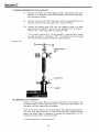
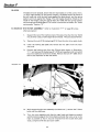
To check the crownwheel t o pinion backlash
NOTE: Because the crownwheel to pinion backlash can only be accurately
checked using a dial t e s t indicator, when the gearbox is dismantled, the
following method of assessing the backlash should only be used as a guide.
Locate the pointed special tool S.7 (see section 'A') over the clutch shaft and
clutch unit securing bolts, and secure in position using 2 " BSW nuts. Use a
suitdble bar through the gearbox top inspection hole to jam the crownwheel
and prevent its rotation. Rotate the clutch unit backwards and forwards, and
mark the furthest points of movement of the special tool, as shown in
illustration B10. 'The distance between these marks should be approx. 1
(3 mm) when the backlash is correct. I f incorrect, the backplate and chaincase
assembly must be removed so that shim may be added between the jackshaft
housing and the jackshaft bearing ( t o decrease rhe backlash), or gaskets added
between the jackshaft housing and the gearbox case ( t o increase the backlash).
The backplare and chaincase assembly should then be replaced and secured,
and the backlash rechecked.
"
Section B
TO FIT THE ENGINE
6.
When refitting .the engine, engage reverse gear or secure the handle bar
clutch lever in the "up" position, as this will hold the engine clutch unit
in the disengaged position, and will allow free movement of the clutch
disc(s) when aligning the drive adaptor pins with the holes in the friction
disc(s).
To fit the Kohler engine (refer to illustration 'BI' unless otherwise stated)
6a.
Support the engine in position such that the drive adaptor pins locate in
the engine clutch, and with the bell housing location holes in line with
those in the gearbox flange, secure the bell housing t o the gearbox using
the 8-setscrews (558). Tighten these setscrews t o a torque of 10 Ibslft.
( 1-3 kglm).
DISENGAGE REVERSE GEAR BEFORE CONTlNLllNG
6b.
Fit the stop switch cable (573) t o the engine mounted condenser.
6c.
Fit the air cleaner hose (595) t o the induction elbow and secure using the
jubilee clip (594).
6d.
Reconnect the throttle control (569) t o the engine using the small clamp
bolt.
6e.
Reconnect the fuel pipe (585) t o the engine, and the fuel filter bowl, and
"turn on" the petrol.
N0TE:Before starting the engine, check that the oil level in the engine sump i s
correct (see engine handbook).
Section B
To fit the Hatz engine (refer to diagram "62" unless otherwise stated)
6a.
Support the engine in position such that the drive adaptor pins locate in
the engine clutch, and with the bell housing location holes in line with
those in the gearbox flange, secure the bell housing to the gearbox using
the 8-setscrews (617).
Tighten the setscrews t o a torque of 10 Ibslft (1.3 kglm).
NOTE: The handleclip (619) is secured to the gearbox flange using one of the
setscrews (6 17).
DISENGAGE REVERSE GEAR BEFORE CONTINUING
6b.
Reconnect the injector spill pipe to the engine using the small banjo bolt,
with a gasket washer between the pipe and the engine and between the
bolt head and the pipe.
6c.
Reconnect the fuel line t o the fuel pump on the side of the engine using
a gasket washer each side of the pipe, and bleed the fuel system as
described in the engine manufacturers handbook.
6d.
Position the throttle bracket (629) against the side of the engine and
secure using the 2-bolts (630).
6e.
Reconnect the throttle cable clevis (626) t o the speed control lever on
the engine.
NOTE: Before starting the engine, check that the oil level in the engine sump
is correct (see engine handbook).
ADJUSTMENTS
Engine
Adjustments to the engine should be made as described in the engine
manufacturers handbook.
Engine clutch
Adjustment of the engine clutch is achieved by turning the wing nut on the
end of the clutch control rod.
To tighten the clutch, i.e. to stop it from slipping and adjust for normal wear:
the wing nut should be unscrewed.
To slacken the engine clutch, i.e. when i t does not disengage properly: the
wing nut should be screwed up.
When correctly adjusted there should be 6 " - %" of free movement a t the
operating lever (engine end of clutch rod).
Engine air cleaner
Both the Hatz and the Kohler engines use an oil bath type of air cleaner
assembly, which should be cleaned daily and refilled with fresh oil. Check
to ensure that the sealing surfaces are not damaged in any way. The air
cleaner i s one of the most important parts of the engine, and if correct
servicing i s carried out, will help prolong the life of the engine.
Section C
CONTENTS
Subject
Action
Page
AXLE BEARING STOP
Fitting
Removal
Fitting
Removal
34
21
31
CLUTCH SHAFT ASSEWIBLY
CLUTCH SHAFT PINION
BEARING
DIFFERENTIAL ASSEMBLY
DIFFERENTIAL LOCK
GEARBOX COVER
JACKSHAFT ASSEMBLY
LAYSHAFT ASSEMBLY
REVERSE IDLER GEAR
ROAD WHEELS
27
Fitting
Removal
Assemble
Dismantle
Assemble
Dismantle
Fitting
Removal
Assemble
Dismantle
Fitting
Removal
Assemble
Dismantle
Fitting
Removal
Fitting
Removal
Description
Fitting
Removal
TYRES
WHEEL AXLE ASSEMBLY
Assembly
Dismantle
Fitting
Removal
WHEEL FRICTION CLUTCHES Fitting
Removal
SERVICE BULLETINS APPERTAIIVING TO THIS SECTION ARE:Bulletin No.
-.
-
TOOLS LIST
-
Date
-
-
NO. off
1
1
1
1
1
1
1
1
1
1
%" BSW BOXspanner
2'' BSW Ring spanner
2" BSW Open ended spanner
2" BSW Ring spanner
&" BSW Ring spanner
%" BSW Ring spanner
%" BSW Open ended spanner
;A" BSW Ring spanner
Pair 6" engineers pliers
Pair right angled internal circlip pliers
SPECIAL EQUIPMENT
Containerltray of a t least 6 pints capacity
Universal bearing puller (2-legged)
Self grip wrench
Dial t e s t indicator and magnetic stand
No. off
1
1
1
1
1
CopperIRawhide mallet
1 Ib. Ball pein hammer
Large screwdriver
Special tool S.2
Special tool S.6
Section C
ROAD WHEELS
Each road wheel, fitted with a 4.00 x 12, 2-ply traction tread pneumatic
tyre, is mounted on a hub which incorporates a friction clutch dev~ce.These
are adjusted, so that the wheels have sufficient grip t o pull the machine, but
will slip if they become jammed by an obstruction between the wheels and
the frame. Single wheels are fitted as standard on the 20" and 24" models,
and twin wheels on the 30" model.
Twin wheels may be fitted t o the 20" machines if required, but NOT to
24" models, as the chaincase prevents the fitting of the second wheel on
the left hand side of the machine.
Unless otherwise stated, all the illustration numbers in this section refer to
illustration "C25", which can be found a t the end of this section on page 36.
TO REMOVE THE WHEELS
With the machine suitably supported (on blocks etc.), proceed as
1.
follows:
l a . Remove the wheel nuts (84), springs (85) and the wheel hub disc
(88), and remove the wheel.
On 30" models, remove the extension hub (130) and then the inner
wheel. Removal procedure is the same for left and right hand wheels.
To refit the wheels - see instruction 16.
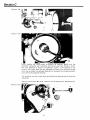
TO REMOVE THE WHEEL HUBS
2.
Remove the wheels as previously described in instruction 'I',then
proceed as follows:
2a.
The right hand wheel hub (89) is secured t o the wheel axle by a
special hub nut (87). Removal of this hub nut will allow the wheel hub
to be withdrawn from the axle with the aid of a 'hub puller', as shown
in illustration "C1" (see special tool S2 section A).
"C.
The left hand wheel hub (118) is secured to the wheel axle by a split pin
(121) and a special nut (120). Removal of these and the backing washer
(119) will allow the wheel hub t o be withdrawn from the axle with the aid
of a 'hub puller' in a similar manner t o that shown in illustration "C1" (see
special tool S2 section A).
To refit the wheel hubs - see instruction 15.
Section C
TO REMOVE T H E AXLE BEARING STOP (115)
Drain the oil from the gearbox (a container of a t least 6 pints capacity will
be required). Remove the left hand wheel and hub as previously described in
instructions 1 and 2, then proceed as follows:
3.
Remove the 4-setscrews (117) and spring washers ( 116) which secure
the bearing stop t o the main gearbox casing.
NOTE: The oilseal ( 113) should always be renewed before refitting the
bearing stop.
To refit the axle bearing stop - see instruction 13.
TO REMOVE T H E GEARBOX COVER (24)
4.
Drain the oil from the gearbox (a container of a t least 6 pints capacity
will be required). Remove the right hand wheel and hub as previously
described in instructions 1 and 2. Remove the starting handle, then
proceed as follows:
4a.
Remove the setscrews (22) and spring washers (23) from the starter
dog bearing housing (21), and remove the housing complete with its
gasket and starter dog ( 19).
4b.
Remove the setscrews (26) and spring washers (27) from around the
perimeter of the gearbox case.
4c.
With the aid of a flat bladed screwdriver, prise the gearbox cover from
the main gearbox casing.
The cover is located on 2-dowel pins, and may be difficult t o move a t
first.
Reverse idler gear assembly
-
to remove.
Having removed the gearbox cover as previously described, proceed as
follows:
Remove the 1/2" BSF philidas nut (38) and the flat washer from the reverse
idler pin (34).
Withdraw the idler pin from i t s location in the gearbox cover, complete with
the reverse idler gear (35).
If the idler gear bush (36) is t o be replaced, it should be pressed out with the
aid of a %" dia. soft brass drift. The' new bush may then be pressed into the
reverse gear until flush with the gear faces. Two 2" dia. oil holes should then
be drilled in the bush, working through the existing holes in the idler gear.
The bush will then have t o be reamed to a diameter of 0.627"/0.629" to
remove the burrs caused by drilling, and to ensure correct bore size.
Reverse idler gear assembly - t o f i t
Insert the idler pin (34) through the idler gear (35) so that the smaller
12-tooth gear is against the head of the pin. Locate the pin in the gearbox
cover, and secure using the flat washer (37) and philidas nut (38).
Wheel axle oilseal (90)
The wheel axle oilseal, located in the gearbox cover, should be removed
before refitting the cover t o the main gearbox case, so that a new oilseal may
be used on assembly. The old seal may be pressed out with the aid of a
2 2 " dia. drift.
To refit the gearbox cover
-
see instruction 14.
Section C
T O REMOVE THE WHEEL AXLE ASSEMBLY
5.
Having removed the wheels and hubs, axle bearing stop and gearbox
cover as previously described in instructions 1-4, proceed as follows:
5a.
Remove the retaining split pin from the differential lock control
quadrant pivot pin and slide the pivot pin out of the control quadrant
as far as possible and remove the locknuts and trunnion (shown in
illustration "(22") from the differential lock selector.
5b.
Remove the split pin (40) and special nut (39) from the end of the
layshaft (50), and remove the bearing (41).
Illustration "C.2"
5c. While supporting the axle by hand, tap the axle assembly from i t s
location in the main gearbox casing, using a soft headed hammer as
shown in illustration "C3".
Illustration
(The engine has been removed for the purpose of this photograph only)
NOTE: On removal of the axle assembly, the differential lock selector will
also be removed from i t s location.
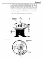
TO DISMANTLE THE AXLE ASSEMBLY
Remove the axle bearing (110) from the end of the axle shaft using a
universal bearing puller, as shown in illustration "C4", so that the differential
lock assembly may be removed.
TO DISMANTLE THE DIFFERENTIAL LOCK
Remove the locking wire (105) from the setscrews (104), and remove these
setscrews.
NOTE: The differential lock assembly will fall apart on removal of these
setscrews, and care should be taken to avoid losing the 3-spacers (106).
Section C
Illustration "C4"
TO ASSEMBLE THE DIFFERENTIAL LOCK
Insert the 3-differential lock pins (107) through the ring (103), and while
holding the differential pins to prevent them falling out, invert the ring and
pass the setscrews (104) through the ring from the opposite side to the pin
heads. Position one spacer (106) over each threaded hole in the differential
lock (108), and while holding the ring (103) in position over the differential
lock, screw the setscrews through the spacers and into the differential lock.
Fully tighten the setscrews and secure using a 9" long piece of 16 SWG
locking wire.
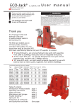
TO 31SMANTLE THE DIFFERENTIAL ASSEMBLY
Remove the split pins (93) and the special nuts (92) from the pinion studs
(99) and, using a piece of wood, lever the differential plate from the studs as
shown in illustration "C5".
Remove all 6 differential pinions (97) and the loose hub gear (96) from the
axle.
Illustration "C5"
pinion studs (99)
differential plate
bull
/
Section C
If the loose hub gear bearing (91) i s to be replaced, a special tool S3, similar
in appearance to the differential lock assembly, will be required in order t o
be able to press the bearing from i t s location. Using the special tool S3 (see
special tools section 'A') working from the back face of the loose hub gear
through the holes provided in the gear flange, press the bearing from i t s
location as shown in illustration "C6".
The loose hub gear can then be pressed through the new bearing using an
ordinary workshop press.
Withdraw the wheel axle and fixed hub rivet assembly from the bullwheel
(98). The fixed hub gear (100) i s secured to the wheel axle flange by 6 rivets
(102). If for any reason these rivets are removed, the new rivets should be
inserted from the axle flange side of the fixed hub gear, and burred over on
the fixed hub gear side. The burrs must then be ground flat to prevent them
fouling the loose hub gear when the differential unit is reassembled. If the
pinion pins (95) located in the differential plate (94) are to be replaced the
new pins should be burred over to secure.
The pinion studs (99) in the bullwheel, if replaced, must have the burred
ends ground flat to prevent them fouling on the small gear (44), on the
layshaft (50) when the gearbox is reassembled.
Illustration "C6"
head
!
-
special tool
'S3'
TQ ASSEMBLE THE DIFFERENTIAL UNIT
Position the wheel axle and fixed hub gear rivet assembly through the
bullwheel (98)) from the differential pinion stud side, such that the fixed
hub gear locates in the centre of the bullwheel (as shown in illustration"C7").
Locate one differential pinion (97) on each pinion stud on the bullwheel.
Position the loose hub gear (96), complete with bearing (91), over the end
of the wheel axle, checking that it is free to rotate against the fixed hub
gear. Position the remaining differential pinions on the bullwheel as shown
Section C
in illustration "C8". such that they mesh with the fixed hub gear, the
existing differential pinions and that they are positioned over their respective
pinion pin location holes. Invert the differential plate (94) and fit t o the
bullwheel such that -the pinion pins (95) locate through the differential
pinionsand into the bullwheel. Tap the plate to fully locate, and secure using
the special nuts (92) and split pins (93). Slide the differential lock assembly
onto the wheel axle and check that it engages in the fixed and loose hub
gears. With the aid of a piece of 1%" ID. tubing, tap the bearing (11) onto
the end of the axle shaft.
To ref it the axle assembly into the gearbox
Illustration "C7"
fixed hub gear
rivet assembly
\
Illustration "C8"
,
-
see instruction 1 2.
Section C
TO REMOVEIDISMANTLE THE LAYSHAFT
6.
Remove the wheels and hubs, gearbox cover, axle bearing stop, axle
assembly, top inspection cover and the dipstick as previously described,
then proceed as follows:
6a.
Remove the bull pinion (43), small gear (44) and spacer (46) from the
layshaft, and retain any shims which may have been fitted.
6b.
Remove the bearing stop (54) from the gearbox casing, and while
supporting the layshaft by hand, tap the layshaft from i t s location.
Remove the medium gear (48) and large gear (49).
If the layshaft bearing (51) is t o be renewed, a universal puller should
be used as shown in illustration "C9". The shaft can then be pressed
into the new bearing using an ordinary workshop press.
Illustration "C9"
bearing
bearing (51)
layshaft
TO ASSEMBLE THE LAYSHAFT
Position the large gear (49) and medium gear (48) on the layshaft. The
combined width of these gears should be 1". Add shims (47) between the
two gears until this measurement i s achieved.
Position the spacer (46) on the layshaft against the medium and large gears.
The small gear (44) should be 'h" wide, and shims (45) should be placed
against the spacer (46), as necessary to achieve this measurement. Fit the
small gear and bull pinion onto the layshaft.
To refit the layshaft.- see instruction 1 1.
Section C
-
TO REMOVE THE CLUTCH SHAFT
7.
I f the clutch shaft i s to be removed without dismantling the gearbox
follow the method described in section '6' instruction 3.
However, if the clutch shaft is broken and the gearbox has to be
dismantled, check that the engine and engine clutch (see section 'B'),
gearbox cover, wheel axle and layshaft assemblies have all been removed,
then proceed as follows:
7a.
Remove the special oilseal (68) and thrust sleeve (66) from the clutch
housing, and slide the thrust bearing (65) from the shaft.
7b.
Remove the circlip (63) from the pinion bearing housing, and using a
self grip wrench, remove the shaft as shown in illustration "C10".
Illustration '
To remove the pinion bearing
To remove the bearing from a clutch shaft where the pinion i s a separate
component to the clutch shaft, proceed as follows:
Remove the split pin and special nut from the front of the pinion and using
a workshop press, push the shaft from the pinion and bearing as shown in
illustration "C1 1 ".
To reassemble: The shaft can be pressed into the bearing, and the pinion
replaced and secured by the special nut and split pin.
To remove the bearing from a clutch shaft where the drive pinion i s an
integral part of the shaft proceed as follows:
Working from the back of the pinion, carefully support the outer cup of the
bearirlg, and using a workshop press, push the shaft from the bearing as shown
in illustration "C12':
To reassemble: The shaft can be pressed through the new bearing until it is
against the shoulder a t the back of the pinion.
To refit the clutch shaft - see instruction 10.
Section C
Illustration "C11"
Illustration "C12"
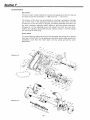
TO DISMANTLE/REMOVE THE JACKSHAFT
8.
Remove the engine and engine clutch (see section 'B'), wheels and hubs,
gearbox cover, wheel axle assembly, layshaft assembly and clutch shaft,
then proceed as follows:
8a.
Remove the bolts (160) which secure the rotor dog clutch selector
housing t o the jackshaft housing (shown in illustration "C13") and
move the selector housing aside.
.& <
securing bolts (160)
Section C
8b.
Remove the starter dog bearing (18) from the end of the jackshaft (1'2)
and remove the special circlip.
8c. Slacken the retaining screw on the reverse gear selector arm, shown in
illustration "C14" and remove the arm and joint block, taking care to
retain the locating key.
Illustration
"C14"
ad
8d.
--
selector arm
Remove the selector bush (3A) and withdraw from the gearbox the
reverse selector together with the single pinion (17).
NOTE: Shims may be fitted t o the reverse selector, if so they should be
retained as -they may be required on assembly.
8e.
Slacken the speed change selector arm retaining screw, shown in
illustration "C14" and remove the arm and joint block, taking care to
retain the locating key.
8f.
Remove the selector bush (3) and slide the double pinion (16) from the
jackshaft together with the speed change selector.
NOTE: Shims may be fitted to the speed change selector, if so they should
b e retained as they may be required on assembly.
8g.
Illustration '
Using a hammer, and a soft brass drift -through the rotor dog clutch
selector housing, tap the jackshaft from i t s location as shown in
illustration "C15".
The jackshaft may then be removed from the
gearbox together with the rotor clutch dog and shims.
Section C
The bearing ( 1 I)may be partially removed from the jackshaft with the aid'of
special tool S.6 (see section 'A') as shown in illustration "C16". The bearing
may then be removed completely using a universal beariug puller.
Illustration "C16"
Special note: The crownwheel (13) is secured t o the jackshaft (12) by 6-rivets
(14). If the rivets are removed, the new rivets should be inserted from the
crownwheel side, and burred over on the jackshaft flange. These burrs should
then be ground flat t o prevent them from fouling the gearbox casing on
reassembly. The new bearing may then be pressed onto the jackshaft with
the aid of a piece of 1 ,k" I D. tube.
NEXT: Fitlassemble the jackshaft as described in instruction 9.
TO FIT/ASSEMBLE THE JACKSHAFT
9.
Place 2-shims (10) onto the jackshaft against the bearing (11). Slide the
rotor clutch dog onto the jackshaft and up t o the shim.
9a.
Using a soft headed hammer, tap the jackshaft and bearing into i t s
location in the gearbox casing, as shown in illustration "C17".
NOTE: I t is advisable to fit the clutch shaft a t this stage so that the correct
crownwheel to pinion backlash may be achieved. To fit the clutch shaft and
adjust the backlash, refer to instructions 10 to 10c inclusive. When the
backlash is correct, proceed as follows:
9b.
Fit and secure the rotor dog clutch selector housing, using the bolts
(160) shown in illustration "C13."
9c. Slide the double pinion (16) onto the jackshaft, small gear first. Fit the
speed change selector (29), such that the selector block locates in the
double pinion and in the gearbox case. Secure in position using the
selector bush (3).
Section C
Illustration "C17"
NOTE: The speed change selector should have approx. :,"free movement
up and down. This may be achieved by adding washers (31) between the
selector bush and the selector, t o decrease the movement, or by adding shims
(3B) between the selector bush and the gearbox case to increase the free
movement.
9d. Slide the single pinion (17) onto the jackshaft, gear side outermost. Fit
the reverse selector (30) such that i t locates in the groove in the single
pinion.
NOTE: The reverse selector should have approx. %;' free movement up and
down. This may be achieved by adding washers (31) between the selector
bush and the selector to decrease the movement, or by adding shims (38)
between the selector bush and the gearbox case to increase the free
movement.
9e.
Fit the special circlip (15) t o the end of the jackshaft and position the
starting dog bearing (18) over the end of the jackshaft.
9f.
Fit the gear change selector arms, and check that the interlock plates on
the arms function correctly.
NEXT: Fit the remaining clutch assembly parts as described in instruction
10c. onwards.
TO FIT THE CLUTCH SHAFT
10. Position the clutch shaft -through the oilseal hole in the clutch housing
and using a soft headed hammer, tap the shaft into its location as shown
in illustration "C18".
When tapping the clutch shaft into its location, frequently turn the
clutch shaft by hand t o ensure that it does not become jammed in the
cx-ownwheel.
10a. Secure the shaft bearing in position using the circlip (63), and position
the 'ears' of the circlip a t the top.
lob. To obtain the correct backlash (0.010") between the crownwheel and
pinion proceed as follows:
Position a 3%" long piece of 2%" OD. tubing over the clutch shaft and,
by means of the clutch securing nut, some washers and the thread on the
clutch shaft, draw the pinion out of mesh with the crownwheel as shown
in illustration "C19", until the circlip prevents further movement.
Section C
Illustration
While holding the clutch shaft t o prevent its rotation, gently turn the
jackshaft backwards and forwards, and using a dial test indicator, check
the total backlash as shown in illustration "C20". I f the backlash is not
correct, the clutch shaft and the jackshaft will have to be removed so that
shim may be added ( t o decrease backlash) or removed ( t o increase backlash)
from behind the jackshaft bearing.
The jackshaft and the clutch shaft should then be replaced and the backlash
rechecked.
Refer to instructions 9b. to 9f. inclusive, for the sequence of asserr~blingthe
jackshaft.
Section C
10c. Check that the clutch shaft bearing retaining circlip (63) has been fitted,
and that the jackshaft assembly is complete, then slide the thrust
bearing (65) onto the clutch shaft and up t o the operating pawl.
10d. Position the thrust sleeve (66) through the special oilseal (68) taking
care not to damage the rubber lip of the seal. Apply a small amount of
'Hermatiter around the locating flange of the oilseal. Locate the thrust
sleeve over the clutch shaft and secure the oilseal to the main gearbox
case using the 3-screws (69).
10e. Refit the engine clutch and engine as described in section 'B'.
NEXT: Fit the layshaft assembly as described in instruction 11.
TO FIT THE LAYSHAFT
11. Fit the layshaft bearing stop (54) complete with gasket ( 5 3 ) , and
secure using the 3-setscrews (56).
1la. Position the layshaft and bearing assembly, and using a soft headed
hammer, tap the assembly into i t s location as shown in illustration "C21".
Illustration
NEXT: Fit the wheel axle assembly as described in instruction 12.
TO FIT THE WHEEL AXLE ASSEMBLY
12. Check that the differential lock selector (109) i s straight and square, and
that i t slides freely in its location in the gearbox case. Remove from the
gearbox and position the fork in the slot in the differential lock
assembly.
12a. Position the axle assembly in the gearbox casing such that the differential
lock selector locates in the gearbox and the pins of the differential lock
locate through the back of the bullwheel.
While supporting the assembly, as shown in illustration "C22"
axle bearing into its location.
tap the
12b. With the aid of a piece of 1k," OD. tube, tap the bearing (41) onto the
end of the layshaft (50), and secure using special nut (39), and a split
pin.
Section C
stration
NOTE: When tightening the special nut, the layshaft gears should be jammed
using a suitable bar through the top inspection hole, so that the gears
cannot rotate.
12c. Fit the locknuts and trunnion shown in illustration "C2" and refit the
differential control quadrant.
NEXT: Fit the axle bearing stop as described in instruction 13, and the
gearbox cover as described in instruction 14.
TO F I T THE AXLE BEARING STOP (115)
13. Fit a new oilseal into the bearing stop, and using metal shim or tape t o
protect the oilseal against the wheel axle splines, slide the bearing stop
up to the gearbox case as shown in illustration "C23". Secure the
bearing stop using the 4-setscrews ( 1 17).
IVOTE: To prevent the possibility of an oil leak through the setscrews, they
should be coated with "Hermatite" before securing the bearing stop.
Illustration
(The engine has been removed for the purposo of this photograph only).
NEXT: Fit the left hand wheel hub as described in instructions 15 and 16.
34.
Section C
TO FIT THE GEARBOX COVER
14. Position the gearbox cover (24), against the gearbox casing so that the
starting dog bearing (18), layshaft bearing (41) ahd wheel axle bearing
(91) locate correctly. Tap the cover into position, and locate using the
2-dowel pins (28). Fully secure the cover using the setscrews (26) around
the perimeter of the gearbox.
NOTE: Fit the top inspection cover (5), with the trough towards the pinion,
to prevent foreign matter from entering the gearbox. Fit the oil dipstick.
14a. Fit a new oilseal (90) into the gearbox cover, using metal shim or tape
t o protect the oilseal against the splines on the loose hub gear as shown
in illustration "C24", and tap into position with the aid of a 1 " ID.
piece of tube.
Illustration 'C24'
14b. Fit the starter dog bearing housing (21) complete with the starting dog
(19), and secure using the setscrews (22).
NEXT: Fit the right hand wheel and hub as described in instructions 15 and 16.
TO FIT THE WHEEL HUBS
15. Position the left hand wheel hub (118) over the wheel axle and secure
using the washer (119) and special nut (120). Fully tighten the nut,
and lock using a split pin (121).
The right hand wheel hub (89) is secured by a special hub nut (87) which
should be fully tightened.
TO FIT THE WHEELS
16. Position the wheel over the spigot on the wheel hub, (if double wheels
are fitted, slide the extension hub over the wheel studs and up t o the
wheel centre then fit the second wheel over the spigot on the extension
hub).
16a. Fit the wheel hub disc (88) over the wheel studs, and secure with the
springs (85) and nuts (84).
Section C
WHEEL FRICTION CLUTCHES:
Tighten the wheel nuts so that the springs are fully compressed, then slacken
back each nut half a turn. This will ensure that the safety clutch device will
operate correctly. Should the wheel hubs slip when the machine is in normal
use, tighten the wheel nuts evenly until sufficient grip is acquired to produce
forward movement of the machine.
TYRES:
Check that the tyre pressure is correct - 20 psi. (1.4 kg/sq,cm.), and that
the tyres are in good condition.
Adjustments to the gear selectors and the differential control, should be made
as described in section 'Dl, ADJUSTMENTS.
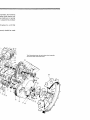
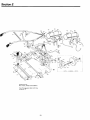
Illustration "C25".
Gearbox assembly, wheels and hubs.
Keep this page open when referring t o section C.
~mpressed,then slacken
;afety clutch device will
he machine is in normal
I is acquired to produce
.4 kg/sq,cm.), and that
:ontroll should be made
This illustration shows the twin plate clutch assembly
and clutch shaft with loose p~nion.
Section D
-
CONTENTS
Subject
Action
CLUTCH
CLUTCH COIVTROL ARM
Adjustment
Fitting
Removal
CLUTCH CONTROL ARM ROD Fitting
Removal
CLUTCH COIVTROL HAND
LEVER
Fitting
Removal
CLUTCH CONTROL PIVOT
LEVER ROD
Fitting
Removal
DIFFERENTIAL CONTROL
ARM
Fitting
Removal
DIFFERENTIAL CONTROL
ROD
Fitting
Removal
DIFFERENTIAL LOCK
Adjustment
D l FFERENTIALIROTOR
HAND CONTROL LEVER
Fitting
Removal
GEAR CHANGE CONTROL
TUBE
Fitting
Removal
GEAR CHANGE GATE
Fitting
Removal
GEAR CHANGE LEVER
Fitting
Removal
GEAR CHANGE ROD
Fitting
Removal
GEAR CONTROL QUADRANT Fitting
Removal
PIVOT LEVER ROD
Fitting
Removal
REVERSE INTERLOCK
Adjustment
Fitting
Removal
ROTOR DOG CLUTCH
Adjustment
ROTOR CONTROL ROD
Fitting
Removal
SERVICE BULLETINS APPERTAINING TO THIS SECTION ARE:
Bulletin No.
..-
-
TOOLS LIST
No. o f f
2
:4" BSW Open ended spanners
1
,',"BSW Open ended spanner
,'" BSW Open ended spanners
Pair 6" engineers pliers
2
1
1
1
1
Small punch
CopperIRawhide mallet
1 Ib-Ball pein hammer
Date
Page
43
42
42
40
40
Section D
Unless otherwise stated, all the illustration numbers in this section refer t o
diagram "Dl", which can be found at the end of this section on page 44.
DIFFERENTIAL CONTROL
To remove the differential control rod (417)
Remove the nut (421) and washer (422) from the eye bolt (420) on the end
of the control rod, and withdraw the eye bolt from its location.
Remove the split pin (4.18) from the rotor control rod block, and hence
remove the rod complete with the eye bolt and springs.
To remove the differential control arm (423)
Remove the differential control rod, then proceed as follows: remove the
split pin (425) from the quadrant pin (424),which acts as the pivot pin for the
control arm, and hence remove the pin and the control quadrant.
To f i t the differential control arm (423)
Position the differential lock selector quadrant over the differential lock
trunnion (426).
Slide the quadrant pin (424) through the main frame and into the quadrant
such that the split pin (425) may be inserted through the quadrant pin
between the main frame and the top of the quadrant.
To f i t the differential control rod (417)
Position the rod through the locating block on the rotor control rod, and
secure in position using split pin (418).
Position the eye bolt (420) in the differential lock selector quadrant and
secure using the flat washer and nut (421I.
NOTE: The securing nut should be fully tightened and then slackened back
approx. half a turn such that the eye bolt is able t o rotate under operational
conditions.
ADJUSTMENTS SHOULD BE MADE AS DESCRIBED AT THE END OF
THIS SECTION.
ROTOR CONTROL
To remove the rotor control rod (410)
Remove the split pin (418) from the differential lock selector control rod.
Withdraw the rod from the block and move aside.
Remove the nut (413) from the eye bolt (412) and hence remove the eye
bolt from the rotor control arm (414).
Remove the split pin (409) from the hand lever end of the rotor control rod
(410) and then remove the rod.
To f i t the rotor control rod (410)
Position the eye bolt (412) through the rotor control arm (414) and secure
using nut (413).
NOTE: The securing nut should be fully tightened and then slackened back
approx. half a turn, such that the eye bolt is free to rotate under operational
conditions.
Locate the top of the rotor control rod in the hand control lever (4061, and
secure using split pin (418).
Section D
CONTROL HAND LEVER
To remove the hand control lever (406)
Remove the split pin (409) from the rotor control rod (410), and move the
rod clear.
Remove the philidas locknut (408) and spring (407), and then remove the
hand lever from the gear control quadrant (405).
To fit the hand control lever (406)
Position the control lever over the threaded shaft on the gear control quadrant
(405).
Fit the spring (407) and nut (408) and tighten such that the spring holds the
hand lever securely in the notches in the gear quadrant.
Fit the rotor control rod-(410) to the hand lever, and secure using split pin
(409).
ADJUSTMENTS SHOULD BE MADE AS DESCRIBED AT THE END OF
THIS SECTION
GEAR CONTROL QUADRANT
To remove the gear control quadrant (405)
Remove the philidas locknut (408) and spring (407) from the hand control
lever, and move the lever aside.
Remove nut (399) and setscrew (398) and remove the handlebar positioning
arm (397).
Remove the split pin (404) from the positioning pin (401). Remove the
positioning pin and spring (402).
Remove the 2-setscrews which secure the control quadrant to the main
frame.
NOTE: These setscrews also secure the depth control skid socket.
To f i t the gear control quadrant (405)
Position the control quadrant on the main frame with the lug facing forward,
and secure using the 2-setscrews which also retain the depth skid socket.
Position spring (402) inside the quadrant and slide the positioning pin (401)
through the quadrant and spring, and secure using split pin (404).
Locate the positioning arm (397) over the positioning pin (401) and secure
the arm t o the quadrant using setscrew (398), washer (400) and philidas
locknut (399).
NOTE: The philidas locknut should be fully tightened and then slackened
back approx. half a turn, such that the positioning arm is free to move.
Locate the control hand lever (406) over the shaft on the gear control
quadrant, f i t spring (407) and nut (408), and tighten such that the spring
holds the hand lever securely in the notches in the gear quadrant.
ADJUSTNIENTS SHOULD BE MADE AS DESCRIBED AT THE END OF
THIS SECTION.
Section D
CLUTCt-I CONTROL
To remove the pivot lever t o control arm rod (440)
Remove the nut (443) from the eye bolt (442) on the clutch control arm
(445), and then remove the eye bolt.
Remove the split pin (439) from the control arm rod (440) a t the pivot
lever end.
To f i t the pivot lever t o control arm rod (440)
Locate the end of the rod through the pivot lever (436) and pivot lever rod
(434), and secure using the flat washer and split pin.
Position the eye bolt (442) through the control arm (445) and secure using
nut (443).
NOTE: The philidas locknut should be fully tightened and then slackened
back approx. half a turn, such that the eye bolt is free to rotate under
operational conditions.
To remove the hand lever to pivot lever rod (434)
Remove the split pin (439) from the control arm rod (440) a t the pivot
lever (436), and move the control arm rod aside.
Remoue the split pin (431) from the hand lever pivot pin (430), and remove
the pivot pin and rod.
To f i t the hand lever t o pivot lever rod (434)
Locate the control arm rod (440) through the pivot lever (4361 and position
the pivot lever rod over the control arm rod, and secure using the flat washer
and split pin.
Position the adjusting link (432) between the lugs of the hand lever, and
secure using the pivot pin (430) and split pin (431).
To remove the control arm (445)
Remove the locknut (443) from the control rod eye bolt (442) and move the
eye bolt and rod aside.
Slacken the setscrew (447) which secures the control arm to the clutch
operating pawl, and remove the control arm and locating key (446).
To f i t the control arm (445)
Position the control arm and locating key on the clutch operating pawl
spindle and secure by tightening setscrew (447).
Locate the control rod eye bolt (442) through the top of the control arm
and secure using locknut (443).
NOTE: The philidas locknut (443) should be fully tightened, and then
slackened back approx. half a turn, such that the eye bolt is free t o rotate
under operational conditions.
To remove the hand lever (428)
Remove thesplit pin (431) and pivot pin (430) from the adjusting link (432),
and move the pivot lever rod aside.
Section D
With the aid of a punch, remove the flat headed rivet (429) from the hand
lever, and then remove the lever. A new rivet (429) will be required when
refitting the hand lever.
To f i t the hand lever (428)
Position the hand lever on the handlebar, locate using the flat headed rivet
(429) (inserted from the left hand side of the handle bar) and burr the end of
the rivet into the countersunk in the lever.
Position the adjusting link (432) between the lugs of the hand lever, and
secure using the pivot pin (430) and split pin (431).
ADJUSTMENTS SHOULD BE MADE AS DESCRIBED AT THE END OF
THIS SECTION.
GEAR CHANGE CONTROL
To remove the gear lever and gate
Remove the 2-bolts which secure the gate (380) to the main frame, and
remove complete with the upper gear lever. Do not lose the gear lever spring
(378).
Remove the nut (388) from the 3rd and reverse gear control rod eye bolt
(387).
Remove the pivot bolt (381), and remove the lower gear lever.
To f i t the gear lever and gate
Locate the control rod eye bolt (387) through the gear lever and secure using
the nut (388).
Secure the gear lever to the flange on the 1st-2nd gear control tube using the
pivot bolt (381) and nut (383).
Position the upper gear lever through the gate (380), and with the spring
(378) located correctly in the upper lever, position over the lower lever and
secure the gate using the 2-bolts through the rear support bracket (384) and
into the main frame.
To remove the gear control tube (389) and rod (390)
Remove the gear lever, rear bracket (384) and stay rod (373), then proceed
as follows:
Slacken the retaining setscrews on the 3rd and reverse gear selector arm
(396) and using a screwdriver blade, lever the selector arm from i t s location.
NOTE: Retain the locating key (394) and the brass universal joint (395).
Slacken the retaining setscrew on the 1st-2nd gear selector arm (392) and
using a screwdriver blade, lever the selector arm from its location.
NOTE: Retain the locating key (394) and the brass universal joint (391).
The control tube and the rod can now be removed
To f i t the gear control tube and rod
Locate the rear bracket (384) and gate (380) against the main frame and
secure using the 2-bolts and nuts.
Section D
Locate the control rod and tube through the main frame and secure to the
rear bracket by inserting the threaded trunnion through the bracket and
secure using the flat washer and nut (385).
Position the upper gear lever (370) through the gate, and with the spring
(378) in position in the upper lever, position the two halves of the gear lever
together and checking that the control rod eye bolt (387) locates through
the lower lever, secure to the flange on the control tube (389) using the pivot
bolt (3811, washer and nut (383). Fit and tighten the eye bolt nut (388).
NOTE: The nut (388) should be fully tightened, then slackened back approx.
half a turn such that the eye bolt is free to rotate under operational conditions.
Check that the brass universal joint (391) slides freely on the 1st-2nd gear
selector arm (392) and on the control tube. If not, the location holes should
be reamed out as necessary to produce free movement. Locate the selector
arm through the universal joint and position the control tube through the
other hole. Position the selector arm over the gearbox selector shaft, and
locating on key (394), tap the selector arm onto the shaft, and tighten the
selector arm setscrew (393).
Fit the stay rod (373) between the main frame and the rear bracket, and
adjust i t s length using the 2-locknuts (374) such that there is approx. A' free
movement between the end of the control tube (389) and the main frame.
Check that the brass universal joint (395) slides freely on the 3rd-reverse gear
selector arm (396) and on the control rod (390). If not, the location holes
should be reamed out as necessary to produce free movement. Locate the
selector arm through the universal joint and position the control rod through
the other location hole. Position the selector arm over the gearbox selector
shaft, and locating on key (3941, tap the selector arm onto the shaft, and
tighten the selector arm setscrew (393).
ADJUSTMENTS SHOULD BE MADE AS DESCRIBED AT THE END OF
THIS SEC1-IOIV.
REVERSE INTERLOCK MECHANISM
To remove the reverse interlock
Remove the nut and setscrew (451) from the base of the interlock vertical
link (4531, and remove the link.
Remove the split pins (450) from both ends of the rocker pin (449).
Withdraw the rocker pin and remove the rocker (448).
Remove the nut (457) and flat washer from the rod (454), and remove the
spring, flat washer and rod.
To f i t the reverse interlock
Position the rocker (448) between its location 'points in the main frame, such
that the lever part locates under the reverse gear selector arm (396). Slide the
rocker pin (449) through the rocker and main frame, and secure either end
using a split pin.
Secure the vertical link (453) to the rocker using the setscrew (451) and nut.
Locate the rod (454) through the main frame and twist such that it locates
in the vertical link. Position a flat washer (455), spring (456) and flat washer
(455) over the rod, and secure using the locknut (457).
ADJUSTMENTS SHOULD BE MADE AS DESCRIBED AT THE END OF
THIS SECTION.
Section D
ADJUSTMENTS
Clutch adjustment
The clutch should be adjusted t o give ,$" - %" (5-6 mm) free movement a t
the clutch operating arm (445). Adjustments should be taken up a t the
control arm, by means of the wing nut (444).
NOTE: If the clutch slips during operation, the control rod wing nut should
be LINSCRE\NED. I f the clutch does not disengage properly, the wing nut
should be screwed further onto the rod. Final adjustment should be checked
with the machine under operational conditions, and further adjustment made
as necessary.
Gear selector control adjustment
The speed change and reverse selectors located in the gearbox, should have
approx. A" free movement up and down. This may be achieved by adding
washers (C1-31) between the selector bush and the selector, t o decrease
movement, or by adding shim (C1-38) between the selector bush and the top
of the gearbox case t o increase free movement.
Check that the brass universal joint blocks slide freely on the selector arms
and the control rodltube. I f tight, ream as necessary t o provide a close sliding
fit. I f loose, replace the joint blocks.
Check that the 3rd-reverse gear control rod (01-390) is free t o move inside
the 1st-2nd gear control tube (Dl-389), if not, free and lubricate.
Support the machine such that the wheels are clear of the ground, and secure
the engine clutch in the disengaged position.
To adjust 1st-2nd gear controls: while turning over the gearbox internals, by
meansof the starting handle, adjust to give neutral a t the mid gate position by
bending the control tube rod, ( i f necessary). Check that 1st-2nd gears are
obtainable, and that they engage fully.
To adjust 3rd-reverse gear control: while turning over the gearbox internals,
by meansof the starting handle, adjust t o give neutral at the mid gate position
by screwing in or out the control rod ( D l - 3 9 0 ) .Check that 3rd-reverse gears
are obtainable, and that they engage fully.
Check that the selector arm interlocks are not bent, and that they function
correctly, i.e. that two gears cannot be selected at the same time.
Check that the selector arm securing setscrews are tight, then lower the
machine t o the ground and release the engine clutch.
To adjust the reverse interlock: Lift the clutch hand lever and select reverse
gear. The interlock vertical link should rise and prevent the hand lever from
returning t o the engaged position. ( I f the vertical link is worn, replace). Press
down on the hand lever and check that the clutch engages: adjust the length
of the spring (456) as necessary, by means of the locknut (457).
Lift the hand lever and return the gear lever t o the neutral position.
Rotor dog clutch adjustment
Remove thesplit pin (418) from the differential control rod (417), and move
the rod aside.
Adjust the effective length of control rod (410), by means of the locknut
(413), such that the dog clutch is fully engaged when the hand lever (406) i s
moved to the "in" position. Check that the dog clutch disengages completely
when the hand lever is moved t o the "out" position.
Section D
Position the differential lock control rod (417) through the block on the
rotor control rod, and secure using a split pin.
Differential lock adjustment
Support the machine such that the wheels are clear of the ground, and secure
the engine clutch in the disengaged position.
Check for obstructions (dirt, stones etc.) behind the differential lock quadrant
otherwise the movement of the differential lock selector will be restricted.
Position the hand lever (406) in the "out" position, select 1st gear, and while
turning over the gearbox internals by means of the starting handle, adjust the
effective length of control rod (417) using locknut (421) on the end of the
rod. Additional adjustment is provided by the locknuts (427) and trunnion
(426) on the differential lock selector.
Move the hand lever t o the "in" position and check that the differential
lock engages fully.
Move the hand lever to the "out" position, checking that the differential
lock and rotor dog clutch are completely disengaged. Move the gear lever to
the neutral position and release the engine clutch.
Final adjustments should be made under operational conditions.
Illustration ' D l '
CONTROLS ASSEMBLY
Keep this page open when
referring to the instructions
in section "D"
Section E
CONTENTS
Subject
Action
DEPTH CONTROL WHEEL
Assemble
Dismantle
Fitting
Removal
Assemble
Dismantle
Fitting
Removal
Fitting
Removal
Fitting
Removal
FRONT SHIELD
MAIN FRAME
REAR SHIELD
TRAILING BOARD
SERVICE BULLETINS APPERTAINING TO THIS SECTION ARE:
Bulletin No.
TOOLS LIST
1 0 . off
%" BSW Open ended spanner
%" BSW Ring spanner
3" BSW Open ended spanner
156
BSW Ring spanner
BSW Ring spanner
BSW Ring spanner
BSW Ring spanner
g r l BSW Ring spanner
%" AF Ring spanner
Cold chisel
Small punch
CopperIRawhide ma1let
'I lb. Ball pein hammer
Pair 6" engineers pliers
Medium screwdriver
11
:"
% I r
%I1
SPECIAL EQUlPNlENT
Sampson C. 1 10 glue
Containerltray
Self grip wrench
2ft. long straight edge
Date
Page
Section E
All illustration numbers in this section refer t o illustration "E4" on page 50
unless otherwise stated.
TO REMOVE THE REAR SHIELD (325)
1.
Support the rear of the machine such that the rotor assembly and depth
control skid are well clear of the ground, then proceed as follows:
la.
Remove the depth control skid (279) or depth control wheel (where
fitted), by releasing the spring clip (281) and moving the depth control
arm (280) to the right, allowing the skid t o slide out of the socket (278).
1b. Remove the locknuts (331), spring and flat washers from the clamping
bolts (328) each side of the rear shield, and remove the bolts.
1c.
Remove the setscrew (326) and spring washer (327) from each side of
the rear shield pivot tube.
I d . Remove the shield by lifting upwards and sliding back over the rotor.
Trailing board (337)
The trailing board is easily removed from the rear shield by removing the
lockrl~its(333) from the hinge bar (332) and withdrawing the bar. Fitting the
trail lng board i s the reverse to the removal procedure.
Depth control wheel - t o dismantle
Remove the wheel cap (353) and release and remove the locknut (345) from
the tab washer (346). Slide the wheel assembly from i t s location in the arm
(342). Remove the outer dust cover (347) and withdraw the axle. Remove
the wheel bush (348) and inner dust cover (349).
Depth control wheel - t o assemble
Position the wheel bush (348) through the inner dust cover (349) and locate
through the wheel centre. Slide the axle through the bush from the opposite
side t o the dust cover. Fit the outer dust cover (347) and locate the axle
through the arm (342). Fit the tab washer (346) and locknut (345); tighten
the nut and secure by bending over the tab washer. Fit and tighten the wheel
cap (353). Remove oil screw (351) and lubricate bush: replace oil screw.
To f i t the rear shield - see instruction 6.
TO REMOVE THE FRONT SHIELD (324)
2.
Remove the rear shield as previously described in instruction 1 , then
proceed as follows:
2a.
Remove the 3-setscrews (184) shown in illustration "E 1" to the right of
the chaincase oil filler plug (180), and also remove the setscrew (187)
which secures the shield to the top of the backplate.
2b.
Remove the 5-setscrews (312), washers and nuts, from the sideframe
(295).
2c.
Remove the rotor clutch nuts and springs.
2d.
Undo the tab washer which secures the rotor stub axle nut t o the side
frame, and remove the nut and tab washer.
2e.
Remove the locking wire (297) from the 2-frame bolts (296), which
secure the side frame (295) to the main frame, and while supporting the
rotor assembly (on blocks etc.) remove these bolts and the side frame.
lllustrat~on' E l '
t
\
setscrew (187)
2f.
Slide the front shield (324) as far t o the righr as possible, so that the
rotor assembly may be withdrawn from the clutch drive plate studs,
complete with the outer dust cover.
29.
Remove the front shield by lifting straight out from the right hand s~de
of the machine.
To f i t the front shield - see instruction 5.
TO DISMAIVTLE/REMOVE T H E MAIN F R A M E (275)
3.
Remove the rear and front shields, as previously described in instructions
1. and 2., then proceed as follows:
3a.
Remove the engine throttle control from the machine handlebars,
together with any cable clips. (On Kohler models, remove the air cleaner
assembly by removing the hose and releasing the securing bolts).
3b.
Disconnect the clutch hand lever to pivot lever rod, shown in illustration
"E2" by removing the split pin (439).
Illustration 'E2'
lever rod
Section E
3c.
Remove the gear control rods and selector gate, rotor control and
differential lock quadrant, gear selector interlock mechanism, and the
clutch rods as described in Section "D".
3d.
Remove the depth skid socket (278), by removing the 2-bolts (291)
which secure the socket support stays t o the main stay tube (304).
3e.
Remove the split pin (272) and special nut (271) from the handlebar
pivot block, and bolts (264) from the handlebar slide (263), and remove
the handlebars.
3f.
Disconnect the fuel line from the fuel tank and empty tank (on Hatz
model, remove the small injector pump spill pipe from the top of the
tank). Remove the nuts (362) and washers (361) from the "U" bolts
(360) and remove these "U" bolts and the fuel tank.
39.
Remove the tool box (273), starting handle (305) and depth control
arm (280).
3h.
Remove the chain tensioner adjusting screw and the special frame bolt
behind it. Also remove the bolts which secure the jackshaft housing to
the gearbox case, and the frame bolt from the top of the backplate, so
that the backplate assembly may be removed complete.
3j.
Remove the locking wire from the main frame t o gearbox bolts (316),
and remove these bolts, and the bolts (315) which secure the frame t o
the front of the gearbox. The main frame can now be removed.
TO FITIASSEMBLE THE M A I N FRAME (275)
4.
Locate the main frame on the front of the gearbox, using the setscrews
(315), but do tighten these setscrews a t this stage, otherwise the frame
may become distorted making i t difficult t o fit the remaining frame
securing setscrews.
4a.
Locate and secure the back of the main frame using the setscrews (316).
Fully tighten and lock using a 40" long piece of 16 swg wire. The front
setscrews (315) can now be fully tightened.
4b.
Fit the backplate assembly complete, using the 4-jackshaft housing to
gearbox case securing bolts, and the frame bolt a t the top of the backplate.
Lock the frame and jackshaft housing bolts using 16 swg wire. Fit the
special frame bolt, located on the bottom edge of the chaincase, then
fit the chain tensioner adjusting screw.
NOTE: The chain tension should be adjusted as described a t the end of Section
"F".
4c.
Fit the tool box (273), starting handle (305) and depth control arm
(280).
4d.
Fit the handlebars (261) and secure using the special nut (271) and split
pin. Fit arfd tighten the handlebar slide bolts (264).
4e.
Locate the depth skid socket (278) and secure the support stays to th:?
main frame staytube using the setscrews (291) and nuts (293).
4f.
Fit the gear control rods and selector gate, rotor control and differential
lock quadrant, gear selector interlock mechanism and clutch rods, as
described in section "D".
49.
Fit and secure the engine throttle control and cable clips (on Kohler
models, fit the air cleaner assembly).
Section E
-
4h.
Locate the fuel tank and secure using the "U" bolts (360) spring washers
and nuts. Connect the fuel pipe and fill the tank with fuel.
'
NOTE: On Hatz models, f i t the injector pump spill pipe and bleed the fuel
system as described in the engine manufacturers handbook.
NEXT: Fit the front shield as described in instruction 5.
TO FIT THE FRONT SHIELD (324)
5.
Position the front shield over the rotor clutch and loose1y secure in this
position, using the 3-setscrews ( E 1- 184) and setscrew (E 1-187), but do
not tighten a t this stage, as the shield may distort making it difficult to
fit the remaining securing setscrews.
5a.
Slide the rotor assembly, complete with the outer dust cover, onto the
rotor drive plate studs, as shown in diagram "E3" and support in this
position (on blocks etc.).
NOTE: The slot in the dust cover should be a t the bottom.
5b. Locate the side frame (295) over the rotor stub axle, and secure to the
main frame, using the 2-frame bolts (296). Fully tighten the frame bolts
and secure using 16 swg locking wire.
5c.
Fit and tighten the 5-setscrews (312) which secure the front shields to
the side frame. Fully tighten the 3-chaincase setscrews (El-184) and
backplate setscrew ( E 1-187)
5d. Fit the rotor stub axle tab washer and nut. Tighten the nut fully and
secure by bending over the tab washer.
5e.
Fit the springs and nuts to the rotor clutch drive plate studs, and adjust
the clutch as described at the end of Section "F".
NEXT: Fit the rear shield as described in instruction 6.
TO FIT THE R E A R SHIELD (325)
6.
Position the rear shield such that the depth control socket (278) locates
through the slot in the top of the shield. Hook the shield over the channel
on the rear of the front shield and secure using setscrew (326) and washer
(327) a t each end of the shield pivot.
6a.
Fit the shield clamping bolts (328) and secure using the flat washer (329)
spring washer (330) and locknut (331).
6b. Position the depth control skid (279) or wheel arm (341) in the control
socket (278), locating the peg of the depth control arm (280) through
the skid, and secure in position using the spring clip (281).
Section E
Illustration 'E4'
Main frame, shields and handlebars
Keep this page open when referring
to section "E"
Section F
CONTENTS
Subject
Action
BACKPLATE
Assemble
Dismantle
Fitting
Removal
Adjustment
Fitting
Removal
Fitting
Removal
Fitting
Removal
Fitting
Removal
Fitting
Removal
Adjustment
Assemble
Dismantle
Fitting
Removal
CHAl N
CHAIN TENSIONER
CHAIN CASE
JACKSHAFT
JACKSHAFT SPROCKET
ROTOR ASSEMBLY
ROTOR CLUTCH
ROTOR DRIVE SHAFT
SPROCKET
ROTOR STUB AXLE
Fitting
Removal
Fitting
Removal
SERVICE BULLETINS APPERTAINING T O THIS SECTION ARE:
Bulletin N o .
-
TOOLS LIST
No. o f f
1
1
1
1
1
1
1
1
1
1
1
1
'A" BSW Open ended spanner
BSW Ring spanner
,%"BSW Open ended spanner
2 " BSW Ring spanner
%" BSW Ring spanner
BSW Ring spanner
2 " BSW Ring spanner
%" BSW Ring spanner
Cold chisel
CopperIRawhide mallet
Pair 6" engineers pliers
Medium screwdriver
%'I
Date
Page
Section F
BLADES
If blades are to be replaced, check that the new blades are of the correct form,
i.e. left or right handed. On the centre flange(s), the blades should be fitted to
the left hand side, with the bolt heads against the blade shank, and the spring
washers and nuts against the flange. The end blades should be fitted on the
inside of the flanges using the special bolts (F7-219) with the spring washers
and nuts against the blade shank. For further information on blades, see "blade
maintenance" Section "G".
TO REMOVE THE ROTOR ASSEMBLY (refer to illustration "F7" on page 60 unless
otherwise stated.)
1.
Support the rear of the machine clear of the ground so that the rear shield
may be fully raised, and the depth skid removed. Then proceed asfollows:
la.
Remove the nuts (215) and springs (214) from the rotor drive plate studs.
'I b. Undo the locking tab (230) and remove the nut (231 ) from the rotor
stub axle.
Ic.
Remove the locking wire from the 2-frame bolts shown in illustration
'IF 1 and remove the 5-setscrews ( F 1-312) spring washers and nuts which
secure the sideframe t o the front shield. Remove the bolt (F 1-326) which
secures the sideframe to the rear shield.
I f ,
1d. While supporting the rotor assembly (on blocks etc.), remove the 2-frame
bolts and the sideframe.
1e. Turn the rotor assembly such that the right hand end blades are parallel
with the bottom edge of the front shield, and slide the rotor as far to the
right as possible so that i t may be removed from the clutch drive plate
studs, complete with the dust cover (237).
Section F
Rotor stub axle - t o remove
Remove the outer dust cover (237) and unscrew the round bearing cap (228)
which has a left hand thread. With the aid of a special puller S.4 (see special
tools Section "A"), and the rotor stub axle nut. remove the stub axle as shown
in illustration "F2".
I f the special puller cannot be used due to breakage of the rotor stub axle,
remove the oilscrew (232) from inside the right hand rotor end flange, and
using a long bar of 1" dial inserted through the rotor centre tube, tap the
stub axle from i t s location.
I f the bearing (224) is t o be replaced, the stub axle may be pressed from the
bearing using a workshop press. The axle may then be pressed into a new
bearing.
The oilseal (226) can be removed from i t s holder (225) with the aid of a 1
dia. drift and a workshop press. The new oilseal should then be pressed into
the holder until flush with the edge.
Rotor stub axle - to fit
Position the back plug (236), hollow side outermost, in the end of the rotor
tube such that the threaded hole in the plug is in line with the oil screw hole
on the inside of the rotor end flange. Using a 1" dia. drift, tap the plug into
the rotor tube until the threaded hole in the plug i s directly below the oil
screw hole. Fit and tighten the oilscrew (232). Using a soft headed hammer
tap the stub axle and bearing into their location in the rotor centre tube.
Position spacer (227) through the oilseal (226) and fit the assembly over the
stub axle and into the rotor centre tube (flat side of the seal outermost).
Fit a new fibre washer (229) t o the bearing cap (228), then fit and tighten the
cap. Remove the oilscrew (232) and lubricate the stub axle with a few strokes
from an oil can: replace and tighten the screw.
To fit the rotor assembly - see instruction 9.
Section F
TO REMOVE/DISMANTLE THE ROTOR CLUTCH (refer to illustration "F6" on page
60 unless otherwise stated) :wise stated).
2.
Remove the rotor assembly as previously described in instruction "I",
then proceed as follows:
2a.
Remove the wearing plate (212) and take out the split pin (208) from
the special nut (207).
2b.
Remove the oil plug (180) from the chaincase, and insert a thin bladed
screw driver through the oil hole and into the links of the drive chain, to
prevent the rotor drive sprocket (202) from rotating while removing the
special nut (207) and flat washer (206).
2c. Slide the rotor disc (211) from the splines on the drive shaft, and remove
the drive plate (209).
Rotor drive disc (211)
The friction discs (210) are bonded to the rotor drive disc (211) by an Amyl
Acetate glue. If these friction discs are to be replaced, the old discs must be
removed completely to provide a dirt and grease free surface. The glue should
be applied, as specified by the manufacturer (see "special equipment" Section "A"), t o the rotor drive disc; and the friction discs positioned and
clamped to it for approx. 24 hours while the glue hardens.
Alternatively the complete assembly may be obtained as a replacement.
Drive plate (209)
The studs (213) are sirhply screwed into the plate, and can be removed quite
easily using two locknuts clamped togethe:, or by using a self grip wrench on
the unthreaded portion of the stud.
To fit/assemble the rotor clutch - see instruction 8.
TO REMOVE THE CHAINCASE (refer to illustration "F6" on page 60 unless
otherwise stated).
As no drain plug i s fitted to the chaincase, place a tray under the
backplate to catch the oil when the cover is removed.
3.
Remove the chain tensioner adjusting screw (194) and remove the special
frame bolt (182).
3a.
Remove the wearing shoe (183), all the setscrews from around the
perimeter of the chaincase, and swing the weed cutter bracket aside. The
chaincase cover and gasket can now be removed from the backplate.
Chain tensioner (192)
The chain tensioner arm is simply secured by a bolt and locknut. The arm
should be held as tight as possible by the nut and bolt, yet sufficiently free t o
move under i t s own weight.
To f i t the chaincase - see instruction 10.
TO REMOVE THE JACKSHAFT SPROCKET (refer to illustration "F6" on page 60 unless
otherwise stated).
4.
Remove the chaincase as previously described in instruction "3", then
proceed as follows:
Section F
4a.
Remove the split pin (176) and special nut (175) which secure the
sprocket to the jackshaft ( 155).
IVOTE: To prevent the jackshaft from turning while removing the special nut,
position a thin bar or screwdriver blade through a top and bottom chain link,
as shown in illustration "F3", to prevent movement.
Illustration 'F3'
4b.
Remove the split pin(s) from the drive chain connecting link, and using
a screw driver, prise the link apart. Remove the link and chain.
Removal of the connecting link is best done near the jackshaft sprocket,
so that the chain will bend sideways, allowing the link to be removed.
The jackshaft sprocket (and any shim which may be fitted) can now be
removed.
To fit the jackshaft sprocket - see instruction 7.
TO REMOVE/DISMANTLE THE BACKPLATE ASSEMBLY (refer to illustrat~on"F6"
unless otherwise stated)
5.
Remove the rotor assembly, rotor clutch, chaincase and jackshaft
sprocket as described in instructions "1-4", then proceed as follows:
5a.
Remove the shield retaining setscrew from the top of the backplate, and
hence remove the front and rear main shield assembly.
5b.
Remove the rotor dog clutch selector housing (159) by removing the
3-setscrews ( 160), and move the housing aside.
5c.
Remove the locking wire from the setscrews (163) and (164) and remove
these setscrews which secure the jackshaft housing to the gea'rbox case.
5d.
Remove the locking wire from the frame bolt (190), while supporting the
backplate by hand, unscrew the frame bolt and remove the backplate.
Section F
Rotor drive shaft sprocket (202) - to remove
With the aid of a workshop press, push the shaft from i t s location, and retain
the spacer (205).
To remove the bearing (203) from the rotor drive shaft sprocket, a special
tool S.5 will be required, as described in Section "A". Position the studs of
the tool through the holes in the back of the drive shaft sprocket, and using
a workshop press, as shown in illustration "F4", remove the bearing. The new
bearing may be pressed onto the drive shaft sprocket with the aid of a 1%"
ID piece of tube.
Illustration 'F4'
rive shaft sprocket
beari
special tool 'S5'
Rotor drive shaft sprocket oilseal (204) may be pressed from its location,
with the aid of a 2%" dia. drift and a workshop press. The new oilseal may
be pressed into position (flat side of seal towards the rotor) until flush with
the housing.
Rotor bearing housing (170) may be removed by carefully drilling out the
rivets (171) using a X" dia. drill.
Section F
-
When reriveting the housing t o the backplate, check that the slot in the dust
cover (169) is positioned a t the bottom (when the backplate is in the working
position).The new rivets should be inserted from the backplate side and burred
over on the bearing housing. Excessive burrs should be removed using a small
hand grinder, to prevent them from fouling the drive plate (209) when the
rotor clutch is asserr~bled.
Rotor drive shaft sprocket (202) - to fit
Position the rotor drive shaft sprocket and bearing against the rotor bearing
housing and press into the housing.
Jackshaft (155) - to remove
The jackshaft may be pushed from the bearing (172) using a workshop press.
The fixed dog (153) can be removed from the shaft by knocking out the pin,
using a hammer and a small punch. When refitting -the dog, the end of the new
pin should be burred over into the countersunk on each side of the fixed dog,
and the burrs should then be ground flat.
To remove the bearing (172) from the backplate, insert a long piece of 1,%"
dia. bar through the jackshaft housing, from the gearbox end, and using a
workshop press push the bearing from i t s location.
The new bearing may be pressed straight into i t s location using a workshop
press.
The jackshaft housing (167) may be removed from the backplate by carefully
drilling out the rivets (171) using a %" dia. drill. To ensure that the backplate
t o jackshaft housing location is correct, when reriveting, check that the
threaded holes in the jackshaft housing end flange are in line with the
corresponding threaded holes in the backplate (around the housing location).
Jackshaft (155) - to fit
Position the jackshaft in the housing, and using a suitable drift and a workshop
press, push the shaft through the bearing (172) until correctly located.
NEXT: Fitlassemble the backplate as described in instruction 6.
TO FITIASSEMBLE THE BACKPLATE (refer to illustration "F6" unless otherwise
stated)
6.
Check that the rotor dog clutch sliding dog (152), and a new jackshaft
housing gasket (151) are in position, then proceed as follows:
6a.
Locate the jackshaft housing over the sliding dog and fit the frame bolt
(190) which will support the weight of the backplate.
6b. Fit the jackshaft housing securing bolts (163) and (164) and fully tighten
these bolts and the frame bolt (190). Secure using locking wire.
6c.
Reposition the rotor dog clutch selector housing (159), ensuring that the
selector block (156) locates correctly in the groove in the sliding dog, and
secure using the 3-setscrews (160).
6d.
Refit the front and rear shield assen-~bly,and secure the front shield to
the top of the backplate using the setscrew (187) spring washer and nut.
NEXT: Fit the jackshaft sprocket as described in instruction 7.
Section F
TO FIT THE JACKSHAFT SPROCKET (refer to illustration "F6" on page 60 unless
otherwise stated.)
'
7.
Locate the jackshaft sprocket (172) on the jackshaft. Using a straight edge
positioned across the face of the jackshaft and rotor drive shaft sprockets,
as shown in illustration "F5", check that the sprockets are in line. Shim
(173) should be added behind the jackshaft sprocket as necessary to
produce the correct alignment. Fit the special nut (175) to the jackshaft.
7a.
Fit the drive chain and secure the connecting link using the split pin(s).
Illustration 'F5'
7b. Position a thin bar or screwdriver blade through the drive chain as shown
in illustration "F3", to prevent the sprocket from turning while tightening
the special nut ( 175). Secure using a split pin ( 176).
NOTE: If a new jackshaft has been fitted, an A" dia. hole will have to be
drilled through the jackshaft to accept the split pin. Ensure all "swarf" is
removed from sprocket after drilling.
NEXT: Fit the rotor clutch as described in instruction 8.
TO FIT THE ROTOR CLUTCH (refer to illustration "F6" unless otherwise stated).
8.
Position the spacer (205) on the rotor drive shaft sprocket and through
the oilseal (204).
8a. Position the drive plate (209) over the rotor bearing housing and slide
the rotor disc (211) onto the splines of the shaft and up to the drive plate.
8b. Fit the flat washer (206) and special nut (207) to the drive shaft, and with
a thin bar or screwdriver blade inserted through the links of the drive chain
to prevent the drive shaft sprocket from rotating, fully tighten the special
nut (207) and secure using a split pin (208).
Section F
NOTE: Care should be taken, when tightening the special nut, to avbid
bending the backplate.
8c.
Fit the wearing plate (212) over the drive plate studs and slide up to the
rotor disc (211) .
NEXT: Fit the rotor assembly as described in instruction 9.
TO F I T THE ROTOR ASSEMBLY (refer to illustration "F7" on page 60 unless
otherwise stated).
9.
Position the rotor assembly such that the right hand end blades are
parallel to the bottom edge of the shield, and with the slot of the dust
cover (237) positioned a t the bottom, slide the rotor onto the clurch
drive plate studs, and support the rotor in this position (on blocks etc.).
NOTE: The side of the front shield will have to be levered out slightly to
clear the dust cover when sliding the rotor onto the drive plate studs.
9a.
Fit the sideframe over the rotor stub axle, and secure to the main frame
using the 2-frame bolts shown in diagram "F 1". Fully tighten these bolts
and secure using 2-4" lengths of 16 swg locking wire.
9b. Fit and righten the 5-setscrews (Fl-312) shown in diagram "Fl",
together with the bolt (F1-326) which secures the sideframe to the rear
shield.
9c.
Fit the locking tab (230) and nut (231) to the rotor stub axle. Fully
tighten the nut and secure by bending the tab washer over the nut.
9d.
Fit the springs (214) and nuts (215) to the clutch drive plate studs and
adjust the rotor clutch as described at the end of this section.
9e.
Fit the depth control skid into its socket, and lower the rear of the
machine.
TO F I T THE CHAINCASE (refer to illustration "F6" on page 60 unless
otherwise stated)
10. Secure a new gasket to the chaincase using a smear of "Hermatite". Fit
the chaincase to the backplate ensuring that the chain tensioner is
positioned correctly such that the sliding block (193) will present the l'lat
end towards the tensioner adjusting screw (194).
Secure the chaincase to the backplate using the setscrews (184), two of
which also secure the chaincase t o the weed cutter brackets, and four
others which also secure the chaincase wearing shoe (183).
NOTE: The setscrews (184) vary in length around the perimeter of the
chaincase and should be used as shown in the small inset to illustration "F6"
on pqge 60. Setscrew "A" i s %" BSW x 74" longl setscrew "B" is %" BSW
x 2 " long, setscrew "C" is %" BSW x X" long and setscrew "D" is %" BSW
x " long.
10a. Fit and tighten the frame bolt (182), then f i t the chain tensioner
adjusting screw. The drive chain tension may be adjusted as described at
the end of this section.
lob. Fill the chaincase with
i
pint (0.25 litres) of SAE 90 gear oil.
Section F
ADJUSTMENTS
Drive chain
The drive chain tension should be checked and adjusted so that the total up
and down movement is between 2" (9.5 mm) and 3" ( 12.7 mm).
The tension of the chain can be checked by inserting a screwdriver through
the oil filler hole, in the chaincase, and into one of the chain links. Turn the
screwdriver so that the chain i s gripped, and having loosened the locknut on
the chain tensioner adjusting screw, adjust t o give the correct movement.
Screwing in of the adjusting screw will tighten the chain and vice versa.
Tighten the adjusting screw locknut and recheck tension, if correct replace
the chaincase oil filler plug.
Rotor clutch
For normal setting, tighten the nuts to fully compress the springs, then slacken
back each nut half a turn. Final adjustment should be made under operational
conditions, such that the rotor does not slip unless jammed by some
obstruction.
Illustration 'F6'
Illustration 'F7'
Section G
-
CONTENTS
Fault finding
Lubrication and
maintenance chart
Maintenance
Component
Air cleaner
Blades
Chaincase
Daily
Gearbox
Monthly
Rotor clutch
Weed cutters
Weekly
Wheels
SERVICE BULLETINS APPERTAINING T O T H I S SECTION A R E :
Bulletin No.
-
- --
---
-
Date
LUBRICATION AND MAINTENANCE CHART
EVERY 2 5 H O U R S
L O R R C ~ T E THROT-LE
CABLE, S E A R #CLUTCH b N 5
R O T O R CON7ROL P I V O - 5 ,
HANULEGAR SWIVEL A N D
SL!DE SHIELD H I N G E S CEPT* C 3 h l 7 R C L U t C r l A N l S M
EVERY 2 5 H O U R S
LAY
C I ~ E C K CL'JTCH
AT LEVER)
ADJ.J5T 1- C L U T C H A R M
I
EVERY 10 H O U R S (OR TWICE-DA!LY
I N VERY D U S T Y
C F E C K AIR CLEANER OIL
CONDITION^
EVERY 2 5 H O U R S
C l i E C n C H A I N TEN5lOP1
\
EVERY 25 HOURS
Z-+ECK GEARBOX C I L L E v E .
\
EVERY 2 5 H O U R S
CLEAN OUT SEDIMENT BOWL
\
EVERY 2 5 0 HOURS
DRAIN A U D ?€-FILL G E A 3 B O x
\
LEVEL
ENGINE SUMP
25 HOURS
A L L BCLTS ?P<T> h l d T S
T GhTNESS
EVERY
C-ECK
F03
16
EVERY
HOURS
CHECL FOR B E L T BLATES A N 3
B L A D E B C - T T TGHTNESS
\
EVERY 25 HOURS
CHECK 'AEED C U T T E R BLADES
ADJUST
F rdECE55ARY
LlOTai 03i C L L T C U
IO-3L S T U I AXLE
D E P T ~L O U T S O L W H L F ~ ( F F I T T E D )
\
List
Section G
PER IODlC MAINTENANCE
Every 10 hrs. or DAILY
1.
Check the engine oil level (see engine manufacturers handbook).
2.
Check the level and condition of the air cleaner oil. Wash out with
paraffin or kerosene, and refill with fresh oil if necessary.
3.
Check the tightness of the blade bolts, and replace any bent blades.
4.
Watch for signs of excessive rotor clutch slip. Adjust if necessary on the
four spring loaded clutch nuts on the left hand end flange of the rotor.
For normal setting, tighten the nuts to fully compress the springs, then
slacken back each nut half a turn.
EVERY 25 hrs. OR WEEKLY (Additional t o 10 hrs. maintenance)
1.
Service the engine (see engine manufacturers handbook)
2.
Check the gearbox oil level.
3.
Check the chaincase oil level
4.
Check the drive chain tension (see section "F" adjustments).
5.
Oil the rotor dog clutch.
6.
Oil the rotor stub axle bearing.
7.
Oil all the pivot points, hinges and other oiling points.
8.
Check the engine clutch adjustment and reset if necessary (see section
"B" adjustments).
9.
Remove and clean out the sediment bowl on the fuel tank (Kohler
models only).
10.
Check all nuts and bolts for tightness.
11. Check tyre pressures are correct a t 20 Ibslsq. in. ( 1.4 kglsq. cm.)
12. Adjust the weed cutter blades (see 'rotor flange weedcutters' overleaf)
EVERY 250 hrs. or 3 MONTHLY (Additional t o 10 and 25 hrs. maintenance)
1.
Drain the gearbox, flush out and refill with 6 pints (3.4 litres) S.A.E. 90
gear oil (see 'cleaning the gearbox' overleaf).
2.
Remove the chaincase, and wash the chain and the case with paraffin or
kerosene. Replace the case and refill with 2 pint (0.25 litres) S.A.E. 90
gear oil (see 'cleaning chaincase' overleaf).
3.
Check the wheel clutch settings (see 'road wheels' overleaf)
4.
Remove the air cleaner complete, and flush out with paraffin or kerosene
(see 'air cleaner' overleaf).
Section G
COMPONENT MAINTENANCE
AIR CLEANER
After 250 hours work the air cleaner should be completely removed and
washed out using paraffin or kerosene, including the upper half or pre-cleaner.
When clean, re-assemble and fill with fresh oil up t o the level mark.
CLEANING CHAINCASE
After 250 hours of work, the chaincase should be cleaned out. Remove all
the bolts securing the chaincase t o the backplate, allowing the chaincase oil
to drain out from the joint as no drain plug is fitted. Remove the cover,
ensuring that the gasket is not damaged, and wash out the inside of the case,
and the drivechain using-paraffin or kerosene. Re-assemble and fill with ,' pint
(.25 litres) S.A.E. 90 gear oil.
CLEANING GEARBOX
The gearbox must be cleaned out after 250 hours work.
Unscrew the drain plug on the bottom right hand inner side of the gearbox,
and drain immediately after a period of running. The oil will be warm and
free running, and any sediment will be held in suspension in the oil. Replace
the drain plug and refill the gearbox with about 6 pints (3.4 litres) of flushing
oil. Run the machine for about 3 mins. with the rotor well clear of the ground,
thendrain the flushing oil. Refill the gearbox with 6 pints (3.4 litres) of good
quality S.A.E. 90 gear oil.
ROAD WHEELS
Each road wheel is mounted on its hub by a friction clutch device. These are
adjusted so that the wheels have sufficient grip t o pull the machine, but will
slip if they become jammed with an obstruction between the wheels and
frame
For normal adjustment, tighten each of the four nuts to fully compress the
springs, then slacken back each nut half a turn.
Should the wheels appear not t o be driving, check that the adjustment i s
correct and adjust as necessary.
ROTOR FRlCTlOlV DRIVE
The rotor, t o which the blades are bolted, is driven direct from the main
gearbox through a friction clutch. This clutch should only operate when the
rotor blade strikes an obstacle; if the clutch appears t o slip too easily, it can
be adjusted by tightening the four clutch nuts to fully compress the springs,
then slacken back each nut half a turn.
ROTOR FLANGE WEEDCUTTERS
Two weedcutter blades are provided, one a t each side of the machine to
prevent long grass or weeds binding around the rotor end flanges. These blades
are slotted and secured by two setscrews each, and they should be adjusted so
that they just clear the rotor flanges when the rotor is turned BY HAND.
Severe power losses will occur in weedy conditions unless these blades are
correctly adjusted.
Section G
-
MAINTENANCE OF BLARES
Only the cutting edge of the blade should rub in the soil; the backs of the blades
should be clear.
The efficiency of the machine is determined largely by the condition of the
blades. If they are bent or distorted through striking solid obstacles in the
ground, and are not replaced, they will require greater power to drive them
and the quality of work will be poor. Trouble will also arise with clogging
under the shield.
B L A D E I N CORRECT
ALIGNMENT
TWISTED
BLADE
I
I
I
3"
3-2 CLEARANCE
I
U J
S T R A I G H T EDGE
C U T T I N G EDGE
TRAVEL
R.H. BLADE
How to identify right and left-hand blades.
Correct blade setting showing clearance at back of blade.
Section G
MACHINE FAULT FINDING
Fault
Possible Cause
Remedy
Engine clutch
slips
incorrect adjustment
adjust to correct setting
worn clutch plates
adjust to compensate for
wear. If all adjustment
taken up and clutch still
slips, replace worn parts.
incorrect adjustment
adjust t o correct setting
clutch control arm loose
and/or worn locating key
tighten arm securing bolt
and/or replace locating key
engine drive adaptor
bearing seized
replace with a new bearing
and lubricate
clutch thrust sleeve
seized to shaft
free sleeve and lubricate
or replace sleeve if
damaged
incorrect engine clutch
adjustment
adjust to correct setting
gear selector arm
interlocks bent
straighten interlocks and
adjust selector arms
gear selector arms loose
and/or worn locating key
tighten selector arm
securing bolt and/or replace
locating key
Engine clutch does
not disengage
proper1y
Difficulty in
engaging gears
gear selectors too tight
adjust to give correct
or too loose in the gearbox amount of free play
gear selector inner control
rod seized in outer tube
free and lubricate, then
adjust
splines on jackshaft twisted replace gearbox jackshaft
inside the gearbox
worn gear selectors inside
gearbox
replace internal selectors
differential lock control
quadrant obstructed
check for obstructions
and remove if any
loose hub gear cannot
freely rotate
check loose hub gear
bearing for wear, and
replace if necessary
gear selector arm t o control if tight, ream out t o give
rod joint blocks tight or
sliding fit. If worn replace
worn
internal gears worn
inspect gears and replace
as necessary
See Section
B
Section G
-
See Section
Fault
Possible Cause
Remedy
Difficulty in
engaging or
disengaging the
differential lock
incorrect1y adjusted
differential lock control
adjust t o correct setting
D
differential lock selector
fork seizing in gearbox
free and lubricate. I f bent
straighten or replace
C
Difficulty in
engaging the rotor
Excessive 'jumping'
of machine
rotor dog clutch not
adjusted properly
adjust t o give full
engagement of the dogs
D
rotor dog clutch
operating arm loose, or
locating key worn
tighten operating arm
securing bolt, andlor
replace the locating key
D
rotor dog clutch selector
seized in selector housing
free and lubricate, then
adjust to correct setting
D
blades fitted wrongly
check that blades are of
the correct type i.e. left or
right handed
F €4 G
rotor dog clutch not
engaging fully
adjust to give full engagement
of the dogs
D
rotor clutch slipping
adjust t o correct setting
F
incorrect drive chain
tension
adjust drive chain tension
F
Excessive blade
wear
bent blades
replace
Clogging of the
rotor
incorrectly adjusted weed
cutter bladeslor bent
blades
adjust t o correct setting1
replace bent blades
G
Machine does not
move forward
wheel friction clutches
incorrect1y adjusted
adjust to correct setting
C
Erratic rotation
of the rotor
1
iw3
"'t
Howard Rotavator Co. Ltd.
A member of the Howard group
Saxham Bury St Edmunds
Suffolk IP28 6RP England
Telephone Bury St Edmunds
(0284) 63268
.
., ,,{b, Telex 8173m*!'
3
<; '
a
(
1
.
-
O w r t o n J Ausrm (Chaman1 P !3bclough J A Clowud
W M A b r a J +I0 Craq S B L F r u
FPOMooraGAWhymrrkAAW~rru
hld n England Co~ynghtWarrud RMmltor Co Lld
OaDbn l9Tl
'Ragmud T r d Madu Form No L 779
\ ,
'
I