1
I,
SERVICE MANUAL
FOR
LABORATORY
CENTRIFUGES
Z513/Z513K
Hermte Labortechnik GmbH
Gosheimer Strai3e 56
D 78564 Wehingen
-
Telefon: (07426’ 96-2255
Telefax: (07426) 96-2249
)
flE
Instruction manual
1
Technical Data
2
Service instructions
3
Wiring diagram
4
Error messages
5
Spare part list
6
Informations
7
TechnicI
Z513
clatas
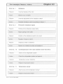
Chapter 2
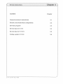
Content
Chapter
Acceeration and deceeraton curves
21
Lowest temperature for the Z 513 K
22
mb&ance switch off dates
23
7513K Sep 96bd
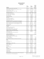
Chapter 2.1
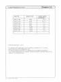
Acëleraon and deceleration times
Z 513 ; 230 V
Rotor
Acceleration
time in sec.
Deceleration
brake intensity
Deceleration
brake intensity
1?9TT
220.70 V05
60
254 sec.
81 sec.
220.70 V06
99
731 sec.
180 sec.
220.70 V07
59
294 sec.
134 sec.
220.80 V02
51
772 sec.
169 sec.
220.76 V03
51
753 sec.
169 sec.
220.78 V03
58
739 sec.
237 sec.
220.41 V03
17
91 sec.
17 sec.
Z513/Z513 K Sep. 96/bd
r22
Rotor No,
speed in rpm
Lowest sampe
8 C
22070 V06
5000
22070 V05
3600
22029 V03
3200
220.41 V03
2000
-5 C
22078 V02
15000
+5°C
220.80 V02
15000
+
220.76 V02
15000
+0°C
+
+10 C
-
5° C
2°C
Ambient temperature: +25° C
The absolute end temperatures can be subject to flucations of ± 2 C due to
power tolerances of the refrigeration unit.
The lowest sample temperature are depending on the ambient temperature.
If the ambient temperature is increasing, the lowest sample temperature that can be
reached, is increasing as well.
7513 Z513K Sep. 96bd
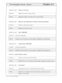
Chapter 23
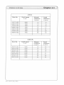
Imbalance cut off datas
Z 513
Rotor No.
Cutoff speed
in rpm
Aflowed
imbalance
Cutoff
imbalance
n grams
in grams
220.70 V06
2000
13
15
220.70 V05
1960
15
16
220.29 V03
1960
14
16
220.41 V03
1930
15
17
220.78 V02
1900
49
51
220.80 V02
220.76 V02
1960
52
54
1980
58
60
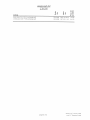
Z513K
Rotor No.
Cutoff speed
in rpm
Allowed
imbalance
in grams
Cutoff
imbalance
in grams
220.70 V06
1920
13
15
220,70 V05
1950
16
220.29 V03
220.41 V03
1960
1930
220.78 V02
1920
14
14
15
35
37
220.80 V02
1900
38
40
220.76 V02
1920
42
44
Z 513 Z513 K Sep. ‘96,bd
16
17
serwee Instrncnons
Chapter 3
Content
Chapter
General technical InstructIons
3.1
Electric and electronical components
3.2
Self test program
3.3
ServIce tips for Z 513
3.4
Service tips for Z 513 K
3.5
Coiling system Z 513 K
3.6
7543 Z513K
Sep ‘9Pbd
hapter3
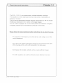
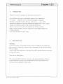
The Z 513 / Z 513 K is a microprocessor controlled laboratory centrifuge.
The actuation is a threephase asynchronous motor which is controlled by a
frequency converter.
The unit has an independent diagnostic program which helps you with the trouble
shooting by indicating the error number on the digital display.
The 12K / KBR is equipped with several safety facilities as imbalance recognition,
overspeed protection and overtemperature protection of the motor.
Pease foflow the be’ow mentioned safety nstructons for any kind of service:
The capacitor of the frequency converter can be under voltage, even if the
unit is switched off.
-
-
-
Don’t leave units without supervision, where you have removed some parts
of the housng and the unit is still connected to the main power.
Don’t bypass the lid safety contacts and never work with the lid open.
The VDE regulatons are valid for all electrical work that has to be done.
Z513 Z513K Sep 96bd
Z513
Electric and electronici components
Chapter 32
Content
Chapter
1.
Power board
32/1
2.
Contro board / Operationa contro
32l1
21
Adjustment of the operationa contro’
32I1
3.
Frequency converter
12/2
4.
Rotor identification and overspeed protection
32I2
5.
Speed signa
12/2
6.
Lid ock
12/2
7.
Imbaance recognition
3,2/2
Z513K Sep96bd
Electric and electronical components
Chapter 3211
1. Power board:
The power board is serving the low voltage supply of the centrifuge control system.
All fine wire fuses for the different distribution voltages are placed on the power
board (see chapter 4, layout of the HE 121.00.03).
The power board is electrically isolated and has an electrical strength of 4 KV.
It is also the central switching point for all inputs and outputs.
The signal line of the microprocessor controller is consisting of a flat belt cable, All
plug connections are placed in such a way that they cannot be accidentally
misconnected.
2. Front panel (Operational control):
On the front panel the CPU and the EPROM for the centirfuge software is located. The
front panel controls the hole centrifuge. If there is a defect please exchange the
complete panel, not only the prinited crcut board.
The signal line, the power supply lines and the temperature signal line are leaded to
the control board (no confusion possible).
The safety facilities are additionally safeguarded by a hardware circuit on the
power board.
If a mistake should occur you can see the error message on the digital display of
the front panel.
2.1 Adjustment of the front panel
The front panel can be used in different units, therefore it must be programmed
to the modeI where it is used. See chapter 3.3/6 in the self test program.
Attention: If you have to replace the front panel you have to make
sure that the panel is programmed correctly.
3 7513 KSp96bd
1
Z5
E1etri and electronleal components
Chapter 32I2
3. Frequency converter:
The frequency converter generates the drive signals for the asynchronous motor.
The converter leads the current, which is generated by the motor during deceleration,
to a heating resistor to reduce the current.
The frequency converter is connected with the power board by a senal interface.
On the converter is a green LED which lights when the frequency converter is working
correctly. A defect of the converter will be indicated as an error no. on the digital speed
display (see chapter 5 “Error messages”), and the green LED will not light.
4. Rotor identification and overspeed protection:
The centrifuge always recognizes the inserted rotor by a Hall-effect sensor.
All rotors are equipped with a coded indicator ring (magnet-ring).
The hall-effect sensor takes signals of the magnets and is passing them on to the
processor. If the preset speed is higher than the max. allowed speed of the inserted
rotor, the actual speed indication is flashing now during acceleration, beginning at
approx. 200 rpm.
But the CPU accelerates the rotor only up to the max. allowed speed of the rotor.
During acceleration the speed of the rotor will also be observed by a hardware circuit
which is integrated on the power board. Due to this double observation the motor can
never run with a higher speed than allowed.
5. Speed signaL
The actual speed will be measured by a Hall Sensor which is placed on the bottom
side of the motor
The signal will be transmitted by the power board to the control board and
the converter.
Z513
Z 513 K Sep. 95 bd
C
Electric and electronlcel comporwnts
Chapter 3.213
1)
6. Lid lock:
The Z 513 K series has a automatically lid lock. The lid lock doses the lid
automatically by using a motor force. A small amount of pressure is enough
to activate the locking system. It take approx. 6 sec. to dose the lid. By
pressing the lid key the lock opens within 6 seconds.
For emergency lid release. follow the Instruction manual “ Emergency lid release”.
7. Imbalance recognItion:
The Imbalance recognItion is effected by a micro switch which is controlling
the oscillating motion of the motor. The unit will stop If the oscillating motions
are too strong.
You have to follow the adjustment Instructions stated by the manufacturer.
Z513 Z51iK.’Sep. 96s’bd
Chapter 33
Self test program
Content
Chapter
1.
Activating of the self test program
13/1
2.
Keyboard test
13/1
3.
Indication test
13/2
4.
Input signal test
13/2
5.
Output signal test
13/5
6.
Indication of the software version
13/5
7.
Adjustment of the front panel
13/6
8.
Motor runin
13/6
9.
Elapsed time indicator
13/6
Z513 Z513K Sep 96bd
Chapter 3%3/1
$efl test program
‘
1.
Activating of the set test program
The self test program helps the service personnel to locate defects.
The program can be started as follows:
-
Open the centrifuge lid and switch off the main switch.
Press the keys “rpm/g-value” and time/radius” down together
-
and at the same time switch on the main switch.
Let go of keys “rpm/g-value” and “time/radius”,
Each digit of the display must now be a minus
2,
(-) symbol.
Keyboard test
With the keyboard test you can check the correct function of the foil keyboard.
Activate the self test program (as described under 1).
Press the key “rpm/g-value” to start the keyboard test. Then “1” appears on the
digital display brake.
By pressing the other keys always a number appears which is assigned to the keys.
rpm/g-value
quick
timeradius
up
lid
down
store
start
precool
stop
Number
1
2
3
4
5
6
7
8
9
Exit the keyboard test
If one of those numbers does not appear or if the keyboard test cant be started
or ended. you have to replace the complete operational control.
Z513/Z513K Sep. 96bd
C
Stifteetprofln
Chapter 33/2
-
3.
IndicatIon test
Activate the self test program (as described under poInt 1).
The indication test can be activated by pressing key “radius/time”.
The digits 0- 9 appear (half a second timing pulse) on all digital
indications. Also the LED’s of the keys, both minus (-) signs of the
temperature display and the point between the digits of the “radius” adjust
display are flashing (as well In half a second timing pulse).
With this test you can check If the displays are working properly.
Please watch carefully If all seven segments of each digital display are
working correctly.
Leave the indication test with “stop”.
4.
Input signal test
Attention:
During this self test It is possible that the motor is triggered uncontrolled by
the converter. That means, that the motor could start tuming without pressing
the “run’ button.
Please make sure that there Is nothing In the rotor chamber during the self test,
except of the rotor.
Take care of your fingers I
The Input signal test Is used to check the Input signals imbalance, lid lock.
motor temperature, speed, rotor identification and the input signal of the
Interface of the centrifuge control board.
ZC13 Z51KSep.96bd
I
Chapter 3I3
Self test program
Activate the self test program as described under point 1.
Press the key “lid” to activate the input signal test.
Then the letter “F” (standing for input) appears on the digital display for
brake. The nputs will be indicated on the digital displays for rpm/g-value’
and time/radius.
if there is a 1” on the indication (fixed or flashing) it means that there is a signal
or that the contact is closed
If there is a 0 it means that there is no signal.
rpm/g value
time mm
[1 I—
uu
f)
g)
a)
Imbalance
e)
Rotor identification (low speed)
b)
Lid lock
f)
Rotor identification (high speed)
c)
not occupied
g)
Serial interface
d)
Speed identification
a)
mbaIance
The display a has to be 0. If you press the imbalance switch (see
chapter 3.4/9) the display changes to 1.
b)
Ld ock
With the centrifuge lid open the display b is “0. If you close the lid the
indication has to show ‘1.
Z513
Z513K Sep 9Pbd
sentastprogram
C)
Not occupied
d)
Speed Identification
Chapter 33/4
As long as the motor is out of action the indication “d” shows “0”.
If the motor Is turning the Indication changes to “1”
Turn the motor by hand to check the sensor.
e,f)
Rotor Identification
The rotor identification sensor consists of two hall-effect sensors.
Due to that the indicator rings have two different dIameters of code rings,
but for each rotor only one of the rings are occupied (either Inner
or outer ring).
Depending on the rotor (high or low speed) the Indication “e” or “f” shows
a “1 ‘when the rotor Is turning.
Instead of using a rotor you can rub gently with a permanent magnet over the
sensor. After doing that, the Indication “e” and “F’ also have to show “1”.
g)
Seilal interface
For the Interface test the lid must be closed.
The display “g” has to show ‘1’.
This means that regarding the data flow between the operational control, the
power board and the converter are o.k..
If the display shows ‘0”:
Defect at one of the above mentioned electronicai components.
Defect at a flat Deft cable respectively directly at one of the interfaces.
-
-
Leave the Input test with “stop”.
Z513 Z513 K/Sep 96bd
Chapter a315
Self test program
5.
Output test
Activate the self test program (as described under point 1).
Press key quick’ to start the output test. Then A” appears on the
display ‘brake”.
With this test you can check the function of certain outputs by pressing
different keys.
Key
Function
quick
Starts the output test. The relay of the solenoid valve will be
closed at the same time solenoid valve open.
-
rpm/g-value
time/radius
The frequency converter relay is switching. The green LED of the
converter is lighting (for this function the centrifuge lid have to be
closed).
Not occupied for these models.
lid
Opens the centrifuge lid lock.
start
The compressor relay s switching. Compressor s working.
stop
This allows you to exit the output test.
6.
ndication of software version
Activate the self test program (as described under point 1).
Press the key “start”. You can see the software version on the digital
display “brake”.
Z513
Z13KS€p, 96bd
hapter33/6
7,
Adjustment of the operationa contro
Activate the self test program (as described under point 1).
The operational control has to be adjusted according to the centrifuge type where
it is going to be used. Press key store On speed/rcf indication appears the
centrifuge type for whch the operational control is adjusted for. For this unit “513’
has to appear. You can select centrifuge types by pressing keys “up” and “down”.
Press key stop” to store your adjustment Now the operational control shows the
adjusted voltage (115 V or 220 V). You can select the voltage as well by pressing
keys “up” and “down”. Press key “stop” to store your adjustment. At the same time
you leave the function “Adjustment of the operational control”.
8.
Motor runin
By pressing the “Run” button for about 5 seconds you can invoke the program
module “Motor run-in”
For a periode of 1 minute, the motor gets accelerated to 10% of the max. speed
of the insert rotor. After each further mnute the speed gets accelerated by 10 %
until the max. speed s reached. In the time display the run-in time is indicated
in minutes from 0 9.
-
Attention:
The runin is neccessary when the motor is repaced with a new one. The
runin is used to spread the grease in the bearing aB around the baN
bearings. A starting of the centrifuge to max. speed without the motor
runin can cause bearing damages at the new motor.
9.
E’apsed time indicator
Activate the self test program (as described under point 1).
Press the key “up’. The attended time of the unt will be indicated on the actual
dmplay. The attended hours appear on indication “speed/rcf’ and the minutes on
indication ‘time/radius”.
2513/7513K Sep 96bd
C
Sendcelipsforzsl3
Chapter 3.4
Content
Chapter
1. ExchangIng of the operational control
3.4/1
2. Dismounting of the centrifuge housing
3.4/24
3. Exchanging of the rotor Identification sensor
3.4/4
4. Exchanging of the motor
3.4/5
5. Exchanging of the power board
3.4/6
6. Exchanging of the frequency converter
3.4/7
7. Adjustment of the imbaiance switch
3.4/9
After doing any kind of assembling work, please make sure that all the
protection grounded contacts are connected correctiy.
Z513 Z513K ‘Sep.’96bd
D
I
Chapter 3A/1
SGrvice tips for Z 513
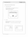
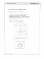
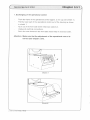
1, Exchanging of the operational control
—
-
Push the frame of the operational control approx. 2 mm up (see sketch 1).
Pull the lower part of the operatfonal control out of the housing as shown
in sketch 1.
Tip it out of the front side sheet metal (see sketch 2).
Unplug all electrical connections.
Set in the new element n the front side sheet metal in reversed order.
Attention: Make sure that the adjustment of the operational control is
correct (see chapter 3.316).
Sketch 1
7513’Z513K/Sep 96bd
Chapter 34I2
Service tips for Z 513
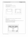
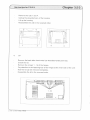
2, Dismounting of the centrifuge housing
a)
Back side sheet metal
Remove the screws 1 8 on the back side of the unit.
Take off the back side sheet metal.
Unplug the ground connection.
-
-
8
7
6
1
2
3
b)
4
Housing
Remove the operational control (point 1) and the back side sheet
metal (point 2a).
Remove screws 1 10 around the lower edge of the centrifuge.
-
-
-
\
\u
/
.q)
i__i
-
1
3
Z53
Z513K Sep. 96od
/
4
6
1
-
10
-
p
Chapter 34/3
Service tips for 2 513
-
-
Remove the nuts 1 and 4.
Unplug the grounded wire of the housing.
Lift up the housing.
Reassemble the unit in the reversed order.
-1
L
C)
-
-
-
-
-
-
--
U
3
4
j
Lid
Remove the back side sheet metal (as described under point 2a).
Unlock the lid.
Remove the screws 1
-
16 of the hinges.
Pay attention to the fastening bar of the hinges at the inner side of the unit.
Now the lid can be removed completely.
Reasemble the lid in the reversed order.
J
Z 513
Z 513 K Sep. 96:bd
Chapter
Service tips for Z513
3. Exchanging of the rotor identification sensor
Remove the operational control (point 1).
Remove the centrifuge housing (point 2a b).
Take off the motor protection cover (screws a to c).
Unplug the sensor cable at the power board.
-
Release the flat head screws 1 3 of the sensor flange.
Take the flange together with the sensor out of the unit.
Take care of the sensor cable
Exchange the sensor with a new one.
Reassemble the unit in reversed order.
Z513
Z513KSep. 96bd
,
Srvice
Chapter 3 4/5
tips for Z51 3
4. Exchanging of the motor
-
-
-
-
Remove the operational control (as described under point 1)
Remove the centrifuge housing (as described under point 2).
Remove the rotor sensor (as described under point 3).
Unplug the connection cables of the motor, you will find the location of the
connectors n chapter 4.
Remove screws 1 4 of the motor mount.
Bind a pice of stnng to the conectors of the motor wires, this allows you to pull
the wires of the new motor back through the holes in safty frame.
Lift the motor out of the unit.
Pay attention to the arrangement of the wiring when replacing the motor.
Reassemble the unit in reversed order.
1
3
2
4
I
Z 513 Z 513 K Sep 96 bd
R
Chapter
Service tips for Z 513
5. Exchanging of the power board
-
-
-
Z53
Remove the operational control (point 1).
Remove the centrifuge housing (point 2 a-b).
Unplug all cable connections of the power board.
Remove the screws 1 7.
Reassemble the unit in reversed order.
Z53 K Sep. 9bd
-
(rvietipsforZ513Ghapter34f7
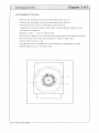
6. Exchanging of the frequency converter
-
-
Unplug all cable connections of the frequency converter.
-
-
-
Remove the operational control (point 1).
Remove the centrifuge housing (point 2 a-b),
Remove the screws 1 4 of the frequency converter and take it out of the unit.
Attention, before you place the new frequency converter, you have to apply
heat conduction paste on the seating.
-
Reassemble the unit in reversed order.
2
I
Z513
Z513K!Sep, 6bd
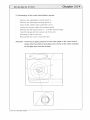
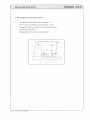
9. Adjustment of the imba’ance switch
-
-
-
-
-
-
Insert a rotor m the centrifuge.
Load one bore hole of the rotor with an imbalance switch off weight
mentioned in the chart (see chapter 3319). If a microlitre rotor is placed
in the centrifuge you have to insert several adjacent reaction tubes.
Start the centrifuge
the unit should switch off at the cut off speed mentioned
in the chart (chapter 3.3/9) for the corresponding rotor.
If the unit is not switching off you have to release the fixing nut (1).
With the adjustment screw (2) you can adjust the imbalance switch off
more sensitive (turn right).
You can reach the screws from the left side at the bottom of the unit.
If the unit is switching off, load the rotor with the allowed imbalance weight
(see chapter 3.3/9).
Start the centrifuge the unit should not switch off again. If required. adjust
the imbalance switch off with the adjustment screw (2) less sensitive.
If you have to readjust the imbalance switch for the test with the allowed
imbalance. you have to repeat the procedure with the imbalance switch
off weight.
-
-
/
-
0
2
Z513
Z512KSp.96bd
---
Chapter 34I9
Service tips for Z 513
Z 513
Rotor No.
Cutoff speed
in rpm
Allowed
imbalance
in grams
Cutoff
imbalance
in grams
220.70 V06
2000
13
15
220.70 V05
1960
15
16
220.29 V03
1960
14
16
22041 V03
1930
15
17
220.78 V02
1900
49
51
220.80 V02
1960
52
54
220.76 V02
1980
58
60
Z 513 / Z 513 K iSep. 96 bd
Content
Chapter
1. Exchanging of the operational control
3.4/1
2. Dismounting of the centrifuge housing
3.4/24
3. Exchanging of the rotor identification sensor
3.4/4
4. ExchangIng of the motor
3.4/5
5. Exchanging of the power board
3.4/6
6. Exchanging of the frequency converter
3.4/7
7. Adjustment of the imbalance swItch
3.4/9
After doing any kind of assembling work, piease make sure that an the
protection grounded contacts are connected correctiy.
Service tips br Z 513 K
Chapter 35/1
1. Exchanging of the operatona contro
-
-
Push the frame of the operational control approx. 2 mm up (see sketch 1).
Pull the lower part of the operational control out of the housing as shown
in sketch 1.
Tip it out of the front side sheet metal (see sketch 2).
Unplug all electrical connections.
-
Set in the new element in the front side sheet metal in reversed order.
Attention: Make sure that the adjustment of the operational control is
correct (see chapter 33I6).
Z513
Z513KSep96bd
Chapter 3.5/2
Service tips for Z 513 K
2. Dismounting of the centrifuge housing
a)
Back side sheet metal
Remove the screws 1 1 0 on the back side of the unit.
Take off the back side sheet metal.
Unplug the ground connection.
-
-
10—
-6
1
3
b)
-
4
Housing
Remove the operational control (point 1) and the back side sheet
metal (point 2a).
Remove screws 1 10 around the lower edge of the centrifuge.
/
-
3
Z513/Z513KSep 9bbd
c
vicetpsforz5i3KChapter35I3
Remove the nuts 1 and 4.
Unplug the grounded wire of the housing.
Lift up the housing.
Reassemble the unit in the reversed order.
r
7uu
-i
L..
c)
Lid
Remove the back side sheet metal (as described under point 2a).
Unlock the lid.
Remove the screws 1 16 of the hinges.
Pay attention to the fastening bar of the hinges at the inner side of the unit:
Now the lid can be removed completely.
Reasemble the lid in the reversed order.
-
Z 513 / Z 513 K Sep. 96.bd
r
Chapter 3.5/4
Servie tips for Z 513 K
3. Exchanging of the rotor identification sensor
-
-
-
Remove the operational control (point 1).
Remove the centrifuge housing (point 2).
Take off the rubber motor protection cover.
Unplug the sensor cable at the power board.
Release the flat head screws (1 3) of the sensor flange.
Take the flange with the sensor out of the unit.
-
-
-
-
Exchange it with a new one.
Reassemble the unit in reversed order.
Attention: Continue to apply pressure to the outer edge of the cover until it
snaps into the position and grips onto the lip of the steel chamber.
An airtight seal must be formed,
Z513
Z513KSep. ‘96bd
Chapter 35I5’
Service tips for Z 513 K
4. Exchanging of the motor
-
-
-
Remove the operational control (as described under point 1)
Remove the centrifuge housing (as described under point 2 a).
Remove the rotor sensor (as described under point 3).
Unplug the connection cables of the motor, you will find the location of the
connectors in chapter 4.
Remove screws 1 4 of the motor mount.
Bind a pice of string to the conectors of the motor wires, this allows you to pull
the wires of the new motor back through the holes in safty frame.
Lift the motor out of the unit.
Pay attention to the arrangement of the wiring when replacing the motor.
Reassemble the unit in reversed order.
-
-
-
-
1
3
-
Z 513
Z 513 K’Sep. 96,bd
4
vietipstqrZ5i3KChapter35/6
5. Exchanging of the power board
-
-
-
Remove the operational control (point 1).
Remove the centrifuge housing (point 2 a-b).
Unplug all cable connections of the power board.
Remove the screws 1 7.
Reassemble the unit in reversed order,
-
-I
Zfl3
Z513K’Sep. 96bd
C
Chapter
Service tips far Z 513 K
6. Exchanging of the frequency converter
-
-
Remove the operational control
Remove the centrifuge housing
Unplug all cable connections of
Remove the screws 1 4 of the
(point 1).
(point 2 a-b).
the frequency converter.
frequency converter and take it out of the unit.
Attention. before you place the new frequency converter, you have to apply
heat conduction paste on the seating.
Reassemble the unit in reversed order.
-
—
-
2
Z 513
/
Z 513 K!S9p 96 bd
r
Chapter 3.5/8
Bervlcadpeforzslak
-
9. AdJustment of the Imbalance switch
-
-
-
-
-
-
Insert a rotor In the centnfuge.
Load one bore hole of the rotor with an Imbalance switch off weight
mentioned In the chart (see chapter 3.4/9). If a microlitre rotor Is placed
In the centrifuge you have to Insert several adjacent reaction tubes.
Start the centrifuge the unit should switch off at the cut off speed mentioned
In the chart (chapter 3.4/9) for the corresponding rotor.
It the unit is not switching off you have to release the fixing nut (1).
With the adjustment screw (2) you can adjust the Imbalance switch off
more sensitive (turn right).
You can reach the screws from the left side at the bottom of the unit
If the unit Is switching off, load the rotor with the allowed Imbalance weight
(see chapter 3.4/9).
Start the centrifuge the unit should not switch off again. if required, adjust
the Imbalance switch off with the adjustment screw (2) less sensitive.
If you have to readjust the Imbalance switch for the test with the allowed
imbalance, you have to repeat the procedure with the Imbalance switch
off weight
-
-
-
0
Z513 Z5ISKSep 96bd
a
Chapter 3%5/9
Service tips for Z 513 K
Z513K
Rotor No.
Cutoff speed
in rpm
Cutoff
imbalance
in grams
in grams
22070 VOG
1920
13
220.70 V05
1950
14
15
16
220.29 V03
1960
14
16
220.41 V03
220.78 V02
1930
15
17
1920
35
37
220.80 V02
1900
38
40
220.76 V02
1920
42
44
\
Z513
Allowed
imbalance
Z513KJSep. 96bd
Refrigeration system Z 513 K
Chapter 36
Content
Z 513
Chapter
1.
Functional description of the refrigeration system
3.6/1
2.
Keyplan of the refrigeration system
3.6/2
3.
Emptying and filling with Freon
3.6/3
4.
Lowest temperatures (depending on the rotor)
3.6/5
Z 513 K Sep. 96bd
C
Refrigeration system Z 513 K
1.
Chapter 36hz
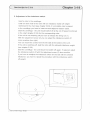
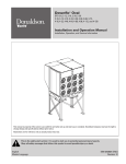
Functional description of the refrigeration system
The quantity of the coolant passed Into the evaporator Is controlled by a solenoid vaive
and an expansIon valve. A detectIng element continuously measures the
temperature at the evaporator output. This detecting element regulates the injection
nozzle, because of this the evaporator gets always the neccessary quantity of coolant.
So you can reach the maximum capability of the refrigeration system at any
operating status.
As soon as the required preset temperature is reached, the soienold valve
interrups the cooiant drcult. The solenoid valve reopens the circuit as soon as
the temperature rises and passes on coolant to the evaporator again.
The response time of the soienold valve is controlled by the CPU.
From the temperature sensor. placed in the rotor chamber, the processor receives the
information of the chamber temperature.
As the actual temperature of the samples is not necessarily the same as the chamber
temperature, the microprocessor caicuiates the sample temperature for the respective
rotor.
This value will be indicated on the digital temperature display. The temperature
control of the microprocessor works according to the calculated value.
Therefore the user can seiect the required sample temperature (± it C). Samples
cannot be damaged by discrepancies between chamber temperature and sample
temperature.
Z 513.
Z 513 K.Sep. ‘96 bd
}
0
(0
(0
cc
CD
-p
C-fl
C-fl
-
-
“Schccder valve
Evaporator
Compressor
Expansion valve
Solenoid valve
Drier/Collector
Condenser
U)
CD
Cl)
0
CD
CD
cr2
-
CD
CD
0
CD
CD
C,
1\)
V
(D
0
w
-
CD
0
—
C
Refrigeration system I2KBR
3.
Chapter 3.6/3]
EmptyIng and filling with coolant (R134a)
For doing this work you have to have the following equipment:
Coolant suction Implement with collecting tank, vacuum pump, vacuum measuring
instrument, quantity measuring system for the freon and a manometer combination.
a)
-
-
-
-
-
-
b)
-
-
-
-
-
-
-
Emptying of the refrigeration system
Remove the housing parts until the refrigeration system Is self-contained
(see chapter 3.5).
Connect the front panel back to the system, so that the unit can work
without housing.
Connect the coolant suction implement with the valve (see sketch, chapter 3.6/4).
Start the self test program and choose test range 4 (output test) solenoid
valve open.
Evacuate the coolant from the system.
Now you can carry out the necessary repair work on the refrigeration system.
-
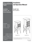
Filling of the refrigeration system
Connect the vacuum pump, the manometer combination and the coolant
bottle (R 134) to the valve (1). (see sketch. chapter 3.614).
Start the seif test program and choose test range 4 (output test) solenoid
valve open.
Evacuate the refrigeration system for approx. 30 mm..
Switch off the vacuum pump.
Make sure that the system remains in a state of vacuum.
if not the system is leaking.
Fill up the system with 800 grams coolant R134a.
Check all tube connections very closely with a leak indicator.
Attention: Only use R134a.
Riling quantity must never exceed 850 g.
Z513 Z513K’Sep’961bd
-
R
Chapter 6I4
Røfrigeration system I 2KBfi
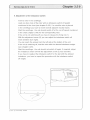
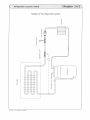
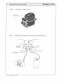
Sketch:
Compressor, FiWng vave 1
Fifing valve 1
(Schrader valve)
Sketch:
Manometer combinaflon, vacuum pump, cooant botfie
High pressure
Vacuum
rneasunng
mstru ment
High pressure
Sight glass
Not applicable
Connechon to
the compressor
Z 513’ Z 513 K Sep 96 bd
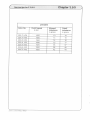
Chapter 36I5
Lowest temperatures Z 513 K
Rotor No.
speed in rpm
Lowest sample
22070 V06
5000
220.70 V05
3600
220.29 V03
3200
220.41 V03
2000
220.78 V02
15000
+5C
220.80 V02
15000
+
2°C
220.76 V02
15000
+
0 C
+
8° C
+10 C
-
-
5 C
5° C
Ambient temperature 23° C
The absolute end temperatures can be subject to fluctuations of ± 2° C of the cooling
compressor due to output variations.
The lowest sample temperatures depends on the ambient temperature.
If the ambient temperature increases, the lowest sample temperature that can be
reached, increases as well.
\_________
Z513
Z513 K/Sep
96:ba
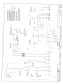
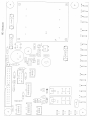
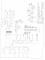
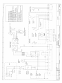
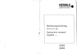
Wiring
diagrams Z 513
Chapter 4
/ Z 513 K
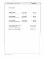
Contents
Wiring Diagram
Z 513, 120 V
LS 0173
Plan of electric installation
Z 513, 120 V
LS 0174
Wiring Diagram
Z 513, 230 V
LS 0166
Plan of electric installation
Z 513, 230 V
LS 0167
Wiring Diagram
Z 513 K, 230 V
LS 0169
Plan of electric installation
Z 513 K, 230 V
LS 0170
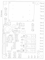
Circuit diagram, power board
HE 121.00.03
Layout, power board
HE 121.00.03
Layout, control board 26KM
271.01.02.02
Layout, control board 26KMR
271.01.12.02
Z513 7513K Aug95 bd
—
I
TRIO
LKO17
Kessel
hamber
LKO1S
Riickwand
back sheet metal
LKO16
GebSuse
housing
Surpreosor
Interterenco
Nelofilter
LK1SO
Dais switch
IS
Feinsicherung
lose
.F.
2 X 1SAT
.4-
Netzschalter
120V 50Hz
PEL—>-r-j
1
NI—)
hf
I 6
1K134
7
Choke
11
drossel
Funkentotdr
I
L
is
Ii-
L
tTh
I
power-unit
NT HEi3.QO.O3
1ol
(_
Oeckelkeniakt 2
-L
-
-
Dr eh strom- ynchronmo tar
asynchronous solar
—F
0eckIkeeta5t 1
:3
L
LkOll
Molorschloll
lid—lock—motor
frequency changer
Frequenz-Umrichter
LKOIS
Lt(O17
66018
LK127
i4-
-
Unwuchtochalter
I imbalance switch
Erdungoserbindung L190
Erdungsverbindung L280
Erdungsverbindung UCO
Flachbandkabel lOpol.l.25O NT-Umrichter
LK37 Rotortlansch koropletl H25
66150 ‘derbgSchalter-Fitter
LK15I. Flachbandkabel bOpol. NT-tIP-CR
LK1S7 Verbg.NT-Unwuchtschal[er L600 p3
1St, 16109 (odierstecker 120V
1St. LK134 Netzmodul I2OV1SAT
1St. LK 158 VerbyFil r-NJ-Umrichter-LOfter
ISt.LK186 Ersatasicherung 16AT 6,3x32
2St.
251.
1St.
151.
1St.
1St.
1St.
1St.
Dektkentekt 3
lid.witch
Schalter
2St. LKO1I Erdunqsverbindung COO
1St, LKO1S Erdungsverbindusg l.lkO
I1Sj
I
16
L
1
3
121
LLLJ0LHE_Lj_
J
13
J12
111
Hi
19
Lk108
I
NT HE 134.10.03
12j
—
3
9
L
1
HERMLE
Labrlechnk Srnbtt
speedsansor
-
E-
16137
Li., .____::i
1
i6
Somuan23ovSo/6oHJ
wirinp-diaqrans
-
HE 1Z.UOO3
H
RorSnø.
LI
LKO1I 9
Erdungsvrbndjn 1.90
LK01S Erdungsverbindung IlLS
LKOI6 Erdungsverbindung L190
LK017 Erdurigsverbndun 1280
LK018 Erdungsverbindung L140
LK127 FtachbHndkabet IOpot.L250 NT4.imrichter
LK13J Rolortlarisch komptt [i25
LK150 Verbo.Schalter-F9ter
LK1S4 Flachbandkabel LOpoI. NT-MP—LP
1K 157 VerbgNT-Unwucht schat ter L600 p3
r
1
1.615’.
Z
.
4
7
2
j
0
V
5
13
0
1
.
[S 0199
Mikrocotroiler HE 135.00.03
LI
1..
16015
1St, LK108 Coderstecker 230V
15L 1.6128 Net zrnodul 230V16A
1St. LK1S6 Verbg.F0ter-NT—lJmrkhtr-LSfter-5chijlz
lSt,1K185 Ersatzsictierung 16AT 5x20
2St,
1St.
2St.
2St.
1St,
1St.
1St.
1St.
1St.
1St.
____
r
-
i
116017
Nane
19
2
1k120
FunkentotOr
drossel
[ho Re
3
11
100
JTcma
rnfo
,
Erm,z lOr
-
_UJ LL
LonE
Rkckwancl
back sheet metal
16016
Kessel
chamber
Geh2us
housing
LKOI6
Netzlilter
Isterlererico
Surpressor
Hetzschalter
main switch
Feinsicherung
fuse
—F
2 X 16AT
PELr
230V S01tz
1
Z
2
L
5
16127
I
I
-
Dr eh St r om-s y nchr onmo I or
asynchronous motor
Id-otnlch
Onchelkoolakl
2
Oetklkoo[kl 1
lid-much
LZ
S
power-unit
NT HE131OD3
L6011
Motorschlofl
Iid-Iockmotor
Frequenz-Umrichter
Irequency changer
I.
6
I
-
LK57
Unwuchtschaller
imbalance switch
Erdungsoerbindung 601
Erdungsverbisdung 1001
Erdungsverbisdunq 190L
Erdungsverbindung 2801
Erdunysoerbindung 80L
Temperatursenoor
Codierstecker 230V
Fjathbandkabel lQpcl.1250 NT—lJmricht er
Netzmodul 230V16A
Rolorllansch komptell 1125
Verbg.Ksmpressor Druckschaller,Magnela.
Verbg.Schal1er—Filer
Flachbandkabel 40 psI. NT-MP-LP
VerbgFdter-NT-Umrichter-.Lufter-Schutz
VerbgHT-Un .ichtschalter 6001 3p.
8
EJZ t:z
[odichaller so
oitch on
Dnck.lRoolkl 3
lid— loutS
Schalter
251. 16011
1St. LKOIS
251. 16016
1SL 1601)
251. LKO18
151. 16107
151. 16108
1St. LK127
1St. LK12B
151. 16137
151, LK1O 6
151. 16150
151, LK1SI.
1St. 1K156
1St. LK157
7
1
1
2
Lk109
NT HE 13.i0.03
LZHP
3
I
L
J
:2i
spocdsensor
S
LKI3J
1 12OOO1
din gram
EIfl
Rn—S,nni-
6
I
r
L6154
LK01l
LK015
16016
16017
L6018
16127
LK13I
8
Erd gs rb-dur 180
Erdungsverbinctung L10
Erdunserbindung 1190
Erdung erbindung 1280
Erdungsverbkidurig L11O
Flachbandkabel lOpol.L250 NTUmrkhtr
Rotortlansib koniplot I 1-125
I
-
274-OOVO2Z5131+
Mikrocotro[ler HE 1350003
-
1St, LKISO Vorbg.Schatter-Fittnr
151, 16156 FachbandkabnI kOpoI. NT—MPLP
St. LK1S7 Verbg,NTUnwuhtschalter L600 p3
1St, 16109 [odiersteckr 120Y
1St. 16136 Netzmdut 12OV1SAT
1St. 16158 Vnrbg,Filter-NT-Umrichter-LOltor
1St.LK186 Ersatzskhnrung 16AT 6,3x32
251,
1St.
251.
2S1.
151,
1St,
1St.
7
NT HE 13.1O.O3
HC 12OOOJ
J
3
j
LK1J1
H
RoSt
.L
LKO15
J zrz Jfd
MikrocotroHep HE 135.00.03
LK1SI.
251. LKO11 Lrdungsvorbindung 80L
ISI. LKO1S Erdungsvrbindunq 1tO1.
251. LKO16 Erdungsvrbindurnj 190L
SI. LKO12 Erdunsverbinduq 2801
251. LKO18 [rdungsverbindung 80L
SI, LK1O7 Trnpratursnsor
151, LKIO8 CodrsIecker 230V
151. LK1Z7 Flchbandkab& lOpo[L250 HT-Urnrichler
151. LK12B Helznwdul 230V15A
SI. LK137 Rotorllansch komplell H25
SI. LK1kO VerbqKornpressor Druckschaller,Haqnelv.
51, LI150 Verbg.Sc1I1er-FiIer
ISI. LK1S4 FlachbanJkobel L0 pot. NT-MP-LP
ISI, 1K156 ‘rbjrtIor.NTlJrnrichIerLuIterSchuFz
151, LK1S? Verhg.NT-Unwuchlothalter 600L Op.
EOOOt7 H
ØØØt1.I{ autr1c1H
l’0
zalJ
!4rfl 0I3330
(5-i)—-
(FilZlJ
(tt1it1\
U1UiLi(f
E3c/
Joqo]
—
-----“
—-
—
L
!
0
)—
Jlj
ase ) S JOUII.11(S01)
—
—
1__
Hq°(J 1(1
S
-—-
I
j
10(1
bud-i
(51030501,1
-/
11l
j
1)—
-
—
—
13
13
—
:::cLo
—
‘
——
—
—
—
1i1Ti—
111
‘01
—-iacL
—
0011
1
(
!
!i!}——E1
!
]t---—Eu)-—
1
0
(ii
3
colon
[
—
—
-
/
.-—-——
C
/-c
-
3
‘UI
0
•lt
II
110
—1
ill
Ut
‘Ilfl
0
0
0
2 zzzz
o
0
CD
Li
CA
r
SL
CA
CA
Lii
EEz
:
CA
oj
0
CA
Li
9
L
.0
P
©
©
CA
Li
0
C
li
9
N
(N
—
CO
Li
2ZZE
CD
—
PP
1-0
112
U:
tz: D:
rr:E:3
I
1iiu
au1d1a1zaN
oO[t7EI 3H
iOiA
qw9
i
b9G/
aSSQJISJOESNNqSQO
EJOULq
qç
W3H
18111
LJ
Cd
LG111C
NlIt.fl
Old
9) 0
10
00
£
90
110
—
IlIII
€1
9)
‘9
‘—
—\
_——ct1
tpNq.
9)
19)
9)
(9)
‘9--------—----—CI0J
9)
11
9)
9)
9)
9)
9)
9)
9)
9)
l•I’ll Ion OILE
9)
—-—-<)
9)
L
EN
IN
101)1
—
—
—
IR 19
Kessel
chamber
I KO 17
R0ckand
back sheet metal
16016
G3use
housing
LKOI6
flefzfiifer
Inferference
Surpresusr
main switch
Nefzschafter
IS
Feinsicherung
fuse
F
2 6 bAT
PEr1
230V 50Hz
1
2
lb
16128
Ii
-ill
I
j
19
Lk121
I
5
H
LKO17
Orehufrem-Iuynchronmofor
asynchronous inofor
tkl-ooilch
Elesketkeolakl
2
DeskeIkooll 1
lid-s oilch
NT HE’14..OO.O
EZZ
pow2runi
6
1.6011 Erdungverbindung 1.80
LKO1S Erdunguverbisdung L160
LKO16 Erdungsverbindung 1190
LKO17 Erdungsverbiodung 1280
t..6018 Erctungsverbindung 1110
L6121 Flachbandkabel l0pot.L 250 NT-Umrichter
16137 Roforftansch kompteft H25
LK1SO Verbg.Schatler—Fitfer
LK1S4 Flachbandkabel kOpot. NT-MP-IP
10157 Verbg.NTtJnwuchtschutfer 1600 p3
I
-
L
4
_
j
r
-
z
10
L:
Lt(1S1
Kj
1St. L0108 Codierutecker 230V
1St, 16128 Netumodul 23OVtbA
1Sf, LK1S6 0
Verbg.Fitfer-NT-Umrichfer-LOffer-Schijf
1St.LK18S Eruatzsicheruoq 16AT So20
2Sf.
1St.
2Sf.
2Sf.
1Sf.
1St,
1St.
1Sf.
1St.
1Sf.
Eodsrhaller rj
swich on
TemperafurabhOogiger Schalter
biroef attic cutoff
LL
IkOti
tid-lock—mofor
Moforochiol)
Frequeno -Umrichl or
frequency changer
ZZZ° L
i
3
5
Funkenf S fdr
drosset
Choke
I
3
0
0
0)
co
0
0
N
0
0
(0
-J
(3
0
0
0
SL
0
N
U-)
0
-_
0
-,
Lr:Ez1
00(00
LJ
+
h0
U
—
P
c
E71
S.
c
Li
c
Hi
EEE
J::LJ
-i
z
(3
c-
ci
:HJ
P
‘°-i
L
jLJ
0
HH
I7
cj
0
N
(0
RH
L
c-
::
1 U
L
°
12
IR
(3
tn
C3
Error messages: Beasons / Actions
Chapter_D
PREFACE
These error messages can help the service personnel to locate defects
faster is they occur.
The diagnoses listed in this chapter are not necessarily accurate. They are theoretical
defects that can occur and appropriate solutions. Please always make your own
diagnosis with the help to the self test program
Please always inform us about any type of defect you find and which is not mentioned
in this chapter.
Only with your help we are able to improve and complete our service manual.
Thanks in advance for your help.
Hermle Labortechnik GmbH
Z 513 7 513 K /Sep 96’bd
Error messages: Reasons / Actions
1.
Chapter 511
Description of the error message system
The error message wilt be indicated by a certain number on the digital speed
display. At the same time “ERROR” appears on the preset display.
Error Nr. 1
-
49 (Forced stop)
if one of the above errors occurs, the rotor wilt be braked from the preset speed to 0.
As soon as the rotor has stopped, the error message can be reset by opening and
closing the centnfuge lid.
Error Nr. 50
99 (Emergency stop)
If this occurs. the frequency converter will be switched off and the rotor will be
coast to a stop. The error message can only be reset by switching the main switch
off and on.
If the unit stops due to an error indication you should restart the unit to check if the
error occurs again.
The error numbers which are not listed in this chapter are not in use at the time of
publication and they are reserved for future use in broadening the error recognition
prog ram.
Z513
Z513K Sep 96bd
D
F
Chapter 5/2
Error rnss: Rspis I Actions
Error no: 1
r
Imbalance
son:
Incorrect loading of the rotor
Action:
Balance your samples
L
Reason:
-
Incorrect adjustment of the imbalance switch
b
Actiøn:
Readjust imbalance switch according to chapter 3
Error noW: 2
Permanent imbalance signal
Reason:
Parting at the imbalance signal cable
parting_of
—
—
Reason:
——
—
Position of the imbalance switch not correct
Action:
F
the cable
imbalance switch
Reason:
Imbalance switch is defective
Action:
Replace the imbalanda switCh and readjuCt it
Error noW: 1 0
Overtemperature in the rotor chamber (more than 50°C)
Reason:
Failure of the refrigeration system
ActiQn:
Check the refrigeration system and repair it
Reason:
Temperature sensor defective
Action:
—
Replace temperature sensor
--
Error no: 11
Temperature sensor
Reason:
Short circuit at the temperature sensor
Action:
Replace temperature sensor
-
—I
7513
7513K/Sep96/bd
Error messages: Reasons / Actions
r
Chapter 5/3
Error no.: 20
No rotor identification
Reason:
No rotor inserted
Action:
Insert rotor into the unit
Reason:
Rotor identification sensor defective
Action:
Reglace identification sensor
Reason:
Inserted rotor has no indicator ring
Action:
Usea correct rotor
Reason:
Rotor is not seated on the motor shaft correctly
Action:
Reseat the rotor on the motor shaft
Error no.: 21
Start bit is missing
Reason:
A magnet of the indicator ring is missing
Action;
Exchange the inccator ring of the rotor
Error no.: 22
Rotor is not mentioned in the rotor chart
Reason:
Rotor is not authorized for this unit
Action:
Insert only rotors authorized for this unit
Error no.: 25
Power failure
Reason:
Power failure while rotor is in motion
Action:
Open and reclose the lid, restad the centrifuge
S
Z 513 Z 513 K ‘Sep 96’bd
—
—____
—
-________
C
Error messages: easons / Ations
Error no: 30
Radius correction
Reason:
Radius correction value too big
Chapter 514
Adjust the radius correction to the correct value
ctiop:
Error noW: 36
Relay for the frequency converter cannot be released
Reason:
Defect on the power board
tion:
Replace the power bOard
Error no: 40
Error EEROPM
Reason:
Serveral posibiities
Action:
Restart unit, if the failure occures again, replace the contrQl panel.
Error no: 41
Power failure EEPROM
Reason:
Serveral posibilities
Action
Restart unit, it the faure occures again, replace the control paneL
Error no: 50,51 Memory failure
Reason:
Internal or external memory failure
Action:
Restart the unit, if the faure occurs again, replace the control panel
Error no: 55
Overspeed
Reason:
Overspeed sensor or motor speed sensor defect
-
Action:
Check the overspeed sensor or the motor speed sensor and
replace if necessary
I
5513
Z5l3KiSepS6/bd
F
Error rnessage: Reas I Actions
Reason:
Chapter 5/5
Control panel or power board defect
d
[
Error no: 60
Motor speed sensor signal is missing
Reason:
Motor speed sensor defective or parting of a cable at the sensor
Error no: 61
Speed signal without a turning of the rotor
Reason:
Speed sensor is broken
Error no: 70
Interface of the frequency converter
Reason
Communication of controller, power board interface cable and
frequency converter is not working
Action:
Interface test
Localization of the defective part by changing thø components
Reason:
Unpluged interface wire
Action:
Plug in the interface wire plugs correctly
Error no: 82/83 Cutoff power board
Reason:
on:
7513
7513K Sep SSibd
frequency converter
Overcurrent, overvoltage or undervoltage due to power
supply fluctuations
Restart the unit, take care that the power supply is stable
Chapter 5/6
Error messages: Reasons / Actions
Error no: 84
Motor temperature / Frequency converter temperature
Reason:
Defect at the motor (winding damage, bearing damage)
Reason:
Overtemperature switch in the motor is defective
J
Reason:
Defect at the frequency converter
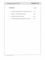
Reason:
Fan of the housing ventilation is defective, vent hole is covered,
ambient temperature is too high
.
J
r
Error no: 90
Lid was open during run
Reason:
Lid lock switch is defective
Action.
Replace the lid lock
Reason:
Wire to the lid lock is broken
Error no: 94
Votage drop during operation
—
Reason:
Voltage drop of more than 10 Volt
i
Lon:
Z513/Z513 K Sep 96/bd
Restart
The uit
rQ
0
LU
Art ice
frequency converter, 230 V with 2 PCB
913.019
20-0238
power board for control panel with 1 PCB 120 V I 230 V
913.022
HE 134.10.03
151,00
control panel with 1 PCB
913.033
271.01.11.02
455,00
frequency converter, 230 V with 1 POE
913.034
20-0243
596,70
motor, 230 V / 120 V
923.007
274.08.40.02
393,80
housing (for hinge version)
933.031
277,01.13.00
340,70
lid complete (for hinge version)
933.032
277.01.21.01
269,30
fuse 16 AT, 230 V, 5 x 20 mm
940.025
25.0095
5,10
fuse holder 230 V
940.026
25.0096
16,40
808,90
cover for fuse holder
940.032
25.01 09
7,20
fan, 230 V
940.046
32.0033
54,10
micro switch imbalance”
940.069
38.0082
10,20
rocker switch power’ vertikal
940.086
38.0202
8,20
line filter, 230 V / 120 V
940.160
40-0111
87,80
31,70
temperature sensor for control panel with 2 POE (analog)
940.168
LK046
temperature sensor for control panel with 1 POE (digital)
lid lock, motor-driven, 230 V for control panel with 2 PCB
940.179
LK1O7
940.185
250.05 VOl
286,70
lid lock, motor-driven, 230 V for control panel with 1 POE
940.187
250.05 V07
278,50
imbalance switch
940.190
274.01.02.04
29,60
rotor sensor
940.191
LK137
133,70
38,80
contactor
940.192
30-0137
95,90
speed sensor (brown housing)
940.199
32-0220
63,30
fuse set, 230 V (16 AT)
940.213
LK185
5,10
power connection with fuse holder, 230 V
940.217
LK128
73,50
imbalance switch, only conecting cable
940.220
LK157
20,40
magnet for speed sensor (without housing)
940.236
44-0047
28,60
potientiometer 10 K
940.245
940.245
micro switches set for motor driven lid lock
940.260
29,60
87,10
motor for lid lock 230V
940.261
motor for lid lock 120V
940.262
speed sensor (white housing)
940.263
8,20
87,10
940.263
magnet for speed sensor (with housing)
940.264
940.264
stopper (imblance)
950,006
20.5054
5,10
centrifuge rubber feet
motor rubber mount, diam. 30 x 30 mm, 50-55” Shore
950.014
26.5034
950.019
26.5057
9,20
10,20
hinge
950.131
38-5597
22,50
lid latch
950.132
274.01 .06.04
22,50
motor rubber mount
950.136
274.01.26.04
21,50
motorcover
950.137
277.01.24.03
67,40
chamber gasket, 1630 mm, grey
950.152
950.152
64,30
injection nozzle
960.003
23.5141
31,70
117,30
solenoid valve, 230 V
960.029
41 .5137
sight glas
960.034
244.00.51.04
6,20
expansion valve
960.051
24-5077
80,60
dryer
960.052
39-5106
106,10
compressor
960.053
41-5178
499,80
condenser with fan
960.054
41-5179
198,90
pressure guard
960.055
23-5149
55,10
starting relay
960.066
960.066
75,50
starting capacitor
95,90
960.075
960.075
power board 230 V for control panel with 2 POB (exchange part)
R913.010
R266.08U10.02
195,90
control panel with 2 POE (exchange part)
R913.013
R271.01.12.02
481,50
page 1 of 2
effective Ol January, 2003
up to 31 Dezember, 2003
spare part list
Z513
cQ
0
cl)
Article
—
.Li.I
.9
frequency converter, 120 V with 2 P08
913.004
20-0235
power board for control panel with 1 PCB 120 V/230 V
913.018
HE 134.00.03
15100
frequency converter, 230 V with 2 P08
913.019
20-0238
80890
frequency converter, 120 V with 1 P08
913.021
20-0242
50900
frequency converter, 230 V with 1 PCB
913.034
20-0243
59670
40400
72020
control panel with 1 P08
913.035
271.01.01.02
motor, 230 V / 120 V
923.007
274.08,40.02
39380
housing (for hinge version)
933.029
274.01.13.01
31520
285,60
lid complete (spring hinge version)
933.030
274.01.21.01
fuse 16 AT, 230 V, 5 x 20 mm
940.025
25.0095
510
fuse holder 230 V
940.026
25.0096
16,40
fuse holder 120 V
940.027
25.0098
21.50
fuse 16 AT, 6,3 x 32 mm, 120 V
940.029
25.0100
6,20
cover for fuse holder
940.032
25.0109
7,20
fan, 230 V
940.046
32.0033
54,10
10,20
micro switch “imbalance”
940.069
38.0082
rocker switch “power” vertikal
940.086
38.0202
8,20
fan, 120V
940.158
32-0217
40,80
line filter, 230 V /120 V
940.160
40-0111
lid lock, motor-driven, 230 V for control panel with 2 P08
940.185
250.05 VOl
286.70
lid lock, motor-driven, 120 V for control panel with 2 P08
940.186
250.05 V02
286,70
lid lock, motor-driven, 230 V for control panel with 1 P08
940.187
250.05 V07
278,50
lid lock, motor-driven, 120 V for control panel with 1 P08
940.188
250.05 V08
278,50
imbalance switch
940.190
274.01.02.04
29,60
rotor sensor
940.191
LK137
133,70
contactor
940.192
30-0137
95,90
speed sensor (brown housing)
940.199
32-0220
63,30
fuse set, 230 V (16 AT)
940.213
LK185
fuse set, 120 V (16 AT)
940.214
LK186
6,20
power connection with fuse holder, 230 V
940.217
LK128
73,50
88,80
87,80
5,10
power connection with fuse holder, 230 V
940.218
LK134
imbalance switch, only conecting cable
940.220
LK157
20,40
magnet for speed sensor (without housing)
940.236
44-0047
28,60
940.245
8,20
potientiometer 10K
940.245
micro switches set for motor driven lid lock
940.260
29,60
motor for lid lock 230V
940.261
87,10
motor for lid lock 120V
940.262
speed sensor (white housing)
940.263
87,10
940.263
magnet for speed sensor (with housing)
940.264
940.264
stopper (imblance)
950.006
20.5054
centrifuge rubber feet
950.014
26.5034
9,20
motor rubber mount, diam. 30 x 30 mm, 50-55 Shore
950.019
26.5057
10,20
5,10
hinge
950.131
38-5597
22,50
lid latch
950.132
274.01 .06.04
22,50
motorcover
950.135
274.01.10.04
33,70
motor rubber mount
950.136
274.01.26.04
21,50
64,30
chamber gasket, 1630 mm, grey
950.152
950.152
sight glas
960.034
244.00.51.04
power bc.ard 120 V for control panel with 2 P08 (exchange part)
power board 230 V for control panel with 2 P08 iexchange part>
R913.009
R266.08.1 1.02
R913.010
R266.08U10.02
195,90
control panel with 2 P08 (exchange part)
R913.012
P271.01.02.02
441,70
power board for control panel with 1 P08 120 V / 230 V, (exchange part)
R913.018
RHE 134.00.03
115,30
effective 01
page 1 of 2
6,20
200.00
January. 2003
up to 31 Dezember, 2003
Cl)
Zr
r)
C
11)
(CC)
N
CD
11(0
Zr
Cl)
Cl,
(Zr
CD
Zr
CD
CD
X
C)
Zr
(C)
p
l)J-
Zr
(0
m
(l)r\)
(0
JJ)J
(CCC)
CD
CD
CD
)<
C)
Zr
Zr
0
Zr
D
r.
rnceO3
in EURO
dent
No.
Order
No,
cc
Ca
Ca
CD
cC
cc
Ca
CD
0,
dent
Order
No,
PriceO3
inEURO
DCC
CD
Ca
DC
Ca
DC
x
0
zr
CD
oJ
a
1J
0
DC
CD
CD
0
0
CD
-