1
A~F")
REECE
.~3£UM, Jdal6-,j:5du,i JJta~~
AMF Reece Autotrak,
Model:
84-78
Instruction Manual and Parts List
Manual Version
June 1999
A'"
F@REECE
~t61,
JtWu,L!x£m1,~
84-78 Autotrak
Service Manual
for
Serial No. 0000 Onwards
Contents
1 Introduction
2 System Description
3 Making Jigs (Summary)
4 Assembly Instructions
5 Plastic Stitching Jigs
6 Tufnol Stitching Jigs
7 Parts List
8 Router & Jigsaw Parts List
A.~F"
REECE
--'3cUe1" uriC4'4,/.3effi0.JlhdL
1 INTRODUCTION
SAFETY
FIRST
A CAREFUL WORKER
IS THE BEST
SAFETY DEVICE
SAFETY INSTRUCTIONS
.
The machine must only be used for the purpose it was designed for. In case of conversion into another
version all valid safety instructions have to be considered.
.
Do not operate this machine without the safety devices it is equipped with.
0
&
All guards must
be in position
before starting
DANGER
.
The machine must only be switched on and operated by persons who have been instructed accordingly.
<S>
Do not operate this
equipment unless
technically qualified
~
Unauthorised Persons
not to use this
machine.
. When replacingrouting cutters, saw blades and when doing maintenancework the machine must be
disconnectedeitherbyactuatingthe masterswitchor by removingthe mainsplug.
<S>
This machine must
not be dismantled or
cleaned unless it has
been switched
off
and unplugged
Lt
CAUTION
Risk of
electric shock
. Work on electrical equipment on this machine must only be carried out by electricians or other persons who
have instructed accordingly.
@
Do not maintain this
equipment unless
technically qualified
.
Take appropriate measures for protection of hearing if sound pressure of 85 DS (A) is exceeded.
<I
84-78 June 99
Page 1.0
.AtiI1 F'" REECE
_--'3c£W1 Jd&7J,&ttcz,
I
JJtadL
1 Introduction
IMPORTANT NOTES
To avoid trouble or damage it is absolutley necessary to
observe the following instructions.
.
.
.
.
Before you put the machine into operation for the first time clean
it thoroughly, remove all dust which has accumulated on it.
Check all securing screws, nuts and bolts to ensure no parts
have vibrated loose during transport, tighten where necessary.
Oil all necessary parts.
Check to make sure line voltage agrees with voltage indicated on
router, jig saw and hoover rating plates. If it does not be sure not
to plug in the machine.
Page1.1
84-78 June 1999
.A.'"
F;§ REECE
_ftttei
cJdc/(~./3ettctJliadL
1 Introduction
1 Introduction
Since the introduction of the AMF Reece Autojig automatic profile stitching system in 1968 - and,
indeed since AMF Reece manual jigs were introduced 10 years earlier - AMF Reece stitching jigs have
been renowned for their quality and durability. But the recent massive upsurge in the use of the Autojig
system for fashion orientated ladies dress goods and children's wear has brought a new demand for
simple, inexpensive stitching jigs - no less efficient than before in cloth clamping and stitching accuracy,
but much easier to make, and appropriate for short production runs of perhaps only one or two hundred
garments.
Always in the forefront of automatic stitching developments, AMF Reece have introduced the all-new
'Autotrak' technique which enables users of the Autojig sewing system in the fashion goods sector to
make their own stitching jigs in minutes. A simple shirt or blouse cuff or pocket flap jig can be
completed in 8 - 10 minutes, and a shirt/blouse collar (without fullness) in 10 - 12 minutes. Even where
fullness 12required in the finished component, the shirt/blouse collar jig can be completed in less than
30 minutes.
84-78 June 1999
Page 1.2
.A.~
F" REECE
jfJetUA eJdc£li-.J3elki JJladL
2 System Description
2 System Description
The two main features of the Autotrak system are:-
.
The Autotrak 'blank' - a 1.2m length of pre-assembled
hinged material from which the finished
stitching jig is prepared.
.
The AMF Reece 84-78 Autotrak Machining Center - on which the Autotrak blank is cut to the required
length, then machined to the required shape.
The Autotrak 'blank' comes complete with baseplate and top-plate pre-hinged,
covered with a special textile material to improve cloth-clamping
available with hinged intermediate plate for making jigs with fullness.
and the internal surfaces
efficiency.
Special
blanks
are
The Autotrak Machining Center is a sturdy work-station, with a powerful router mounted about the table,
secured in such a way the operator can precisely control the depth of cut by means of an adjusting
screw adjacent to the cutter. A suction duct draws away waste material and swarf from the cutting area
to the suction unit. The workstation also incorporates a robust reciprocating saw unit for cutting the
Autotrak blanks to the required length.
2a. Running The Machine
Before connecting the machine to a power source ensure ALL tools are turned
OFF!
Plug the power supply lead into a supply and turn on the distribution block on the side of the machine.
.
.
.
To operate the Jig Saw pull the trigger down and latch on with button to the side of the trigger. To stop
the Jig Saw pull the trigger in and release.
Switching the switch on the side of the vacuum head starts the dust extractor vacuum.
Router operation. Before the trigger on the Router is pulled in, ensure the Start button is in the UP
position. To lock the Router trigger switch on, push the orange button on the handle grip in and pull the
trigger on, then place the clamp supplied over the trigger.
Press the green Start button once to start the Router. To stop the Router, press the green Start button
once more.
2b. Wiring Diagram
Distribution Block
Mains In
EN
BU
Router
Trigger
1
I BU
I I BU
BN
BN
Junction Box
Colour Codes
BU
BN
BU
-
BN
84-78 June 1999
o--ll
Blue
Brown
Roter
Start
SWitch
Page 2.0
L
A.~
F" REECE
~ttb2
Jdcas./3dtet Jl~
3 Making Jigs (Summary)
3 Making Jigs (Su,:,!mary)
The operator first prepares a thick hardboard I cardboard template corresponding to the stitch line of
the required component. This is then used to guide the Autotrak router in cutting the guide-track and
the driving-track in the Autotrak 'blank', to produce the finished stitching jig - the complete process
typically taking only about 10 minutes.
For a jig with fullness, a further operation is required, to cut out the necessary aperture(s) in the metal
top-plate, and to cut out and attach the plastic fulling bar(s) to the intermediate section of hinge - so jigs
with fullness typically require up to about 30 minutes to complete.
If the jig will be used for a short production run, it may be sufficient to draw location marks on the
baseplate, to guide the sewing machine operator in loading the fabric pieces - but for longer production
runs, it may be preferred to affix location studs to the baseplate, projecting through corresponding holes
cut in the top-plate. AMF Reece stop-studs must be fitted at the end of the guide track and - for Autojig
machines equipped with a microprocessor control box - black tape patches must be struck in the
appropriate positions to actuate the fibre-optics photocell device at the approach to corners (where it is
desired to stitch slowly round the corner, or to stop and turn with needle down).
The Autotrak type of construction is not suitable for jigs where the dimension perpendicular to the hinge
axis is greater than the dimension Section the hinge axis. For example epaulette jigs are a special
case, and are normally made with the hinge parallel to the side of the component, rather than across
the narrow end of the epaulette.
84-78 June 1999
Page 3.0
.A.""
F" REECE
.PetI-62 Jdc£tS.£etui
JlU:td'L.
4 Assembly Instructions
4 Assembly Instructions
4.1
All items above the frame item 3, page 7.0, i.e. all parts except items 1 and 2, page 7.0, come
already assembled. All that is necessary is to fasten frame to stand using adapter plates, item
2, page 7.0.
4.2
Two countersink screws hold the jigsaw item 27, page 7.0, to item 4, page 7.0.
possible to fit this the correct way due to interference of frame, item 3, page 7.0.
4.4
Installing Router Cutter
It is only
First open chuck with two spanners provided. Slide cutter into chuck until it comes to a stop,
using spanners lock up chuck.
SAFETY NOTE: Isolate Router.
4.5
Setting Stylus
Two styli are provided, one for main track (inner) and one for outer track items 6 and 7, page 7.0.
Both items fit into bush item 8, page 7.0, and are secured by screw item 9, page 7.0. During
operation bush item 8, page 7.0, must be free in item 28, page 7.0. Note: It is held by special
screw item 29, page 7.0, but this screw should not clamp bush, but rather prevent bush turning.
4.6
Fitting Jig Saw Blade
Blade is clamped to saw by two screwdriver screws. These can be easily tightened from under
table item 4, page 7.0.
SAFETY NOTE: Isolate Jig Saw.
84-78 June 1999
Page 4.0
.A'" F.) REECE
_--'-5£ta-i Jdc.a~..J5ettcz,
JJliliiL..
5 Plastic Stitching Jigs
5 Assembly Instructions.
5.1
Making Hardboard Master Template
Place the pattern of the required stitch line on to the template board leaving approximately 60mm
between the start and finish of the stitch line and a straight edge of the board. This is to
accommodate the hinge of the Autotrak jig. Hold the pattern in this position and carefully draw
around it. Remove the pattern and extend the start and finish of the stitch line outwards to the
edge of the board. Using the jig saw carefully cut round profile, leaving a small amount to file off,
taking great care to avoid creating any irregularities in the profile as these would be reproduced in
the finished Autotrak jig.
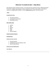
5.2 Jig Without Fullness
Using double sided tape, attach prepared template on to table, item 4. Select suitable 'Autotrak'
blank at least 50mm larger than card template round stitch line. Stick the two hinged plastic and
metal sheets together, i.e., the plastic to the metal to prevent it lifting during cutting. Stick the
blank on the table, metal side up. Ensure correct stylus is in position for cutting inner track (item
6 small). Switch on router. Holding handles of router move stylus so it touches template. Do not
allow stylus to move away from template. Wind down screw item 25 to allow cutter to cut
through both thicknesses of blank (plastic and metal) just sufficient to cut through so as not to
groove protection board excessively. Carefully cut inner track, see figure 1.0. Ensure contact of
stylus and template at all times. Any movement away from template will scrap blank. Track
should start 10mm before stitch line start and finish 20mm after. When complete wind cutter
clear of blank. Switch off motor.
4
Small Stylus
Item 6
Cutter
.
.
;
;
;
;
;
;
;
i
ct=[r
Master
! Template
;
;
!
"".."" "" ""..""::..~ ".:
!
! !
;
,
i;
;
j. ,,
.
.
;
i
~...L
;
;
Front of
Machine
)
.
'
CUTTING INNER TRACK (Fig 1.0)
84-78 June 1999
Page 5.0
.A~
F" REECE
_J3<tai Jdt£lJ...J3£ttci Jltade..-
5.3
5 Plastic Stitching Jigs
Cutting Outer Track
Loosen clamping screw then fit large stylus item 7, figure 1.1. Lower cutter just sufficiently to cut
through both thicknesses of blank so as not to groove protection board excessively.
router and holding router handles carefully feed cutter until stylus locates template.
Switch
on
Complete
outer profile and switch off.
Large Stylus
Item 7
Cutter
,
ri
,
;
;
;
;
;
;
;
:
Front of
Machine
Master
: Template
;
;
;
;
(i
CUTTING OUTER TRACK (Fig 1.1)
5.4
Finishing The Jig:
The Autojig stop pillar can now be added. The 4.5mm hole for the stop pillar is drilled
approximately 13mm from the edge of the track and the following distance past the end of the
stitch line :AJ52MP/MJ, AJ54UP/UJ =
22mm
84-19 MP & 84-23MP
22mm
84-19
AJ50 EP/EJ
=
= 35mm
= 35mm
The hole is drilled through and then countersunk from underneath the jig just sufficiently to
ensure that the head of the screw does not project below the underside of the jig.
For use on microprocessor-controlled Autojig machines black tape patches must be positioned
appropriately on the outer track to control cornering function. If desired, plastic location pegs may
be fitted, projecting through holes in the Aluminium top-plate, to assist in speedy loading of
cloth pieces into the jig.
Finally, remove any sharp edges on both the Aluminium and the PVC base plate.
84-78 June 1999
Page 5.2
.A~
F'") REECE
Jx/toi
JrU£l!..J3ettot ?llaeiL
5 Plastic Stitching Jigs
5.5. Jig With Fullness
The manufacture of a jig with fullness is essentially the same as without fullness except for the
extra operation of cutting the aperture in the top metal plate for the fulling bar, see figure 1.2.
Fulling Bar
Cutout
JIG TOP PLATE Fig
For the jig with fullness, the template should be prepared with a fullness cut out for the stylus to
follow, see figure 1.3. The shape of this cut out is determined by the setting of oddleg scribers to
the width required between the fulling bar and edge of template. Scribe round the edges of the
template and draw a line parallel to the hinge line to give required width of fulling bar. Make an
allowance for difference between cutter and stylus.
L
j
Fulling Cutout
Templat
Fig 1.3
Cut inner and outside track of jig exactly as described for jig without fulling.
completed, the following should be followed:
When this is
1.
Part the top and bottom plate of jig being made, remove double sided adhesive. Stick 1/8
thick packing on to top of bottom plate using double sided tape. Stick top plate to packing
to leave gap between plates. This gives clearance for cutter and does not cut fulling hinge.
2.
Fit small stylus item 6. Position stylus in fulling cut out in template pressing stylus to side of
template cut out. Start router cutter, lower cutter sufficiently to cut through top plate only.
Carefully cut out. When complete switch off router.
3.
The fulling bar is made from 3mm PVC - same material as jig bottom plate. The shape can
be taken from cut out in top plate of jig. Mark off on the PVC leaving the desired clearance
(dependent on material being sewn). Cut to shape using jig saw supplied with Autotrak.
Trim and smooth edge to remove sharp or rough edges. Close the lid of jig and stick some
strong double sided tape on the part of fullness hinge that shows. Position fulling bar in
center of cut out and stick to hinge. Trim off excessive hinge with knife.
84-78 June 1999
Page 5.2
.A'"
F"' REECE
_.L3{'R'C1~Jdct:l6, AtLtfY!
Jl1adLm
6 Tufnol Stitching Jigs
6 Manufacturing Stitching Jigs in Tufnol Phenolic Resin Laminate Material
6.1 Equipment Required:
Hardboard - 3.2mm thick
Aluminium- 1.5mm thick
Pop rivets - 2.3mm diameter
Drill - 2.3mm diameter
Template card - 2mm thick
Hinge
Fullness plate
Location plate
Jig stop pillarand screw
Double-sided tape
6.5mm diameter drill
6.2 Cutting Out Master Template
The 'master' is a hardboard template of the stitch line pattern.
Select a piece of hardboard which is just larger than the pattern all round except where the top
plate is to be hinged to the base plate, and this will need approximately 60mm of extra board.
Place the pattern on the board and scribe round it, continuingthe stitch line for a further 60mm at
the beginning and the end of the stitch line. Calculate the amount of fullness required and mark
out this required amount on to the board.
Using the jigsaw, carefullycut around the stitch line. Then cut out the aperture for the fullness by
first drillinga few holes and then using the jigsaw; starting by inserting the blade into the gap
made by the drilling,cut inside the scribed line.
Finally, finish the Master by carefully filing the edges down to the scribed outline.
6.3 Cutting Out The Base Plate
Using double sided tape stick prepared master to table 4, page 7.0. Select a piece of Tufnol
which is at least 50mm larger than the template on all sides, except the edge where the top plate
is to be hinged. Stick blank material on to table 5, page 7.0, in preparation for cutting. Ensure
correct stylus is fitted item 6, page 7.0, small 9.5mm. Switch on router. Holding handles of router
move so stylus touches template. Do not allow stylus to move away from template and wind
down screw item 25, page 7.0, just sufficient to allow cutter to cut through blank. To cut deeper
will unnecessarily groove protection board. Carefully cut inner track ensuring stylus contact with
template at all times. Any movement of stylus from template will scrap blank. Track should start
10mm before stitch line and finish 20mm after. When complete wind cutter clear of blank and
switch off. Remove small stylus and replace with large one item 7, page 7.0, for outer track.
Proceed as before cutting outer track, the only difference being cutting runs out at both start and
finish of cut.
84-78 June 1999
Page 6.0
.A~
F"' REECE
_fia:I&i~ JdC[J;J,At.ttf/! JlladL
6.4
6 Tufnol Stitching Jigs
Cutting Aluminium Top Plate
Select a piece of 1.5mm Aluminium sheet that is 20mm larger than the template around stitch
line. Note should be taken to ensure there is sufficient material in hinge area.
Position the blank to ensure the back position for the hinge is in the same relative position as that
of the Tufnol template cut at paragraph 6.3. Proceed to cut profile as paragraph 6.3. The fullness
aperture can now be cut still using small stylus. Once again ensure stylus stays in contact with
template.
6.5
Cutting Fullness Plate
The fullness bar is made from the Tufnol sheet. Using the top plate as a guide, mark out the
shape of the aperture on the Tufnol but make it sufficiently smaller all round to allow for the
material. Cut the shape out with the jigsaw by carefully following the line. Finally smooth the
edges down with a file.
6.6
Jig Assembly
The final stage in the manufacture of the jig is to assemble the base plate, top plate and fulling
bar together.
First cut a piece of hinge to the required length. Position the top plate over the base plate so that
its edges are in line with the inner edges of the inner track. Mark out the position of the hinge
relative to the hinged edge of the top plate. With the top plate and hinge in position, cut a piece of
steel plate approximately 50mm wide (smaller for narrower jigs and larger for wider jigs), and long
enough to be able to fasten on to the fulling bar and the hinge. Mark out the width of this plate on the
top arm of the hinge and centrally from each end. With two saw cuts relieve a part
of the hinge
in between the marking off so that the plate is hinged independently of the top plate.
Next, fasten the hinge to the base plate by drilling through both of them, countersinking the holes
from the underside of the base plate so the rivets do not protrude and then finally rivet the two
together. Then fasten the fulling plate to the cut out piece of hinge, again by drilling and riveting.
Next, line the top plate up with the edge of the inner track and fasten it to the hinge with sufficient
rivets, depending on its size. With the top plate down, place the fulling bar centrally into its
aperture. Mark its position on the steel hinge plate, and then fasten the two together again by
drilling and riveting.
If locating pegs are required for positioning the material, mark out their required positions on the
base plate and drill with a 2.4mm diameter drill. Countersink the holes from the underside of the
base plate. Next close the top plate and mark through the holes their positions on the top plate.
Drill the top plate in the marked positions with a 6.5mm diameter drill. Push the location pegs
into the holes in the base plate and fix in position by peening the ends over with a hammer.
6.7.1
Finishing The Jig:
84-50EP/EJ ONLY
The stop pillar and the green baize can now be added.
6.7.2
FINISHING THE JIG:
84-52MP/MJ AND 84-54UP/UJ Autojig Machines
Attach the green baize as the 84-50E and 84-52S jigs. Stick black self-adhesive tape to the jig in
the required position at the end of the track for the photocell to sense and stop sewing.
84-78 June 1999
Page 6.0