1
hp LaserJet 9055 mfp
hp LaserJet 9065 mfp
service manual
hp LaserJet 9055mfp (Q3631A)
hp LaserJet 9065mfp (Q3632A)
service manual
Copyright Information
Trademark Credits
© 2003 Copyright Hewlett-Packard Development
Company, L.P.
Microsoft®, Windows®, and Windows NT® are
U.S. registered trademarks of Microsoft
Corporation.
Reproduction, adaptation or translation without
prior written permission is prohibited, except as
allowed under the copyright laws.
The information contained herein is subject to
change without notice.
The only warranties for HP products and services
are set forth in the express warranty statements
accompanying such products and services.
Nothing herein should be construed as
constituting an additional warranty. HP shall not be
liable for technical or editorial errors or omissions
contained herein.
Part number: Q3631-90908
Edition 1, 11/2003
1 How to use this manual
Manual contents . . . . . . . . . . . . . . . . . . . . . . . . . 2
Manual organization . . . . . . . . . . . . . . . . . . . . . . 2
2 Safety
Safety and important warning items . . . . . . . . . . 4
Important notices. . . . . . . . . . . . . . . . . . . . . 4
Description items for Warning, Caution,
and Note . . . . . . . . . . . . . . . . . . . . . . . 4
Safety warnings. . . . . . . . . . . . . . . . . . . . . . . . . . 5
Modifications not authorized by hp . . . . . . . 5
Power supply. . . . . . . . . . . . . . . . . . . . . . . . 7
Installation requirements . . . . . . . . . . . . . . 10
Measures to take in case of an accident. . 15
Conclusion . . . . . . . . . . . . . . . . . . . . . . . . 15
Regulatory statements . . . . . . . . . . . . . . . . . . . 16
Safety information . . . . . . . . . . . . . . . . . . . . . . . 16
Safety circuits . . . . . . . . . . . . . . . . . . . . . . 16
Overall protection circuit . . . . . . . . . . . . . . 16
Safety labels on the MFPs . . . . . . . . . . . . . . . . 19
Scanner section . . . . . . . . . . . . . . . . . . . . 21
Laser/scanner assembly . . . . . . . . . . . . . . 21
Rear cover. . . . . . . . . . . . . . . . . . . . . . . . . 21
3 MFP overview
Overview of system . . . . . . . . . . . . . . . . . . . . . . 24
hp LaserJet 9055mfp/9065mfp product
specifications. . . . . . . . . . . . . . . . . . . . . . . 25
Type . . . . . . . . . . . . . . . . . . . . . . . . . . . . . 25
Functions. . . . . . . . . . . . . . . . . . . . . . . . . . 25
Applicable copy paper. . . . . . . . . . . . . . . . 26
Options . . . . . . . . . . . . . . . . . . . . . . . . . . . 26
Particulars of machine. . . . . . . . . . . . . . . . 26
Maintenance and life . . . . . . . . . . . . . . . . . 26
Environmental conditions . . . . . . . . . . . . . 26
Central cross-sectional view . . . . . . . . . . . . . . . 27
Drive system diagram . . . . . . . . . . . . . . . . . . . . 28
Fuser/web drive section . . . . . . . . . . . . . . 28
Drum drive section . . . . . . . . . . . . . . . . . . 29
Developing drive section . . . . . . . . . . . . . . 29
Paper feed/vertical conveyance/tray
up drive sections . . . . . . . . . . . . . . . . 30
ENWW
Tray 1 paper feed/automatic duplex
unit (ADU) pre-registration
drive section . . . . . . . . . . . . . . . . . . . 31
Charging and transfer/separation wire
cleaning drive section . . . . . . . . . . . . 32
Automatic Duplex Unit (ADU)
conveyance drive section . . . . . . . . . 33
Paper exit drive section . . . . . . . . . . . . . . 34
Toner supply drive section . . . . . . . . . . . . 34
Optics drive section . . . . . . . . . . . . . . . . . 35
4 MFP unit explanation
External section . . . . . . . . . . . . . . . . . . . . . . . . 40
Composition . . . . . . . . . . . . . . . . . . . . . . . 40
Drive section . . . . . . . . . . . . . . . . . . . . . . . . . . . 41
Composition . . . . . . . . . . . . . . . . . . . . . . . 41
Mechanisms . . . . . . . . . . . . . . . . . . . . . . . 41
M2 (drum) control . . . . . . . . . . . . . . . . . . . 42
M4 (fuser) control . . . . . . . . . . . . . . . . . . . 42
Scanner section . . . . . . . . . . . . . . . . . . . . . . . . 44
Composition . . . . . . . . . . . . . . . . . . . . . . . 44
Mechanisms . . . . . . . . . . . . . . . . . . . . . . . 44
M11 (scanner) control. . . . . . . . . . . . . . . . 45
Exposure control. . . . . . . . . . . . . . . . . . . . 48
Original read control . . . . . . . . . . . . . . . . . 48
APS control. . . . . . . . . . . . . . . . . . . . . . . . 49
AE control . . . . . . . . . . . . . . . . . . . . . . . . . 51
Laser scanner unit . . . . . . . . . . . . . . . . . . . . . . 52
Composition . . . . . . . . . . . . . . . . . . . . . . . 52
Mechanisms . . . . . . . . . . . . . . . . . . . . . . . 52
M15 (polygon) control . . . . . . . . . . . . . . . . 53
Image write control . . . . . . . . . . . . . . . . . . 53
Drum unit . . . . . . . . . . . . . . . . . . . . . . . . . . . . . 56
Composition . . . . . . . . . . . . . . . . . . . . . . . 56
Mechanisms . . . . . . . . . . . . . . . . . . . . . . . 56
Separation claw control . . . . . . . . . . . . . . 57
Paper guide plate control . . . . . . . . . . . . . 57
Corona unit section . . . . . . . . . . . . . . . . . . . . . . 58
Composition . . . . . . . . . . . . . . . . . . . . . . . 58
Mechanisms . . . . . . . . . . . . . . . . . . . . . . . 58
Charging control . . . . . . . . . . . . . . . . . . . . 58
Transfer/separation control. . . . . . . . . . . . 59
iii
Contents
Contents
M14 (charger cleaning) control . . . . . . . . . 60
M10 (transfer/separation cleaning)
control . . . . . . . . . . . . . . . . . . . . . . . . 61
PCL/TSL control . . . . . . . . . . . . . . . . . . . . 62
Developing unit . . . . . . . . . . . . . . . . . . . . . . . . . 63
Composition . . . . . . . . . . . . . . . . . . . . . . . 63
Mechanisms . . . . . . . . . . . . . . . . . . . . . . . 63
M3 (developing) control. . . . . . . . . . . . . . . 63
Developing bias control. . . . . . . . . . . . . . . 64
Dmax (maximum contrast) control . . . . . . 65
Gradation correction control . . . . . . . . . . . 67
Dot diameter correction control . . . . . . . . . 68
Toner density control. . . . . . . . . . . . . . . . . 69
FM4 (developing suction) control . . . . . . . 69
Toner supply unit. . . . . . . . . . . . . . . . . . . . . . . . 70
Composition . . . . . . . . . . . . . . . . . . . . . . . 70
Mechanisms . . . . . . . . . . . . . . . . . . . . . . . 70
Toner level detection control . . . . . . . . . . . 71
M12 (toner supply) control . . . . . . . . . . . . 72
Cleaning/toner recycle unit . . . . . . . . . . . . . . . . 73
Composition . . . . . . . . . . . . . . . . . . . . . . . 73
Mechanisms . . . . . . . . . . . . . . . . . . . . . . . 73
Toner guide roller (TGR) control . . . . . . . . 74
Other control . . . . . . . . . . . . . . . . . . . . . . . 74
Tray 2/3 paper feed unit . . . . . . . . . . . . . . . . . . 75
Composition . . . . . . . . . . . . . . . . . . . . . . . 75
Mechanisms . . . . . . . . . . . . . . . . . . . . . . . 75
First paper feed control . . . . . . . . . . . . . . . 77
Paper up drive control . . . . . . . . . . . . . . . . 79
Paper size detection control . . . . . . . . . . . 80
No paper detection control . . . . . . . . . . . . 81
Tray 4 paper feed unit . . . . . . . . . . . . . . . . . . . . 82
Composition . . . . . . . . . . . . . . . . . . . . . . . 82
Mechanisms . . . . . . . . . . . . . . . . . . . . . . . 82
First paper feed control . . . . . . . . . . . . . . . 84
Paper up drive control . . . . . . . . . . . . . . . . 86
Paper size detection control . . . . . . . . . . . 87
No paper detection control . . . . . . . . . . . . 87
Tray 1 (bypass tray) . . . . . . . . . . . . . . . . . . . . . 89
Composition . . . . . . . . . . . . . . . . . . . . . . . 89
Mechanisms . . . . . . . . . . . . . . . . . . . . . . . 89
First paper feed control . . . . . . . . . . . . . . . 90
Paper up/down control . . . . . . . . . . . . . . . 90
Paper size detection control . . . . . . . . . . . 91
No paper detection control . . . . . . . . . . . . 92
Vertical conveyance section . . . . . . . . . . . . . . . 93
Composition . . . . . . . . . . . . . . . . . . . . . . . 93
Mechanisms . . . . . . . . . . . . . . . . . . . . . . . 93
Vertical conveyance control . . . . . . . . . . . 93
Automatic duplex unit (ADU) . . . . . . . . . . . . . . . 95
Composition . . . . . . . . . . . . . . . . . . . . . . . 95
Mechanisms . . . . . . . . . . . . . . . . . . . . . . . 96
Loop/second paper feed control . . . . . . . 101
Paper conveyance control. . . . . . . . . . . . 103
iv
Paper reverse and exit control . . . . . . . . 104
ADF paper conveyance/feed control . . . 108
Fuser unit . . . . . . . . . . . . . . . . . . . . . . . . . . . . 111
Composition . . . . . . . . . . . . . . . . . . . . . . 111
Mechanisms . . . . . . . . . . . . . . . . . . . . . . 111
M16 (web drive) control . . . . . . . . . . . . . 113
Fuser temperature control . . . . . . . . . . . 114
Other kinds of control . . . . . . . . . . . . . . . . . . . 116
Parts energized when SW1 (main
power) is off . . . . . . . . . . . . . . . . . . 116
Parts that operate when SW1 (main
power)/SW2 (secondary power)
is on . . . . . . . . . . . . . . . . . . . . . . . . 117
Cooling fan control . . . . . . . . . . . . . . . . . 118
Control panel control. . . . . . . . . . . . . . . . 122
Counter control . . . . . . . . . . . . . . . . . . . . 124
Option control . . . . . . . . . . . . . . . . . . . . . 126
5 MFP disassembly/assembly
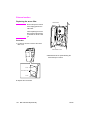
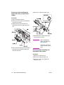
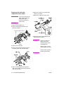
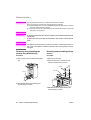
External section . . . . . . . . . . . . . . . . . . . . . . . 132
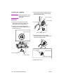
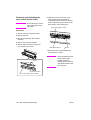
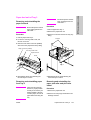
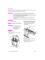
Replacing the ozone filter . . . . . . . . . . . . 132
Replacing the developing suction filter . . 133
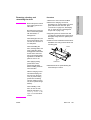
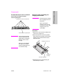
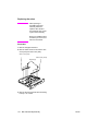
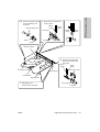
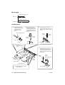
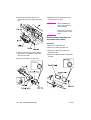
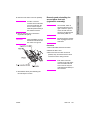
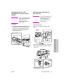
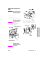
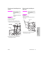
Removing and reinstalling the
external covers . . . . . . . . . . . . . . . . 133
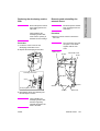
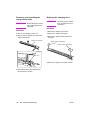
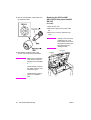
Changing the control panel
attachment angle and
removing/reinstalling. . . . . . . . . . . . 136
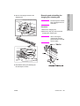
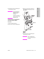
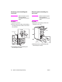
Resetting the circuit breaker . . . . . . . . . . 137
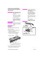
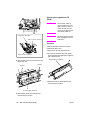
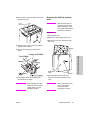
Drive section . . . . . . . . . . . . . . . . . . . . . . . . . . 138
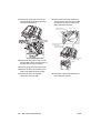
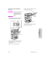
Removing and reinstalling the drum
motor (M2) . . . . . . . . . . . . . . . . . . . 138
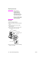
Removing and reinstalling the fusing
input gear . . . . . . . . . . . . . . . . . . . . 140
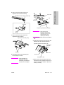
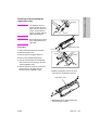
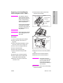
Scanner section . . . . . . . . . . . . . . . . . . . . . . . 141
Screws that must not be removed . . . . . 141
Removing and reinstalling the CCD
unit . . . . . . . . . . . . . . . . . . . . . . . . . 141
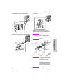
Replacing the exposure lamp . . . . . . . . . 142
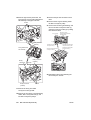
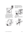
Removing and reinstalling the
exposure unit . . . . . . . . . . . . . . . . . 143
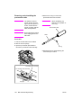
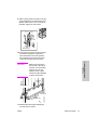
Installing the optics wire . . . . . . . . . . . . . 145
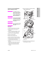
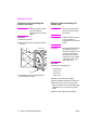
Cleaning the ADF glass and scanner
glass . . . . . . . . . . . . . . . . . . . . . . . . 147
Replacing the scanner motor (M11) . . . 148
Laser scanner unit . . . . . . . . . . . . . . . . . . . . . 150
Removing and reinstalling the laser/
scanner assembly. . . . . . . . . . . . . . 150
Cleaning the dust-proof glass . . . . . . . . . 151
Drum unit . . . . . . . . . . . . . . . . . . . . . . . . . . . . 152
Removing and reinstalling the drum
unit . . . . . . . . . . . . . . . . . . . . . . . . . 152
Installing the coupling . . . . . . . . . . . . . . . 154
ENWW
ENWW
Paper feed unit of Tray 3 . . . . . . . . . . . . . . . . 179
Removing and reinstalling the paper
feed unit . . . . . . . . . . . . . . . . . . . . . 179
Removing and reinstalling paper feed
Tray 3 . . . . . . . . . . . . . . . . . . . . . . . 179
Removing and reinstalling the paper
pick roller and pick roller rubber . . . 179
Removing and reinstalling the
separation roller rubber. . . . . . . . . . 180
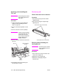
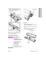
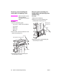
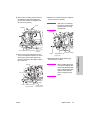
Replacing the pre-registration and feed
clutches (MCs) . . . . . . . . . . . . . . . . 181
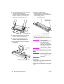
Replacing the wires . . . . . . . . . . . . . . . . 182
Wire lengths . . . . . . . . . . . . . . . . . . . . . . 183
Installing wires . . . . . . . . . . . . . . . . . . . . 184
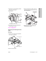
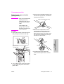
Tray 1 . . . . . . . . . . . . . . . . . . . . . . . . . . . . . . . 185
Removing and reinstalling Tray 1 . . . . . . 185
Replacing the paper pick roller/paper
pick roller rubber . . . . . . . . . . . . . . . 185
Replacing the separation roller rubber . . 186
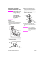
Vertical conveyance section . . . . . . . . . . . . . . 187
Removing and reinstalling the vertical
conveyance section . . . . . . . . . . . . 187
Removing and reinstalling the vertical
conveyance MC (MC11, MC12) . . . 187
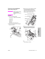
ADF unit . . . . . . . . . . . . . . . . . . . . . . . . . . . . . 188
Pulling out and reinstalling the ADU
stand . . . . . . . . . . . . . . . . . . . . . . . . 188
Cleaning the paper mis-centering PS
(PS70)/leading edge PS (PS43) . . . 189
Removing and reinstalling the
registration MC (MC1) . . . . . . . . . . 190
Removing and reinstalling the
second paper feed unit
(registration assembly) . . . . . . . . . . 191
Cleaning the registration PS (PS44). . . . 192
Removing and reinstalling the
registration roller . . . . . . . . . . . . . . . 193
Removing and reinstalling the
pre-transfer roller . . . . . . . . . . . . . . 194
Cleaning the automatic document
feeder paper reverse PS (PS45)/
Reverse/Exit PS (PS46) . . . . . . . . . 195
Removing and reinstalling the ADF
reverse roller. . . . . . . . . . . . . . . . . . 198
Removing and reinstalling the ADU
stand . . . . . . . . . . . . . . . . . . . . . . . . 199
Removing and reinstalling the
pre-registration roller. . . . . . . . . . . . 201
Removing and reinstalling the ADU
conveyance roller 3 and 4. . . . . . . . 202
Removing and reinstalling the ADU
conveyance roller 1 and 2. . . . . . . . 205
Removing and reinstalling the paper
reverse/exit roller . . . . . . . . . . . . . . 207
v
Contents
Removing, cleaning, and reinstalling
the drum . . . . . . . . . . . . . . . . . . . . . 155
Removing and reinstalling the
separation claws and separation
claw solenoid . . . . . . . . . . . . . . . . . 156
Removing and reinstalling the toner
control sensor board . . . . . . . . . . . . 158
Corona unit . . . . . . . . . . . . . . . . . . . . . . . . . . . 159
Screws that must not be removed. . . . . . 159
Removing and reinstalling the charging
corona unit . . . . . . . . . . . . . . . . . . . 159
Removing and reinstalling the charge
control plate . . . . . . . . . . . . . . . . . . 160
Replacing the charging wires . . . . . . . . . 160
Removing and reinstalling the
charging wire cleaning unit . . . . . . . 161
Removing and reinstalling the PCL. . . . . 162
Cleaning the charging corona unit/PCL . 163
Removing and reinstalling the
transfer/separation corona unit . . . . 163
Removing and reinstalling the plunger
prevention plate . . . . . . . . . . . . . . . 164
Replacing the transfer/separation
wires and transfer/separation
wire cleaning block . . . . . . . . . . . . . 164
Removing and reinstalling the TSL unit . 166
Developing unit . . . . . . . . . . . . . . . . . . . . . . . . 166
Screws that must not be removed. . . . . . 166
Removing and reinstalling the
developing unit . . . . . . . . . . . . . . . . 166
Replacing the developer . . . . . . . . . . . . . 167
Cleaning the developing unit bias shaft . 168
Toner supply unit. . . . . . . . . . . . . . . . . . . . . . . 169
Replacing and cleaning the toner
bottle . . . . . . . . . . . . . . . . . . . . . . . . 169
Cleaning/toner recycle unit . . . . . . . . . . . . . . . 170
Removing and reinstalling the
cleaning blade . . . . . . . . . . . . . . . . . 170
Removing and reinstalling the toner
guide roller (TGR) . . . . . . . . . . . . . . 171
Paper feed units of Trays 2 and 3 . . . . . . . . . . 173
Removing and reinstalling the paper
feed unit . . . . . . . . . . . . . . . . . . . . . 173
Removing and reinstalling the paper
feed Trays 2 and 3 . . . . . . . . . . . . . 173
Removing and reinstalling the paper
pick roller and pick roller rubber . . . 174
Removing and reinstalling the
separation roller rubber . . . . . . . . . . 174
Replacing the pre-registration and feed
clutches (MCs) . . . . . . . . . . . . . . . . 175
Replacing the wires. . . . . . . . . . . . . . . . . 176
Wire lengths . . . . . . . . . . . . . . . . . . . . . . 178
Installing wires. . . . . . . . . . . . . . . . . . . . . 178
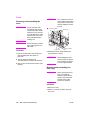
Fuser . . . . . . . . . . . . . . . . . . . . . . . . . . . . . . . . 208
Removing and reinstalling the fuser . . . . 208
Removing and reinstalling the fuser
(top). . . . . . . . . . . . . . . . . . . . . . . . . 208
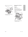
Removing and reinstalling the web
cover . . . . . . . . . . . . . . . . . . . . . . . . 209
Removing and reinstalling the
cleaning web . . . . . . . . . . . . . . . . . . 210
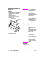
Replacing the fusing heater lamps
(L2, L3) . . . . . . . . . . . . . . . . . . . . . . 210
Replacing the fusing heater lamp (L4) . . 212
Removing and reinstalling the fusing
separation claw (upper) unit and
fusing separation claws (upper) . . . 213
Removing and reinstalling the fusing
separation claw (lower) unit and
fusing separation claws (lower). . . . 214
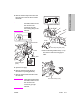
Removing and reinstalling the fusing
upper roller . . . . . . . . . . . . . . . . . . . 214
Removing and reinstalling the fusing
lower roller . . . . . . . . . . . . . . . . . . . 215
Removing and reinstalling the
decurler roller . . . . . . . . . . . . . . . . . 216
Removing and reinstalling the fusing
temperature sensors 1 and 2 . . . . . 217
Removing and reinstalling the
thermostat/U (TS1) . . . . . . . . . . . . . 218
Removing and reinstalling the
thermostat/L (TS2) . . . . . . . . . . . . . 220
6 Product comparison
hp LaserJet 9055mfp/9065mfp list of
differences. . . . . . . . . . . . . . . . . . . . . . . . 224
A Environmental Product
Stewardship Program
Environmental Product Stewardship
Program . . . . . . . . . . . . . . . . . . . . . . . . . 226
Protecting the environment . . . . . . . . . . . 226
B Terminology cross-reference
Terminology cross-reference for the MFP. . . . 228
Index
vi
ENWW
How to use this manual
1
How to use this
manual
Manual contents . . . . . . . . . . . . . . . . . . . . . . . . . . . . . . . . . . . . . . . . . . . . . . . . 2
Manual organization . . . . . . . . . . . . . . . . . . . . . . . . . . . . . . . . . . . . . . . . . . . . . 2
ENWW
1
Manual contents
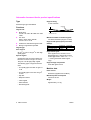
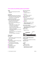
The HP LaserJet 9055mfp/9065mfp Service Manual contains six separate documents. Each
document provides specific service information for one of the components that make up the
HP LaserJet 9055mfp/9065mfp. The following are the component documents, listed in the order
that they appear in the manual:
●
HP LaserJet 9055mfp/9065mfp (main engine)
●
Automatic document feeder
●
4000-sheet high capacity input
●
Post insertion kit
●
Punch kit
●
Stapler/stacker and multifunction finisher
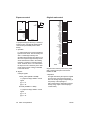
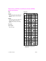
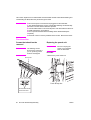
Manual organization
Each separate document contains its own table of contents and index. The tabs on the
right-hand pages help you identify the sections of the manual. The tab for the table of contents
in each document appears in magenta. The tabs for the remaining chapters in each document
appear in gray.
2 How to use this manual
ENWW
Safety
Safety and important warning items . . . . . . . . . . . . . . . . . . . . . . . . . . . . . . . . . 4
Important notices . . . . . . . . . . . . . . . . . . . . . . . . . . . . . . . . . . . . . . . . . . . 4
Description items for Warning, Caution, and Note . . . . . . . . . . . . . . . . . . 4
Safety warnings . . . . . . . . . . . . . . . . . . . . . . . . . . . . . . . . . . . . . . . . . . . . . . . . 5
Modifications not authorized by hp. . . . . . . . . . . . . . . . . . . . . . . . . . . . . . 5
Power supply . . . . . . . . . . . . . . . . . . . . . . . . . . . . . . . . . . . . . . . . . . . . . . 7
Installation requirements . . . . . . . . . . . . . . . . . . . . . . . . . . . . . . . . . . . . 10
Measures to take in case of an accident . . . . . . . . . . . . . . . . . . . . . . . . 15
Conclusion . . . . . . . . . . . . . . . . . . . . . . . . . . . . . . . . . . . . . . . . . . . . . . . 15
Regulatory statements . . . . . . . . . . . . . . . . . . . . . . . . . . . . . . . . . . . . . . . . . . 16
Safety information . . . . . . . . . . . . . . . . . . . . . . . . . . . . . . . . . . . . . . . . . . . . . 16
Safety circuits. . . . . . . . . . . . . . . . . . . . . . . . . . . . . . . . . . . . . . . . . . . . . 16
Overall protection circuit. . . . . . . . . . . . . . . . . . . . . . . . . . . . . . . . . . . . . 16
Safety labels on the MFPs . . . . . . . . . . . . . . . . . . . . . . . . . . . . . . . . . . . . . . . 19
Scanner section . . . . . . . . . . . . . . . . . . . . . . . . . . . . . . . . . . . . . . . . . . . 21
Laser/scanner assembly . . . . . . . . . . . . . . . . . . . . . . . . . . . . . . . . . . . . 21
Rear cover . . . . . . . . . . . . . . . . . . . . . . . . . . . . . . . . . . . . . . . . . . . . . . . 21
ENWW
3
Safety
2
Safety and important warning items
Read carefully the safety and important warning items described below to understand them
before doing service work.
Important notices
Because of possible hazards to an inexperienced person servicing this MFP as well as the risk
of damage to the MFP, HP strongly recommends that all servicing be performed only by
HP-trained service technicians.
Changes may have been made to this MFP to improve its performance after this service
handbook was printed. Accordingly, HP does not warrant, either explicitly or implicitly, that the
information contained in this service handbook is complete and accurate.
The user of this service handbook must assume all risks of personal injury and/or damage to
the MFP while servicing the MFP for which this service handbook is intended.
Therefore, this service handbook must be carefully read before doing service work both in the
course of technical training and even after that, for performing maintenance and control of the
MFP properly.
Keep this service handbook also for future service.
When it is impossible to read the description about safety and warnings (due to contamination
or tear), the relevant page should be replaced.
Description items for Warning, Caution, and Note
In this service handbook, Warning, Caution, and Note are defined as follows together with a
symbol mark to be used in a limited meaning.
When servicing the MFP, the relevant works (disassembling, reassembling, adjustment, repair,
maintenance, and so forth) need to be conducted with utmost care.
WARNING!
Warning messages alert the reader to a specific procedure or practice which,
if not followed correctly, could cause personal injury or catastrophic loss of data
or equipment.
CAUTION
Caution messages appear before procedures which, if not observed, could
result in loss of data or damage to equipment
Note
4 Safety
Notes contain important information.
ENWW
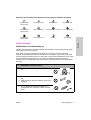
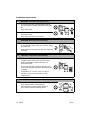
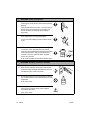
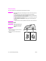
Symbols used for safety and important warning items are defined as follows
Precaution when
using the MFP
General precaution
Electric hazard
High temperature
Prohibition when
using the MFP
General prohibition
Do not touch with wet hand
Do not disassemble
Direction when
using the MFP
General instruction
Unplug
Ground/Earth
Safety
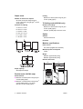
Safety warnings
Modifications not authorized by hp
HP MFPs are renowned for their high reliability. This reliability is achieved through high-quality
design and a solid service network.
MFP design is a highly complicated and delicate process where numerous mechanical,
physical, and electrical aspects have to be taken into consideration, with the aim of arriving at
proper tolerances and safety factors. For this reason, unauthorized modifications involve a high
risk of degradation in performance and safety. Such modifications are therefore strictly
prohibited. The points listed below are not exhaustive, but they illustrate the reasoning behind
this policy.
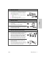
WARNING: Prohibited actions
●
Do not use any cables or power cord not specified by
HP.
●
Do not use any fuse or thermostat not specified by
HP.
●
Safety will not be assured, leading to a risk of fire
and injury.
●
Do not disable fuse functions or bridge fuse
terminals with wire, metal clips, solder, or similar
object.
ENWW
Safety warnings 5
WARNING: Prohibited actions
●
Do not disable relay functions (such as wedging
paper between relay contacts).
●
Do not disable safety functions (interlocks, safety
circuits, and so forth). Safety will not be assured,
leading to a risk of fire and injury.
●
Do not make any modification to the MFP unless
instructed by HP.
●
Do not use parts not specified by HP.
Note
Only qualified service personnel should disable relay functions and safety functions
when it is necessary to solve problems.
Checkpoints when performing on-site service
HP MFPs are extensively tested before shipping to ensure that all applicable safety standards
are met, and to protect the customer and customer engineer (hereafter called the CE) from the
risk of injury. However, in daily use, any electrical equipment may be subject to parts wear and
eventual failure. In order to maintain safety and reliability, the CE must perform regular safety
checks.
6 Safety
ENWW
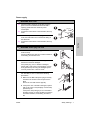
Power supply
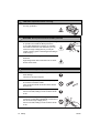
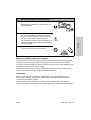
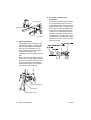
WARNING: Wall outlet
Check that main voltage is as specified. Plug the
power cord into the dedicated wall outlet with a
capacity greater than the maximum power
consumption.
●
If excessive current flows in the wall outlet, fire may
result.
●
If two or more power cords are plugged into the wall
outlet, the total load must not exceed the rating of
the wall outlet.
●
If excessive current flows in the wall outlet, fire may
result.
kw
Safety
●
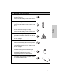
WARNING: Power plug and cord
●
Make sure the power cord is plugged in the wall
outlet securely.
Contact problems may lead to increased resistance,
overheating, and the risk of fire.
●
Check whether the power cord is damaged. Check
whether the sheath is damaged.
If the power plug, cord, or sheath is damaged,
replace with a new power cord (with plugs on both
ends) specified by HP. Using the damaged power
cord may result in fire or electric shock.
●
When using the power cord (inlet type) that came
with this MFP, be sure to observe the following
precautions:
a Make sure the MFP-side power plug is securely
inserted in the socket on the rear panel of the
MFP.
Secure the cord with a fixture properly.
b If the power cord or sheath is damaged, replace
with a new power cord (with plugs on both ends)
specified by HP.
If the power cord (inlet type) is not connected to
the MFP securely, a contact problem may lead to
increased resistance, overheating, and risk of
fire.
ENWW
Safety warnings 7
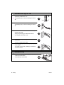
WARNING: Power plug and cord
●
Check whether the power cord is not stepped on or
pinched by a table and so on.
●
Overheating may occur there, leading to a risk of
fire.
●
Do not bundle or tie the power cord.
Overheating may occur there, leading to a risk of
fire.
●
Check whether dust has collected around the power
plug and wall outlet.
Using the power plug and wall outlet without
removing dust may result in fire.
●
Do not insert the power plug into the wall outlet with
a wet hand.
The risk of electric shock exists.
●
When unplugging the power cord, grasp the plug,
not the cable.
The cable may be broken, leading to a risk of fire
and electric shock.
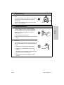
WARNING: Wiring
●
Never use multi-plug adapters to plug multiple power
cords in the same outlet.
If used, the risk of fire exists.
8 Safety
ENWW
WARNING: Wiring
●
When an extension cord is required, use a specified
one.
Current that can flow in the extension cord is limited,
so using an extension cord that is too long may
result in fire.
Do not use an extension cable reel with the cable
taken up. Fire may result.
WARNING: Ground lead
Check whether the MFP is grounded properly.
If current leakage occurs in an ungrounded MFP,
you may suffer electric shock while operating the
MFP. Connect the ground lead to one of the
following points:
Safety
●
a Ground terminal of wall outlet
b Ground terminal for which Class D work has been
done
●
Pay attention to the point where the ground lead is
connected.
Connecting the ground lead to an improper point as
listed below results in a risk of explosion and electric
shock:
a Gas pipe (A risk of explosion or fire exists.)
b Lightning rod (A risk of electric shock or fire
exists.)
c Telephone line ground (A risk of electric shock or
fire exists in the case of lightning.)
d Water pipe or faucet (It may include a plastic
portion.)
ENWW
Safety warnings 9
Installation requirements
WARNING: Prohibited installation place
●
Do not place the MFP near flammable materials
such as curtains or volatile materials that may catch
fire.
A risk of fire exists.
●
Do not place the MFP in a place exposed to water
such as rain water.
A risk of fire and electric shock exists.
WARNING: Non-operational handling
●
When the MFP is not used over an extended period
of time (holidays, and so forth), turn it off and unplug
the power cord.
Dust collected around the power plug and outlet may
cause fire.
CAUTION: Temperature and humidity
●
Do not place the MFP in a place exposed to direct
sunlight or near a heat source such as a heater.
A risk of degradation in MFP performance or
deformation exists.
Do not place the MFP in a place exposed to cool
wind. Recommended temperature and humidity are
as follows:
Temperature: 10° C to 30° C (50° F to 86° F)
Humidity: 10 percent to 80 percent (no dew
condensation)
CAUTION: Ventilation
●
10
Do not place the MFP in a place where there is much
dust, cigarette smoke, or ammonia gas.
Place the MFP in a well-ventilated location to
prevent MFP problems and image issues.
Safety
ENWW
CAUTION: Ventilation
●
The MFP generates ozone gas during operation, but
it is not sufficient to be harmful to the human body.
If a bad smell of ozone is present in the following
cases, ventilate the room.
●
When the MFP is used in a poorly ventilated
room
●
When making a lot of copies
●
When using multiple MFPs at the same time
CAUTION: Vibration
When installing the MFP, read the installation guide
thoroughly. Be sure to install the MFP on a level and
sturdy surface.
Safety
●
Constant vibration will cause problems.
●
Be sure to lock the caster stoppers.
In the case of an earthquake and so on, the MFP
may slide, leading to a injury.
CAUTION: Inspection before servicing
●
Before conducting an inspection, read all relevant
documentation (service handbook, technical notices,
and so forth) and proceed with the inspection
following the prescribed procedure in safety clothes,
using only the prescribed tools. Do not make any
adjustment not described in the documentation.
If the prescribed procedure or tool is not used, the
MFP may break and a risk of injury or fire exists.
●
Before conducting an inspection, be sure to
disconnect the power cords from the MFP and
optional accessories.
When the power plug is inserted in the wall outlet,
some units are still powered even if the power switch
is turned off. A risk of electric shock exists.
ENWW
Safety warnings
11
CAUTION: Inspection before servicing
●
The area around the fuser unit is hot.
You may get burned.
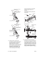
WARNING: Work performed with the MFP powered
●
Be careful when making adjustments or performing
an operation check with the MFP powered on.
If you make adjustments or perform an operation
check with the external cover detached, you may
touch live or high-voltage parts or you may be
caught in moving gears or the timing belt, leading to
a risk of injury.
●
Be careful when servicing with the external cover
detached.
High-voltage exists around the drum unit. A risk of
electric shock exists.
WARNING: Safety checkpoints
●
Check the exterior and frame for edges, burrs, and
other damage.
The user or CE may be injured.
●
Do not allow any metal parts such as clips, staples,
and screws to fall into the MFP.
They can short internal circuits and cause electric
shock or fire.
●
Check wiring for squeezing and any other damage.
Current can leak, leading to a risk of electric shock
or fire.
●
When disconnecting connectors, grasp the
connector, not the cable. (Specifically, connectors of
the AC line and high-voltage parts.)
Current can leak, leading to a risk of electric shock
or fire.
12
Safety
ENWW
WARNING: Safety checkpoints
●
Carefully remove all toner remnants and dust from
electrical parts and electrode units such as a
charging corona unit.
Current can leak, leading to a risk of MFP trouble or
fire.
●
Check high-voltage cables and sheaths for any
damage.
Current can leak, leading to a risk of electric shock
or fire.
Check electrode units such as a charging corona
unit for deterioration and sign of leakage.
Safety
●
Current can leak, leading to a risk of trouble or fire.
●
Before disassembling or adjusting the laser/scanner
assembly incorporating a laser, make sure that the
power cord has been disconnected.
The laser light can enter your eye, leading to a risk
of loss of eyesight.
●
Do not remove the cover of the laser/scanner
assembly. Do not supply power with the
laser/scanner assembly shifted from the specified
mounting position.
The laser light can enter your eye, leading to a risk
of loss of eyesight.
●
When replacing a lithium battery, replace it with a
new lithium battery specified in the parts guide
manual. Dispose of the used lithium battery using
the method specified by local authority.
Improper replacement can cause explosion.
●
After replacing a part to which AC voltage is applied
(for example, optical lamp and fuser lamp), be sure
to check the installation state.
A risk of fire exists.
ENWW
Safety warnings
13
WARNING: Safety checkpoints
●
Check the interlock switch and actuator for
loosening and check whether the interlock functions
properly.
If the interlock does not function, you may receive an
electric shock or be injured when you insert your
hand in the MFP (for example, when clearing a
paper jam).
●
Make sure the wiring cannot come into contact with
sharp edges, burrs, or other pointed parts.
Current can leak, leading to a risk of electric shock
or fire.
●
Make sure that all screws, components, wiring,
connectors, and so forth that were removed for
safety check and maintenance have been reinstalled
in the original location. (Pay special attention to
forgotten connectors, pinched cables, forgotten
screws, and so forth).
A risk of MFP trouble, electric shock, and fire exists.
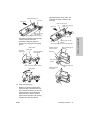
WARNING: Handling of service materials
●
Unplug the power cord from the wall outlet.
●
Drum cleaner (isopropyl alcohol) and roller cleaner
(acetone-based) are highly flammable and must be
handled with care. A risk of fire exists.
●
Do not replace the cover or turn the MFP on before
any solvent remnants on the cleaned parts have fully
evaporated.
A risk of fire exists.
●
Use only a small amount of cleaner at a time and
take care not to spill any liquid. If this happens,
immediately wipe it off.
A risk of fire exists.
14
Safety
ENWW
WARNING: Handling of service materials
●
When using any solvent, ventilate the room well.
Breathing large quantities of organic solvents can
lead to discomfort.
●
Toner and developer are not harmful substances,
but care must be taken not to breathe excessive
amounts or let the substances come into contact
with eyes, and so forth. It may be stimulative.
●
Safety
If the substances get in the eye, rinse with plenty of
water immediately. When symptoms are noticeable,
consult a physician.
Never throw the used toner bottle and toner into fire.
You may be burned due to dust explosion.
Measures to take in case of an accident
If an accident has occurred, the distributor who has been notified first must immediately take
emergency measures to provide relief to affected persons and to prevent further damage.
If a report of a serious accident has been received from a customer, an on-site evaluation must
be carried out quickly and HP must be notified.
To determine the cause of the accident, conditions and materials must be recorded through
direct on-site checks, in accordance with instructions issued by HP.
Conclusion
Safety of users and customer engineers depends highly on accurate maintenance and
administration. Therefore, safety can be maintained by the appropriate daily service work
conducted by the customer engineer.
When performing service, each MFP on the site must be tested for safety. The customer
engineer must verify the safety of parts and ensure appropriate management of the equipment.
ENWW
Safety warnings
15
Regulatory statements
FCC Class A Statement
This equipment has been tested and found to comply with the limits for a Class A digital device,
pursuant to Part 15 of the FCC Rules. These limits are designed to provide reasonable
protection against harmful interference when the equipment is operated in a commercial
environment. This equipment generates, uses, and can radiate radio frequency energy and, if
not installed and used in accordance with the instruction manual, may cause harmful
interference to radio communications. Operation of this equipment in a residential area is likely
to cause harmful interference, in which case the user will be required to correct the interference
at his own expense. The end user of this product should be aware that any changes or
modifications made to this equipment without the approval of Hewlett-Packard could result in
the product not meeting the Class A limits, in which case the FCC could void the user’s authority
to operate the equipment.
Note
Any changes or modifications to the MFP that are not expressly approved by HP
could void the user’s authority to operate this equipment.
Use of a shielded interface cable is required to comply with the Class A limits of
Part 15 of the FCC Rules.
Safety information
Safety circuits
This MFP is provided with the following safety circuits to prevent MFP issues from resulting in
serious accidents.
Overall protection circuit
L2 and L3 (fuser heater lamps) overheating prevention circuit
These safety circuits are described below to provide the service engineer with a renewed
awareness of them in order to prevent servicing errors that may impair their functions.
16
Safety
ENWW
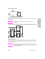
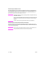
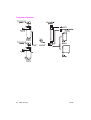
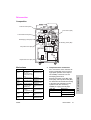
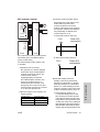
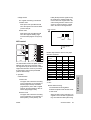
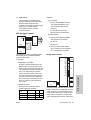
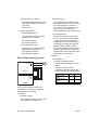
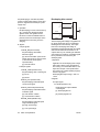
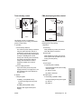
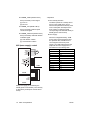
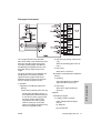
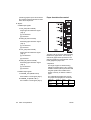
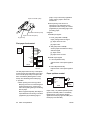
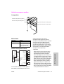
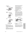
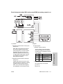
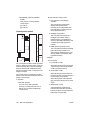
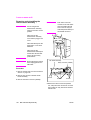
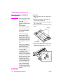
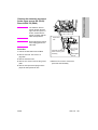
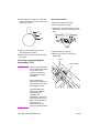
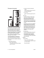
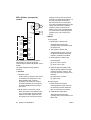
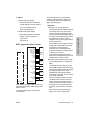
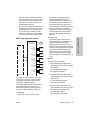
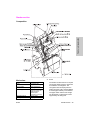
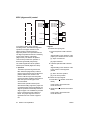
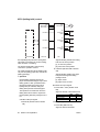
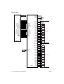
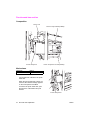
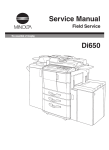
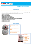
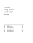
Overall protection circuit
CBR1
NF
CBR2
Protection by CBR1 and CBR2 (circuit breakers)
CBR1 and CBR2 interrupt the AC line instantaneously when an excessive current flows due to a
short in the AC line.
CAUTION
Safety
The CBR1 and CBR2 functions must not be deactivated under any
circumstances.
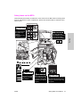
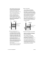
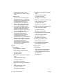
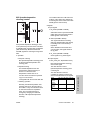
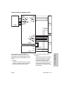
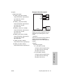
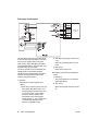
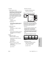
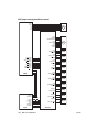
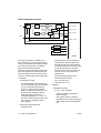
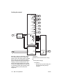
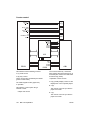
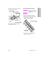
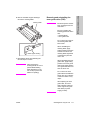
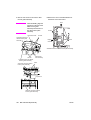
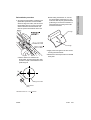
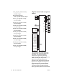
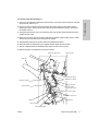
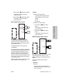
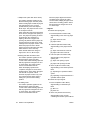
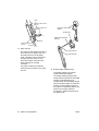
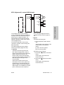
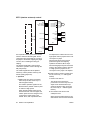
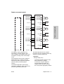
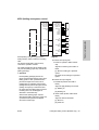
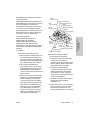
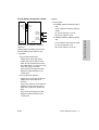
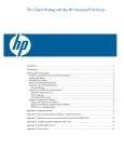
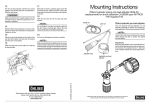
Protection by L2, L3 and L4 (fuser heater lamps) overheating prevention circuit
DCPS
TS2
TS1
RL1
PRCB
TH2
RL1
Control
section
L2
TH1
AC driver
section
L3
L4
Protection by software
The output voltage from TH1 (fuser temperature sensor 1) is read by the CPU. If this voltage is
abnormal, L2 (fuser heater lamp 1), L3 (fuser heater lamp 2), L4 (fuser heater lamp 3) and RL1
(main relay) are turned off.
CAUTION
ENWW
Do not change the gap between the roller and TH1. When replacing TH1, check
the specified mounting dimensions. The RL1 function must not be deactivated
under any circumstances.
Safety information
17
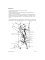
Protection by the hardware circuit
The output voltages from TH1 and TH2 (fuser temperature sensors) are compared with the
abnormality judgment reference value in the comparator circuit. If the output voltage from TH1
or TH2 exceeds the reference value, L2 (fuser heater lamp 1), L3 (fuser heater lamp 2), L4
(fuser heater lamp 3) and RL1 (main relay) are turned off.
CAUTION
Periodically check the TH2 face contacting the roller, and replace TH2 if any
abnormality is detected.
Since TH1 (fuser temperature sensor) face does not contact the roller, check
the distance from the roller and the sensor orientation if any abnormality is
detected.
The RL1 function must not be deactivated under any circumstances.
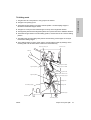
Protection by TS1 (thermostat/U) and TS2 (thermostat/L)
When the temperature of the fuser roller (upper/lower) exceeds the specified value, TSs are
turned off, thus interrupting the power to L2 (fuser heater lamp/1), L3 (fuser heater lamp/2), and
L4 (fuser heater lamp/3) directly.
CAUTION
18
Safety
Do not use any other electrical conductor in place of TS1 and TS2. Do not
change the distance between the roller and TS (thermostat).
ENWW
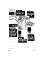
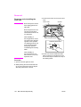
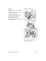
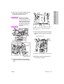
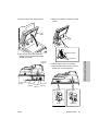
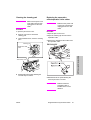
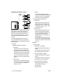
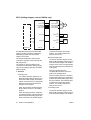
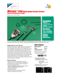
Safety labels on the MFPs
Caution labels shown below are attached in some areas on/in the MFP. When accessing these
areas for maintenance, repair, or adjustment, special care should be taken to avoid burns and
electric shock.
CAUTION
DO NOT INSERT
your finger into the
two RADF hinge
portions;
otherwise you may
be injured.
CAUTION
High temperature!
Do not touch. Use care
when clearing paper.
ATTENTION
Temp rature lev e!
Risque de br lure. Soyez
prudent en retirant la
feuille coinc e.
VORSICHT
Hei§e OberflŠche!
Brandverletzungsgefahr.
Bei Beseitigung von
Papierstaus vorsichtig
vorgehen.
PRECAUCION
ÁTemperatura alta!
No tocar. Tener cuidado al
remover el papel.
ATTENZIONE
Alta temperatura!
Non toccare. Agire con
prudenza nel rimuovere la
carta.
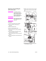
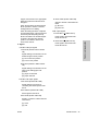
ENWW
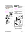
CAUTION
The fixing unit is
very hot. To avoide
getting burned, DO
NOT TOUCH.
CAUTION
ATTENTION
VORSICHT
PRECAUCION
ATTENZIONE
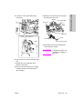
CAUTION
The conveyance fixing
unit is heavy. Use care
and draw it out gently;
otherwise you may be
injured.
CAUTION
ATTENTION
VORSICHT
PRECAUCION
ATTENZIONE
CAUTION
DO NOT put your hand between
the main body and developing
fixing unit; otherwise you may
be injured.
Safety labels on the MFPs
19
Safety
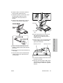
WARNING
This area generates
high voltage. If touched,
electrical shock may
occur. DO NOT TOUCH.
(Finisher with Cover
Sheet Feeder only)
(Punch Kit)
(Q3634A Finisher only)
(Q3634A Finisher)
CAUTION
You may be burned or injured if you touch any area that you are advised by
any caution label to avoid.
CAUTION
Do not remove caution labels. If any caution label has come off or is soiled and
therefore the caution cannot be read, contact our service office.
20
Safety
ENWW
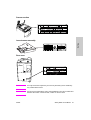
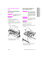
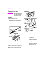
Scanner section
Safety
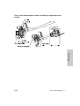
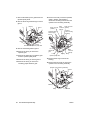
Laser/scanner assembly
Rear cover
CAUTION
You may be burned or injured if you touch any area that you are advised by
any caution label to avoid.
CAUTION
Do not remove caution labels. If any caution label has come off or is soiled and
therefore the caution cannot be read, contact our service office.
ENWW
Safety labels on the MFPs
21
WARNING
CAUTION
You may be burned or injured if you touch any area that you are advised by
any caution label to avoid.
CAUTION
Do not remove caution labels. If any caution label has come off or is soiled and
therefore the caution cannot be read, contact our service office.
22
Safety
ENWW
MFP overview
Overview of system . . . . . . . . . . . . . . . . . . . . . . . . . . . . . . . . . . . . . . . . . . . .
hp LaserJet 9055mfp/9065mfp product specifications . . . . . . . . . . . . . . . . . .
Type . . . . . . . . . . . . . . . . . . . . . . . . . . . . . . . . . . . . . . . . . . . . . . . . . . . .
Functions . . . . . . . . . . . . . . . . . . . . . . . . . . . . . . . . . . . . . . . . . . . . . . . .
Applicable copy paper . . . . . . . . . . . . . . . . . . . . . . . . . . . . . . . . . . . . . .
Options. . . . . . . . . . . . . . . . . . . . . . . . . . . . . . . . . . . . . . . . . . . . . . . . . .
Particulars of machine . . . . . . . . . . . . . . . . . . . . . . . . . . . . . . . . . . . . . .
Maintenance and life . . . . . . . . . . . . . . . . . . . . . . . . . . . . . . . . . . . . . . .
Environmental conditions . . . . . . . . . . . . . . . . . . . . . . . . . . . . . . . . . . . .
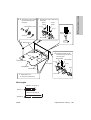
Central cross-sectional view . . . . . . . . . . . . . . . . . . . . . . . . . . . . . . . . . . . . .
Drive system diagram . . . . . . . . . . . . . . . . . . . . . . . . . . . . . . . . . . . . . . . . . .
Fuser/web drive section . . . . . . . . . . . . . . . . . . . . . . . . . . . . . . . . . . . . .
Drum drive section . . . . . . . . . . . . . . . . . . . . . . . . . . . . . . . . . . . . . . . . .
Developing drive section . . . . . . . . . . . . . . . . . . . . . . . . . . . . . . . . . . . .
Paper feed/vertical conveyance/tray up drive sections . . . . . . . . . . . . .
Tray 1 paper feed/automatic duplex unit (ADU) pre-registration
drive section . . . . . . . . . . . . . . . . . . . . . . . . . . . . . . . . . . . . . . . . . .
Charging and transfer/separation wire cleaning drive section . . . . . . . .
Automatic Duplex Unit (ADU) conveyance drive section . . . . . . . . . . . .
Paper exit drive section . . . . . . . . . . . . . . . . . . . . . . . . . . . . . . . . . . . . .
Toner supply drive section . . . . . . . . . . . . . . . . . . . . . . . . . . . . . . . . . . .
Optics drive section . . . . . . . . . . . . . . . . . . . . . . . . . . . . . . . . . . . . . . . .
ENWW
24
25
25
25
26
26
26
26
26
27
28
28
29
29
30
31
32
33
34
34
35
23
MFP overview
3
Overview of system
24
MFP overview
ENWW
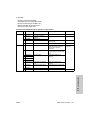
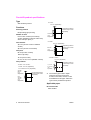
hp LaserJet 9055mfp/9065mfp product specifications
Type
Magnifications
Installation type
Fixed magnifications
Console type (floor-mounted)
• Metric area
x1.00, x2.00, x1.41, x1.22, x1.15, x0.86,
0.82, x0.71, x0.50
Copying method
Indirect electrostatic method
• Inch area
x1.00, x2.00, x1.55, x1.29, x1.21, x0.93,
0.77, x0.65, x0.50
Document tray type
Fixed
Special ratio magnifications
Photosensitive material
3 modes
OPC
Zoom magnifications
Sensitizing method
x0.25 to x4.00 (in 1 percent steps)
Laser writing
Vertical magnifications
Horizontal magnifications
Tray 1 tray for various paper sizes
(100 sheets of 80 g/m2 or 20 lb paper)
Warm-up time
g/m2
Q3637A (4000 sheets of 80
or 20 lb
paper) (optional)
Q3638A (4000 sheets of 80 g/m2 or 20 lb
paper) (optional)
5.5 minutes maximum
20° C, rated voltage
9055
6 minutes maximum
20° C, rated voltage
9065
First copy out time (FCOT)
Mode
A4/8.5 by 11
3.4 seconds or shorter (9055)
3.1 seconds or shorter (9065)
Applicable document types
* Straight paper ejection, platen mode, life
size, non AE or AES, without finisher, and
paper feed from Tray 2
Sheets, books, and solid objects
Document size
A3/11 by 17 maximum
Continuous copy speed (life size,
copies/min)
Copy paper size
●
x0.25 to x4.00 (in 1 percent steps)
Manual
Functions
●
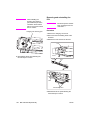
x0.25 to x4.00 (in 1 percent steps)
Three stacked trays (two for 500 sheets of
80 g/m2 or 20 lb paper, one for
1500 sheets of 80 g/m2 or 20 lb paper)
MFP overview
Paper feed trays
Metric area
A3 to A6R, F4
Inch area
11 by 17 to 8.5 by 5.5
Wide paper (up to 314 mm by 459 mm
maximum)
Size
cpm
A4/8.5 by 11
55 (9055)
65 (9065)
Continuous copy count
1 to 9999
Copy density selection
AE or AES, manual (9 steps)
Arbitrary density (2 modes)
ENWW
hp LaserJet 9055mfp/9065mfp product specifications
25
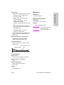
E-RDH memory capacity
Power consumption
Standard 64 MB
230 V Machine: 2300 W maximum (full
option)
Maximum 192 MB
120 V Machine: 1920 W maximum (full
option)
Applicable copy paper
Weight: Approximately 203 kg (447 lb)
Plain paper
2
High-quality paper of 60 g/m , or
17 lb to 90 g/m2, or 24 lb
External dimensions
Special paper (Tray 1 feed only)
OHT film
1140
Blueprint master paper
(both Tray 1 tray and stacked trays)
Tabs
Plain paper of 50 g/m2, or 13 lb to
59 g/m2, or 16 lb
Plain paper of 91 g/m2, or 24 lb to
200 g/m2, or 45 lb
766
650
(mm)
Options
HCI: Q3637A (Letter/A4), Q3638A
(Ledger/A3)
Paper exit Tray 100 sheet: Q3640A
Hard disk: Q3642A
Finisher: Q3633A, Q3634A
Cover sheet feeder: Post inserter Q3636A
Puncher: Punch Kit
• 2-hole Q3635A
• 3-hole Q3689A
• 4-hole Swedish Q3691A
• 4-hole Q3690A
Print Controller: Q3639A
Maintenance and life
Periodic maintenance: Every 250,000
copies
Machine life: 5,000,000 copies or 5 years
Environmental conditions
Temperature: 10° C to 30° C (50° F to
86° F)
Humidity: 10 percent to 80 percent RH
Note
The information herein may be
subject to change for
improvement without notice.
Particulars of machine
Power supply
230 VAC -14 percent to 10.6 percent
50Hz/60Hz
120 VAC ±10 percent 60 Hz
26
MFP overview
ENWW
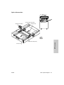
MFP overview
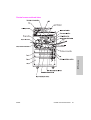
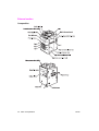
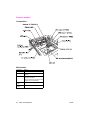
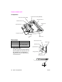
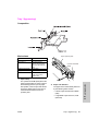
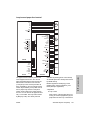
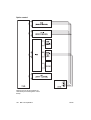
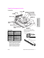
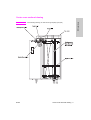
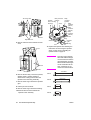
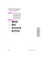
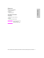
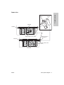
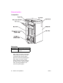
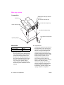
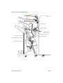
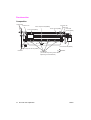
Central cross-sectional view
ENWW
Central cross-sectional view 27
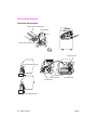
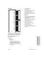
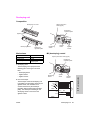
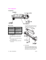
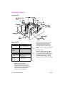
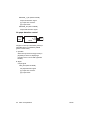
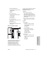
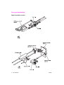
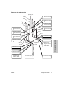
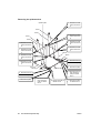
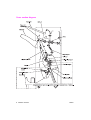
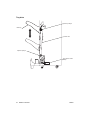
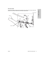
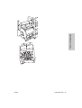
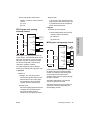
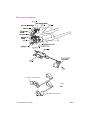
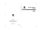
Drive system diagram
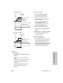
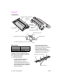
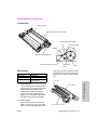
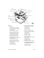
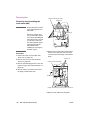
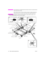
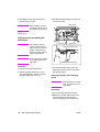
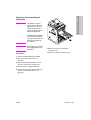
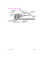
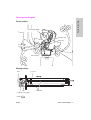
Fuser/web drive section
Cleaning web unwinding shaft
Web SD (SD2)
Ratchet
Cleaning web wind-up shaft
FRONT
Fixing input gear
Reverse/exit switching gate
Fixing upper roller
Fixing lower roller
Fixing motor (M4)
Decurler roller
Reverse gate SD (SD7)
28
MFP overview
ENWW
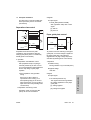
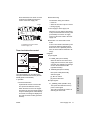
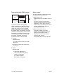
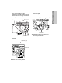
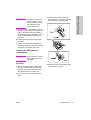
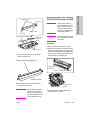
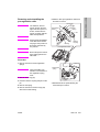
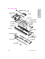
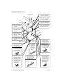
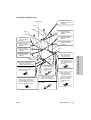
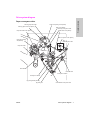
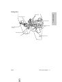
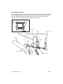
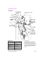
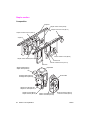
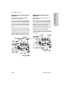
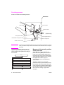
Drum drive section
Separation claw swing cam
Separation claw SD
(SD1)
Drum
Separation claw section
Drum motor (M2)
Drum motor (M2)
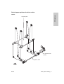
MFP overview
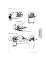
Toner conveyance screw
Toner guide roller
Toner conveyance screw
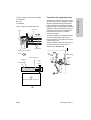
Developing drive section
Developing sleeve
Developing motor (M3)
Agitator screws
Agitator wheel
ENWW
Drive system diagram
29
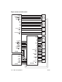
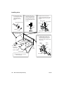
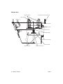
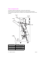
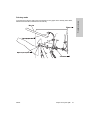
Paper feed/vertical conveyance/tray up drive sections
30
MFP overview
ENWW
MFP overview
Tray 1 paper feed/automatic duplex unit (ADU) pre-registration drive
section
ENWW
Drive system diagram
31
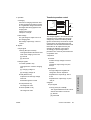
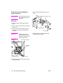
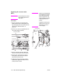
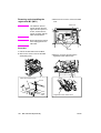
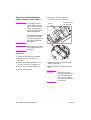
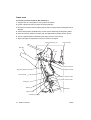
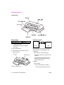
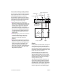
Charging and transfer/separation wire cleaning drive section
[Charging corona unit]
Charging cleaning motor (M14)
[Transfer and separation corona unit]
FRONT
Transfer/separation cleaning motor (M10)
32
MFP overview
ENWW
MFP overview
Automatic Duplex Unit (ADU) conveyance drive section
ENWW
Drive system diagram
33
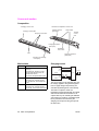
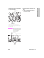
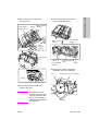
Paper exit drive section
Paper exit motor (M7)
Paper exit roller
Exit conveyance roller
Toner supply drive section
34
MFP overview
ENWW
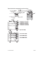
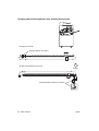
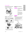
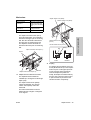
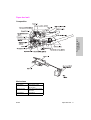
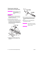
Optics drive section
Scanner drive wire (rear)
Scanner motor (M11)
Exposure unit
FRONT
MFP overview
Scanner drive wire (front)
V-mirror unit
ENWW
Drive system diagram
35
36
MFP overview
ENWW
MFP unit explanation
External section . . . . . . . . . . . . . . . . . . . . . . . . . . . . . . . . . . . . . . . . . . . . . . .
Composition . . . . . . . . . . . . . . . . . . . . . . . . . . . . . . . . . . . . . . . . . . . . . .
Drive section . . . . . . . . . . . . . . . . . . . . . . . . . . . . . . . . . . . . . . . . . . . . . . . . .
Composition . . . . . . . . . . . . . . . . . . . . . . . . . . . . . . . . . . . . . . . . . . . . . .
Mechanisms . . . . . . . . . . . . . . . . . . . . . . . . . . . . . . . . . . . . . . . . . . . . . .
M2 (drum) control. . . . . . . . . . . . . . . . . . . . . . . . . . . . . . . . . . . . . . . . . .
M4 (fuser) control . . . . . . . . . . . . . . . . . . . . . . . . . . . . . . . . . . . . . . . . . .
Scanner section . . . . . . . . . . . . . . . . . . . . . . . . . . . . . . . . . . . . . . . . . . . . . . .
Composition . . . . . . . . . . . . . . . . . . . . . . . . . . . . . . . . . . . . . . . . . . . . . .
Mechanisms . . . . . . . . . . . . . . . . . . . . . . . . . . . . . . . . . . . . . . . . . . . . . .
M11 (scanner) control . . . . . . . . . . . . . . . . . . . . . . . . . . . . . . . . . . . . . .
Exposure control . . . . . . . . . . . . . . . . . . . . . . . . . . . . . . . . . . . . . . . . . .
Original read control. . . . . . . . . . . . . . . . . . . . . . . . . . . . . . . . . . . . . . . .
APS control . . . . . . . . . . . . . . . . . . . . . . . . . . . . . . . . . . . . . . . . . . . . . .
AE control. . . . . . . . . . . . . . . . . . . . . . . . . . . . . . . . . . . . . . . . . . . . . . . .
Laser scanner unit . . . . . . . . . . . . . . . . . . . . . . . . . . . . . . . . . . . . . . . . . . . . .
Composition . . . . . . . . . . . . . . . . . . . . . . . . . . . . . . . . . . . . . . . . . . . . . .
Mechanisms . . . . . . . . . . . . . . . . . . . . . . . . . . . . . . . . . . . . . . . . . . . . . .
M15 (polygon) control . . . . . . . . . . . . . . . . . . . . . . . . . . . . . . . . . . . . . .
Image write control. . . . . . . . . . . . . . . . . . . . . . . . . . . . . . . . . . . . . . . . .
Drum unit . . . . . . . . . . . . . . . . . . . . . . . . . . . . . . . . . . . . . . . . . . . . . . . . . . . .
Composition . . . . . . . . . . . . . . . . . . . . . . . . . . . . . . . . . . . . . . . . . . . . . .
Mechanisms . . . . . . . . . . . . . . . . . . . . . . . . . . . . . . . . . . . . . . . . . . . . . .
Separation claw control . . . . . . . . . . . . . . . . . . . . . . . . . . . . . . . . . . . . .
Paper guide plate control . . . . . . . . . . . . . . . . . . . . . . . . . . . . . . . . . . . .
Corona unit section . . . . . . . . . . . . . . . . . . . . . . . . . . . . . . . . . . . . . . . . . . . .
Composition . . . . . . . . . . . . . . . . . . . . . . . . . . . . . . . . . . . . . . . . . . . . . .
Mechanisms . . . . . . . . . . . . . . . . . . . . . . . . . . . . . . . . . . . . . . . . . . . . . .
Charging control. . . . . . . . . . . . . . . . . . . . . . . . . . . . . . . . . . . . . . . . . . .
Transfer/separation control . . . . . . . . . . . . . . . . . . . . . . . . . . . . . . . . . .
M14 (charger cleaning) control . . . . . . . . . . . . . . . . . . . . . . . . . . . . . . .
M10 (transfer/separation cleaning) control. . . . . . . . . . . . . . . . . . . . . . .
PCL/TSL control. . . . . . . . . . . . . . . . . . . . . . . . . . . . . . . . . . . . . . . . . . .
ENWW
40
40
41
41
41
42
42
44
44
44
45
48
48
49
51
52
52
52
53
53
56
56
56
57
57
58
58
58
58
59
60
61
62
37
MFP unit explanation
4
Developing unit . . . . . . . . . . . . . . . . . . . . . . . . . . . . . . . . . . . . . . . . . . . . . . . 63
Composition . . . . . . . . . . . . . . . . . . . . . . . . . . . . . . . . . . . . . . . . . . . . . . 63
Mechanisms . . . . . . . . . . . . . . . . . . . . . . . . . . . . . . . . . . . . . . . . . . . . . . 63
M3 (developing) control . . . . . . . . . . . . . . . . . . . . . . . . . . . . . . . . . . . . . 63
Developing bias control . . . . . . . . . . . . . . . . . . . . . . . . . . . . . . . . . . . . . 64
Dmax (maximum contrast) control . . . . . . . . . . . . . . . . . . . . . . . . . . . . . 65
Gradation correction control. . . . . . . . . . . . . . . . . . . . . . . . . . . . . . . . . . 67
Dot diameter correction control . . . . . . . . . . . . . . . . . . . . . . . . . . . . . . . 68
Toner density control . . . . . . . . . . . . . . . . . . . . . . . . . . . . . . . . . . . . . . . 69
FM4 (developing suction) control . . . . . . . . . . . . . . . . . . . . . . . . . . . . . . 69
Toner supply unit . . . . . . . . . . . . . . . . . . . . . . . . . . . . . . . . . . . . . . . . . . . . . . 70
Composition . . . . . . . . . . . . . . . . . . . . . . . . . . . . . . . . . . . . . . . . . . . . . . 70
Mechanisms . . . . . . . . . . . . . . . . . . . . . . . . . . . . . . . . . . . . . . . . . . . . . . 70
Toner level detection control . . . . . . . . . . . . . . . . . . . . . . . . . . . . . . . . . 71
M12 (toner supply) control . . . . . . . . . . . . . . . . . . . . . . . . . . . . . . . . . . . 72
Cleaning/toner recycle unit. . . . . . . . . . . . . . . . . . . . . . . . . . . . . . . . . . . . . . . 73
Composition . . . . . . . . . . . . . . . . . . . . . . . . . . . . . . . . . . . . . . . . . . . . . . 73
Mechanisms . . . . . . . . . . . . . . . . . . . . . . . . . . . . . . . . . . . . . . . . . . . . . . 73
Toner guide roller (TGR) control . . . . . . . . . . . . . . . . . . . . . . . . . . . . . . 74
Other control . . . . . . . . . . . . . . . . . . . . . . . . . . . . . . . . . . . . . . . . . . . . . 74
Tray 2/3 paper feed unit . . . . . . . . . . . . . . . . . . . . . . . . . . . . . . . . . . . . . . . . . 75
Composition . . . . . . . . . . . . . . . . . . . . . . . . . . . . . . . . . . . . . . . . . . . . . . 75
Mechanisms . . . . . . . . . . . . . . . . . . . . . . . . . . . . . . . . . . . . . . . . . . . . . . 75
First paper feed control . . . . . . . . . . . . . . . . . . . . . . . . . . . . . . . . . . . . . 77
Paper up drive control . . . . . . . . . . . . . . . . . . . . . . . . . . . . . . . . . . . . . . 79
Paper size detection control. . . . . . . . . . . . . . . . . . . . . . . . . . . . . . . . . . 80
No paper detection control . . . . . . . . . . . . . . . . . . . . . . . . . . . . . . . . . . . 81
Tray 4 paper feed unit . . . . . . . . . . . . . . . . . . . . . . . . . . . . . . . . . . . . . . . . . . 82
Composition . . . . . . . . . . . . . . . . . . . . . . . . . . . . . . . . . . . . . . . . . . . . . . 82
Mechanisms . . . . . . . . . . . . . . . . . . . . . . . . . . . . . . . . . . . . . . . . . . . . . . 82
First paper feed control . . . . . . . . . . . . . . . . . . . . . . . . . . . . . . . . . . . . . 84
Paper up drive control . . . . . . . . . . . . . . . . . . . . . . . . . . . . . . . . . . . . . . 86
Paper size detection control. . . . . . . . . . . . . . . . . . . . . . . . . . . . . . . . . . 87
No paper detection control . . . . . . . . . . . . . . . . . . . . . . . . . . . . . . . . . . . 87
Tray 1 (bypass tray) . . . . . . . . . . . . . . . . . . . . . . . . . . . . . . . . . . . . . . . . . . . . 89
Composition . . . . . . . . . . . . . . . . . . . . . . . . . . . . . . . . . . . . . . . . . . . . . . 89
Mechanisms . . . . . . . . . . . . . . . . . . . . . . . . . . . . . . . . . . . . . . . . . . . . . . 89
First paper feed control . . . . . . . . . . . . . . . . . . . . . . . . . . . . . . . . . . . . . 90
Paper up/down control . . . . . . . . . . . . . . . . . . . . . . . . . . . . . . . . . . . . . . 90
Paper size detection control. . . . . . . . . . . . . . . . . . . . . . . . . . . . . . . . . . 91
No paper detection control . . . . . . . . . . . . . . . . . . . . . . . . . . . . . . . . . . . 92
Vertical conveyance section. . . . . . . . . . . . . . . . . . . . . . . . . . . . . . . . . . . . . . 93
Composition . . . . . . . . . . . . . . . . . . . . . . . . . . . . . . . . . . . . . . . . . . . . . . 93
Mechanisms . . . . . . . . . . . . . . . . . . . . . . . . . . . . . . . . . . . . . . . . . . . . . . 93
Vertical conveyance control . . . . . . . . . . . . . . . . . . . . . . . . . . . . . . . . . . 93
Automatic duplex unit (ADU) . . . . . . . . . . . . . . . . . . . . . . . . . . . . . . . . . . . . . 95
Composition . . . . . . . . . . . . . . . . . . . . . . . . . . . . . . . . . . . . . . . . . . . . . . 95
Mechanisms . . . . . . . . . . . . . . . . . . . . . . . . . . . . . . . . . . . . . . . . . . . . . . 96
Loop/second paper feed control. . . . . . . . . . . . . . . . . . . . . . . . . . . . . . 101
Paper conveyance control . . . . . . . . . . . . . . . . . . . . . . . . . . . . . . . . . . 103
Paper reverse and exit control . . . . . . . . . . . . . . . . . . . . . . . . . . . . . . . 104
ADF paper conveyance/feed control . . . . . . . . . . . . . . . . . . . . . . . . . . 108
38
ENWW
111
111
111
113
114
116
116
117
118
122
124
126
MFP unit explanation
Fuser unit . . . . . . . . . . . . . . . . . . . . . . . . . . . . . . . . . . . . . . . . . . . . . . . . . . .
Composition . . . . . . . . . . . . . . . . . . . . . . . . . . . . . . . . . . . . . . . . . . . . .
Mechanisms . . . . . . . . . . . . . . . . . . . . . . . . . . . . . . . . . . . . . . . . . . . . .
M16 (web drive) control . . . . . . . . . . . . . . . . . . . . . . . . . . . . . . . . . . . .
Fuser temperature control . . . . . . . . . . . . . . . . . . . . . . . . . . . . . . . . . .
Other kinds of control . . . . . . . . . . . . . . . . . . . . . . . . . . . . . . . . . . . . . . . . . .
Parts energized when SW1 (main power) is off . . . . . . . . . . . . . . . . . .
Parts that operate when SW1 (main power)/SW2 (secondary
power) is on . . . . . . . . . . . . . . . . . . . . . . . . . . . . . . . . . . . . . . . . .
Cooling fan control . . . . . . . . . . . . . . . . . . . . . . . . . . . . . . . . . . . . . . . .
Control panel control . . . . . . . . . . . . . . . . . . . . . . . . . . . . . . . . . . . . . .
Counter control. . . . . . . . . . . . . . . . . . . . . . . . . . . . . . . . . . . . . . . . . . .
Option control. . . . . . . . . . . . . . . . . . . . . . . . . . . . . . . . . . . . . . . . . . . .
ENWW
39
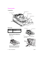
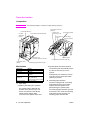
External section
Composition
40
MFP unit explanation
ENWW
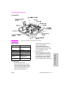
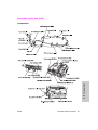
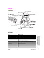
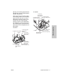
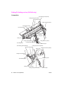
Drive section
Composition
Scanner motor (M11)
Drum motor (M2)
Toner bottle motor (M13)
Developing motor (M3)
Fixing motor (M4)
Loop roller motor (M6)
Paper feed motor (M1)
*1
Mechanism
Driven parts
Drum
drive*1
Drum, Toner guide
Gear drive
roller, Toner
(dedicated motor)
conveyance screw,
and Separation claw
swing
Developing
drive*1
Developing sleeve
Gear drive
(dedicated motor)
Fuser
drive*1
Fuser roller (upper)
Gear drive
(dedicated motor)
Paper feed
drive*1
Tray 2/3/4, Vertical
conveyance roller
(middle/lower)
Gear drive
(dedicated motor) +
Belt
Tray 1/loop
drive*1
Tray 1 feed roller
Gear drive
and ADU
(dedicated motor) +
pre-registration roller Belt
Scanner
drive*1
Exposure unit,
V-mirror unit
Wire drive
(dedicated motor)+
Belt
Paper exit
drive*1
Paper exit roller
Gear drive
(dedicated motor)
ENWW
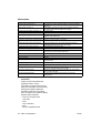
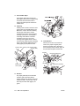
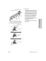
Method
Independent drive mechanisms
Drive mechanisms of this machine are
driven by dedicated motors to ensure
high-speed operation and to improve
serviceability of the drum unit and
developing performance.
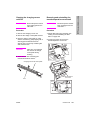
Speeds of the drum motor (M2), fuser
motor (M4), and loop roller motor (M6)
are switched as shown below according
to the paper type selected in the key
operator mode, thus enhancing
reliability of copying on thick paper.
Paper type
Motor speed
Thick paper
185 mm/s
Others
280 mm/s (9055)
320 mm/s (9065)
Drive section
41
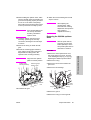
MFP unit explanation
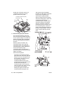
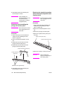
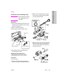
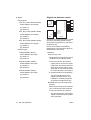
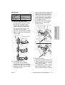
Mechanisms
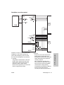
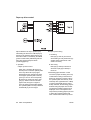
M2 (drum) control
b Output signals
1 DRUM_CONT (PRCB to M2)
M2 (drum) ON/OFF control signal
[L]: M2 on
[H]: M2 off
5V
P.GND
DRUM CONT
DRUM CLK
CW/CCW
DRUM EM
PRCB
M2
24V2
MS1
MS2
P.GND
DCPS
M2 (drum) is controlled by PRCB (printer
control board) and the motor drive power is
supplied from DCPS (DC power supply unit).
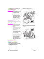
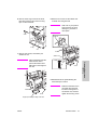
1 Operation
M2 (drum) is a motor driven by 24 VDC. It
drives the drum, toner guide roller, toner
conveyance screw, and separation claw
swing. The flywheel mechanism adopted
for M2 ensures accurate and steady
rotation.
M2 starts rotating when the START button
is pressed and stops when the specified
time lapses after completion of second
paper feeding of the last copy.
When either one of the front-left and
front-right doors of this machine opens,
MS1 (interlock MS/R) or MS2 (interlock
MS/L) actuates to stop supplying the DC
power to the motor, causing M2 to stop.
2 Signals
a Input signal
1 DRUM_EM (M2 to PRCB)
M2 (drum) rotation abnormality
detection signal
[H]: Rotation error (when motor speed
changes by 6.5 percent more or less
than the motor speed specified value)
[L]: Normal rotation
42
MFP unit explanation
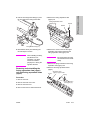
2 CW/CCW (PRCB to M4)
M2 (drum) rotational direction
switchover signal
[L]: CW rotation
[H]: CCW rotation
3 DRUM_CLK (PRCB to M2)
M2 (drum) rotational speed control
clock signal
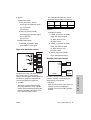
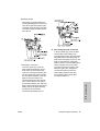
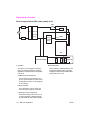
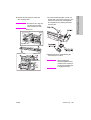
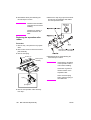
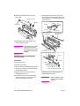
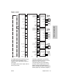
M4 (fuser) control
5V
P.GND
MAINM CONT
MAINM CLK
MAINM F/R
MAINM EM
PRCB
M4
24V2
MS1
MS2
P.GND
DCPS
M4 (fuser) is controlled by PRCB (printer
control board) and the motor drive power is
supplied from DCPS (DC power supply unit).
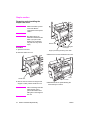
1 Operation
M4 (fuser) is a motor driven by 24 VDC. It
drives the fuser roller.
M4 starts rotating when the START button
is pressed and stops when the last copied
paper has been ejected.
During the warm-up operation, M4 rotates
to rotate the fuser roller.
ENWW
2 Signals
a Input signal
1 MAINM_EM (M4 to PRCB)
M4 (fuser) rotation error detection
signal
[H]: Rotation error (when motor speed
changes by 6.5 percent more or less
than the motor speed specified value)
[L]: Normal rotation
b Output signals
1 MAINM_CONT (PRCB to M4)
M4 (fuser) ON/OFF control signal
[L]: M4 on
[H]: M4 off
2 MAINM_F/R (PRCB to M4)
M4 (fuser) rotational direction
switchover signal
[L]: CW rotation
[H]: CCW rotation
MFP unit explanation
3 MAINM_EM (M4 to PRCB)
M4 (fuser) rotational speed control
clock signal
ENWW
Drive section
43
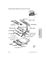
Scanner section
Composition
Mechanisms
Mechanism
Method
Light source
Xenon lamp
Exposure
Light source moving slit exposure, static
exposure
Scanning
Platen original scanning: 1st, 2nd, and
3rd mirrors are shifted.
ADF original scanning: Original is moved
with light source held stationary.
Lamp power
supply
Lamp cord
Scanner
cooling
Cooling fan
44
MFP unit explanation
ENWW
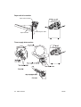
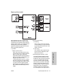
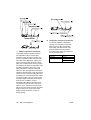
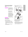
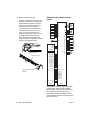
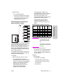
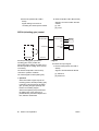
M11 (scanner) control
SCAN CLK
SCAN FR
SCAN MGN
SCAN CUR1
SCAN CUR2
SCAN CUR3
MODE1
MODE2
MODE3
SCANHP PS
c Exposure unit home position search
U
V
W
S.GND
SIG
5V
M11
PS61
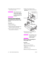
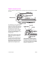
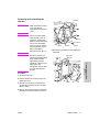
When SW2 (sub power switch) or the
START button is pressed, M11
(scanner) searches for the home
position of the exposure unit. However,
this operation is performed in different
ways depending on whether PS61
(scanner HP) is on or off.
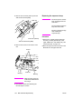
1 When PS61 (scanner HP) is off
PRCB
PS61
5V2
S.GND
Platen APS
read position
24V1
5V2
S.GND
P.GND
DCPS
SCDB
M11 (scanner) is driven by SCDB (scanner
drive board) and is controlled by PRCB
(printer control board).
The related signal is PS61 (scanner HP).
1 Operation
2 When PS61 (scanner HP) is on
PS61
Platen APS
read position
a Operation of M11 (scanner)
The rotational speed, direction, and
amount of movement of M11 is
determined by the increment of the
driving step count. This count is reset
each time PS61 (scanner HP) is turned
on or off by the exposure unit.
b Movement speed of the exposure unit
Scanning speed
Operation mode
Movement speed
Scan
320 mm/s (1:1)
Return
640 mm/s
Home position search
247 mm/s
ENWW
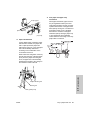
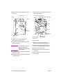
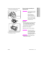
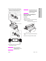
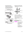
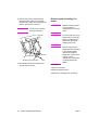
d Read with shading correction
Shading correction is performed in
different ways depending on whether
SW2 (sub power) is on or the START
button is on. When shading correction
starts, the exposure unit is at the home
position and PS61 (scanner HP) is off.
1 When SW2 (sub power) is on
L1 (exposure lamp) turns on. Next,
M11 (scanner) moves the exposure
unit toward the paper exit side. After
being driven by the specified number
of steps, M11 stops, thus reading the
light reflected by the white reference
plate installed underneath the glass
stopper plate and performing the first
Scanner section
45
MFP unit explanation
M11 (scanner) is a 3-phase stepping
motor driven by the 3-phase bipolar
constant-current drive method. The
motor is turned on/off by
supplying/stopping clock pulses.
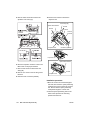
white correction. Next, M11 moves
the exposure unit toward the paper
exit side. After being driven by the
specified number of steps, M11
performs the second white correction.
Then, L1 is turned off for black
correction, searching for the home
position of the exposure unit.
In each of the first and second
shading correction processes, the
CCD 1 line data is read to compare
brightness levels between pixels. The
brighter data is used as white
correction data.
PS61
Platen APS
read position
First white correction
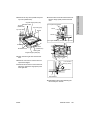
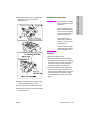
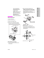
e ADF copy operation
After completion of the shading
correction started by pressing the
START button, M11 (scanner) moves
the exposure unit toward the paper exit
side. After being driven by the specified
number of steps from the position where
PS61 (scanner HP) was turned on, it
stops. This position is the exposure
position for ADF copy operation.
Then, ADF copy operation is performed.
After completion of the ADF copy
operation, L1 (exposure lamp) is turned
off to start searching for the exposure
unit home position.
PS61
Platen APS
read position
Second
white correction
Black correction
Home position search
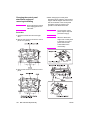
First white correction
Second
white correction
Home position search
Original read position
2 When the START button is on
L1 (exposure lamp) turns on. Next,
M11 (scanner) moves the exposure
unit toward the paper exit side. After
being driven by the specified number
of steps, M11 (scanner) stops, thus
reading the light reflected by the white
reference plate installed underneath
the glass stopper plate and
performing the first white correction.
Next, M11 moves the exposure unit
toward the paper exit side. After being
driven by the specified number of
steps, M11 performs the second
white correction.
Then, M11 proceeds to the ADF copy
operation or platen copy operation.
46
MFP unit explanation
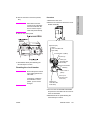
f Platen (scanner glass) copy operation
Platen copy operation is performed in
different ways depending on whether
AE control is performed.
After completion of the shading
correction started by pressing the
START button, AE scanning is
performed in the paper feed direction if
the AE mode has been selected.
Then, exposure scanning is performed
at the speed corresponding to the
specified magnification by the distance
corresponding to the original size, thus
searching for the home position.
ENWW
b PRCB output signal
1 Operation with AE
PS61
Platen APS
read position
First white correction
Second
white correction
AE scanning
Exposure scanning
1 SCAN_CLK (PRCB to SCDB)
M11 (scanner) clock signal
2 SCAN_F/R (PRCB to SCDB)
M11 (scanner) rotational direction
switchover signal
[L]: The exposure unit is moved
toward the paper exit side.
[H]: The exposure unit is moved
toward the paper feed side.
3 MODE1 to 3 (PRCB to SCDB)
Home position search
2 Operation without AE
PS61
Platen APS
read position
M11 (scanner) energize switchover
signals
4 SCAN_CUR1 to 3 (PRCB to SCDB)
M11 (scanner) energize current
switchover signals
c SCDB output signals
1 U, V, W (SCDB to M11)
First white correction
Second
white correction
Exposure scanning
M11 (scanner) drive control signals
These signals are used to control
rotation of M11 (scanner). By
supplying and stopping clock pulses,
the motor is turned on/off and the
rotational direction is switched.
Home position search
2 Signals
MFP unit explanation
a Input signals
1 SIG/SCANHP_PS (PS61 to SCDB to
PRCB)
Scanner home position detection
signal
The reference position of the home
position of the exposure unit is
detected.
[L]: The exposure unit is detected.
[H]: The exposure unit is not
detected.
ENWW
Scanner section
47
Exposure control
Original read control
EXP CONT
L1
24V
CONT
LAMP.PG
L1 INVB
PRCB
5V2
S.GND
24V1
5V2
S.GND
P.GND
L.PG
DCPS
SCDB
L1 (exposure lamp) is driven by L1 INVB (L1
inverter) and is controlled by PRCB (printer
control board) via SCDB (scanner drive
board).
1 Operation
L1 (exposure lamp) is a xenon lamp driven
by the inverter circuit. The xenon lamp can
emit a constant light intensity and
generates less heat than other lamps, so it
does not require the light intensity control
circuit that has been used in the existing
machines, requiring no thermal protector
circuit. However, since L1 is held lit when
the exposure unit is stationary in the ADF
mode, FM9 (scanner cooling) is installed
in the read section.
2 Signals
a Output signals
1 EXP_CONT (PRCB to SCDB)
L1 (exposure lamp) ON/OFF control
signal
[L]: L1 on
[H]: L1 off
2 CONT (SCDB to L1 INVB)
ICB
12V2
12V2
GND
APR
ADRST
PDWN
GND
TCK
/TCK
GND
RCK
/RCK
GND
LCLK1
/LCLK1
GND
SCLK
/SEN
SDI
SDO
TG
CLAMP
GND
BCLAMP
GND
D0
/D0
GND
D1
/D1
GND
D2
/D2
GND
LCLK0
/LCLK0
GND
5V2
5V2
GND
CCD
ADB
Original read control is performed by ADB
(A/D converter board) and CCD sensor
installed in ADB.
1 Operation
The light reflected by the exposed original
is input to the CCD sensor through the
lens. The analog voltage corresponding to
the quantity of the input light is
A/D-converted in the ADB (A/D converter
board), being output to the ICB (image
control board).
L1 (exposure lamp) ON/OFF control
signal
[L]: L1 on
[H]: L1 off
48
MFP unit explanation
ENWW
a Original read
PS65 (APS/3) and the signal read by
the CCD sensor. PS63 to PS65 are
used to detect the original size in the
sub-scanning direction and the CCD
sensor is used to detect the original
size in the main scanning direction.
The original read timing is as follows:
1 Platen mode
After lapse of the specified interval
since the exposure unit turned PS61
(scanner HP) off.
2 ADF mode
Paper exit side
After lapse of the specified interval
since the original's leading edge
turned PS306 (original conveyance)
on.
PS65
PS63
PS64
APS control
ICB
APS TIMING
SIZE PS L
SIZE PS S
SIZE ANA
PRCB
24V1
5V2
S.GND
P.GND
DCPS
S.GND
APS TIM
5V
S.GND
APS.1
APS 5V
S.GND
APS.2
APS 5V
S.GND
APS.3
APS 5V
S.GND
SIZE PS L
5V
PS51
PS64
PS65
PS309
S.GND
SIZE PS S
5V
PS310
A.GND
SIZE ANA
3.3V
VR301
SCDB
The APS method used in the platen mode is
different from that used in the ADF mode.
The signal read by the APS sensor or ADF's
original size detection sensor is processed
by ICB (image control board) via SCDB
(scanner drive board).
1 Operation
a APS detection
1 ADF mode
The paper size is detected according
to the combination of on/off states of
PS309 (original size/2) and PS310
(original size/1) of the ADF's original
feed tray and the resistance value of
VR301 (original paper size).
2 Platen mode
The paper size is detected according
to the combination of on/off states of
PS63 (APS/1), PS64 (APS/2), and
ENWW
Photo sensor
LED
PS63
Relationships between sensors and paper
sizes are as follows:
Sensor
PS65
PS63
PS64
Paper size
Min. size
{
{
{
B5R
z
{
{
B5
{
{
{
B4
z
z
z
A4R
z
z
{
A4
{
{
{
A3
z
z
z
8.5 by 11R
z
{
{
8.5 by 11
{
{
{
8.5 by 14
z
z
z
11x 17
z
z
z
z ON
{ OFF
b APS detection timing
The APS detection timing differs
between the platen mode and DF mode.
1 ADF mode
When the ADF mode is selected or an
original is set on the ADF original feed
tray, APS detection takes place using
Scanner section
49
MFP unit explanation
APC CONT
COVER SIG
APS.1 SIG
APS.2 SIG
APS.3 SIG
PS309 (original size/2), PS310
(original size/1), and VR301 (original
size).
2 Platen mode
When the ADF is closed and PS51
(APS timing) turns on, L1 (exposure
lamp) turns on and the CCD detects
the reflected light to detect the
original size in the main scanning
direction. Since ADF is still open at
this time, the black level of the sky
shot (outside the original) and the
white level of the original (inside the
original) are detected according to
whether an original is present. At this
time, the original size in the
sub-scanning direction is detected
using PS63 to PS65 (APS/1 to
APS/3). When the ADF is closed
completely and PS311 (ADF
open/close) turns on, CCD reads the
white level of the platen cover and the
black level in the original. Among the
two original sizes detected as
discussed above, the larger size is
determined as the original size in the
main scanning direction.
2 Signals
a Input signals
1 APS_TIM (PS51 to SCDB)
ADF open/close detection signal
[L]: ADF is closed.
[H]: ADF is open.
2 APS.1/APS.1_SIG (PS63 to SCDB to
ICB)
4 APS3/APS.3_SIG (PS65 to SCDB to
ICB)
Paper size detection signal
[L]: Paper is detected.
[H]: Paper is not detected.
5 SIZE_PS_L (PS309 to SCDB to ICB)
Paper size detection signal
[L]: Paper is detected.
[H]: Paper is not detected.
6 SIZE_PS_S (PS310 to SCDB to ICB)
Paper size detection signal
[L]: Paper is detected.
[H]: Paper is not detected.
7 SIZE_ANA (PS301 to SCDB to ICB)
Paper size detection signal
[L]: Paper is detected.
[H]: Paper is not detected.
8 COVER_SIG (SCDB to ICB)
Same as APS TIM signal.
9 APS_TIMING (SCDB to PRCB)
Same as APS TIM signal.
b Output signals
1 APS_CONT
This signal controls on/off states of
APS_5V power for driving PS63,
PS64, and PS65 (APS1 to APS3).
[L]: APS_5V off
[H]: APS_5V on
Paper size detection signal
[L]: Paper is detected.
[H]: Paper is not detected.
3 APS.2/APS.2_SIG (PS64 to SCDB to
ICB)
Paper size detection signal
[L]: Paper is detected.
[H]: Paper is not detected.
50
MFP unit explanation
ENWW
AE control
ICB
<AE sampling area>
12V2
12V2
GND
APR
ADRST
PDWN
GND
TCK
/TCK
GND
RCK
/RCK
GND
LCLK1
/LCLK1
GND
SCLK
/SEN
SDI
SDO
TG
CLAMP
GND
BCLAMP
GND
D0
/D0
GND
D1
/D1
GND
D2
/D2
GND
LCLK0
/LCLK0
GND
5V2
5V2
GND
1) Normal copy
10 mm inside the perimeter of the
original detected by APS.
2) Non-image area erasure mode
Entire original area detected during
pre-scanning.
2 ADF mode
The image at the leading edge of the
original is read when the PRINT
button is pressed.
CCD
ADB
The read data is used to measure the
image density on the original.
<AE sampling area>
1) Main scanning direction
10-mm area inside the original
detected by APS
2) Sub-scanning direction
2-to-4 mm area from the leading edge
of the original.
The CCD sensor detects the image density
on an original during AE scanning to select
the optimum copy gamma correction curve.
MFP unit explanation
AE processing is controlled by the ICB
(image control board).
1 Operation
a AE detection
1 Platen mode
The image density on an original is
measured during AE scanning
preceding the exposure scanning that
is carried out after depression of the
START button.
ENWW
Scanner section
51
Laser scanner unit
Composition
Index sensor board (INDXSB)
Laser driver board (LDB)
Cylindrical lens 2
Collimator lens unit
Write mirror
Cylindrical lens 1
Polygon mirror
Index mirror
f lens
Mechanisms
Mechanism
Method
Scan*1
Polygon mirror
Light source*2
1-chip, 2-beam laser diode
Semiconductor laser
Write mirror
Collimator lens
(Power: 15 mW per beam)
Reference positioning Index sensor
*1
Path of laser light
The light output from the semiconductor
laser is radiated onto the OPC drum via
the collimator lens, cylindrical lens 1,
polygon mirror, fθ lens, cylindrical lens
2, and write mirror.
52
MFP unit explanation
Cylindrical lens 1
Polygon mirror
f lens
Cylindrical lens 2
ENWW
Light source
2 Signals
Conventionally, two parallel beams
were generated from two laser beams.
The laser diode adopted for this
machine can generate two beams using
a single chip, requiring neither
fine-adjustment prism nor beam
composition prism.
a Input signals
1 POLM_LOCK (PMDB to PRCB)
This signal indicates the clock
synchronization state of M15
(polygon).
[L]: Synchronous (normal)
[H]: Asynchronous (abnormal)
M15 (polygon) control
b Output signals
24V1
P.GND
POLM CONT
POLM CLK
POLM LOCK
1 POLM_CONT (PRCB to PMDB)
M15
This signal turns on/off M15.
[L]: M15 on
PMDB
[H]: M15 off
PRCB
2 POLM_CLK (PRCB to PMDB)
24V/1
5V/2
S.GND
P.GND
This is a reference clock signal for
PLL-controlling M15 in PMDB.
DCPS
M15 (polygon) is driven by PMDB (polygon
drive board) and is controlled by PRCB
(printer control board).
Image write control
5V
SGND
/IND
SGND
/INDPR
1 Operation
GND
VIDEO2
/VIDEO2
GND
LPR5V
LD5V
LD5V
GND
VIDEO1
/VIDEO1
GND
/ENB1
/S/H1
/ALM1
GND
/ENB2
/S/H2
/ALM2
GND
DADI
DACLK
DALD
a Explanation of operation
M15 is a 3-phase brushless DC motor
which is driven by the 3-phase bipolar
method. The current flowing through the
coil is switched according to the position
of the rotor detected by the position
sensor (magnetic sensor) in the motor.
This motor rotates the polygon mirror to
scan the laser beams from LDB (laser
driver board) in the axial direction of the
drum. Its rotation is held constant by
PLL control.
b Rotational speed
DCPS
M15 is powered by 24 VDC and its
rotational speed is as follows:
Rotational
speed
Linear speed
9055
9065
37,795 rpm
320 mm/s
-
normal
33,070 rpm
280 mm/s
normal -
21,850 rpm
185 mm/s
thick paper
ENWW
24V1
5V2
S.GND
P.GND
INDXSB
LDB
CCD
ADB
ICB
The analog image data from the CCD sensor
is A/D-converted by the ADB (A/D converter
board), then sent to the ICB (image control
board) for data processing. The processed
image data is converted into a laser beam
on the LDB (laser driver board), and then the
Laser scanner unit
53
MFP unit explanation
*2
beams are radiated onto the drum surface.
Two beams are emitted per laser diode. Two
lines of image data is written per scan.
The write start reference position is detected
by the index sensor board. The ICB has an
E-RDH function to store digitized image
data. Various editing functions can be
performed based on this data.
1 Operation
a Image processing
The following processing is performed
by the ICB (image control board):
1 Automatic offset control (AOCl)
The IC on the A/D converter board
(ADB) automatically adjusts the
analog offset voltage of the CCD
sensor output so that it is at the lower
limit of the A/D converter level.
2 Automatic gain control (AGC)
During shading correction, the white
reference plate is read to adjust the
analog amplification factor of the CCD
sensor output so that the read level is
at the upper limit of the A/D converter
level.
3 Shading correction
<Timing>
• When SW2 (sub power) is on
• At job start
4 Brightness/density conversion
5 AE processing
6 Text/dot pattern judgment
7 Filtering
8 Magnification change processing
9 Copy gamma correction
10 Skew correction
11 Error diffusion processing
12 Data compression/expansion
processing
b Write
The image control board (ICB) sends
image data on a pixel basis to laser
driver board (LDB) according to the
control signals from the PRCB (printer
control board).
LDB causes the laser light to be emitted
for a period corresponding to the image
data. This laser light is radiated onto the
drum surface.
1 Maximum power control (MPC)
Image control board (ICB) informs
LDB (laser driver board) of the
maximum output value and sets that
value for the laser beam emission.
LDB store this value and maintain the
laser beam level using the APC (Auto
Power Control).
<MPC timing>
When SW2 (sub power switch) is
turned on
2 Automatic power control (APC)
After MPC is set, the ICB (image
control board) outputs an APC start
instruction to LDB (laser driver board)
at the following timing:
APC timing
LDB (laser driver board) automatically
monitor the laser drive current one
line at a time, and controls it so that
the light intensity remains the MPC
value.
3 Write timing
a) Main scanning direction
Using INDEX signal (/IND) from
INDXSB (index sensor board), the
laser write reference position is
determined for each scan in the drum
rotation direction, and the image is
written onto the copy paper according
to the copy paper position detected
by PS70 (paper mis-centering).
13 Write density control
54
MFP unit explanation
ENWW
b) Sub scanning direction
Specified interval after PS44
(registration) detects the leading edge
of the copy paper.
2 Signals
a Input signals
1 /IND (INDXSB to ICB)
This is an index signal used to detect
deviation of main scanning.
2 /INDPR (INDXSB to ICB)
This signal monitors the INDXSB
(index sensor board) power supply.
[H]: Abnormal
[L]: Normal
3 /ALM1 (LDB to ICB)
This signal indicates the state of the
laser 1 drive current.
[H]: Normal
[L]: Abnormal
4 LPR5V (LDB to ICB)
This signal monitors the LDB (laser
driver board) power supply.
3 /S/H2 (ICB to LDB)
APC sampling signal for one line (for
laser 2)
4 /ENB2 (ICB to LDB)
Laser APC function ON/OFF control
signal (for laser 2)
Laser beam emission stops when it is
off.
5 VIDEO1/VIDEO1 (ICB to LDB)
Image signal for laser 1
6 VIDEO2/VIDEO2 (ICB to LDB)
Image signal for laser 2
DACLK (ICB to LDB)
LDB (laser driver board) MPC value
data transmission clock signal
7 DADI (ICB to LDB)
LDB (laser driver board) signal for
MPC
8 DALD (ICB to LDB)
LDB (laser driver board) MPC value
memory command signal
[H]: Normal
[L]: Abnormal
5 /ALM2 (LDB to ICB)
This signal indicates the state of the
laser 2 drive current.
[H]: Normal
MFP unit explanation
[L]: Abnormal
b Output signals
1 /S/H1 (ICB to LDB)
APC sampling signal for one line (for
laser 1)
2 /ENB1 (ICB to LDB)
Laser APC function ON/OFF control
signal (for laser 1)
Laser beam emission stops when it is
off.
ENWW
Laser scanner unit
55
Drum unit
Composition
Cleaning/toner recycle section
Charging
corona unit
Separation
claw SD (SD1)
Separation
claws
Developing unit
Toner guide roller (TGR)
Drum
PCL
Cleaning/toner recycle section
Transfer and separation corona unit
Mechanisms
Mechanism
Method
PCL/TSL
LED
Auxiliary separation *1
Separation claws
Transport assistance *2
Ratchet wheel
The drum unit is an integral assembly
consisting of a drum, charging corona unit,
developing unit, cleaning/toner recycle unit,
PCL, and separation claws.
*1
Drum
Developing unit
TSL
• To prevent a specific part of
image-copied paper from being
stained and to prevent the drum from
being scratched, the swing
mechanism slides the separation
claws about 8 mm back and forth in
parallel with the drum surface.
Separation claw SD (SD1)
Auxiliary separation
• To prevent paper jamming, three
separation claws are used to
separate paper from the drum
forcibly. These separation claws are
pressed against the drum or detached
from it by turning on/off the separation
claw solenoid (SD1).
56
Charging corona unit
MFP unit explanation
Separation claws
ENWW
Transport assistance
2 Signals
The thick paper conveyance ability has
been improved by the use of ratchets
(star wheels).
Separation claw control
MC24V 2
1 SPSD_DRV (PRCB to DCDB)
SD1 (separation claw) drive control
signal
[L]: SD1 on
SD1
SPSD DRV
a Output signal
[H]: SD1 off
Paper guide plate control
5V
P.GND
DRUM CONT
DRUM CLK
CW/CCW
DRUM EM
GP.CONT
M2
PRCB
24V2
MS1
MS2
Separation claws are driven by SD1
(separation claw). Separation claws are
swung by M2 (drum). SD1 is controlled by
PRCB (printer control board).
1 Operation
a Separation claw ON/OFF control
SD1 (separation claw) is a pull-type
solenoid powered by 24 VDC. It turns
on to press separation claws against the
drum to help image-copied paper
separate.
1 SD1 (separation claw) operation
timing
SD1 turns on after a lapse of
specified time from turning on of
PS43 (leading edge) of the second
paper feed section. It turns off after a
lapse of the time set by PRCB (printer
control board).
b Separation claw swing control
HV
24V2
P.GND
DCPS
GP
PRCB
MS1
MS2
P.GND
DCPS
To prevent toner from adhering to the paper
guide plate, a constant voltage is applied to
the paper guide plate. This voltage is
supplied from HV (high voltage unit) and is
controlled by PRCB (printer control board).
1 Operation
a ON/OFF timing
Turning ON/OFF in sync with M2 (drum)
b Applied voltage
-500 VDC
2 Signal
a Output signal
1 GP. CONT (PRCB to HV)
This signal controls turning ON/OFF
the voltage application to the paper
guide plate.
[L]: Voltage applied
[H]: Voltage not applied
Separation claws are swung by M2
(drum) via the cam mechanism.
ENWW
Drum unit
57
MFP unit explanation
*2
Corona unit section
Composition
<Charging corona unit>
<Transfer and separation corona unit>
Charging control plate
Transfer entrance
guide plate
Guide rollers
Transfer
corona
wire
Charging corona wire
Plunging prevention
plate (rear)
Separation
corona wire
PCL
Plunging prevention
plate (front)
Charging wire cleaning
motor (M14)
Mechanisms
Mechanism
Method
Charging
Scorotron (DC negative corona
discharge)
Discharging wire: Tungsten, 0.06 mm
diameter (gold-plated skin path, with
automatic wire cleaner)
Charging control
C.CONT
EM(C).SIG
TXD
CLK
LATCH
DC positive corona discharge
Discharging wire: Oxide film tungsten,
0.06 mm diameter, with automatic wire
cleaner
Separation
AC/DC corona discharge
Discharging wire: Oxide film tungsten,
0.06 mm dia., with automatic wire cleaner
HV
24V2
Grid control: Gold-plated stainless plate
Transfer
CHARGING
PRCB
MS1
MS2
P.GND
DCPS
The current output to the charging wire and
the voltage applied to the grid are supplied
from HV (high voltage unit) and they are
controlled by PRCB (printer control board).
The levels of outputs to these are
transmitted using 8-bit serial data. This serial
data includes the level information for all
outputs driven by HV, excluding the ON/OFF
control signal. Accordingly, a separate signal
line is provided to turn on/off only the
charging wire output and the grid output at
the same time.
58
MFP unit explanation
ENWW
a Charging
A Scorotron charging method is used.
24 VDC supplied from DCPS is raised
to a negative DC voltage which is then
discharged after being applied to the
charging wire.
Charge output range:
-600 µA to -1200 µA
b Grid voltage
The grid voltage is output from HV to
the charging plate.
Grid voltage output range: -500 V to
-1000 V
2 Signals
a Input signal
1 EM (C).SIG (HV to PRCB)
This signal indicates the leak or short
state of the charging corona unit.
[L]: Normal
[H]: Abnormal
b Output signals
1 C.CONT (PRCB to HV)
This signal turns on/off the charging
wire.
[L]: Charging voltage on
[H]: Charging voltage off
2 TXD (PRCB to HV)
Output level of each high voltage
electrode.
Serial data signal for control
3 CLK (PRCB to HV)
Clock signal for TXD
4 LATCH (PRCB to HV)
Latch signal for TXD
Transfer/separation control
T.CONT
EM(T).SIG
S.CONT
EM(S).SIG
TRANSFER
TXD
CLK
LATCH
HV
PRCB
24V2
MS1
SEPARATION
MS2
P.GND
DCPS
The voltages applied to the transfer wire and
separation wire is supplied from HV (high
voltage unit) and are controlled by PRCB
(printer control board). The levels of outputs
to these wires are transmitted using 8-bit
serial data. This serial data includes the level
information for all outputs driven by HV,
excluding the ON/OFF control signal.
Accordingly, a separate signal line is
provided to turn on/off only the transfer wire
or separation wire.
1 Operation
a Transfer
Positive DC high voltage is used for
transfer.
Transfer DC output range: 50 µA to
600 µA
b Separation
AC high voltage and negative DC
voltage are used for separation.
Separation AC output range: 4kV to
5.7kV
Separation DC output range: 0 µA to
-400 µA
2 Signals
a Input signals
1 EM (T).SIG (HV to PRCB)
This signal indicates the leak or short
state of the transfer corona unit.
[L]: Normal
[H]: Abnormal
ENWW
Corona unit section
59
MFP unit explanation
1 Operation
2 EM (S).SIG (HV to PRCB)
b Operation timing
This signal indicates the leak or short
state of the separation corona unit.
[L]: Normal
[H]: Abnormal
b PRCB output signals
*Changeable with the 25-mode DIP SW
1 T.CONT (PRCB to HV)
c Cleaning operation
This signal turns on/off the voltage
applied to the transfer wire.
[L]: Transfer voltage on
[H]: Transfer voltage off
2 S.CONT (PRCB to HV)
This signal turns on/off the voltage
applied to the separation wire.
[L]: Separation voltage on
[H]: Separation voltage off
M14 (charger cleaning) control
CHGM A
CHGM B
The charging wires are cleaned when
SW2 (sub power) is turned on and when
the fuser temperature is lower than
50° C. They are also cleaned after the
specified copy count is reached.
Normally, the charging wire cleaning
unit is on the front side of the machine.
It moves back and forth to clean the
charging wires. The movement direction
is changed by changing the rotational
direction of M14 (charge cleaning).
The rotational direction of M14 and the
position of the cleaner are detected by
monitoring the current value of M14 with
PRCB (printer control board).
2 Signals
a Output signal
1 CHGM_A, B (PRCB to M14)
M14
M14 (charger cleaning) drive control
signal.
The drive direction of M14 is
controlled by switching between the
drive current directions of two signals.
PRCB
24V/1
5V/2
S.GND
P.GND
DCPS
Status
CHGM_A CHGM_B
Forward stroke of
cleaning
H
L
Backward stroke of
cleaning
L
H
Stop
L
L
M14 (charger cleaning) is a DC motor
powered by 24 VDC and is controlled by
PRCB (printer control board).
1 Operation
a Purpose of driving
M14 (charger cleaning) is used to drive
the charging wire cleaning unit.
60
MFP unit explanation
ENWW
M10 (transfer/separation
cleaning) control
The rotational direction of M10 and the
position of the cleaner are detected by
monitoring the current value of M10 with
PRCB (printer control board).
IO DTXD
IO DCLK
ADU LATCH
IO UCLK
REQ1
IO URXD
ACK1
ERR OUT1
2 Signals
a Input signals
SEP CLM M A
SEP CLM M B
M10
PRCB
Serial data used to report the ADUDB
(ADU drive board) operation state to
PRCB (printer control board)
5V2
S.GND
24V1
5V2
S.GND
P.GND
2 REQ1 (ADUDB to PRCB)
ADUDB
M10 (transfer/separation cleaning) is a DC
motor powered by 24 VDC and is controlled
by PRCB (printer control board) via ADUDB
(ADU drive board). Between PRCB and
ADUDB, signals are exchanged using serial
data.
1 Operation
a Purpose of driving
M10 (transfer/separation cleaning) used
to drive the transfer/separation wire
cleaning pads.
b Operation timing
The transfer/separation wires are
cleaned when SW2 (sub power) is
turned on or when the fuser
temperature is lower than 50° C.
It is also carried out after the specified
copy count is reached.
*Changeable with the 25-mode DIP SW
c Cleaning operation
Normally, the transfer/separation wire
cleaning pads are on the front side of
the machine. They move back and forth
to clean the transfer and separation
wires. The movement direction is
changed by changing the rotational
direction of M10 (transfer/separation
cleaning).
ENWW
This signal indicates that sending
data from ADUDB (ADU drive board)
to PRCB (printer control board) is
requested.
When ADUDB receives ACK1 and
can send data, this signal stands at
the [L] level.
3 IO_UCLK (ADUDB to PRCB)
Clock signal for IO_URXD signal
b Output signals
1 SEP_CLM_M A, B (ADUDB to M10)
M10 (transfer/separation cleaning)
drive control signal
The drive direction of M10
(transfer/separation cleaning) drive
control signal
The drive direction of M10 is
controlled by switching between the
drive current directions of two signals.
Status
SEP_CLM_MA SEP_CLM_MB
Forward
stroke of
cleaning
H
L
Backward
stroke of
cleaning
L
H
Stop
L
L
Corona unit section
61
MFP unit explanation
DCPS
1 IO_URXD (ADUDB to PRCB)
2 IO_DTXD (PRCB to ADUDB)
Serial data used to report the
machine operation state understood
by PRCB (printer control board) to
ADUDB (ADU drive board)
3 IO_DCLK (PRCB to ADUDB)
Clock signal for IO_DTXD signal
4 ADU_LATCH (PRCB to ADUDB)
Latch signal for IO_DTXD signal
5 ACK1 (PRCB to ADUDB)
Reception acknowledgment signal. It
is sent each time PRCB (printer
control board) receives one-byte data
from ADUDB (ADU drive board).
When PRCB receives REQ1 and can
receive data, this signal stands at the
[L] level.
6 ERR_OUT1 (PRCB to ADUDB)
PRCB (printer control board). TSL is driven
by ADUDB (ADU drive board). PCL and TSL
are controlled by PRCB.
1 Operation
PCL turns on when the START button is
pressed. It is turned off after a lapse of the
specified time from turning on of PS37
(paper exit). TSL turns on after a lapse of
the specified time from turning on of PS43
(leading edge) of the second paper feed
section. It turns off after a lapse of the
specified time from detection of the trailing
edge of copy paper.
2 Signals
a Output signals
1 PCL CONT (PRCB to PCL)
PCL ON/OFF control signal
[L]: PCL on
[H]: PCL off
This signal requires resending of data
when PRCB (printer control board)
has failed in data reception from
ADUDB (ADU drive board) due to an
error.
2 TSL_DR (ADUDB to TSL)
TSL ON/OFF control signal
[L]: TSL on
[H]: TSL off
PCL/TSL control
MC 24V2
PCL
PCL CONT
IO DTXD
IO DCLK
ADU LATCH
IO UCLK
REQ1
IO URXD
ACK1
ERR OUT1
MC24V
PRCB
TSL DR
TSL
5V2
S.GND
24V1
P.GND
DCPS
24V1
5V2
S.GND
P.GND
ADUDB
LEDs are used for PCL (pre-charging
exposure lamp) and TSL (transfer
synchronization lamp). PCL is driven by the
62
MFP unit explanation
ENWW
Developing unit
Composition
Splash prevention
sheet (upper)
Developing unit cover
Developing
regulation plate
Agitator screws
Developing sleeve
Developing
regulation plate
Agitator
wheel
Developing
sleeve
Agitator
screws
M3 (developing) control
Mechanisms
Mechanism
Method
Developing
2-component developer
Developing bias
DC bias
Developer agitation
Main agitator
Auxiliary agitator
Splash prevention sheet (upper)
Developing
regulation plate
1 Developing drive
The developing motor (M3) drives the
following parts via the gear unit at the
back:
• Developing sleeve
• Agitator screws
Agitator
wheel
Developing
sleeve
2 Flow of developer
The developer inside the developing unit
is supplied to the developing sleeve by the
agitator wheel, and maintained at a
constant thickness by the developer
regulation plate (bristle height regulation
plate). The developer remaining on the
developing sleeve is returned to the
agitator screws.
Agitator
screws
MFP unit explanation
• Agitator wheel
5V
P.GND
DEVM CONT
DEVM CLK
DEVM CW/CCW
DEVM GAIN
DEVM EM
PRCB
M3
24V2
MS1
MS2
P.GND
DCPS
ENWW
Developing unit
63
M3 (developing) is controlled by PRCB
(printer control board) and the motor drive
power is supplied from DCPS (DC power
supply unit).
Developing bias control
B.CONT
TXD
CLK
LATCH
1 Operation
M3 (developing) is a DC motor driven by
24 V. It drives the developing sleeve,
agitator wheel, and agitator screws.
M3 turns on when the PRINT button is
pressed, and turns off after lapse of the
specified time from turning off of the
charging.
2 Signals
a Input signals
1 DEVM_EM (M3 to PRCB)
M3 (developing) abnormality
detection signal
[H]: Abnormal rotation (when motor
speed changes by 6.5 percent more
or less than the motor speed
specified value)
[L]: Normal rotation
b Output signals
1 DEVM_CONT (PRCB to M3)
M3 (developing) drive control signal
[L]: M3 on
[H]: M3 off
2 DEVM_CLK (PRCB to M3)
M3 (developing) rotational speed
control clock signal
3 DEVM_CW/CCW (PRCB to M3)
M3 (developing) rotational direction
indication signal
[H]: CW direction rotation
BIAS
PRCB
24V1
P.GND
DCPS
HV
The developing bias voltage is supplied from
HV (high voltage unit) and is controlled by
PRCB (printer control board). The output
level of the developing bias voltage is
transmitted using 8-bit serial data. This serial
data includes the level information for all
outputs driven by HV, excluding the ON/OFF
control signal. Accordingly, a separate signal
line is provided to turn on/off only the
developing bias.
1 Operation
Application of the developing bias voltage
starts after a lapse of the specified time
from turning on of the START button, and
stops after a lapse of the specified time
from turning off of PS43 (leading edge) by
the last copy paper.
Developing bias output range: -300 V to
-700 V
2 Signals
a Output signal
1 B.CONT (PRCB to HV)
Developing bias output ON/OFF
control signal.
[L]: Developing bias on
[H]: Developing bias off
[L]: CCW direction rotation
4 EDVM_GAIN (PRCB to M3)
M3 (developing) rotational speed
range indication signal
[H]: High speed range
[L]: Low speed range
64
MFP unit explanation
ENWW
Dmax (maximum contrast) control
TCSB
5V
12V
P.GND
A.GND
DMLED CONT DRUM CONT
DRUM CLK
DM MONI EX
CW/CCW
DJLED CONT
DRUM EM
DM SIG EX
DRUM JSIG EX
TNLED REF
TEMP
3.3V2
M2
5V
P.GND
DEVM CONT
DEVM CLK
DEVM CW/CCW
DEVM GAIN
DEVM EM
PRCB
M3
12V2
S.GND
24V2
Dmax (maximum contrast) control is
performed by TCSB (toner control sensor
board), M2 (drum), M3 (developing), and so
on under the control of PRCB (printer control
board).
1 Operation
The purpose of Dmax (maximum contrast)
control is to adjust the maximum density to
the reference level for each machine.
ENWW
P.GND
a Dmax (maximum contrast) control
1 Method
Several latent images are created at
the maximum laser power, images
are developed with the rotational
speed of the developing sleeve
varied, and then each density is read
by the Dmax (maximum contrast)
sensor (PD1) on TCSB (toner control
sensor board).
Developing unit
65
MFP unit explanation
DCPS
MS1 MS2
The developing sleeve speed
detected when the density has
reached the reference level is
recorded as the optimum sleeve
speed, allowing developing to be
performed at this sleeve speed.
2 Timing
a) When the fuser temperature is
lower than 50° C (122° F) at SW2
(sub power) on
b) Every 10,000 prints, upon
completion of the last job.
2 Signals
a Input signals
1 DM_SIG_EX (TCSB to PRCB)
Dmax (maximum contrast) LED
ON/OFF control signal
[L]: LED on
[H]: LED off
2 TNLED_REF (PRCB to TCSB)
Power supply line for PD1 LED on
TCSB.
The voltage is adjusted so that the
Dmax (maximum contrast) MONI
signal becomes 1.9 V.
3 DJLED_CONT (PRCB to TCSB)
JAM LED ON/OFF control signal
[L]: LED on
[H]: LED off
Output voltage of Dmax (maximum
contrast) detection sensor (PC1) on
TCSB (toner control sensor board)
Reference voltage: 2.5 V
2 DM_MONI_EX (TCSB to PRCB)
This signal monitors the light reflected
by the drum surface (without toner).
The voltage applied to the Dmax
(maximum contrast) detection LED is
corrected by TNLED_REF so that the
output voltage becomes 1.9 V
(calibration).
Reference voltage: 1.9 V
<Timing>
Before Dmax (maximum contrast)
correction
3 DRUM_JSIG_EX (TCSB to PRCB)
This signal detects a jam caused by
paper wrapping around the drum. A
jam is detected when the voltage
becomes 4.0 V or more.
4 TEMP, 3.3V2 (TCSB to PRCB)
Drum temperature detection signal
b Output signals
1 DMLED CONT (PRCB to TCSB)
66
MFP unit explanation
ENWW
Gradation correction control
12V
A.GND
G SIG EX
LED CONT
5V
P.GND
DRUM CONT
DRUM CLK
CW/CCW
DRUM EM
TNLED REF
M2
TCSB
5V
P.GND
DEVM CONT
DEVM CLK
DEVM CW/CCW
DEVM GAIN
DEVM EM
PRCB
M3
12V2
S.GND
24V2
Gradation correction control is performed by
TCSB (toner control sensor board), M2
(drum), M3 (developing), and so on under
the control of PRCB (printer control board).
1 Operation
The gradation characteristics of the toner
density versus exposure amount at the
image-forming section (drum area) are
detected to obtain a linear relation
between the image density on a document
and the copying image density.
ENWW
P.GND
a Method
Exposure is performed with the laser
PWM varied in several steps, and
development is performed at the sleeve
speed obtained by Dmax (maximum
contrast) correction.
Next, each density is read by the γ
sensor (PD2) on TCSB (toner control
sensor board) to detect the gradation
characteristics of image density.
The gradation characteristics obtained
here are used as the values for
correcting the laser exposure amount.
Developing unit
67
MFP unit explanation
DCPS
MS1 MS2
Gradation correction control must be
performed in two ways: 1-dot PWM (for
normal mode) and 2-dot PWM (for
photo mode).
Dot diameter correction control
12V
A.GND
G SIG EX
LED CONT
b Timing
1 When the fuser temperature is lower
than 50° C at SW2 (sub power) on
2 Every 5,000 prints, upon completion
of the last job.
2 Signals
a Input signals
1 G_SIG_EX (TCSB to PRCB)
This signal monitors the output
voltage from the γ sensor (PD2) on
the TCSB (toner control sensor
board) as well as the light reflected by
the drum surface (without toner).
The voltage applied to the gradation
detection LED is corrected by
TNLED_REF so that the output
voltage becomes 3.0 V (calibration).
Reference voltage: 3.0 V
<Timing>
Before gradation correction.
b Output signal
1 γ LED CONT (PRCB to TCSB)
Gradation detection LED ON/OFF
control signal
[L]: LED on
[H]: LED off
68
MFP unit explanation
TNLED REF
TCSB
12V2
S.GND
DCPS
PRCB
Dot diameter is detected by TCSB (toner
control sensor board) and is controlled by
PRCB (printer control board).
1 Operation
Dot diameter correction is performed to
prevent the 1-dot laser beam diameter
from fluctuating due to the change in
developing characteristics (caused by
deteriorated developer) and soil in the
laser scanner unit.
a Method
Multiple dot pattern patches with the
same condensation are created to be
read by the γ sensor (PD2). The laser
power where the γ sensor output
reaches the reference voltage is used
as the MPC value.
b Timing
1 Every 10,000 prints, upon completion
of the last job.
ENWW
Toner density control
TNSM24V
TNSM24V
TNSM A
TNSM AB
TNSM B
TNSM BB
SUCTFAN D
M12
SFAN EM
FM4
P.GND
PRCB
PRCB
24V1
5V2
S.GND
P.GND
24V1
5V2
S.GND
P.GND
DCPS
DCPS
The density of toner is controlled by
controlling M12 (toner supply) from PRCB
(printer control board).
FM4 (developing suction) is controlled by
PRCB (printer control board).
1 Operation
1 Operation
a Toner density detection
The reference patch density is detected
using the patch detection method of
TCSB (toner control sensor board) and
the corresponding analog voltage signal
is output to PRCB (printer control
board), thus detecting the toner density.
The PRCB compares the detected
voltage with the reference value to
determine whether toner must be
added.
b Toner supply operation
Upon read of the patch, M12 (toner
supply) is turned on to supply toner. The
time needed to add toner depends on
the paper size.
2 Signals
a Output signals
1 TNSM_A, AB (PRCB to M12)
A-phase drive signal of M12 (toner
supply)
a ON timing
FM4 (developing suction) is turned on
when M2 (drum) is turned on.
b OFF timing
FM4 (developing suction) is turned off
after a lapse of the specified time from
turning off of M2 (drum).
2 Signals
a Input signal
1 FM2 EM (FM4 to PRCB)
FM4 (developing suction) abnormality
detection signal
[L]: FM4 is normal.
[H]: FM4 is abnormal.
b Output signal
1 SUCTFAN_D (ACDB to FM4)
FM4 (developing suction) drive signal
[L]: FM4 off
[H]: FM4 on
2 TNSM_B, BB (PRCB to M12)
B-phase drive signal of M12 (toner
supply)
ENWW
Developing unit
69
MFP unit explanation
TCSB
12V
A.GND
DMLED CONT
DM MONI EX
DJLED CONT
DM SIG EX
DRUM JSIG EX
TNLED REF
TEMP
3.3V2
FM4 (developing suction) control
Toner supply unit
Composition
Mechanisms
Mechanism
The agitator plates prevent toner from
solidifying and collecting on the toner
level detection sensor (TLD).
Method
Toner supply
Supply by screw
Toner level detection
Piezoelectric method
100 ± 25 g
Toner agitation*1
Agitator plate
Toner bottle*2
Rotary cartridge
Capacity: 1000 g
Toner leakage prevention
*1
Toner supply shutter
Toner agitation
Toner agitator plates are driven by the
following two motors through the gear
unit:
a Toner supply motor (M12): Drives the
toner supply screws.
b Toner bottle motor (M13): Drives the
toner bottle.
*2
Toner bottle
When the toner bottle rotates, toner is
fed to the outlet of the bottle through the
spiral groove on the surface of the toner
bottle. When the outlet of the bottle
70
MFP unit explanation
ENWW
faces downward, toner flows out of the
outlet into the agitation/conveyance
section of the toner supply unit.
Outlet
b Detection timing
The detection timing is as follows:
• Power-on
• When the front door opens or closes
• During copying
c Toner supply to toner supply unit
When the no toner state is detected by
TLD (toner level detection sensor), M13
(toner bottle) is turned on to supply
toner from the toner bottle to the toner
supply unit.
90
rotation
d Detection of no toner state in toner
bottle
If the no toner state is detected by TLD
(toner level detection) after M13 has
been held on for a specified period of
time, the toner bottle is assumed to be
empty.
To agitation/conveyance block
of toner supply unit
Toner level detection control
S.GND
TONER SIG
T SENSE CONT
TLD
a Input signals
5V
P.GND
TONERM CONT
TONERM CLK
TONERM CW/CCW
TONERM EM
1 TONER_SIG (TLD to PRCB)
MS1
MS2
P.GND
DCPS
Toner level detection is controlled by the
TLD (toner level detection sensor) and the
PRCB (printer control board).
1 Operation
a Toner level detection
A piezoelectric device is used as the
TLD (toner level detection sensor).
When the level of toner in the hopper
becomes low, the toner supply signal is
output to PRCB (printer control board).
As a result, a message is displayed on
the LCD connected to OB1 (operation
board/1).
ENWW
When the level of toner in the toner
supply unit becomes low, this signal
goes low ([L]), displaying a message
on the LCD connected to OB1
(operation board/1).
2 TONERM_EM (M13 to PRCB)
M13 (toner bottle) abnormality
detection signal
[L]: M13 is normal.
MFP unit explanation
M13
PRCB
24V2
2 Signals
[H]: M13 is abnormal.
b Output signals
1 T_SENSE_CONT (PRCB to TLD)
TLD (toner level detection sensor)
power control signal
The TLD is powered only when it is
detecting the toner level.
Toner supply unit
71
2 TONERM_CONT (PRCB to M13)
M13 (toner bottle) control signal
[L]: M13 on
[H]: M13 off
3 TONERM_CLK (PRCB to M13)
M13 (toner bottle) rotation speed
control clock signal
4 TONERM_CW/CCW (PRCB to M13)
M13 (toner bottle) rotational direction
indication signal
[H]: CW direction rotation
[L]: CCW direction rotation
M12 (toner supply) control
TNSM24V
TNSM24V
TNSM A
TNSM AB
TNSM B
TNSM BB
12V
A.GND
DMLED CONT
DM MONI EX
DJLED CONT
DM SIG EX
DRUM JSIG EX
TNLED REF
M12
TCSB
1 Operation
a Toner density detection
The Dmax (maximum contrast) sensor
(PD1) on the TCSB (toner control
sensor board) detects the density of the
toner control patch developed on the
drum surface to output the signal
corresponding to the detected density to
PRCB (printer control board).
b Toner supply
When the voltage detected by TCSB
(toner control sensor board) is below
the specified value, PRCB issues a
control signal to drive M12 (toner
supply). The relationship between the
paper size and toner supply time is
summarized in the following table:
Paper size
Supply time (seconds)
A3
1.30
B4
0.98
F4
0.98
A4
0.65
B5
0.49
B5R
0.49
A5
0.33
11 by 17
1.30
8.5 by 14
0.98
8.5 by 11
0.65
5.5 by 8.5
0.49
PRCB
24V1
5V2
S.GND
P.GND
DCPS
M12 (toner supply) is controlled by the
PRCB (printer control board). Toner density
is detected by TCSB (toner control sensor
board).
72
MFP unit explanation
ENWW
Cleaning/toner recycle unit
Composition
Cleaning blade
Cleaning/toner recycle section
Toner guide roller (TGR)
Cleaning blade
Scraper
Toner recycle MC (MC14)
Separation
claw
Toner conveyance screw
Mechanism
Method
Drum cleaning
Cleaning blade
Toner collection *1
Toner guide roller (TGR)
Toner recycle
Screw conveyance + toner
recycle MC (MC14)
*1
force from the toner conveyance screw.
This prevents excessive recycled toner
from being conveyed to the developing
unit.
HV Terminal
Toner collection
Cleaning blade
Toner removed by the cleaning blade is
collected by the toner guide roller (TGR)
and removed by the scraper, then
conveyed by the toner conveyance
screw to be reused. High pressure is
applied to the toner guide roller (TGR)
to enhance the toner cleaning ability.
*2
MFP unit explanation
Mechanisms
Drum
Toner recycle
When the drum performs preliminary
rotation as warm-up, toner recycle MC
(MC14) is turned off, stopping the drive
ENWW
Toner guide roller (TGR)
Cleaning/toner recycle unit
73
Toner guide roller (TGR) control
To improve durability of the cleaning blade,
the following control is performed:
TGR.CONT
TXD
CLK
LATCH
TGR
PRCB
HV
24V2
Other control
MS1
MS2
P.GND
DCPS
To enhance the toner cleaning ability,
voltage is applied to the TGR (toner guide
roller). This voltage is applied by HV (high
voltage unit) under the control of PRCB
(printer control board). The output level of
the applied voltage is transmitted using 8-bit
serial data. This serial data includes the level
information for all outputs driven by the HV
unit excluding the ON/OFF control signal.
Accordingly, a separate signal line is
provided to turn on/off only the TGR.
1 Blade setting mode
A blade setting mode is available in the 36
mode.
This mode will perform a task that is
required after blade replacement during
maintenance, and so forth. When this
mode is used, toner adheres on the drum
and then the blade cleans the drum,
preventing blade peeling.
2 Black stripe creation control
To improve durability of the blade
(stabilize load and stabilize paper dust
crushing), a black stripe of toner is
adhered on the drum once every 10
copies and then cleaned.
*Changeable with the 25-mode DIP SW
1 Operation
a ON/OFF timing
The TGR is turned on/off in sync with
M2 (drum).
b TGR (toner guide roller) output range
0 to 50 µA
2 Signals
a Output signal
1 TGR.CONT (PRCB to HV)
TGR (toner guide roller) voltage
ON/OFF control signal
[L]: Voltage is applied.
[H]: Voltage is not applied.
74
MFP unit explanation
ENWW
Tray 2/3 paper feed unit
Composition
Trays 2 and 3 have the same shape and mechanisms.
Mechanisms
Mechanism
Paper lift-up *1
Method
Up: Driven by wires
Down: Falls down by its own
weight
Tray loading
Front loading
Double feed prevention Torque limiter
1st paper feed
Pick roller
No paper detection
Photosensor + Actuator
Paper size detection *2 Width: VR
(Universal)
Length: Photosensor +
actuators (two)
1st paper feed paper
loop mechanism*3
Photosensor + Actuator
+ clutch
*1
up/down plate in the tray moves up.
When the tray upper limit
PS/1(PS2)/2(PS8) detects the
actuator of the roller that has been
moved up by paper, the tray up drive
motor/1(M16)/2 (M17) stops.
b Lowering of tray
When the paper feed tray is pulled
out, the coupling shaft of the tray is
disengaged from the coupling gear of
the tray up drive motor on the MFP
side, allowing the up/down plate in
the tray to fall down by its own weight.
Paper lift-up
a Hoisting of up/down plate
Paper feed trays are driven by wires.
When a paper tray is loaded, the tray
up drive motor/1(M16)/2(M17) rotates
to wind the wires around the drive
pulleys and consequently the
ENWW
Tray 2/3 paper feed unit
75
MFP unit explanation
Note
*3
Coupling gear
[Main body side]
Coupling
*2
[Tray side]
Paper size detection
First paper feed paper loop
mechanism
When paper feed starts, paper is fed to
the pre-registration roller by the feed
roller and pick rollers. The fed out paper
operates the actuator of the paper feed
PS/1 (PS1), the paper feed PS/2 (PS7)
turning it on. The feed and pick rollers
remain on for a specified time after the
actuation of the paper feed PS/1 (PS1)
and PS/2 (PS7), causing a paper loop to
form against the pre-registration rollers
which are not turning. In this way, paper
skew is corrected.
Length: When paper pushes the paper
size detection actuator, the paper size
PS/2-1/2-2 (PS6/PS12) and the paper
size PS/1-1/1-2 (PS5/PS11) turn on.
Thus, the paper size is automatically
determined according to the
combination of the on/off states of these
PSs.
Width: When the side guides of the tray
are slid, the rack gear of the side guide
(front) turns the paper size VR/1/2 gear.
Thus, the paper size is automatically
determined according to the change in
the resistance value of the VR.
Paper size VR gear
Rack gear
Side guide (front)
76
MFP unit explanation
ENWW
First paper feed control
The above operations are controlled by the
PRCB (printer control board). Related
signals are PS1/7 (paper feed/1/2) and
PS25/26 (vertical conveyance/1/2) issued
from the vertical conveyance section.
1 Operation
a Operation of the MC3/5 (paper feed
MC/1/2)
1 Start timing of printing of the first copy
MC3/5 (paper feed MC/1/2) turns on
at the timing that is determined by the
P Counter from when copying starts,
and turns off after a lapse of the
specified time from PS1/7 (paper
feed/1/7) turning off. Thus, paper
skew is corrected by forming the loop
before pre-registration roller.
ENWW
2 Start timing of printing of the second
copy
When the preceding paper turns off
PS1/7
3 OFF timing
When PS1/7 is turned on
b Operation of the MC4/6 (pre-registration
MC1/2)
1 ON timing
After a specified time from MC3/5
(paper feed MC/1/2) turning on
2 OFF timing
MFP unit explanation
The 1st paper feed from Tray 2/3 takes
place as the result of the transmission of the
drive force from M1 (paper feed) to each
pick roller by MC3/5 (paper feed MC/1/2)
and MC4/6 (pre-registration MC/1/2). The
feed roller picks up paper using its own
weight.
When PS1/7 (paper feed/1/2) is
turned off
2 Signals
a PRCB input signals
1 T1PRE_PS (PS1 to PRCB)
Paper passage detection signal
(Tray 2)
[L]: Detected
[H]: Not detected
Tray 2/3 paper feed unit
77
2 T2PRE_PS (PS7 to PRCB)
Paper passage detection signal
(Tray 3)
[L]: Detected
[H]: Not detected
b PRCB output signals
1 T1FEED_DRV (PRCB to MC3)
MC3 drive control signal (Tray 2)
[L]: MC3 on
[H]: MC3 off
2 T1PREMC_DRV (PRCB to MC4)
MC4 drive control signal (Tray 2)
[L]: MC4 on
[H]: MC4 off
3 T2FEED_DRV (PRCB to MC5)
MC5 drive control signal (Tray 3)
[L]: MC5 on
[H]: MC5 off
4 T2PREMC_DRV (PRCB to MC6)
MC6 drive control signal (Tray 3)
[L]: MC6 on
[H]: MC6 off
78
MFP unit explanation
ENWW
Paper up drive control
1 Operation
a Paper up drive control
When Tray 2/3 is loaded, M16/17 (tray
up drive/1/2) turns on to lift the up/down
plate in the tray. When PS2/8 (tray
upper limit/1/2) detects the upper limit of
paper as the paper up/down plate in the
tray goes up, it turns on and
consequently M16/17 goes off, causing
the tray to stop going up. When PS2/8
turns off after paper is fed, M16/17 goes
on again to move the paper up/down
plate upward. The up/down plate in the
tray is lowered mechanically by its own
weight.
ENWW
b Paper up drive timing
1 ON timing
M16/17 (tray up drive/1/2) is turned
on when loading of a tray is detected
(by shorting wires at both ends of the
drawer connector).
2 OFF timing
One of M16/17 (tray up drive/1/2) is
turned off when PS2/8 (tray upper
limit/1/2) is turned on.
c Remaining paper detection control
The level of paper remaining in each
tray is detected according to the time
that M16/17 (tray up drive/1/2) requires
to lift up the up/down plate when the
tray is set. This lift-up time (operation
time of M16/17) is saved in the PRCB
(printer control board). After this, the
remaining paper is detected using the
paper feed counter. The detected
remaining paper level is displayed on
the control panel in five steps. PS4/10
Tray 2/3 paper feed unit
79
MFP unit explanation
Paper stacked in the tray is pushed up by
transmitting the drive force of M16/17 (tray
up drive/1/2) to the up/down plate in the tray
via drive wires. M16/17 are controlled by the
PRCB (printer control board). Related
signals are PS2/8 (tray upper limit/1/2) and
PS4/10 (remaining paper/1/2).
(remaining paper/1/2) are used to detect
the remaining paper level when it lowers
below about 10 percent.
Paper size detection control
2 Signals
a PRCB input signals
1 TIUP_PS (PS2 to PRCB)
Paper upper limit detection signal
(Tray 2)
[L]: Not detected
[H]: Detected
2 TIRM_PS (PS4 to PRCB)
Remaining paper detection signal
(Tray 2)
[L]: Not detected
[H]: Detected
3 TIUP_PS (PS8 to PRCB)
Paper upper limit detection signal
(Tray 3)
[L]: Not detected
[H]: Detected
4 TIRM_PS (PS10 to PRCB)
Remaining paper detection signal
(Tray 3)
[L]: Not detected
[H]: Detected
b PRCB output signals
1 T1RISEM_24V (PRCB to M16)
M16 ON/OFF control signal (Tray 2)
2 T2RISEM_24 (PRCB to M17)
M17 ON/OFF control signal (Tray 3)
80
MFP unit explanation
The paper size in Tray 2/3 is detected using
PS5/6/11/12 (paper size/1-1/2-1/1-2/2-2),
and VR1/2 (paper size/1/2). Based on the
detection signals, the PRCB (printer control
board) judges the paper size.
1 Operation
The length of paper is detected using
PS5/6/11/12 (paper size/1-1/2-1/1-2/2-2).
Variable resistors (VR1/2) interlocked with
the guide position are installed at the
bottom of the tray to detect the width of
paper.
The relationships between the sensors
and paper sizes (lengths) are as follows:
Paper size
Sensor
PS5/11
PS6/12
8.5 by 11
or less
A4R to
B5R
F4 or
larger
OFF
OFF
ON
OFF
ON
ON
ENWW
2 Signals
No paper detection control
a PRCB input signals
3 T1SIZE_S_PS (PS5 to PRCB)
Paper size detection signal (Tray 2)
[L]: Paper does not exist.
5V3
T1_0PS
SGND
PS3
5V3
T2_0PS
SGND
PS9
[H]: Paper exists.
4 T1SIZE_L_PS (PS6 to PRCB)
Paper size detection signal (Tray 2)
[L]: Paper does not exist
[H]: Paper exists
5 T2SIZE_L_PS (PS11 to PRCB)
Paper size detection signal (Tray 3)
[L]: Paper does not exist
[H]: Paper exists
6 T2SIZE_S_PS (PS12 to PRCB)
PRCB
5V2
S.GND
DCPS
No paper in the tray is detected by PS3 (no
paper/1) and PS9 (no paper/2) which are
controlled by the PRCB (printer control
board).
Paper size detection signal (Tray 3)
1 Operation
[L]: Paper does not exist
[H]: Paper exists
When the tray becomes empty, PS3/9 (no
paper/1/2) is turned off, displaying a
message on the LCD via OB1 (operation
board/1).
7 T1SIZE_VR (VR1 to PRCB)
Paper width detection signal (Tray 2)
8 T2SIZE_VR (VR2 to PRCB)
Paper width detection signal (Tray 3)
2 Signals
a PRCB input signals
1 T1_0PS (PS3 to PRCB)
No paper detection signal (Tray 2)
[L]: Paper does not exist in tray.
[H]: Paper exists in tray.
MFP unit explanation
2 T2_0PS (PS9 to PRCB)
No paper detection signal (Tray 3)
[L]: Paper does not exist in tray.
[H]: Paper exists in tray.
ENWW
Tray 2/3 paper feed unit
81
Tray 4 paper feed unit
Composition
Mechanisms
Mechanism
Paper lift-up *1
Method
Up: Driven by wires
Down: Falls down by its own
weight
Tray loading
Front loading
Double feed
prevention
Torque limiter
First paper feed
Pick roller
No paper detection
Photosensor + actuator
Paper size detection
*2 (Universal)
Width: VR
First paper feed
Paper loop
mechanism*3
Photosensor + actuator
+ magnetic clutch
*1
Length: Photosensor
+ actuators (two)
up/down plate in the tray moves up.
When the tray upper limit PS/3
(PS14) detects the actuator of the
roller that has been moved up by
paper, the tray up drive motor 3 (M18)
stops.
b Lowering of tray
When the paper feed tray is pulled
out, the coupling shaft of the tray is
disengaged from the coupling gear of
the tray up drive motor on the MFP
side, allowing the up/down plate in
the tray to fall down by its own weight.
Paper lift-up
a Hoisting of up/down plate
paper feed tray is driven by wires.
When the paper tray is loaded, the
tray up drive motor 3 (M18) rotates to
wind the wires around the drive
pulleys and consequently the
82
MFP unit explanation
ENWW
*3
Coupling gear
[Main body side]
Coupler
*2
[Tray side]
Paper size detection
First paper feed paper loop
mechanism
When paper feed starts, paper is fed to
the pre-registration roller by the feed
roller and pick rollers. The fed out paper
operates the actuator of the paper feed
PS/3 (PS13), turning it on. The feed and
pick rollers remain on for a specified
time after the actuation of the paper
feed PS/3 (PS13) causing a paper loop
to form against the pre-registration
rollers which are not turning. In this way
paper skew is corrected.
Length: When paper pushes the paper
size detection actuator, the paper size
PS/1-3/ (PS18) and the paper size
PS2-3 (PS17) turns on. Thus, the paper
size is automatically determined
according to the combination of the
on/off states of this PS.
MFP unit explanation
Width: When the side guides of the tray
are slid, the rack gear of the side guide
(front) turns the paper size VR3 gear.
Thus, the paper size is automatically
determined according to the change in
the resistance value of the VR.
Paper size VR gear
Rack gear
Side guide (front)
ENWW
Tray 4 paper feed unit
83
First paper feed control
The first paper feed from Tray 4 takes place
as the result of the transmission of the drive
force from M1 (paper feed) to each pick
roller by MC7 (paper feed MC/3) and MC8
(pre-registration MC/3). The feed roller picks
up paper using its own weight.
The above operations are controlled by the
PRCB (printer control board). Related
signals are PS13 (paper feed/3) and PS27
(vertical conveyance/3) issued from the
vertical conveyance section.
1 Operation
a Operation of the MC7 (paper feed
MC/3)
1 Start timing of printing of the first copy
MC7 (paper feed MC/3) turns on at
the timing that is determined by the P
counter from when copying starts,
and turns off after a lapse of the
specified time from PS13 (paper
feed/3) turning off. Thus, paper skew
is corrected by forming the loop
before pre-registration roller.
84
MFP unit explanation
2 Start timing of printing of the second
copy
When the preceding paper turns off
PS13.
3 OFF timing
When PS13 is turned on.
b Operating of the MC8 (pre-registration
MC/3)
1 ON timing
After a specified time from the MC7
(paper feed MC/5).
2 OFF timing
When PS13 (paper feed/3) is turned
off.
ENWW
2 Signals
a PRCB input signals
1 T3PREM_PS (PS13 to PRCB)
Paper passage detection signal
(Tray 4)
[L]: Detected
[H]: Not detected
b PRCB output signals
1 T3FEED_DRV (PRCB to MC7)
MC7 drive control signal (Tray 4)
[L]: MC7 on
[H]: MC7 off
2 T3PREM_PS (PRCB to MC8)
MC8 drive control signal (Tray 4)
[L]: MC8 on
MFP unit explanation
[H]: MC8 off
ENWW
Tray 4 paper feed unit
85
Paper up drive control
Paper stacked in the tray is pushed up by
transmitting the drive force of M18 (tray up
drive/3) to the up/down plate in the tray via
drive wires. M18 is controlled by the PRCB
(printer control board). Related signals are
PS14 (tray upper limit/3) and PS16
(remaining paper/3).
1 Operation
a Paper up drive control
When Tray 4 is loaded, M18 (tray up
drive/3) turns on to lift the up/down plate
in the tray. When PS14 (tray upper
limit/3) detects the upper limit of paper
as the paper up/down plate in the tray
goes up, it turns on and consequently
M18 goes off, causing the tray to stop
going up. When PS14 turns off after
paper is fed, M18 goes on again to
move the paper up/down plate upward.
The up/down plate in the tray is lowered
mechanically by its own weight.
86
MFP unit explanation
b Paper up drive timing
1 ON timing
M18 (tray up drive /3) is turned on
when loading of a tray is detected. (by
shorting wires at both ends of the
drawer connector)
2 OFF timing
M18 (tray up drive/3) is turned off
when PS14 (tray upper limit/3) is
turned on.
c Remaining paper detection control
The level of paper remaining in the tray
is detected according to the time that
M18 (tray up drive/3) requires to lift up
the up/down plate when the tray is set.
This lift-up time (operation time of M18)
is saved in the PRCB (printer control
board). After this, the remaining paper is
detected using the paper feed counter.
The detected remaining paper level is
displayed on the control panel in five
steps. PS16 (remaining paper/3) is used
to detect the remaining paper level
when it lowers below about 10 percent.
ENWW
2 Signals
a PRCB input signals
1 TIUP_PS (PS14 to PRCB)
The relationships between the sensors
and paper sizes (lengths) are as follows:
Paper size
Sensor
8.5 by 11 or A4R to B5R
less
F4 or larger
Paper upper limit detection signal
PS17
OFF
ON
ON
[L]: Not detected
PS18
OFF
OFF
ON
[H]: Detected
2 Signals
2 TIRM_PS (PS16 to PRCB)
Remaining paper detection signal
[L]: Not detected
[H]: Detected
b PRCB output signals
1 T3RISEM_24 (PRCB to M18)
M18 ON/OFF control signal
Paper size detection control
a PRCB input signals
1 T3SIZE_S_PS (PS17 to PRCB)
Paper size detection signal
[L]: Paper does not exist.
[H]: Paper exists.
2 T3SIZE_L_PS (PS18 to PRCB)
Paper size detection signal
[L]: Paper does not exist.
[H]: Paper exists.
3 T3SIZE_VR (VR3 to PRCB)
Paper width detection signal
No paper detection control
5V3
T3_0PS
SGND
5V2
S.GND
The paper size in Tray 4 is detected using
PS17 (paper size/1-3), PS18 (paper
size/2-3), and VR3 (paper size/3). Based on
the detection signals, the PRCB (printer
control board) judges the paper size.
No paper in the tray is detected by PS15 (no
paper/3), and which is controlled by the
PRCB (printer control board).
1 Operation
1 Operation
The length of paper is detected using
PS17/18 (paper size/1-3/2-3). Variable
resistor (VR3) interlocked with the guide
position is installed at the bottom of the
tray to detect the width of paper.
ENWW
DCPS
When the tray becomes empty, PS15 (no
paper/3) is turned off, displaying a
message on the LCD via OB1 (operation
board/1).
Tray 4 paper feed unit
87
MFP unit explanation
PRCB
PS15
2 Signals
a PRCB input signals
1 PS15 (PS15 to PRCB)
No paper detection signal
[L]: Paper does not exist in tray.
[H]: Paper exists in tray
88
MFP unit explanation
ENWW
Tray 1 (bypass tray)
Composition
Mechanisms
Mechanism
Paper up/down plate
Method
First paper feed
Tray 1 feed roller
Paper lift-up *1
Paper up/down plate
Up/down motor/BP
(M20)
Up/down motor/BP (M20) +
Upper/lower limit detection
sensor
Double feed prevention
Torque limiter
No paper detection
Photo sensor + actuator
Paper size detection *2
Width: VR
Length: Photo sensor +
actuators (two)
Paper lift-up
The up/down motor/BP (M20) drives the
paper up/down plate via gears. Paper is
automatically pushed up to the paper
feed position, when the print start button
is pressed. When paper is removed or
exhausted M20 will drive down the
up/down plate.
*2
Paper size detection
The paper size is automatically detected
by the following three sensors:
• Lateral: Paper size detection VR/BP
(VR5)
• Longitudinal: Paper size PS/1, 2-BP
(PS31/32)
ENWW
Tray 1 (bypass tray) 89
MFP unit explanation
*1
Paper size VR/BP (VR5)
paper, a loop is formed by registration
rollers, and the paper is fed to the
transfer unit.
b When printing of the second or
subsequent copy After lapse of the
specified time from turning off of PS44
(registration) by the trailing edge of the
preceding paper.
Paper size PS/2-BP (PS32)
2 Signals
a PRCB input signals
Paper size PS/1-BP (PS31)
1 LOOP_PS (PS36 to PRCB)
By-pass tray
Paper passage detection signal
[L]: Paper does not exist.
First paper feed control
[H]: Paper exist.
2 2ND_PS (PS44 to PRCB)
24V
24V
24V2
P.GND
5V2
S.GND
A
/A
Second paper feed reference timing
detection signal
M6
[L]: Paper exists.
B
/B
5V3
LOOP_PS
S.GND
5V2
2ND_PS
S.GND
[H]: Paper does not exist.
PS36
1 A and /A (PRCB to M6)
Second paper
feed unit
The first paper feed from Tray 1 takes place
as the result of the transmission of the drive
force from M6 (loop roller) to the pick roller.
M6 is controlled by PRCB (printer control
board). The related signal is PS36 (loop).
1 Operation
a When printing of the first copy starts
M6 (loop) is turned on at the timing that
is determined by the P counter (that
starts when printing starts), thus starting
feed of paper.
M6 is stopped temporarily after lapse of
a specified time from turning on of PS44
(registration) by the leading edge of
MFP unit explanation
A-phase drive control pulse signal for
M6
PS44
PRCB
90
b PRCB output signals
2 B and /B (PRCB to M6)
B-phase drive control pulse signal for
M6
Paper up/down control
PS34
5V3
BPUP_PS
SGND
PS35
5V3
BPDN_PS
SGND
BPUDM_A
BPUDM_B
PRCB
M20
5V2
S.GND
DCPS
Paper in Tray 1 is pushed up/down by M20
(up/down motor/BP). M20 is controlled by
PRCB (printer control board). Related
signals are PS34 (tray upper limit /BP) and
PS35 (tray lower limit /BP).
ENWW
a Paper up/down control
M20 (up/down motor/BP) is turned on to
push up paper. When PS34 (tray upper
limit/BP) detects the paper upper limit
and turns on, M20 turns off to stop
pushing up paper. When paper is fed
and consequently PS34 turns off, M20
turns on again, maintaining the upper
limit position of paper.
b PRCB output signal
1 BPUDM_A, B (PRCB to M20)
M20 drive control signal
Paper size detection control
5V2
S.GND
DCPS
b Paper up timing
c Paper down timing
1 ON timing
When there is no paper or a paper
jam occurs.
2 OFF timing
M20 (up/down motor/BP) is turned off
when PS35 (tray lower limit/BP) is
turned on.
2 Signals
a PRCB input signals
1 BPUP_PS (PS34 to PRCB)
Paper upper limit position detection
signal (Tray 1)
[L]: Not detected
[H]: Detected
2 BPDN_PS (PS35 to PRCB)
PS32
VR5
PRCB
At start of copying
M20 (up/down motor/BP) is turned off
when PS34 (tray upper limit /BP) is
turned on.
PS31
5V3
BPSIZE_L_PS
SGND
5VA
BPSIZE_VR
1 ON timing
2 OFF timing
5V3
BPSIZE_S_PS
SGND
The size of paper in the Tray 1 is detected
by PS31 (paper size/1-BP), PS32 (paper
size/2-BP), and VR5 (paper size/BP). Based
on the detection signals, PRCB (printer
control board) judges the paper size.
1 Operation
The length of paper is detected by PS31
(paper size/1-BP) and PS32 (paper
size/2-BP). Tray 1 is provided with a
variable resistor (VR5) interlocked with the
guide position to judge the paper width
according to the change in the resistance
value.
The relationships between the sensors
and paper sizes (lengths) are as follows:
Paper size
8.5 by 11
or less
A4R to
B5R
F4 or
larger
PS31
OFF
ON
ON
PS32
OFF
OFF
ON
Sensor
2 Signals
a PRCB input signals
1 BPSIZE_S_PS (PS31 to PRCB)
Paper lower limit position detection
signal (Tray 1)
Paper size detection signal
[L]: Not detected
[H]: Paper exists.
[L]: Paper does not exist.
[H]: Detected
ENWW
Tray 1 (bypass tray) 91
MFP unit explanation
1 Operation
2 BPSIZE_L_PS (PS32 to PRCB)
Paper size detection signal
[L]: Paper does not exist.
[H]: Paper exists.
3 BPSIZE_VR (VR5 to PRCB)
Paper width detection signal
No paper detection control
5V2
S.GND
DCPS
PRCB
5V3
BP_OPS
SGND
PS33
No paper in the tray is detected by PS33 (no
paper/BP) which is controlled by PRCB
(printer control board).
1 Operation
When the tray becomes empty, PS33 (no
paper/BP) is turned off, displaying a
message on the LCD via OB1 (operation
board/1).
2 Signal
a Input signal
1 BP_0PS (PS33 to PRCB)
No paper detection signal
[L]: Paper does not exist.
[H]: Paper exists.
92
MFP unit explanation
ENWW
Vertical conveyance section
Composition
Vertical conveyance MC/1 (MC11)
Vertical conveyance MC/2 (MC12)
Vertical conveyance roller (upper)
Vertical conveyance roller (lower)
Mechanisms
Mechanism
Method
Paper conveyance
Rollers
Conveyance drive
Vertical conveyance roller
(upper): Paper feed motor (M1)
Vertical conveyance roller
(lower): Paper feed motor (M1)
Vertical conveyance control
24V2
P.GND
DCPS
M1
MS1
MS2
1 Operation
MC24V_2
VFMC1_DRV
MC11
MC24V_2
VFMC2_DRV
MC12
5V3
T1PASS_PS
S.GND
PS25
5V3
T4PASS_PS
S.GND
PS26
FEEDM_CONT
5V3
FEEDM_CLK
FEEDM_F/R T2PASS_PS
S.GND
FEEDM_EM
5V
P.GND
5V3
VF_DOOR_PS
S.GND
PS27
PS29
PRCB
In the vertical conveyance section, paper is
fed vertically by transmitting the drive force
ENWW
Paper fed from Tray 2 is then fed to the
second paper feed unit directly without
passing through vertical conveyance
rollers. When paper is fed from Tray 3 or
4, PS26 (vertical conveyance/2) is used to
feed paper to the standby position. When
PS26 is turned off by the preceding paper,
MC11 and MC12 (vertical conveyance
MC/1 and MC/2) are turned on and the
paper fed from Tray 3 or 4 is fed to the
standby position (where PS26 was turned
on) by the drive force of M1 (paper feed).
MC11 and MC12 are turned on after lapse
of the specified time from restart of
Vertical conveyance section
93
MFP unit explanation
24V1
P.GND
5V2
S.GND
of M1 (paper feed) to the vertical
conveyance roller (upper) and vertical
conveyance roller (lower) via MC11 (vertical
conveyance MC/1) and MC12 (vertical
conveyance MC/2). The above parts are
controlled by PRCB (printer control board).
Related signals are PS25 to PS27 (vertical
conveyance/1 to /3) and PS29 (vertical
conveyance door open/close).
registration of the preceding paper to
rotate all vertical conveyance rollers, thus
feeding paper to the second paper unit.
2 Signals
a PRCB input signals
1 T1PASS_PS (PS25 to PRCB)
Paper passage detection signal (for
Tray 2)
[L]: Not detected
[H]: Detected
2 T2PASS_PS (PS26 to PRCB)
Paper passage detection signal (for
Tray 3)
[L]: Not detected
[H]: Detected
3 T3PASS_PS (PS27 to PRCB)
Paper passage detection signal (for
Tray 4)
[L]: Not detected
[H]: Detected
4 VF_DOOR_PS (PS29 to PRCB)
Vertical conveyance section
open/close detection signal
[L]: Open
[H]: Closed
b PRCB output signals
1 VFMC1_DRV (PRCB to MC11)
MC11 drive control signal
[L]: MC11 on
[H]: MC11 off
2 VFMC2_DRV (PRCB to MC12)
MC12 drive control signal
[L]: MC12 on
[H]: MC12 off
94
MFP unit explanation
ENWW
Automatic duplex unit (ADU)
MFP unit explanation
Composition
ENWW
Automatic duplex unit (ADU) 95
Mechanisms
Mechanisms
Method
Second paper feed paper loop *1
Loop roller (trays 1-3/HCI), feed roller (Q3640A), ADU pre-registration
roller (ADU)
Image position correction *2
Image position is corrected according to the information detected by
PS43 (leading edge) and PS70 (paper mis-centering).
Second paper feed auxiliary mechanism *3
Pre-transfer roller
Second paper feed paper conveyance
Conveyance motor (M5) drive
Second paper feed jam removal mechanism
Opening/closing of jam removal section of pre-transfer section,
Registration roller rotation knob
Conveyance section paper conveyance
Conveyance belts (two)
Conveyance section paper suction mechanism Conveyance suction fan (FM3) + suction duct
*4
Reverse/exit section paper path selection *5
Reverse/exit selection gate, reverse gate SD (SD7) drive paper is
automatically guided owing to the paper guide shape.
Reverse/exit section paper conveyance
Reverse/exit roller, ADU reverse roller
Reverse/exit section paper conveyance drive
Reverse/exit motor (M8) drive, ADU reverse motor (M9) drive
Reverse/exit section jam removal mechanism
Paper exit guide plate opening/closing, ADU bottom plate assembly
opening/closing, reverse/exit roller rotation knob
Paper exit section jam removal mechanism
Paper exit roller rotation knob
Paper exit conveyance
Paper exit motor (M7) drive
ADU paper feed *6
Nonstack
ADU reverse paper conveyance path selection Paper is automatically guided owing to ADU gate operation and the
paper guide shape.
ADU paper conveyance
ADU reverse roller, ADU conveyance rollers 1 and 2
ADU pre-registration mechanism *7
ADU pre-registration roller, ADU conveyance rollers 3 and 4
Thick paper conveyance *8
Conveyance motor (M5), paper exit motor (M7), reverse/exit motor (M8),
ADU reverse motor (M9), linear velocity selection
ADU paper conveyance drive
Conveyance motor (M5), reverse/exit motor (M8), ADU reverse motor
(M9), loop roller motor (M6)
ADU jam removal mechanism
ADU bottom plate assembly opening/closing, exit guide plate
opening/closing
*1
Second paper feed paper loop
mechanism
A paper loop is formed before the
registration roller to correct
mis-centering of paper during second
paper feed. The paper loop is formed by
pushing the fed paper against the
registration roller for the prescribed
time. The paper loop mechanism differs
between paper feed paths.
• Trays 2-4, HCI paper feed
Loop roller
• Tray 1
Tray 1 feed roller
• ADU
ADU pre-registration roller
96
MFP unit explanation
ENWW
write position in such a manner that the
document (scanned image) position
match the copy paper position.
The leading edge PS (PS43) is used to
correct the write position in the
sub-scanning direction, and the
mis-centering PS (PS70) is used to
correct the write position in the main
scanning direction.
*3
Second paper feed auxiliary
mechanism
The distance between the registration
roller and the transfer and separation
corona unit is made long to achieve the
time required for correcting the image
position. To assist conveyance of paper
between the registration roller and the
image transfer and separation corona
unit, a pre-transfer roller is provided just
before the transfer and separation
corona unit.
Leading edge PS
(PS43) (rear)
Paper miscentering PS
(PS70) (front)
Pre-transfer roller
Transfer and separation corona unit
*4
*2
Image position correction
A leading edge PS (PS43) and paper
mis-centering PS (PS70) are provided
at the exit of the registration roller, thus
enhancing the positional accuracy of the
copy image.
Conveyance section paper suction
mechanism
A paper suction duct is provided in the
middle of the conveyance section and is
led to the conveyance suction fan (FM3)
installed in the ADU. To improve
transportability of the paper that passes
The paper position information detected
by PS43 and PS70 is processed by the
image processor to correct the image
ENWW
Automatic duplex unit (ADU) 97
MFP unit explanation
Registration roller
through the conveyance section, the
conveyance suction fan is used to
provide suction for the paper.
Conveyance suction fan (FM3)
Suction holes
Duct
Conveyance
section
*5
ADU reverse roller sequentially.
Normally, the ADU gate is closed and
it has no drive mechanism; it is
opened by the rigidity of paper.
When the paper reverse PS (PS42)
detects the trailing edge of paper and
consequently turns off, the
reverse/exit roller and ADU reverse
roller start rotating in the opposite
direction, feeding the paper back
toward the fuser unit. However, since
the reverse/exit gate is closed, the
paper is fed to the MFP exit roller via
the path outside this gate. Thus, the
paper is ejected with the print side
down.
Reverse/exit paper path selection
The reverse/exit selection gate in the
fuser unit determines whether the paper
is to be ejected straight or reversed and
ejected. The paper gate is operated by
the reverse gate SD (SD7) installed in
the ADU.
Because paper is reversed in the
reverse/exit section in the ADU, the
reverse/exit section is provided with a
reverse/exit gate to switch between the
forward and backward paper
conveyance paths. This gate has no
drive mechanism and it is opened by the
rigidity of the paper.
a Reverse/exit operation
Normally, the reverse/exit selection
gate opens when the reverse gate SD
(SD7) is turned off. The paper fed by
the exit roller in the fuser unit is fed,
through the path under the
reverse/exit selection gate, to the
reverse/exit section in the ADU by the
decurler roller. Normally, the
reverse/exit gate in the reverse/exit
section is closed. This gate is opened
by the rigidity of the fed paper,
allowing the paper to be fed to the
reverse/exit roller, ADU gate, and
98
MFP unit explanation
ENWW
b Straight ejection
When paper is ejected straight, the
reverse gate SD (SD7) is turned on to
close the reverse/exit selection gate.
The paper fed by the paper exit roller
is fed to the paper exit roller with the
print side up.
c ADU paper conveyance
In the two-sided copy mode, the
paper finished with printing on the
front side is fed, through the path
under the reverse/exit selection gate,
into the reverse/exit section just like
the reverse/exit operation. Then, the
paper is fed to the ADU by the
reverse/exit roller and ADU reverse
roller. These rollers do not rotate in
the opposite direction even when the
paper reverse PS (PS42) detects the
trailing edge of the paper, allowing
the paper to be fed until the
reverse/exit PS (PS46) turns off.
ENWW
Non-stack paper feed mechanism
In the two-sided copy mode, the ADU
reverse roller starts rotating in the
opposite direction when the reverse/exit
PS (PS46) detects the trailing edge of
paper and consequently it turns off. The
paper is fed toward the reverse/exit
section. However, since the ADU gate is
closed, the paper is fed to the ADU
conveyance roller/1 through the path
above this gate. Thus, the paper is
reversed and fed to the ADU exit,
without being stacked in the ADU.
The reversed paper is fed by ADU
conveyance rollers 1-4.
MFP unit explanation
*6
Automatic duplex unit (ADU) 99
*8
*7
ADU pre-registration mechanism
In the ADU, paper is looped by the ADU
pre-registration roller to correct paper
inclination in the conveyance section. The
ADU pre-registration roller stops when the
loop roller motor (M6) stops; however, the
ADU conveyance roller continues to feed
paper at a constant speed, forming a paper
loop between the ADU pre-registration roller
and ADU conveyance roller. As a result,
paper inclination is corrected. When M6
starts, the ADU pre-registration roller starts
rotating to feed the paper to the second feed
section. An ADU conveyance MC (MC13) is
provided to turn on/off the drive force of ADU
conveyance rollers 1 and 2 in order to stop
the looped paper temporarily and to adjust
the loop size. In addition, an ADU
deceleration MC (MC2) is provided to turn
on/off the drive force of ADU conveyance
rollers 3 and 4. The ADU conveyance MC
(MC13) is turned on/off only when the paper
length is 325 mm or longer. If the paper
length is less than 325 mm, it stays on
during copying.
100
MFP unit explanation
Thick paper conveyance mechanism
To enhance reliability of thick paper
copying, the conveyance motor (M5),
paper exit motor (M7), reverse/exit
motor (M8), and ADU reverse motor
(M9) are switched as shown below
according to the paper type selected in
the key operator mode.
Paper type
Linear speed
Thick paper
185 mm/s
Others
280 mm/s (9055)
320 mm/s (9065)
ENWW
Loop/second paper feed control
24V
24V
A
/A
B
/B
M6
5V3
LOOP PS
S.GND
PRCB
5V2
24V1
S.GND
DCPS
24V1
5V2
S.GND
P.GND
-5V1
+5V
PGND
START/STOP
CLK
CW/CCW
LD
H/L
PGND
+24V
MC24V
MC1
2ND MC
5V2
EDGE PS
S.GND
PS43
5V2
2ND PS
S.GND
PS44
5V2
ADUEXT PS
S.GND
PS50
DEF VIDEO
GMD
5V2
-5V
GND
DEF SI
DEF CLK
DEF LED
24V1
PS70
ADUDB
The paper fed from each tray is fed to the
second paper feed section. The second
paper feed takes place as the result of the
transmission of the drive force from M5
(conveyance) to the second pick roller via
MC1 (registration). The second paper feed
section is preceded by a loop roller used to
form a paper loop, and this conveyance
section is also used for the paper fed from
the HCI. It is not used for the paper fed from
Tray 1 or the ADU. The loop roller is driven
by M6 (loop roller). The above parts are
ENWW
M5
controlled by PRCB (printer control board)
via ADUDB (ADU drive board). M6 is driven
by PRCB directly.
Related signals are PS36 (loop), PS43
(leading edge), PS44 (registration), and
PS50 (ADU pre-registration).
1 Operation
a Loop control
After a lapse of the specified time from
turning on of PS44 (registration) by the
paper fed from each tray or the ADU at
Automatic duplex unit (ADU)
101
MFP unit explanation
IO DTXD
IO DCLK
ADU LATCH
IO UCLK
REQ1
IO URXD
ACK1
ERR OUT1
2NDM CLK
REG PS
PS36
a high speed, M6 (loop roller) is turned
off to form a paper loop in the
registration section.
b Second paper feed control
After formation of a paper loop under
loop control, MC1 (registration) is turned
on to transmit the drive force of M5
(conveyance) to the second pick roller,
starting the second paper feed.
c Image position correction control
Mis-centering of the paper fed from
each tray is detected by PS70 (paper
mis-centering) and the paper leading
edge timing is detected by PS43
(leading edge) and they are corrected at
the time of image write.
A contact image sensor is used as
PS70 (paper mis-centering). The paper
edge position is detected by paper
mis-centering sensors. Based on the
edge position information, the image
write position is shifted to correct
mis-centering and leading edge timing
at the time of image write. PS70
operates after a lapse of the specified
time from turning on of PS43 (leading
edge).
2 Signals
a Input signals
1 LOOP_PS (P36 to PRCB)
3 DEF_VIDEO (PS70 to ADUDB)
PS70 (paper mis-centering) sensor
output signal
4 2ND_PS (PS44 to ADUDB)
Second paper feed reference timing
detection signal
[L]: Detected
[H]: Not detected
5 EDGF_PS (PS43 to ADUDB)
Paper leading edge detection signal
[L]: Detected
[H]: Not detected
6 REG_PS (ADUDB to PRCB)
Paper leading edge detection signal.
[L]: Detected
[H]: Not detected
b Output signals
1 START/STOP (ADUDB to M5)
M5 (conveyance) drive control signal
[L]: M5 on
[H]: M5 off
2 2NDM_CLK, CLK (PRCB to ADUDB
to M5)
M5 (conveyance) clock signal
3 2ND_MC (ADUDB to MC1)
Loop formation reference timing
detection signal.
MC1 (registration) drive control signal
The leading edge or trailing edge of
paper is detected.
[H]: MC1 off
[L]: Detected
[H]: Not detected
2 LD (M5 to ADUDB)
M5 fault detection signal
[L]: Normal
[H]: Abnormal
[L]: MC1 on
4 DEF_SI (ADUDB to PS70)
PS70 (paper mis-centering) start
pulse
5 DEF_CLK (ADUDB to PS70)
PS70 (paper mis-centering) drive
clock signal
6 DEF_LED (ADUDB to PS70)
PS70 (paper mis-centering) LED
control signal
102
MFP unit explanation
ENWW
7 CW/CCW (ADUDB to M5)
M5 (conveyance) rotational direction
indication signal
[L]: CCW
8 H/L (ADUDB to M5)
M5 (conveyance) rotational speed
indication signal
[L]: Low speed
[H]: High speed
M6 (loop roller) A-phase drive control
pulse signal
10B, /B (PRCB to M6)
M6 (loop roller) B-phase drive control
pulse signal
Paper conveyance control
5V
MAINEXIT PS
S.GND
FM3 is turned on/off in sync with M2
(drum).
2 Signals
a Input signals
1 MAINEXIT_PS (PS37 to PRCB)
MFP exit section paper passage
detection signal
[L]: Detected
PS37
[H]: Not detected
2 SUC_EM (FM3 to ADUSDB)
SUC FAN
SUC EM
FM3
P.GND
PRCB
MS1 MS2
+5V
PGND
START/STOP
CLK
CW/CCW
LD
H/L
PGND
+24V
FM3 (conveyance suction) fault
detection signal
[L]: FM3 is normal
[H]: FM3 is abnormal
M5
b Output signal
1 MAINEXIT_PS (ADUDB to FM3)
FM3 (conveyance suction) drive
signal
ADUDB
MFP unit explanation
IO DTXD
IO DCLK
ADU LATCH
IO UCLK
REQ1
IO URXD
ACK1
ERR OUT1
2NDM CLK
DCPS
M5 (conveyance) starts when the
START button is pressed, and it stops
when the PS37 (paper exit) turns off at
detection of the trailing edge of the last
sheet of paper.
b FM3 (conveyance suction) operation
9 A, /A (PRCB to M6)
24V2
P.GND
24V1
5V2
S.GND
P.GND
1 Operation
a M5 (conveyance) operation
[H]: CW
5V2
24V1
S.GND
conveyance belt. M5 and FM3 are controlled
by PRCB (printer control board) via the
ADUDB (ADU drive board).
[L]: FM3 off
[H]: FM3 on
The paper fed from the second paper feed
section is fed to the fuser unit by the
pre-transfer roller and conveyance belt
driven by M5 (conveyance). In the
conveyance section, paper suction is
provided by FM3 (conveyance suction)
through the duct installed on the back of the
ENWW
Automatic duplex unit (ADU)
103
Paper reverse and exit control
5V
P.GND
MAINM CONT
MAINM CLK
MAINM F/R
MAINM EM
M4
24V
24V
A
/A
B
/B
M7
5V2
FIXEXIT PS
S.GND
PS30
5V
MAINEXIT PS
S.GND
PS37
IO DTXD
IO DCLK
ADU LATCH
IO UCLK
REQ1
IO URXD
ACK1
ERR OUT1
2NDM CLK
PRCB
5V2
24V1
S.GND
24V2
P.GND
24V1
5V2
S.GND
P.GND
MS1 MS2
DCPS
104
MFP unit explanation
24V
24V
A
/A
B
/B
M8
24V
24V
A
/A
B
/B
M9
5V2
DECUR PS
S.GND
PS42
5V2
ADU REV
S.GND
PS45
5V2
REV PS
S.GND
PS46
24V2
GATE DR
SD7
ADUDB
ENWW
The reverse/exit selection gate is driven by
SD7 (reverse gate). The decurler roller is
driven by M4 (fuser) and the reverse/exit
roller is driven by M8 (reverse/exit). The
ADU reverse roller is driven by M9 (ADU
reverse). The exit conveyance roller and
MFP exit roller are driven by M7 (paper exit).
M4 and M7 are controlled by PRCB (printer
control board) directly. M8, M9, and SD7 are
controlled by PRCB (printer control board)
via ADUDB (ADU drive board).
Related signals are PS30 (fuser exit), PS37
(paper exit), and PS42 (paper reverse).
1 Operation
a Reverse/exit selection gate control
The reverse/exit selection gate is driven
by SD7 (reverse gate). Normally, the
reverse/exit selection gate is open to
guide paper to the reverse/exit section
in ADU. When paper is ejected straight,
SD7 is turned on to close the
reverse/exit selection gate.
When paper is ejected straight, SD7 is
turned on when the START button is
pressed and it is turned off when PS37
(paper exit) turns off at detection of the
trailing edge of the last sheet of paper.
b M4 (fuser) control
M4 (fuser) starts when the START
button is pressed, and it stops when
PS37 (paper exit) turns off at detection
of the training edge of the last sheet of
paper.
1 Straight paper exit
Paper is fed to the paper exit section
straight by the paper exit roller driven
by M4 (fuser) because SD7 (reverse
gate) is turned on to close the
reverse/exit selection gate.
ENWW
2 Paper reverse/exit
Because SD7 (reverse gate) has
been turned off to open the
reverse/exit selection gate, paper is
fed to the reverse/exit section in ADU
by the paper exit roller and decurler
roller driven by M4 (fuser).
3 ADF conveyance
Same as paper reverse/exit.
c Reverse control
M8 (reverse/exit) starts when the
START button is pressed, and it stops
when PS37 (paper exit) turns off at
detection of the trailing edge of the last
sheet of paper. Its rotational speed and
direction change when paper is ejected
or reversed, or is fed to ADU.
1 Paper reverse/exit
The paper fed from the fuser unit is
then fed to the reverse/exit section via
the reverse/exit selection gate.
Normally, M8 and M9 are rotating in
the forward direction at a low speed,
feeding the paper to the ADU reverse
section.
When PS30 (fuser exit) detects the
trailing edge of paper and
consequently turns off, M8 and M9
start rotating in the forward direction
at a high speed, feeding paper to the
ADU reverse section continuously.
When PS42 (paper reverse) detects
the trailing edge of paper and
consequently turns off, M8 and M9
start rotating in the opposite direction
at a high speed, feeding the paper in
the paper exit direction.
When PS45 (ADU paper reverse)
detects the trailing edge of paper and
consequently turns off, M9 starts
rotating in the forward direction at a
low speed. After a lapse of the
specified time from detection of the
trailing edge of paper by PS46
(reverse/exit), M8 (reverse/exit) starts
Automatic duplex unit (ADU)
105
MFP unit explanation
The reserve/exit selection gate in the fuser
unit determines whether the paper fed from
the fuser unit is to be ejected straight or
reversed.
rotating in the forward direction at a
low speed, proceeding to feed the
next sheet of paper.
2 ADF conveyance
The operation performed from the
moment PS30 (fuser exit) turns off at
detection of the trailing edge of paper
to the moment M8 (reverse/exit) and
M9 (ADU reverse) start rotating in the
forward direction at a high speed, is
the same as reverse/exit.
When PS46 (reverse/exit) turns off at
detection of the trailing edge of paper,
M8 starts rotating in the forward
direction at a high speed, proceeding
to feed the next sheet of paper.
After a lapse of the specified time
from detection of the trailing edge of
paper by PS46, M9 starts rotating in
the opposite direction at a low speed,
feeding paper to the ADU
conveyance section. When PS45
(ADU paper reverse) detects the
trailing edge of paper and
consequently turns off, M9 starts
rotating in the forward direction at a
low speed, proceeding to feed the
next sheet of paper.
d M7 (paper exit) control
M7 (paper exit) turns on when the
START button is pressed. The OFF
timing is different between paper
straight exit and reverse/exit.
1 Paper straight exit
The paper fed from the fuser unit by
the exit roller is ejected by the MFP
exit roller driven by M7 (paper exit).
M7 is always rotating at a constant
speed and it is turned off when PS37
(paper exit) turns off at detection of
the trailing edge of the last sheet of
paper.
2 Paper reverse/exit
ejected by the exit conveyance roller
and MFP exit roller which are driven
by M7 (paper exit) rotating at a high
speed. After a lapse of the specified
time from turning off of PS42 (paper
reverse) at detection of the trailing
edge of paper, M7 (paper exit) starts
rotating at a low speed to even up the
edges of paper in the exit tray. When
PS37 (paper exit) is turned off at
detection of the trailing edge of paper,
M7 starts rotating at a high speed
again, proceeding to eject the next
sheet of paper. When PS37 detects
the trailing edge of the last sheet of
paper, M7 (paper exit) stops. If
finisher is provided, M7 is always
rotating at a high speed.
2 Signals
a Input signals
1 FIXEXIT_PS (PS30 to PRCB)
Detection signal of paper passage at
fuser unit exit
[L]: Detected
[H]: Not detected
2 DECUR_PS (PS42 to ADUDB)
Reverse/exit gate open/close
detection signal
[L]: Gate is open.
[H]: Gate is closed.
3 ADU_REV (PS45 to ADUDB)
ADU reverse section paper passage
detection signal
[L]: Detected
[H]: Not detected
4 REV_PS (PS46 to ADUDB)
ADU gate open/close detection signal
[L]: Gate is open.
[H]: Gate is closed.
The paper fed from the reverse/exit
section in ADU with it reversed, is
106
MFP unit explanation
ENWW
b Output signals
1 GATE_DR (ADUDB to SD7)
SD7 (reverse gate) ON/OFF drive
signal
[L]: SD7 on
[H]: SD7 off
2 A, /A (PRCB to M7)
M7 (paper exit) A-phase drive control
pulse signal
3 B, /B (PRCB to M7)
M7 (paper exit) B-phase drive control
pulse signal
4 A, /A (ADUDB to M8)
M8 (reverse/exit) A-phase drive
control pulse signal
5 B, /B (ADUDB to M8)
MFP unit explanation
M8 (reverse/exit) B-phase drive
control pulse signal
ENWW
Automatic duplex unit (ADU)
107
ADF paper conveyance/feed control
24V
24V
A
/A
B
/B
M6
+5V
PGND
START/STOP
CLK
CW/CCW
LD
H/L
PGND
+24V
IO DTXD
IO DCLK
ADU LATCH
IO UCLK
REQ1
IO URXD
ACK1
ERR OUT1
2NDM CLK
PRCB
5V2
ADU JAM
S.GND
PS41
5V2
ADU REV
S.GND
PS45
5V2
REV PS
S.GND
PS46
5V2
HD PS
S.GND
PS47
5V2
ADUCR PS
S.GND
PS48
5V2
ADUDN PS
S.GND
PS49
5V2
ADUEXIT PS
S.GND
PS50
MC24V
LOCK SD
5V2
24V1
S.GND
24V2
P.GND
24V1
5V2
S.GND
P.GND
MC24V
MS1MS2
DCPS
108
MFP unit explanation
M5
ADUDN MC
MC24V
ADUCR MC
SD9
MC2
MC13
ADUDB
ENWW
1 Operation
a ADF conveyance control
The paper fed from the ADU paper
reversal section is fed to ADU
pre-registration rollers at a high speed
by transmitting the drive force of M5
(conveyance) to ADU conveyance
rollers 1 to 4. ADU conveyance rollers 1
and 2 are turned on/off by MC13 (ADU
conveyance) and ADU conveyance
rollers 3 and 4 are controlled by MC2
(ADU deceleration). After a lapse of the
specified time from turning on of PS49
(ADU deceleration), MC2 and MC13 are
turned off to press the paper against the
ADU pre-registration roller, forming a
paper loop.
MC13 is turned on/off only when the
paper length is 325 mm or longer. If the
paper length is less than 325 mm, it
stays on during copying.
b ADF feed control
M6 (loop roller) starts rotating at a high
speed after a lapse of the specified time
from detection of the leading edge of
paper by PS50 (ADU pre-registration).
Thus, the ADU pre-registration roller
starts rotating to feed paper to the
second paper feed section. At this time,
MC2 (ADU deceleration) and MC13
ENWW
(ADU conveyance) are turned off so
that the drive force of M5 (conveyance),
which is also used to drive the second
paper feed section, is not transmitted to
ADU conveyance rollers 1, 2, 3, and 4.
MC2 and MC13 are turned on after a
lapse of the specified time from
detection of the trailing edge of paper by
PS49 (ADU deceleration), proceeding
to feed the next sheet of paper.
After a lapse of the specified time from
detection of the leading edge of paper
by PS44 (registration), M6 starts
rotating at a low speed. MC1
(registration) is turned on after formation
of a paper loop by the registration roller,
thus writing the image on the back side.
c ADF lock control
The ADU handle is locked by SD9 (ADU
lock). PS47 (ADU handle) detects the
handle position to determine whether
the handle is locked or released.
2 Signals
a Input signals
1 ADU_JAM (PS41 to ADUSDB)
Detection signal of paper passage
from exit of ADU conveyance roller 1
[L]: Detected
[H]: Not detected
2 HD_PS (PS47 to ADUDB)
ADU handle position detection signal
[H]: Handle is released.
3 ADUCR_PS (PS48 to ADUDB)
Detection signal of paper passage
from exit of ADU conveyance roller 2
[L]: Detected
[H]: Not detected
Automatic duplex unit (ADU)
109
MFP unit explanation
The paper fed from the ADU paper reversal
section is fed by transmitting the drive force
of M5 (conveyance) to ADU conveyance
rollers 1 to 4. Paper is then fed to the second
paper feed section by the drive force of M6
(loop roller). In the ADU conveyance section,
pre-loop control is performed to correct
paper skew forcibly. To perform this control,
MC2 (ADU deceleration) and MC13 (ADU
conveyance) are provided. Related signals
are PS41 (ADU conveyance/1), PS45 (ADU
paper reverse), PS46 (reverse/exit), PS48
(ADU paper conveyance/2), PS49 (ADU
deceleration), and PS50 (ADU
pre-registration). SD9 (ADU lock) is provided
to lock the handle of the ADU.
4 ADUDN_PS (PS49 to ADUDB)
Detection signal of paper passage
from exit of ADU conveyance roller 3
[L]: Detected
[H]: Not detected
b Output signals
1 LOCK_SD (ADUDB to SD9)
SD9 (ADU lock) drive signal
[L]: SD9 on
[H]: SD9 off
2 ADUDN_MC (ADUDB to MC2)
MC2 (ADU deceleration) drive signal
[L]: MC2 on
[H]: MC2 off
3 ADUCR_MC (ADUDB to MC13)
MC13 (ADU conveyance) drive signal
[L]: MC13 on
[H]: MC13 off
110
MFP unit explanation
ENWW
Fuser unit
Composition
Mechanism
Method
Fuser
Pressure + heat roller
Heat source *1
Heater lamp (Upper rollers: two, lower roller: one)
Cleaning *2
Upper roller: cleaning web (containing silicon oil)
Upper roller
Aluminum + Teflon coating
Lower roller
Silicon rubber + PFA tube
Separation
Separation claws (six upper and three lower claws)
Temperature detection
Upper roller: - noncontact type thermistor (for control) TH1
- contact type thermistor (for fault detection) TH2
Overheat protection
Upper roller: - noncontact type thermostat (for fault detection) TS1
Lower roller: - noncontact type thermostat (for fault detection) TS2
Neutralizing
Neutralizing brush
Pressure release
Pressure release shaft and spring
Exit path selection
Reverse/exit selection gate
Decurler *3
Decurler roller + restriction shaft
Jam detection *4
Jam detection plate + actuator + photo sensor
ENWW
Fuser unit
MFP unit explanation
Mechanisms
111
*1
Fuser heater lamps
Two halogen lamps are used for the
fuser upper roller and one halogen lamp
is used for the fuser lower roller to
reduce the warm-up time and ensure
reliable fuser.
*2
Cleaning
Cleaning web is used to clean the fuser
upper roller. The web SD (SD2) in the
MFP turns on/off to drive the cleaning
web wind-up shaft via the ratchet
mechanism and gears, thus supplying
cleaning web from the cleaning web
unwinding shaft. SD2 is controlled
according to the copy count, and
cleaning web supplied about 0.025 to
0.05 mm/copy. Cleaning web containing
silicon oil is pressed against the fuser
roller (upper) by the pressure roller.
Pressure roller Cleaning web unwinding shaft
Web SD (SD2)
*4
Jam detection
When a jam occurs in the fuser exit
section, the paper exit guide plate
(lower) is pressed down, causing the
fuser exit PS (PS30) to detect a jam via
the jam detection plate and actuator.
Actuator
Jam detection
plate
Cleaning web
wind-up shaft
Exit guide plate (lower)
Fixing exit PS (PS30)
Ratchet
*3
Decurler
The paper guided by the reverse/exit
selection gate is decurled while it
passes between the decurler roller and
restriction shafts. The decurler roller is
driven by the fuser roller (upper) via
gears.
112
MFP unit explanation
ENWW
M16 (web drive) control
5V2
FIXEXIT_PS
S.GND
24VDC
PGND
5VDC
SGND
MC24V_2
WEBSC_DRV
DCPS
b PRCB output signal
1 WEBSC_DRV (PRCB to SD2)
PS30
SD2
PRCB
SD2 (web) drive control signal
[L]: SD2 on
[H]: SD2 off
SD2 (web) is controlled by PRCB (printer
control board). The related signal is PS30
(fuser exit).
1 Operation
When PS30 is turned on by passage of
paper, SD2 is controlled by PRCB (printer
control board) according to the fuser web
counter value. The fuser web counter
value is incremented together with the
total counter in exit section of the MFP.
The relationship between the fuser web
counter values and SD2 (web) is as
follows:
Fuser web counter value
1 to 12,000
12,001 to 30,000
30,001 to 60,000
60,001 to 125,000
125,0001 to 260,000
260,001 or more
SD2 drive count
Once per copy
Once per copy *1
Once per copy *2
Once per 2 copies
Once per 3 copies
Once per 6 copies
*1
SD2 is turned on once per copy, but is
not turned on once per six copies.
*2
SD2 is turned on once per copy, but is
not turned on once per three copies.
3 Signals
MFP unit explanation
a PRCB input signal
1 FIXEXIT_PS (PS30 to PRCB)
Detection signal of passage of paper
at fuser unit exit
[L]: Detected
[H]: Not detected
ENWW
Fuser unit
113
Fuser temperature control
RL1
AC(H)
TS1
TRC1
L2
L3
24VDC
TS2
L4
TRC2
FIXHT1_CONT
FIXHT2_CONT
TRC3
FIXHT3_CONT
5V2
S.GND
AC(C)
MAINRL_CONT
DCPS
TH1
TH1+
TH1-
TH2
TH2+
TH2-
PRCB
The fuser roller (upper) is heated by L2
(fuser heater lamp 1) and L3 (fuser heater
lamp 2), and the fuser roller (lower) is heated
by L4 (fuser heater lamp 3). The PRCB
(printer control board) detects the
temperature of the fuser roller (upper) using
TH1 (fuser temperature sensor/1) and TH2
(fuser temperature sensor/2), and controls
L2 and L3 via DCPS (DC power supply unit).
1 Operation
a Temperature control
The PRCB (printer control board) turns
on the fuser heater lamp circuit in DCPS
as soon as the SW2 (sub power) is
turned on, holding L2 (fuser heater
lamp/1), L3 (fuser heater lamp/2), and
L4 (fuser heater lamp/3) lit until the
fuser roller (upper) reaches the
specified temperature. L2, L3, and L4
are turned on/off under the control of the
TRC1 (triac/1), TRC2 (triac/2) and
TRC3 (triac/3).
b Protection against abnormal
temperature rise
114
MFP unit explanation
Thermostats are used to prevent the
temperature of the fuser rollers from
rising abnormally. TS1 (thermostat/U)
and TS2 (thermostat/L) are used for the
fuser roller (upper/lower). As these
thermostat are of the noncontact type,
those do not touch the fuser roller
(upper/lower).
The operating temperature of the
thermostats are as follows:
TS1: Opens at 180° C
TS2: Opens at 110° C
2 Signals
a PRCB input signals
1 TH1+,- (TH1 to PRCB)
Fuser roller (upper) temperature
detection signal
This signal is used to control the
temperature of the fuser roller (upper)
and to detect abnormal temperature
rise.
ENWW
2 TH2+,- (TH2 to PRCB)
Fuser roller (upper) temperature
detection signal
This signal is used to detect the fuser
roller (upper) abnormal temperature
rise.
b PRCB output signals
1 FIXHT1_CONT (PRCB to DCPS)
L2 drive control signal
[L]: L2 on
[H]: L2 off
2 FIXHT2_CONT (PRCB to DCPS)
L3 drive control signal
[L]: L3 on
[H]: L3 off
3 FIXHT3_CONT (PRCB to DCPS)
L4 drive control signal
[L]: L4 on
MFP unit explanation
[H]: L4 off
ENWW
Fuser unit
115
Other kinds of control
Parts energized when SW1 (main power) is off
SW1
CBR1
AC(L)
RL2
NF
CBR2
COIL2
5V1
12V1
(Europe
only)
COIL1
DCPS
AC(N)
(Europe
only)
1 Operation
If the power cord is plugged in the wall
outlet, the following parts are energized
regardless of whether SW1 (main power)
is on or off:
HTR3
HTR2
TRANSFORMER
HTR1
ICB
OPTION
d Internal heaters
HTR1 (heater/1), HTR2 (heater/2), and
HTR3 (drum heater (spare parts)) are
energized irrespective of whether SW1
(main power) is on or off.
a CBR1/2 (circuit breaker/1/2)
If an excessive current flows due to a
short in an internal part or other factors,
this breaker turns off to cut off the power
to the machine.
b NF (noise filter)
The noise filter is used to reduce the
noise arriving through the power line.
c DCPS (DC power supply unit)
RL2 (heater relay) is turned on to turn
on HTR1 (heater/1), HTR2 (heater/2),
and HTR3 (drum heater (spare parts)).
116
MFP unit explanation
ENWW
Parts that operate when SW1 (main power)/SW2 (secondary power) is on
a Operation performed when SW1 (main
power) is on
When SW1 (main power) is turned on,
AC power is supplied to DCPS (DC
power supply unit). As a result, DCPS
supplies 5 VDC and 12 VDC to the
status management and control circuit
on ICB (image control board), HD-105,
and Q3639A. ICB supplies 5 VDC to
OB1 (operation board/1).
b Operation performed when SW2 (sub
power) is on
If SW2 (sub power) is turned on when
SW1 (main power) is already on, DCPS
supplies 24 DVC for driving various
loads. Thus, all boards are energized
and initialization of this machine starts.
ENWW
2 Signals
a Output signals
1 REM/2, /3 (ICB to DCPS)
The DC voltage output from DCPS
(DC power supply unit) is controlled
according to the combination of levels
of two signals.
REM/2
REM/3
Output
H
H
5V1,12V1
L
H
5V1,12V1,5V2,12V2,
24V1,-5V1
L
L
5V1,12V1,5V2,12V2,
24V1,-5V1,24V2
MFP unit explanation
1 Operation
2 AC_OFF (IN) (ICB to DCPS)
RL1 (main relay) control signal
[L]: RL1 on
[H]: RL1 off
Other kinds of control
117
Cooling fan control
MAINFAN EM
MAINFAN D
MAINFAN HL 20
P.GND
FM1
WRFAN1 EM
WRFAN1 D
WRFAN1 HL
P.GND
FM2
CLFAN EM
CLNFAN D
CLFAN HL
P.GND
FM5
FIXFAN D
FM6
FIXFAN3 EM
P.GND
FIXFAN D
FM7
FIXFAN2 EM
P.GND
FIXFAN D
FM8
FIXFAN1 EM
FM9
24V DRV
EM
P.GND
SCDB
P.GND
SCANFAN CONT-18
SCANFAN EM
IO DTXD
IO DCLK
ADU LATCH
IO UCLK
REQ1
IO URXD
ACK1
ERR OUT1
PRCB
24V1
P.GND
FAN1
FM13
FAN2
FAN3
FM1 (MFP cooling/1), FM2 (laser scanner
unit cooling), FM5 (cleaner cooling), FM6
(paper exit /F), FM7 (paper exit/R), and FM8
(main cooling /2) are controlled by PRCB
(printer control board) directly. FM9 (scanner
cooling) is driven by SCDB (scanner drive
board). FM10 (ADU reverse motor cooling)
is driven by ADUDB (ADU drive board) and
is controlled by PRCB. FM13 (power supply
cooling) is driven by DCPS (DC power
supply unit).
118
MFP unit explanation
5V2
24V1
S.GND
ADU FAN/1
24V1
P.GND
ADUFAN EM/1
FM10
P.GND
DCPS
ADUDB
1 Operation
A 24 VDC motor is used for each cooling
fan.
a FM1 (MFP cooling/1)
1 ON timing
• During warm-up, starts rotating at a
low speed when M2 (drum) is
turned on.
ENWW
2 OFF timing
• During warm-up, stops when M2
(drum) is turned off.
• After completion of warm-up, not
turned off until SW2 (sub power) is
turned off.
b FM2 (writing section cooling)
1 ON timing
Turned on when M15 (polygon) is
turned on.
• During copying, held rotating at a
high speed in sync with M2 (drum).
• When not copying, held rotating at
a low speed.
2 OFF timing
Not turned off until SW2 (sub power)
is turned off.
c FM5 (cleaner cooling)
1 ON timing
Turned on when SW2 (sub power) is
turned on.
• During coping, held rotating at a
high speed.
• When copying is completed, starts
rotating at a low speed after a lapse
of the specified time from turning
off of M7 (paper exit). After this,
switching between high- and
low-speed operations takes place
according to the temperature in the
machine.
1 ON timing
At the start of copying, starts rotating
at a constant speed.
2 OFF timing
Turned off when M7 (paper exit) is
turned on.
e FM9 (scanner cooling)
1 ON timing
Turned on when L1 (exposure lamp)
is turned on.
2 OFF timing
Turned off when L1 (exposure lamp)
is turned off.
f FM10 (ADU reverse motor cooling)
1 ON timing
Starts rotating at a constant speed
when M9 (ADU reverse) is turned on.
OFF timing
Turned off when M9 (ADU reverse) is
turned off.
g FM13 (power supply cooling)
1 ON timing
Starts rotating at a constant speed
when SW1 (main power) is turned on.
2 OFF timing
Not turned off until SW1 (main power)
is turned off.
h Fan air flow
MFP unit explanation
• During copying, held rotating at a
high speed. When copying is
completed, rotates at a high speed
for the specified time according to
the temperature in the machine,
then starts rotating at a low speed.
2 OFF timing
Not turned off until SW2 (sub power)
is turned off.
d FM6 (paper exit/F), FM7 (paper exit/R),
and FM8 (main cooling/2)
ENWW
Other kinds of control
119
FM9
Scanner cooling fan
Duct
FM1
Main body cooling fan 1
Duct
Duct
FM8
Main body cooling fan 2
FM4
Developing suction fan
Duct (Lower side of developing unit)
FM5
Cleaner cooling fan
FM3
Conveyance suction fan
Duct
FM3
Power supply cooling fan
FM6
Paper exit fan/F
FM7
Paper exit fan/R
Duct
FM2
Write unit cooling fan
FRONT
2 Signals
a Input signals
1 MAINFAN_EM (FM1 to PRCB)
FM1 (MFP cooling/1) abnormality
detection signal
[H]: Abnormality is detected.
2 WRFAN1_EM (FM2 to PRCB)
FM2 (writing section cooling)
abnormality detection signal
[H]: Abnormality is detected.
3 CLFABN_EM (FM5 to PRCB)
FM5 (cleaner cooling) abnormality
detection signal
[H]: Abnormality is detected.
4 FIXFAN3_EM (FM6 to PRCB)
FM6 (paper exit/F) abnormality
detection signal
[L]: FM6 is normal.
[H]: FM6 is abnormal
120
MFP unit explanation
5 FIXFAN2_EM (FM7 to PRCB)
FM7 (paper exit/R) abnormality
detection signal
[L]: FM7 is normal.
[H]: FM7 is abnormal.
6 FIXFAN1_EM (FM8 to PRCB)
FM8 (main cooling/2) abnormality
detection signal
[L]: FM8 is normal.
[H]: FM8 is abnormal.
7 EM (FM9 to SCDB)
FM9 (scanner cooling) abnormality
detection signal
[L]: FM9 is normal.
[H]: FM9 is abnormal.
8 ADUFAN_EM/1 (FM10 to PRCB)
FM10 (ADU reverse motor cooling)
abnormality detection signal
[L]: FM10 is normal.
[H]: FM10 is abnormal.
ENWW
9 FAN2 (FM13 to PRCB)
6 CLFFAN_D (PRCB to FM5)
FM13 (power supply cooling)
abnormality detection signal
FM5 (cleaner cooling) rotational
speed control signal
[L]: FM13 is normal.
[L]: Low speed
[H]: FM13 is abnormal.
[H]: High speed
10SCANFAN_EM (SCDB to PRCB)
7 FIXFAN_D (PRCB to FM6)
FM9 (scanner cooling) abnormality
detection signal
FM6 (paper exit/F) rotational speed
control signal
[L]: FM9 is normal.
[L]: Low speed
[H]: FM9 is abnormal.
[H]: High speed
1 MAINFAN_D (PRCB to FM1)
FM1 (MFP cooling/1) ON/OFF control
signal
[L]: FM1 on
[H]: FM1 off
2 MAINFAN_HL_20 (PRCB to FM1)
FM1 (MFP cooling/1) rotational speed
control signal
[L]: Low speed
[H]: High speed
3 WRFAN1_D (PRCB to FM2)
FM2 (writing section cooling) ON/OFF
control signal
[L]: FM2 on
[H]: FM2 off
4 WRFAN1_HL (PRCB to FM2)
FM2 (laser scanner unit cooling)
rotational speed control signal
[L]: Low speed
[H]: High speed
5 CLNFAN_D (PRCB to FM5)
FM5 (cleaner cooling) ON/OFF
control signal
8 FIXFAN_D (PRCB to FM7)
FM7 (paper exit/R) ON/OFF control
signal
[L]: FM7 on
[H]: FM7 off
9 FIXFAN-D (PRCB to FM8)
FM8 (main cooling/2) ON/OFF control
signal
[L]: FM8 on
[H]: FM8 off
1024V DRV (SCDB to FM9)
FM9 (scanner cooling) ON/OFF
control signal
[L]: FM9 on
[H]: FM9 off
11ADU FAN/1 (ADUSDB to FM10)
FM10 (ADU reverse motor cooling)
ON/OFF control signal
[L]: FM10 on
MFP unit explanation
b Output signals
[H]: FM10 off
12FAN1 (DCPS to FM13)
[L]: FM13 on
[H]: FM13 off
[L]: FM5 on
[H]: FM5 off
ENWW
Other kinds of control
121
13SCANFAN_CONT-18 (PRCB to
SCDB)
FM9 (scanner cooling) ON/OFF
control signal
[L]: FM9 on
[H]: FM9 off
Control panel control
S OUT2
S IN2
/RTS2
/CTS2
/DTR2
/DSR2
b LCD (indicator board) control
1 LCD (indicator board) display
operation
The LCD (image control board)
displays various information
according to the 4-bit parallel data
from ICB (image control board) via
OB1 (operation board 1).
2 Backlight ON operation
PAKB
The LCD (indicator board) has a
backlight (cold cathode tube) to
facilitate viewing. The backlight is
driven by OB INVB (OB inverter), and
controlled by the OB1 (operation
board/1).
3 PAKB (panel key board) control
LCD
ICB
24V1
5V2
S.GND
P.GND
DCPS
OB INVB
OB1
The control panel consists of OB1 (operation
board 1), PAKB (panel key board), and LCD
(indicator board). The LCD has a backlight
which is driven by OB IVNB (OB inverter)
and touch switches which correspond to the
display messages.
The control panel is controlled by the OB1
based on the serial data output from the ICB
(image control board).
1 Operation
a LED ON operation
The LED on the OB1 (operation
board/1) is controlled by sub CPU of
OB1 at the command of ICB (image
control board).
122
MFP unit explanation
The LCD (indicator board) has PAKB
(panel key board) to allow you to
select an item displayed on the LCD
directly. PAKB is controlled by OB1
(operation board/1).
2 Signals
a Input signals
1 S_IN2 (OB1 to ICB)
Serial data which informs ICB (image
control board) of the operation state
of OB1 (operation board/1).
2 /CTS2 (OB1 to ICB)
Signal which indicates that data can
be sent from OB1 (operation board/1)
to ICB (image control board)
When this signal is at the high level
([H]), ICB stops sending the S_OUT2
signal.
3 /DSR2 (OB1 to ICB)
Acknowledgment signal which is
returned each time OB1 (operation
board/1) receives one-byte data from
ICB (image control board)
ENWW
b Output signals
1 S_OUT2 (ICB to OB1)
Serial data which informs OB1
(operation board /1) of the machine
status that is known to ICB (image
control board).
2 /RTS2 (ICB to OB1)
Signal which indicates that data can
be sent from ICB (image control
board) to OB1 (operation board/1).
When this signal is at the high level
([H]), OB1 stops sending the S_IN2
signal.
3 /DTR2 (ICB to OB1)
MFP unit explanation
Acknowledgment signal which is
returned each time ICB (image
control board) receives one-byte data
from OB1 (operation board/1).
ENWW
Other kinds of control
123
Counter control
MC24V 3
TC DRV
C(T)
KEYC DRV
S.GND
KEYC SET
MC24V 3
C(K)
5V
MAINEXIT PS
S.GND
PS37
S OUT2
S IN2
/RTS2
/CTS2
/DTR2
/DSR2
ICB
PRCB
This machine has the following counters:
C (T): Total counter
C (K): Key counter
These counters are controlled by the PRCB
(printer control board).
The related signal is PS37 (paper exit).
1 Operation
This machine counts copies using a
software counter.
a Paper exit counter
24V1
5V2
S.GND
P.GND
OB1
DCPS
The count increases by 1 each time
PS37 (paper exit) which has been on is
turned off (two counts in the dual-sided
document copy mode).
<Operation of each counter>
1 Copy quantity display counter on OB
Displays the count of ejected papers
2 C (K)
This counter counts in sync with the
paper exit counter.
3 C (T)
This counter counts in sync with the
paper exit counter.
124
MFP unit explanation
ENWW
2 Signals
a PRCB input signals
1 KSYC_SET (C (K) to PRCB)
Signal indicating the state of 24 V
power supply to C (K)
[L]: 24V power is not supplied.
b Output signals
1 TC_DRV (PRCB to C (T))
C (T) drive control signal
[L]: C (T) on
2 KEYC_DRV (PRCB to C (K))
C (K) drive control signal
MFP unit explanation
[L]: C (K) on
ENWW
Other kinds of control
125
Option control
Options such as HCI and finisher are
controlled by the PRCB (printer control
board).
126
MFP unit explanation
ENWW
1 Operation
Finisher incorporates CB which
exchanges only control data with PRCB
(printer control board) of the MFP. HCI,
finisher, and HDD are powered by the
DCPS (DC power supply unit).
Functions and output timings of signals for copy vendors
Connector
35
Signal name
Description
Output timing
Signal type
1
DV24V
Key counter power supply
Always
24 V, 300 mA
2
C(K) SIG
Key counter connection
recognition
-
-
3
C(K) GND
Signal ground
4
C(K) DRIVE
Key counter signal count up
100-ms L-signal output after
paper ejection
-
5
P. GND
Power ground
-
-
1
Vendor Copy
Copying signal
Output from the moment START
PRINT button is pressed to the
moment paper ejection is
completed.
Open collector
5V, 200 mA
2
Vendor FEED Paper feed signal
Common to MFP tray. 100-ms
L-signal output in sync with paper
feed.
Output when paper size is
changed.
3
Paper size 0
4
Paper size 1
5
Paper size 2
Paper size signal
6
Paper size 3
7
Vendor screen Double-sided copy selection
signal
Output when ADU mode is
selected.
8
CPF SIG0
CPF mode selection signal
Output when copy or printer mode
is selected.
9
CPF SIG1
10
P. GND
Power ground
-
-
MFP unit explanation
36
Pin
no.
ENWW
Other kinds of control
127
128
MFP unit explanation
ENWW
MFP disassembly/assembly
5
MFP
disassembly/assembly
External section . . . . . . . . . . . . . . . . . . . . . . . . . . . . . . . . . . . . . . . . . . . . . . 132
Replacing the ozone filter. . . . . . . . . . . . . . . . . . . . . . . . . . . . . . . . . . . 132
Replacing the developing suction filter. . . . . . . . . . . . . . . . . . . . . . . . . 133
Removing and reinstalling the external covers . . . . . . . . . . . . . . . . . . 133
Changing the control panel attachment angle and
removing/reinstalling . . . . . . . . . . . . . . . . . . . . . . . . . . . . . . . . . . 136
Resetting the circuit breaker . . . . . . . . . . . . . . . . . . . . . . . . . . . . . . . . 137
Drive section . . . . . . . . . . . . . . . . . . . . . . . . . . . . . . . . . . . . . . . . . . . . . . . . 138
Removing and reinstalling the drum motor (M2) . . . . . . . . . . . . . . . . . 138
Removing and reinstalling the fusing input gear . . . . . . . . . . . . . . . . . 140
Scanner section . . . . . . . . . . . . . . . . . . . . . . . . . . . . . . . . . . . . . . . . . . . . . . 141
Screws that must not be removed . . . . . . . . . . . . . . . . . . . . . . . . . . . . 141
Removing and reinstalling the CCD unit . . . . . . . . . . . . . . . . . . . . . . . 141
Replacing the exposure lamp. . . . . . . . . . . . . . . . . . . . . . . . . . . . . . . . 142
Removing and reinstalling the exposure unit . . . . . . . . . . . . . . . . . . . . 143
Installing the optics wire . . . . . . . . . . . . . . . . . . . . . . . . . . . . . . . . . . . . 145
Cleaning the ADF glass and scanner glass . . . . . . . . . . . . . . . . . . . . . 147
Replacing the scanner motor (M11) . . . . . . . . . . . . . . . . . . . . . . . . . . 148
Laser scanner unit . . . . . . . . . . . . . . . . . . . . . . . . . . . . . . . . . . . . . . . . . . . . 150
Removing and reinstalling the laser/scanner assembly . . . . . . . . . . . . 150
Cleaning the dust-proof glass . . . . . . . . . . . . . . . . . . . . . . . . . . . . . . . 151
Drum unit . . . . . . . . . . . . . . . . . . . . . . . . . . . . . . . . . . . . . . . . . . . . . . . . . . . 152
Removing and reinstalling the drum unit . . . . . . . . . . . . . . . . . . . . . . . 152
Installing the coupling. . . . . . . . . . . . . . . . . . . . . . . . . . . . . . . . . . . . . . 154
Removing, cleaning, and reinstalling the drum . . . . . . . . . . . . . . . . . . 155
Removing and reinstalling the separation claws and separation
claw solenoid . . . . . . . . . . . . . . . . . . . . . . . . . . . . . . . . . . . . . . . . 156
Removing and reinstalling the toner control sensor board. . . . . . . . . . 158
Corona unit. . . . . . . . . . . . . . . . . . . . . . . . . . . . . . . . . . . . . . . . . . . . . . . . . . 159
Screws that must not be removed . . . . . . . . . . . . . . . . . . . . . . . . . . . . 159
Removing and reinstalling the charging corona unit . . . . . . . . . . . . . . 159
Removing and reinstalling the charge control plate . . . . . . . . . . . . . . . 160
Replacing the charging wires . . . . . . . . . . . . . . . . . . . . . . . . . . . . . . . . 160
Removing and reinstalling the charging wire cleaning unit . . . . . . . . . 161
Removing and reinstalling the PCL . . . . . . . . . . . . . . . . . . . . . . . . . . . 162
Cleaning the charging corona unit/PCL . . . . . . . . . . . . . . . . . . . . . . . . 163
Removing and reinstalling the transfer/separation corona unit . . . . . . 163
Removing and reinstalling the plunger prevention plate . . . . . . . . . . . 164
Replacing the transfer/separation wires and transfer/separation
wire cleaning block. . . . . . . . . . . . . . . . . . . . . . . . . . . . . . . . . . . . 164
Removing and reinstalling the TSL unit . . . . . . . . . . . . . . . . . . . . . . . . 166
ENWW
129
Developing unit . . . . . . . . . . . . . . . . . . . . . . . . . . . . . . . . . . . . . . . . . . . . . .
Screws that must not be removed . . . . . . . . . . . . . . . . . . . . . . . . . . . .
Removing and reinstalling the developing unit. . . . . . . . . . . . . . . . . . .
Replacing the developer . . . . . . . . . . . . . . . . . . . . . . . . . . . . . . . . . . .
Cleaning the developing unit bias shaft . . . . . . . . . . . . . . . . . . . . . . . .
Toner supply unit . . . . . . . . . . . . . . . . . . . . . . . . . . . . . . . . . . . . . . . . . . . . .
Replacing and cleaning the toner bottle. . . . . . . . . . . . . . . . . . . . . . . .
Cleaning/toner recycle unit. . . . . . . . . . . . . . . . . . . . . . . . . . . . . . . . . . . . . .
Removing and reinstalling the cleaning blade . . . . . . . . . . . . . . . . . . .
Removing and reinstalling the toner guide roller (TGR). . . . . . . . . . . .
Paper feed units of Trays 2 and 3 . . . . . . . . . . . . . . . . . . . . . . . . . . . . . . . .
Removing and reinstalling the paper feed unit. . . . . . . . . . . . . . . . . . .
Removing and reinstalling the paper feed Trays 2 and 3. . . . . . . . . . .
Removing and reinstalling the paper pick roller and pick
roller rubber . . . . . . . . . . . . . . . . . . . . . . . . . . . . . . . . . . . . . . . . .
Removing and reinstalling the separation roller rubber . . . . . . . . . . . .
Replacing the pre-registration and feed clutches (MCs) . . . . . . . . . . .
Replacing the wires . . . . . . . . . . . . . . . . . . . . . . . . . . . . . . . . . . . . . . .
Wire lengths . . . . . . . . . . . . . . . . . . . . . . . . . . . . . . . . . . . . . . . . . . . . .
Installing wires . . . . . . . . . . . . . . . . . . . . . . . . . . . . . . . . . . . . . . . . . . .
Paper feed unit of Tray 3 . . . . . . . . . . . . . . . . . . . . . . . . . . . . . . . . . . . . . . .
Removing and reinstalling the paper feed unit. . . . . . . . . . . . . . . . . . .
Removing and reinstalling paper feed Tray 3 . . . . . . . . . . . . . . . . . . .
Removing and reinstalling the paper pick roller and pick
roller rubber . . . . . . . . . . . . . . . . . . . . . . . . . . . . . . . . . . . . . . . . .
Removing and reinstalling the separation roller rubber . . . . . . . . . . . .
Replacing the pre-registration and feed clutches (MCs) . . . . . . . . . . .
Replacing the wires . . . . . . . . . . . . . . . . . . . . . . . . . . . . . . . . . . . . . . .
Wire lengths . . . . . . . . . . . . . . . . . . . . . . . . . . . . . . . . . . . . . . . . . . . . .
Installing wires . . . . . . . . . . . . . . . . . . . . . . . . . . . . . . . . . . . . . . . . . . .
Tray 1 . . . . . . . . . . . . . . . . . . . . . . . . . . . . . . . . . . . . . . . . . . . . . . . . . . . . . .
Removing and reinstalling Tray 1. . . . . . . . . . . . . . . . . . . . . . . . . . . . .
Replacing the paper pick roller/paper pick roller rubber. . . . . . . . . . . .
Replacing the separation roller rubber . . . . . . . . . . . . . . . . . . . . . . . . .
Vertical conveyance section. . . . . . . . . . . . . . . . . . . . . . . . . . . . . . . . . . . . .
Removing and reinstalling the vertical conveyance section. . . . . . . . .
Removing and reinstalling the vertical conveyance MC
(MC11, MC12) . . . . . . . . . . . . . . . . . . . . . . . . . . . . . . . . . . . . . . .
ADF unit . . . . . . . . . . . . . . . . . . . . . . . . . . . . . . . . . . . . . . . . . . . . . . . . . . . .
Pulling out and reinstalling the ADU stand. . . . . . . . . . . . . . . . . . . . . .
Cleaning the paper mis-centering PS (PS70)/leading edge
PS (PS43) . . . . . . . . . . . . . . . . . . . . . . . . . . . . . . . . . . . . . . . . . .
Removing and reinstalling the registration MC (MC1) . . . . . . . . . . . . .
Removing and reinstalling the second paper feed unit (registration
assembly). . . . . . . . . . . . . . . . . . . . . . . . . . . . . . . . . . . . . . . . . . .
Cleaning the registration PS (PS44) . . . . . . . . . . . . . . . . . . . . . . . . . .
Removing and reinstalling the registration roller . . . . . . . . . . . . . . . . .
Removing and reinstalling the pre-transfer roller . . . . . . . . . . . . . . . . .
Cleaning the automatic document feeder paper reverse PS (PS45)/
Reverse/Exit PS (PS46). . . . . . . . . . . . . . . . . . . . . . . . . . . . . . . .
Removing and reinstalling the ADF reverse roller . . . . . . . . . . . . . . . .
Removing and reinstalling the ADU stand . . . . . . . . . . . . . . . . . . . . . .
Removing and reinstalling the pre-registration roller . . . . . . . . . . . . . .
Removing and reinstalling the ADU conveyance roller 3 and 4 . . . . . .
Removing and reinstalling the ADU conveyance roller 1 and 2 . . . . . .
Removing and reinstalling the paper reverse/exit roller . . . . . . . . . . . .
130
166
166
166
167
168
169
169
170
170
171
173
173
173
174
174
175
176
178
178
179
179
179
179
180
181
182
183
184
185
185
185
186
187
187
187
188
188
189
190
191
192
193
194
195
198
199
201
202
205
207
ENWW
ENWW
208
208
208
209
210
210
212
213
214
214
215
216
217
218
220
131
MFP disassembly/assembly
Fuser . . . . . . . . . . . . . . . . . . . . . . . . . . . . . . . . . . . . . . . . . . . . . . . . . . . . . .
Removing and reinstalling the fuser. . . . . . . . . . . . . . . . . . . . . . . . . . .
Removing and reinstalling the fuser (top) . . . . . . . . . . . . . . . . . . . . . .
Removing and reinstalling the web cover . . . . . . . . . . . . . . . . . . . . . .
Removing and reinstalling the cleaning web . . . . . . . . . . . . . . . . . . . .
Replacing the fusing heater lamps (L2, L3) . . . . . . . . . . . . . . . . . . . . .
Replacing the fusing heater lamp (L4) . . . . . . . . . . . . . . . . . . . . . . . . .
Removing and reinstalling the fusing separation claw (upper) unit
and fusing separation claws (upper) . . . . . . . . . . . . . . . . . . . . . .
Removing and reinstalling the fusing separation claw (lower) unit
and fusing separation claws (lower). . . . . . . . . . . . . . . . . . . . . . .
Removing and reinstalling the fusing upper roller . . . . . . . . . . . . . . . .
Removing and reinstalling the fusing lower roller. . . . . . . . . . . . . . . . .
Removing and reinstalling the decurler roller. . . . . . . . . . . . . . . . . . . .
Removing and reinstalling the fusing temperature sensors 1 and 2 . .
Removing and reinstalling the thermostat/U (TS1) . . . . . . . . . . . . . . .
Removing and reinstalling the thermostat/L (TS2). . . . . . . . . . . . . . . .
External section
Replacing the ozone filter
CAUTION
Ozone filter
Be sure the power cord has
been unplugged from the
wall outlet.
When replacing the ozone
filter, insert it in the opening
in the MFP as far as it will
go.
Procedure
1 Loosen two screws to remove the ozone
filter cover.
Ozone filter cover
3 Reinstall the above parts following the
removal steps in reverse.
Screw
Ozone filter cover
Screw
2 Replace the ozone filter.
132
MFP disassembly/assembly
ENWW
Removing and reinstalling the
external covers
CAUTION
Be sure the power cord has
been unplugged from the
wall outlet.
CAUTION
When replacing the
developing suction filter,
insert it in the opening in
the MFP as far as it will go.
Procedure
Procedure
Be sure the power cord has
been unplugged from the
wall outlet.
1 Remove fourteen screws to detach the
rear cover.
CAUTION
1 Loosen the screw to remove the
developing suction filter cover.
2 Replace the developing suction filter.
The ozone filter cover and
the option cover detach
together with the rear
cover.
Option cover
Ozone filter cover
Screws
Screw
Developing suction filter
Screw
Screws
Screws
Developing suction filter cover
3 Reinstall the above parts following the
removal steps in reverse.
CAUTION
ENWW
Screws
Rear cover
When installing the
developing suction filter,
the filter-supporting
material should face the
back of the MFP.
External section
133
MFP disassembly/assembly
Replacing the developing suction
filter
2 Remove seven screws to detach the left
side cover.
7 Loosen two screws to detach the right side
cover (lower middle).
Right side cover (upper)
Left side cover
Screw
Screws
Developing suction filter cover
Screw
Screws
Screws
Screws
Screws
Screws
Right side cover
(lower front)
Screws
Right side cover
(lower rear)
Right side cover
(lower middle)
3 Loosen one screw and remove the
developing suction filter cover.
8 Open the ADF.
4 Loosen five screws and detach the right
side cover (upper).
9 Remove the two shoulder screws to
remove the original stopper plate (left).
CAUTION
10 Remove the three shoulder screws to
remove the original stopper plate (rear).
The developing suction
filter cover detaches
together with the right side
cover (upper).
5 Loosen two screws to detach the right side
cover (lower front).
6 Loosen two screws to detach the right side
cover (lower rear).
134
MFP disassembly/assembly
11 Remove the scanner glass.
12 Remove two screws to detach the top
cover (left).
13 Remove two screws to detach the top
cover (right).
ENWW
Original stopper plate (rear)
Shoulder screws
Top cover
(middle rear)
Top cover (left)
18 Remove two screws and remove the front
left door hinge (lower) and the front left
door.
Front open/close stopper
Top cover (right)
Screws
Screw
Screws
Front right door hinge (lower) Front right door
Screws
Shoulder screws
Top cover
(middle front)
Platen glass
Original stopper plate (left)
15 Open the front right door and front left
door.
16 Remove one screw to remove the front
open/close stopper.
Front left door
hinge (lower)
17 Remove two screws to remove the front
right door open/close hinge (lower) and
front right door.
Screws
Front left door
19 Reinstall the above parts following the
removal steps in reverse.
ENWW
External section
135
MFP disassembly/assembly
14 Remove the top cover (middle front) and
top cover (middle rear).
Changing the control panel
attachment angle and
removing/reinstalling
CAUTION
Be sure the power cord has
been unplugged from the
wall outlet.
4 When changing the control panel
attachment angle, align the control panel
stopper with the stopper hole at the front
side on the bottom of the control panel
and fasten using two screws in the
operation cover attachment holes.
CAUTION
To remove the control
panel, skip this step and
proceed to step (5).
CAUTION
When the attachment
angle of the control panel
is changed, the control
panel cover and two
screws will become
unnecessary.
Procedure
1 Open the front left door and front right
door.
2 Remove two screws to remove the control
panel cover (middle).
3 Remove two screws to unlock the control
panel.
136
MFP disassembly/assembly
ENWW
CAUTION
Each inline connector
consist of two male sides
and one female side. Be
sure to remove only the
male side (shown below).
Procedure
1 Remove the rear cover.
2 Remove two screws and loosen the circuit
breaker assembly.
6 Remove the control panel.
Noise filter (NF)
Faston
(FT3: noise filter side/
black cable)
Circuit breaker 1 (CBR1)
Screws (2)
Faston (FT1:
wall outlet side/
black cable)
7 Reinstall the above parts following the
removal steps in reverse.
Circuit breaker
assembly
Resetting the circuit breaker
CAUTION
Circuit breaker 2
(CBR2)
Be sure the power cord has
been unplugged from the
wall outlet.
Connection of cables to
circuit breaker 1 and 2
(CBR1, 2) must not be
changed.
Faston (FT2:
wall outlet side/
white cable)
Faston (FT4:
noise filter side/
white cable)
3 Turn over the circuit breaker assemblies
and press the reset button at the center of
each circuit breaker.
4 Reinstall the above parts following the
removal steps in reverse.
ENWW
External section
137
MFP disassembly/assembly
5 Remove the inline connectors (CN163,
164).
Drive section
Image control board cover
Screws (7)
Removing and reinstalling the
drum motor (M2)
CAUTION
Be sure the power cord has
been unplugged from the
wall outlet.
Be sure to pull the drum
unit out of the MFP before
removing or reinstalling the
drum drive motor. If you fail
to pull out the drum unit,
the cleaning blade may be
damaged because the
drum rotates when
installing or removing the
flywheel or gear.
Procedure
1 Pull the drum unit out of the MFP. See
“Drum unit” on page 152.
2 Remove the rear cover. See “External
section” on page 132.
Screws (5)
Screws (5)
Screws (4)
5 Remove five screws at the rear and three
screws on the right side and remove all
connectors from the image control board
(ICB).
Screws (3)
Image control board (ICB)
3 Remove the developing suction cover and
right cover (top). See “External section” on
page 132.
4 Remove twenty-one screws and remove
the image control board cover.
Screws (3)
Image control board mounting board
Screws (2)
6 Remove each cable from wire guide.
138
MFP disassembly/assembly
ENWW
10 Remove four screws and remove the
drum motor (M2).
Drum motor (M2)
Connector (CN301)
Image control board mounting plate
Screws (4)
11 Reinstall the above parts following the
removal steps in reverse.
8 Remove three screws and remove the two
flywheels.
Flywheels (2)
Screws (3)
9 Remove the connector (CN301).
ENWW
Drive section
139
MFP disassembly/assembly
7 Remove one cable from the scanner
board and two cables from the
laser/scanner assembly, pull them through
the hole and open the image control board
mounting plate.
Removing and reinstalling the
fusing input gear
CAUTION
Be sure the power cord has
been unplugged from the
wall outlet.
5 Pull out the fusing input gear from the
shaft.
Fixing input gear holder
Procedure
1 Open the image control bard mounting
board.
2 Remove six screws and remove the fusing
motor cover.
3 Pull out the connector (CN304), remove
four screws to remove the fusing motor
assembly.
CAUTION
Hold the fusing motor
assembly with your hand
because it is connected to
the MFP with cable.
Screws (4)
Fixing motor assembly
Fixing input gear
Screws (2)
6 Reinstall the above parts following the
removal steps in reverse.
Connector
(CN304)
Fixing motor cover
Screws (6)
4 Remove two screws to remove the fusing
input gear holder.
140
MFP disassembly/assembly
ENWW
Screws that must not be removed
14 screws securing the CCD unit
Screws that
must not be
removed
Screws that
must not be removed
Removing and reinstalling the
CCD unit
CAUTION
Be sure the power cord has
been unplugged from the
wall outlet.
Be sure to adjust the image
after installing the CCD
unit.
When disconnecting or
reconnecting connectors
from / to the AD converter
board, be careful not to
place any stress on the
board.
Screws that
must not be removed
Read position adjusting plate screw
(1 each)
Read position adjusting plate
(left rear)
Screws that
must not be
removed
Screws that
must not be
removed
Procedure
1 Remove the right side cover (top), left side
cover, original stopper plates (left and
rear), scanner glass and top cover (right,
left, front center, and rear center). See
“External section” on page 132.
2 Remove eleven screws to remove the lens
light blocking cover.
Screws (11)
Read position adjusting
plate (right rear)
Screws that
must not be
removed
Lens light blocking cover
Read position adjusting plate (left front)
ENWW
Scanner section
141
MFP disassembly/assembly
Scanner section
3 Remove the connector (CN170) from the
A/D converter board (ADB).
CCD unit
Replacing the exposure lamp
CAUTION
Be sure the power cord has
been unplugged from the
wall outlet.
Do not touch the exposure
lamp with bare hands.
Be sure to check the image
after installing the
exposure lamp.
Connector (CN170)
Procedure
A/D converter board (ADB)
1 Remove the original stopper plates (left
and rear), scanner glass and top cover
(right, middle front, and middle rear). See
“External section” on page 132.
4 Remove two screws to remove the CCD
unit.
2 Move the exposure unit to the notch in the
MFP frame on the paper exit side.
Screws
Marking
CAUTION
CCD unit
Marking
Mark the place where the
CCD unit is installed before
removing it.
5 Reinstall the above parts following the
removal steps in reverse.
142
MFP disassembly/assembly
ENWW
Screw
Removing and reinstalling the
exposure unit
CAUTION
Be sure the power cord has
been unplugged from the
wall outlet.
When installing the
exposure unit, use the
optics unit positioning tool.
Exposure lamp
Be sure to perform image
adjustment after installing
the exposure unit.
Procedure
Connector
Screw
1 Remove the right side cover (top), left side
cover, original stopper plates (left and
rear), scanner glass and top cover (right,
left, front center, and rear center). See
“External section” on page 132.
2 Remove the control panel.
3 Remove the inline connector (CN162).
Exposure lamp
4 Reinstall the above parts following the
removal steps in reverse.
CAUTION
Each inline connector
consist of two male sides
and one female side. Be
sure to remove only the
male side (shown below) of
the CN162 connector.
4 Loosen the left and right screws on the
control panel cover (top).
ENWW
Scanner section
143
MFP disassembly/assembly
3 Remove the connector and two screws,
then remove the exposure lamp.
5 Remove three screws and remove the
operation unit cover (top).
10 Remove four screws to detach the
exposure unit.
Cord clamp (B)
Optical wire fastener
Screws
Screws
Screw
Ground
terminal
Exposure unit
Connector (CN630)
Exposure unit
Optical wire fastener
6 Move the exposure unit to the notch in the
MFP frame on the paper exit side.
7 Remove two screws to detach the cord
clamp (B).
8 Remove one screw to remove the ground
terminal.
Screws
Exposure unit
9 Disconnect the connector (CN630).
Installation procedure
1 Move the V-mirror unit toward the paper
exit side, then insert the optics positioning
tools from the front to secure the V-mirror
unit. Ensure that the optics positioning
tools pass through the V-mirror unit.
2 Insert the optics positioning tools in the
holes at the exposure unit mounting
position from the front.
144
MFP disassembly/assembly
ENWW
Installing the optics wire
CAUTION
Be sure the power cord has
been unplugged from the
wall outlet.
When winding the optics
wire around the pulley, be
sure to run the wire tightly
so that it does not ride on
the side of the pulley.
Then re-tensioning or
replacing the optics wire,
be sure to use the optics
positioning tool.
Be sure to perform image
adjustment after replacing
or re-installing the wire.
Procedure
1 Remove the exposure unit.
2 Move the V-mirror unit toward the paper
exit side then insert the optics positioning
tools from the front to secure the V-mirror
unit. Ensure that the optics positioning
tools pass through the V-mirror unit.
3 Place the metal bead at the midpoint of
each optics wire in the mounting hole in
the drive pulley. Starting at this point, wind
the optics wire five turns to the outside
and four times to the inside on the drive
pulley.
4 Install the exposure unit to the optics wire
mounting bracket with four screws.
5 Remove two optics unit positioning tools.
6 Reverse the removal procedure to reinstall
the removed parts.
ENWW
Scanner section
145
MFP disassembly/assembly
3 Slide the exposure unit to the paper exit
side until it touches the optics unit
positioning tool.
CAUTION
Ensure that there is a metal bead at the end of the outer wire, and a wire terminal
at the end of the inner wire.
Pull out the outer wire from above the drive pulley in the paper exit direction,
and the inner wire from under the drive pulley in the paper feed direction.
4 After winding the outer wire, secure it to the wire stopper via the outside of pulley 1 and
V-mirror pulley through the notch in the wire stopper.
3
Four turns
4
Rear
3 Four turns
Front
Metal bead
Metal bead
Five turns
Five turns
Wire stopper
Metal bead
Pulley 1
Exposure unit mounting piece
Pulley 1
V-mirror pulley
Wire stopper
V-mirror unit
Exposure unit
mounting piece
Pulley 3
Drive pulley
5
Wire stopper
Spring
Pulley 2
Spring fixing plate
7
6
Drive pulley
Front
Screws
Spring fixing plate
Pulley 3
V-mirror pulley
Pulley 2
4
Metal bead
Wire stopper
146
MFP disassembly/assembly
ENWW
There are two grooves in
the wire stopper. Ensure
that the outer groove is at
the rear and the inner
groove is at the front.
MFP disassembly/assembly
CAUTION
3 Place the removed ADF glass and
scanner glass on a rag and clean with
drum cleaner and a cleaning pad.
5 Reverse the inner wire at pulley 2, pass it
along the inside of the V-mirror pulley and
pulley 3, then attach the wire terminal to
the spring fusing plate. At this time, secure
the spring fusing plate temporarily with
one screw.
6 Install the other wire following the same
procedure.
7 Loosen each screw that was tightened
temporarily, install the spring on the spring
fusing plate, and tighten each screw.
Cleaning the ADF glass and
scanner glass
CAUTION
Be sure the power cord has
been unplugged from the
wall outlet.
Procedure
1 Remove the original stopper plates (left
and rear), scanner glass, and top cover
(right, left, front center, and rear center).
See “External section” on page 132.
4 Reinstall the above parts following the
removal steps in reverse.
2 Remove two screws to detach the ADF
glass.
ENWW
Scanner section
147
Replacing the scanner motor
(M11)
CAUTION
CAUTION
Be sure the power cord has
been unplugged from the
wall outlet.
Procedure
1 Remove the ADF unit, original stopper
plates (left and rear), scanner glass, and
top cover (right, left, front center, and rear
center). See “External section” on
page 132.
2 Remove one connector (CN639) from the
auto paper timing PS (PS51).
Make sure to install the belt
in the middle of two pulleys.
Also make sure that the
belt is not placed on the
edges of pulleys, or that it
is running off from the
pulleys.
Tighten the motor by first
tightening the screw and
then give it one turn to
loosen slightly.
Scanner Belt
Connector(CN639)
Pulley
3 Remove the hinge mounting plate (rear
side) from the scanner unit. (12 screws)
4 Remove four screws from the scanner
motor (M11), then remove the scanner
belt and the scanner motor.
5 Install the scanner motor (M11) and the
scanner belt. Tighten the scanner motor
loosely with four screws.
148
MFP disassembly/assembly
ENWW
Spring scale
8 Insert the connector to the scanner motor
(M11).
9 Follow the disassembly procedures in
reverse order to install.
Upper hole
7 Pull the spring scale upward until a
tension of 2 ± 0.2 kg is indicated. Tighten
the four screws.
CAUTION
Make sure that the scanner
motor moves up and down
when confirming the
tension pressure.
Spring scale
Scanner motor (M11)
Screws
ENWW
Scanner section
149
MFP disassembly/assembly
6 Hook the spring scale on the upper hole of
the scanner motor (M11).
Laser scanner unit
Removing and reinstalling the
laser/scanner assembly
WARNING!
CAUTION
Do not energize the
laser/scanner assembly
when it is not in the correct
position.
Each inline connector
consists of two male sides
and one female side. Be
sure to remove only the
male side (shown below) of
the CN338 connector.
Never remove the
laser/scanner assembly
cover and the polygon unit
cover.
Never look directly into the
laser beam. It can cause
blindness.
Never remove the
laser/scanner assembly for
at least two minutes after
turning off the primary
power switch.
CAUTION
Be sure the power cord has
been unplugged from the
wall outlet.
Fan holder assembly
Relay connector (CN338)
Procedure
1 Remove the left side cover. See “External
section” on page 132.
2 Remove nine screws to detach the fan
holder assembly.
3 Remove the inline connector (CN338).
Screws
Screws
Screws
4 Remove the three connectors (CN185,
187, 188). Move the connectors out of the
way to allow for easy removal of the laser
scanner unit.
150
MFP disassembly/assembly
ENWW
Cleaning the dust-proof glass
CAUTION
Be sure the power cord has
been unplugged from the
wall outlet.
Procedure
1 Remove the laser/scanner assembly.
2 Clean the dust-proof glass at the bottom of
the laser/scanner assembly with a
cleaning pad and blower brush.
6 Reinstall the above parts following the
removal steps in reverse.
3 Reinstall the above parts following the
removal steps in reverse.
ENWW
Laser scanner unit
151
MFP disassembly/assembly
5 Loosen the screw to pull out and remove
the laser/scanner assembly.
Drum unit
Removing and reinstalling the
drum unit
CAUTION
3 Loosen three screws to remove the drum
cover.
Screws
Drum cover
Be sure the power cord has
been unplugged from the
wall outlet.
Be sure to put a drum cover
over the removed drum
unit and store the drum unit
in a dark place.
When installing or
removing the drum unit, do
not rotate it in the direction
opposite to the specified
one. Rotating the drum unit
in the opposite direction
during copy operation
could damage the cleaning
blade.
When installing or
removing the drum unit,
take care not to touch the
separation claw.
Procedure
ADU rack pullout lever
Solenoid release lever
4 Loosen one screw and slide the blade
fusing component in the direction of the
arrow until it stops to release the crimp of
the cleaning blade.
1 Open the left and right front doors.
2 While pressing the solenoid release lever
on top of the ADU rack to the left, flip the
ADU rack pullout lever to the left.
152
MFP disassembly/assembly
ENWW
9 Hold the two sections shown in the figure
and pull out the drum unit.
Screws
Toner supply pipe
Drum unit
Hold here
Blade fixing component
Drum coupling
Screw
Drum shaft coupling
Release
10 Reinstall the above parts following the
removal steps in reverse.
CAUTION
Screw
To install the coupling, see
“Installing the coupling” on
page 154.
6 Remove the two screws securing the drum
unit.
7 Release the toner supply pipe in the
direction of the arrow.
8 Remove the screw securing the coupling
to detach the drum shaft coupling and
drum coupling.
ENWW
Drum unit
153
MFP disassembly/assembly
5 Loosen the screw of the blade fusing
component.
Installing the coupling
CAUTION
Be sure the power cord has
been unplugged from the
wall outlet.
3 Insert the drum shaft coupling so that the
D cut section of the drum shaft coupling
matches the drum shaft.
Drum coupling
Procedure
1 Clean the outer surface of the drum
coupling and drum shaft coupling with
drum cleaner and a cleaning pad.
Drum shaft
D cut section
2 Insert the drum coupling aligning the
protrusions on the drum coupling with the
notches in the drum.
Drum notches
Drum shaft coupling
4 Turn the head of the drum coupling
clockwise so that the flange section on the
drum shaft coupling is flush.
Drum coupling
Flange section
Drum coupling
Protrusions
Drum shaft coupling
5 Tighten with a screw.
154
MFP disassembly/assembly
ENWW
CAUTION
Be sure the power cord has
been unplugged from the
wall outlet.
Be careful not to touch the
drum or the cleaning blade
with bare hands, or
damage them.
When leaving the drum, be
sure to put the drum cover
over the drum and store it
in a dark place.
Procedure
1 Remove the drum unit from the MFP.
2 Remove the charging corona unit,
developing unit, cleaning blade, and toner
guide roller from the drum unit. (See
“Corona unit” on page 159, “Developing
unit” on page 166, and “Cleaning/toner
recycle unit” on page 170.)
3 Supporting the drum at both ends with
your fingers so that the drum surface is not
damaged, slowly remove it upward (front
side first).
4 Clean the toner scattered around the drum
installation area using a blower brush and
a cleaning pad.
When reinstalling the
drum, cleaning blade, and
toner guide roller, apply
setting powder to the entire
surface of the drum and
also to the cleaning blade
regardless of whether the
parts are new or old.
After applying setting
powder to the drum,
perform the following
before installing the drum
unit in the MFP.
Drum
Hold here
5 Reinstall the above parts following the
removal steps in reverse.
With the charging corona
unit and developing unit
removed, turn the drum
once (to prevent setting
powder from scattering
onto the charging corona
unit, and to prevent image
defects).
When installing a new
drum, be sure to enter
Mode 25 and select Copy
Count by Parts to be
Replaced to reset drum
counter.
ENWW
Drum unit
155
MFP disassembly/assembly
Removing, cleaning, and
reinstalling the drum
Removing and reinstalling the
separation claws and separation
claw solenoid
CAUTION
Be sure the power cord has
been unplugged from the
wall outlet.
Take care not to damage
the drum when removing
the separation claws.
Note the orientation and
position of the separation
claws when reinstalling
them.
CAUTION
CAUTION
Clean the shaft with drum
cleaner and a cleaning pad
when installing.
The separator claws
cannot move smoothly if
they are installed with toner
remaining on the shaft.
When installing, insert the
retaining ring between the
ribs.
After installing the
separation claws, check
that they move smoothly.
Do not touch the cleaning
blade and drum with bare
hands.
Procedure
1 Remove the drum unit from the MFP.
2 Remove the drum.
3 Remove the connector (CN363) and
separation swing spring.
4 Remove two screws and detach the
separation guide plate assembly.
Screws
Connector (CN363)
Separation swing spring
Separation guide plate assembly
5 Remove the snap ring, slide the shaft, and
remove the three separation claws.
156
MFP disassembly/assembly
ENWW
Drum unit
Separation claw solenoid assembly
Pin
Guide hole
Screws
Separation guide plate assembly
Note
7 Remove two screws and detach the
separation claw SD (SD1).
Separation claw SD (SD1)
When removing the
separation claw solenoid
(Normally, it should not be
removed except when
replacing the solenoid).
1 Install the separation claw unit to the drum
unit.
2 Tighten the solenoid screw when the claw
closest to the drum touches the drum.
(Bottom surface of the drum unit)
Separation
claw SD
(SD1)
Screws
Screws
8 Reinstall the above parts following the
removal steps in reverse.
CAUTION
ENWW
When installing the
separation claw unit,
match the pin and guide
hole shown in the figure.
Drum unit
Separation claw
3 Set the drum unit to the MFP and check
that the tips of the separation claws are off
the drum. (Standard clearance: More than
0 mm up to 1mm.)
Drum unit
157
MFP disassembly/assembly
6 Remove two screws and remove the
separator claw solenoid assembly.
Removing and reinstalling the
toner control sensor board
CAUTION
Be sure the power cord has
been unplugged from the
wall outlet.
6 Clean the sensors of the toner control
sensor board (the Dmax (maximum
contrast)/jam sensor at the front and the γ
sensor at the back) using a blower brush,
drum cleaner, and a cleaning pad.
Toner conveyance screw
Procedure
1 Remove the drum unit from the MFP.
2 Remove the drum.
3 Remove the separator claw solenoid
assembly.
4 Remove the connector (CN362).
5 Remove three screws and remove the
toner control sensor board.
Dmax/jam sensor
sensor
7 Reinstall the above parts following the
removal steps in reverse.
CAUTION
Screws
When reinstalling the toner
control sensor board
(TCSB), tighten the
shoulder screws and then
verify that the board moves
back and forth.
Connector (CN362)
Toner control sensor board (TCSB)
158
MFP disassembly/assembly
ENWW
Screws that must not be removed
Five screws securing the transfer
entrance guide plate
Screws that must not be removed
Removing and reinstalling the
charging corona unit
CAUTION
Be sure the power cord has
been unplugged from the
wall outlet.
When removing the
charging corona unit, do
not touch the mesh of the
charging corona unit
control plate.
Procedure
Transfer entrance guide plate
CAUTION
Do not strain the transfer
entrance guide plate and
guide rollers, for example,
pressing down on them
strongly.
1 Remove the drum unit from the MFP. See
“Drum unit” on page 152.
2 Disconnect the two connectors (CN364,
365). Remove the charging corona unit by
holding it at the positions shown below
with both hands.
Charging corona unit
Take care not to damage
the edge of the transfer
entrance guide plate since
it is deformed easily.
Connector
(CN364)
Connector (CN365)
3 Reinstall the above parts following the
removal steps in reverse.
ENWW
Corona unit
159
MFP disassembly/assembly
Corona unit
Removing and reinstalling the
charge control plate
CAUTION
Be sure the power cord has
been unplugged from the
wall outlet.
Replacing the charging wires
CAUTION
Be sure the power cord has
been unplugged from the
wall outlet.
Procedure
Procedure
1 Remove the charging corona unit.
2 Remove the two springs and remove the
charge control plate.
Charge control plate
1 Remove the charging corona unit.
2 Remove the charge control plate.
3 Remove the spark arrester plates (front
and rear).
Spark arrester plate (front)
Spark arrester plate (rear)
Springs
4 Remove the charge control plate cleaner.
3 Reinstall the above parts following the
removal steps in reverse.
160
MFP disassembly/assembly
ENWW
Charging wire
Charge control plate cleaner
Removing and reinstalling the
charging wire cleaning unit
CAUTION
Be sure the power cord has
been unplugged from the
wall outlet.
Procedure
1 Remove the charging wire.
2 Remove the snap ring and remove the
charging wire cleaning pad.
CAUTION
When removing the
charging wire cleaning
pad, be careful not to drop
the two collars.
Spring
Charging
wire
6 Reinstall the above parts following the
removal steps in reverse.
ENWW
Corona unit
161
MFP disassembly/assembly
5 Remove the spring and remove the
charging wire.
CAUTION
When installing the
charging wire cleaning
pad, install the pad in the
orientation shown below.
Also, do not forget to attach
the two collars.
Charging wire cleaning pad
Removing and reinstalling the
PCL
CAUTION
Be sure the power cord has
been unplugged from the
wall outlet.
Procedure
1 Remove the charging corona unit.
2 Disconnect the wire binding band at two
locations.
3 Release the lock and remove the PCL.
PCL
2
1
Lock
3 Reinstall the above parts following the
removal steps in reverse.
PCL
PCL
Wire binding band
4 Reinstall the above parts following the
removal steps in reverse.
162
MFP disassembly/assembly
ENWW
Removing and reinstalling the
transfer/separation corona unit
CAUTION
CAUTION
Be sure the power cord has
been unplugged from the
wall outlet.
Be sure the power cord has
been unplugged from the
wall outlet.
Procedure
Procedure
1 Remove the charging corona unit.
1 Pull the ADU frame from the MFP. See
“Pulling out and reinstalling the ADU
stand” on page 188.
2 Remove the charge control plate and PCL.
3 Place the charge control plate on a flat
surface and clean by gently tapping with a
cleaning pad moistened with drum
cleaner. Next, remove any remaining dirt
with a blower brush.
CAUTION
2 Loosen two screws to remove the
transfer/separation corona unit.
Take care not to damage
the mesh of the charge
control plate during
cleaning.
Screw
4 Clean the PCL with a cleaning pad
moistened with drum cleaner.
Charging corona unit control plate
Transfer/separation
corona unit
PCL
Screw
ENWW
Corona unit
163
MFP disassembly/assembly
Cleaning the charging corona
unit/PCL
3 Reinstall the above parts following the
removal steps in reverse.
CAUTION
When installing the
transfer/separation corona
unit, make sure the
cleaning gear coupling is
engaged properly.
Removing and reinstalling the
plunger prevention plate
CAUTION
Be sure the power cord has
been unplugged from the
wall outlet.
Procedure
1 Pull the ADU frame from the MFP. See
“Pulling out and reinstalling the ADU
stand” on page 188.
Replacing the transfer/separation
wires and transfer/separation wire
cleaning block
CAUTION
Be sure the power cord has
been unplugged from the
wall outlet.
Procedure
1 Pull the ADU frame from the MFP. See
“Pulling out and reinstalling the ADU
stand” on page 188.
2 Remove the transfer/separation corona
unit.
3 Remove the plunger prevention plate.
4 Remove the spark arrester plates (front
and rear).
Spark arrester plate (rear)
2 Remove the transfer/separation corona
unit.
Spark arrester plate (front)
3 Release the six locks and remove the
plunger prevention plate (front).
4 Release the six locks and remove the
plunger prevention plate (rear).
plunger prevention plate (front)
5 Remove the springs of wires (one each).
plunger prevention
plate (rear)
Lock
CAUTION
Lock
When installing the
springs, bend the edge of
each spring inside.
Lock
(Same as on the opposite side)
5 Reinstall the above parts following the
removal steps in reverse.
164
MFP disassembly/assembly
ENWW
CAUTION
Be careful not to drop and
lose the support rubber
when removing the wire.
7 Turn the transfer/separation corona unit
upside down, remove the snap rings, and
remove the transfer wire cleaning block
and separation wire cleaning block from
the front side.
Transfer wire
Spring
Separation wire
Support rubber
Transfer wire
Separation wire
ENWW
8 Reinstall the above parts following the
removal steps in reverse.
CAUTION
When installing the
transfer/separation wires,
check that the coupling of
the cleaning pad drive gear
is engaged correctly.
Corona unit
165
MFP disassembly/assembly
6 Release and remove three wires from
each cleaning block.
Removing and reinstalling the
TSL unit
CAUTION
Be sure the power cord has
been unplugged from the
wall outlet.
Procedure
1 Pull the ADU frame from the MFP. See
“Pulling out and reinstalling the ADU
stand” on page 188.
Developing unit
Screws that must not be removed
Procedure
1 Two screws securing the toner transfer
regulation plate.
2 One screw securing the magnet angle
adjusting knob.
Screws that must not be removed
2 Remove the transfer/separation corona
unit.
3 Remove the inline connector (CN463).
CAUTION
A inline connector consists
of two male sides and one
female side. Be sure to
remove only the male side
(shown below) of the
CN463 connector.
Screw that must not be removed
4 Remove the three screws and remove the
TSL unit.
Relay connector
(CN463)
TSL unit
Removing and reinstalling the
developing unit
CAUTION
Be sure the power cord has
been unplugged from the
wall outlet.
Procedure
1 Pull out the drum unit from the MFP. See
“Drum unit” on page 152.
2 Release the toner supply pipe.
Screws
3 Release the developing unit push
pressure lever.
5 Reinstall the above parts following the
removal steps in reverse.
166
MFP disassembly/assembly
ENWW
\
Developing gear
Toner supply pipe
Developing unit
Procedure
1 Pull out the drum unit from the MFP. See
“Drum unit” on page 152.
2 Remove the developing unit from the drum
unit.
Developing unit push
pressure lever
3 Release the hook of the developing unit
cover and remove it upward.
Developing unit cover
5 Reinstall the above parts following the
removal steps in reverse.
Replacing the developer
CAUTION
When replacing the
developer in the
developing unit, take care
not to allow dirt to get into it.
To rotate the developing
sleeve, rotate the
developing gear
counterclockwise.
Hooks
Never rotate the
developing gear clockwise.
ENWW
Developing unit
167
MFP disassembly/assembly
4 Supporting the developing unit at the
positions shown below with both hands,
remove it from the drum unit.
4 Tilt the developing unit about 45 degrees
and rotate the developing gear
counterclockwise to discharge all of the
developer adhering to the inside of the
developing unit and magnet roller.
8 Rotate the developing gear
counterclockwise to check that the
developer bristles along the entire length
of the developing sleeve.
Developing sleeve
Developing unit
stopper roller
45û
Developing gear
Developing gear
5 Supply fresh developer evenly from the
top of the developer supply screws.
9 Install the developing unit cover, then
install the developing unit in the drum unit.
6 Rotate the developing gear until the
developer enters the developing unit.
CAUTION
7 Repeat steps (5) and (6) to supply all of
the developer.
Developer
After installing the
developing unit in the drum
unit, make sure the
developing unit stopper
roller is in contact with the
developing unit stopper
plate (allocation of DSD).
Cleaning the developing unit bias
shaft
CAUTION
Developing unit stopper roller
Be sure the power cord has
been unplugged from the
wall outlet.
Procedure
1 Pull out the drum unit from the MFP. See
“Drum unit” on page 152.
2 Remove the developing unit from the drum
unit.
168
MFP disassembly/assembly
ENWW
3 After removing the toner bottle, clean the
area around the toner bottle insertion hole
with a cleaning pad.
Developing sleeve
Developing unit bias shaft
4 Reinstall the above parts following the
removal steps in reverse.
4 Reinstall the above parts following the
removal steps in reverse.
Toner supply unit
Replacing and cleaning the toner
bottle
Procedure
1 Open the toner supply door and pull the
toner supply unit forward.
Toner supply door
Toner supply unit
2 Remove the toner bottle.
ENWW
Toner supply unit
169
MFP disassembly/assembly
3 Wipe the dirt on the developing unit bias
shaft with a cleaning pad.
Developing gear
Cleaning/toner recycle unit
Removing and reinstalling the
cleaning blade
CAUTION
Be sure the power cord has
been unplugged from the
wall outlet.
Be sure to replace the
following parts at the same
time:
Cleaning blade
Toner guide roller (TGR)
Procedure
1 Remove the drum unit. See “Drum unit” on
page 152.
2 Remove the charging corona unit. See
“Corona unit” on page 159.
3 Remove the developing unit. “Developing
unit” on page 166.
4 Remove two screws to remove the cleaner
cover.
Screws
Do not touch the edges of
the cleaning blade with
bare hands.
When reinstalling the
cleaning blade, apply
setting powder to the entire
surface of the drum and
cleaning blade regardless
of whether the drum and
cleaning blade are new or
old.
When you have applied
setting powder to the drum,
perform the following
before installing the drum
unit on the MFP:
-- To ensure accurate toner
concentration, wipe
scattered setting powder
off the γ sensor and Dmax
(maximum contrast)/JAM
sensor on the toner control
sensor board with a rag
moistened with alcohol.
-- With the charging corona
unit and developing unit
removed, turn the drum
once (to prevent setting
powder from scattering
onto the charging corona
unit, and to prevent image
defects).
170
MFP disassembly/assembly
Cleaner cover
5 Check that the blade fusing component is
released. If it is not, release it referring to
“Drum unit” on page 152.
Released
position
Screw
Blade fixing component
ENWW
Cleaning blade
Removing and reinstalling the
toner guide roller (TGR)
CAUTION
Be sure the power cord has
been unplugged from the
wall outlet.
Be sure to replace the
following parts at the same
time:
• Cleaning blade
• Toner guide roller
Do not touch the edges of
the cleaning blade with
bare hands.
Blade support bearing
7 Reinstall the above parts following the
removal steps in reverse.
CAUTION
After replacing the
cleaning blade, be sure to
perform Blade Setting
Mode Adjustment in the
3-6 mode (to prevent the
blade from peeling).
When reinstalling the
cleaning blade, apply
setting powder to the entire
surface of the drum and
cleaning blade regardless
of whether the parts are
new or old.
When reinstalling the toner
guide roller, apply setting
powder to the toner guide
roller evenly. Apply with the
toner guide roller removed
from the drum unit.
Do not touch the toner
guide roller brush with bare
hands. Also, do not directly
contact the rollers to any
object.
After replacing the toner
guide roller, be sure to
apply electricity lubricant
on the edge of the guide
roller shaft (on power
supply pin side).
ENWW
Cleaning/toner recycle unit
171
MFP disassembly/assembly
6 Remove the blade support bearing to
remove the cleaning blade.
Procedure
1 Remove the drum unit. See “Drum unit” on
page 152.
7 Remove the toner guide roller.
Screw
Positioning part
2 Remove the charging corona unit. See
“Corona unit” on page 159.
3 Remove the cleaning blade.
4 Release the power supply pin in contact
with the toner guide roller shaft.
5 Remove the cleaner idle gear.
6 Remove the screws securing the front and
rear positioning parts.
Toner guide roller
Positioning part
Screw
Power supply pin
Cleaner idle gear
8 Reinstall the above parts following the
removal steps in reverse.
172
MFP disassembly/assembly
ENWW
Removing and reinstalling the
paper feed Trays 2 and 3
Removing and reinstalling the
paper feed unit
WARNING!
When removing the tray,
stand in a proper position
so that you do not hurt your
back and waist. If the tray
contains paper, remove all
paper before removing the
tray.
CAUTION
Be sure the power cord has
been unplugged from the
wall outlet.
CAUTION
Be sure the power cord has
been unplugged from the
wall outlet.
Procedure
1 Pull out paper feed Tray 2 or 3.
2 Loosen the securing shaft screw, and
remove one screw.
3 Disconnect the inline connector (CN814,
834) and remove the paper feed unit by
lifting.
Relay connector (CN854)
Securing shaft screw
Paper feed unit
Procedure
1 Pull out paper feed Tray 2 or 3.
2 Remove the paper feed unit.
3 Remove four screws and remove Tray 2 or
3 by lifting.
Screws
Screw
4 Reinstall the above parts following the
removal steps in reverse.
Tray 1,2
4 Reinstall the above parts following the
removal steps in reverse.
ENWW
Paper feed units of Trays 2 and 3
173
MFP disassembly/assembly
Paper feed units of Trays 2
and 3
Removing and reinstalling the
paper pick roller and pick roller
rubber
5 Remove the rubber from each roller.
Procedure
1 Remove the paper feed unit.
2 Remove the two snap rings and slide the
two bearings outward.
3 Release the pick roller axis from the
holder slit to detach the paper pick roller
unit.
6 Reinstall the above parts following the
removal steps in reverse.
CAUTION
4 Remove the two snap rings from the paper
pick roller unit to detach the paper pick
roller and pick roller.
When reinstalling the
rollers, pay attention to
their orientation.
Check that no grease or
the like remains on each
roller.
Removing and reinstalling the
separation roller rubber
Procedure
1 Remove the paper feed unit.
2 Remove the paper pick roller unit.
3 Remove the snap ring to detach the
separation roller.
174
MFP disassembly/assembly
ENWW
3 Remove the snap ring to detach the
pre-registration MC/1/2 (MC4/6) and feed
MC/1/2 (MC3/5).
5 Reinstall the above parts following the
removal steps in reverse.
CAUTION
When reinstalling the
separation roller, pay
attention to their
orientation.
Check that no grease or
the like remains on the
separation roller.
Replacing the pre-registration
and feed clutches (MCs)
4 Reinstall the above parts following the
removal steps in reverse.
CAUTION
When reinstalling each
MC, fit the detent in the slit
in the MC.
Procedure
1 Remove the paper feed unit.
2 Remove the four connectors (CN810, 811,
830, 831).
ENWW
Paper feed units of Trays 2 and 3
175
MFP disassembly/assembly
4 Remove the separation roller rubber from
the roller.
Replacing the wires
CAUTION
After replacing or
reinstalling the wires,
manually rotate the
up/down drive shaft to
check that the tray moves
up and down smoothly.
Be sure to install the wires
so that they do not cross or
ride over each other.
Procedure
1 Remove the paper feed unit.
2 Remove three screws to remove the wire
cover (front) and wire cover (rear).
Wire cover (rear)
Wire cover (front)
Screws (6)
3 Remove the front and rear wires according
to steps 1 to 7 below.
176
MFP disassembly/assembly
ENWW
Remove the E-ring to detach
the wire restraining cover
and pulley.
1
Remove the E-ring to slide out
the drive pulley.
Wire D
(white)
Wire restraining cover
Wire C
(black)
Drive pulley
Pulley
Wire D
(white)
Wire C
(black)
E-ring
E-ring
3. Remove wire C.
6. Remove drive pulley holder
Wire C (black)
and E-ring and pull out the
drive pulley.
Wire D (White)
5. Remove wire D.
Wire B
(white)
Wire A
(black)
Drive pulley holder
Wire A (black)
Up/down plate
Wire B (white)
7. Repeat steps 2 to 5
to remove wire A and wire B.
ENWW
Drive pulley
E-ring
Paper feed units of Trays 2 and 3
177
MFP disassembly/assembly
2, 4
Wire lengths
182.8±1 mm (Tray 1, 2)
Wire A, C
473.1±1 mm (Tray 1, 2)
Wire B, D
Installing wires
2. Install the pulley, pass
wire D through the pulley,
and install the wire
restraining cover and
E-ring.
4. Install the pulley, pass
wires C and D, and install
the wire restraining cover
and retaining ring. Wire D
must be inside. Wires must
not cross.
5. Install the wires C and D from
inside the drive shaft hole, push in
the drive pulley, and secure with
E-ring.
Wire restraining cover
Wire D
(white)
Wire D
(white)
Wire C
(black)
Wire C
(black)
Pulley
E-ring
E-ring
3. Pass wire C
through the up/down
plate.
7. Install the wires A and B from
inside the drive shaft hole, push
in the drive pulley, and secure
with E-ring. Next, install the drive
pulley holder.
Wire C (black)
Wire B
(white)
Wire D (white)
1. Pass wire D
through the
up/down plate.
Wire A
(black)
Drive pulley holder
Wire A
(black)
Up/down plate
Wire B (white)
6. Repeat steps 1 to 4 to install
wire A and wire B.
178
MFP disassembly/assembly
Drive pulley
E-ring
ENWW
CAUTION
Removing and reinstalling the
paper feed unit
CAUTION
Be sure the power cord has
been unplugged from the
wall outlet.
Be sure the power cord has
been unplugged from the
wall outlet.
Procedure
1 Pull out paper feed Tray 3.
2 Remove the paper feed unit.
3 Remove four screws and remove Tray 3 by
lifting.
Procedure
1 Pull out paper feed Tray 3.
Screws
2 Loosen the securing shaft screw, and
remove one screw.
3 Disconnect the inline connector (CN854)
and remove the paper feed unit by lifting.
Relay connector (CN854)
Securing shaft screw
Paper feed unit
Screw
Tray 3
4 Reinstall the above parts following the
removal steps in reverse.
4 Reinstall the above parts following the
removal steps in reverse.
Removing and reinstalling paper
feed Tray 3
Removing and reinstalling the
paper pick roller and pick roller
rubber
WARNING!
ENWW
When removing the tray,
stand in a proper position
so that you do not hurt your
back and waist. If the tray
contains paper, remove all
paper before removing the
tray.
Procedure
1 Remove the paper feed unit.
2 Remove two snap rings and slide the two
bearings outward.
Paper feed unit of Tray 3
179
MFP disassembly/assembly
Paper feed unit of Tray 3
3 Release the pick roller axis from the
holder slit to detach the paper pick roller
unit.
6 Reinstall the above parts following the
removal steps in reverse.
CAUTION
When reinstalling the
rollers, pay attention to
their orientation.
Check that no grease or
the like remains on each
roller.
Removing and reinstalling the
separation roller rubber
Procedure
1 Remove the paper feed unit.
2 Remove the paper pick roller unit.
4 Remove two snap rings from the paper
pick roller unit to detach the paper pick
roller and pick roller.
3 Remove the snap ring to detach the
separation roller.
4 Remove the separation roller rubber from
the roller.
5 Remove the rubber from each roller.
180
MFP disassembly/assembly
ENWW
CAUTION
MFP disassembly/assembly
5 Reinstall the above parts following the
removal steps in reverse.
3 Remove two snap rings to detach the
pre-registration MC/3 (MC8) and feed
MC/3 (MC7).
When reinstalling the
separation roller, pay
attention to their
orientation.
Check that no grease or
the like remains on the
separation roller.
Replacing the pre-registration
and feed clutches (MCs)
Procedure
1 Remove the paper feed unit.
2 Remove two connectors (CN850, 851).
4 Reinstall the above parts following the
removal steps in reverse.
CAUTION
ENWW
When reinstalling each
MC, fit the detent in the slit
in the MC.
Paper feed unit of Tray 3
181
Replacing the wires
CAUTION
After replacing or
reinstalling the wires,
manually rotate the
up/down drive shaft to
check that the tray moves
up and down smoothly.
Be sure to install the wires
so that they do not cross or
ride over each other.
Procedure
1 Remove the paper feed unit.
2 Remove two claws to remove the tray front
cover.
3 Remove two screws to remover shaft
supporting plate.
4 Remove three screws to remove the wire
cover (front) and wire cover (rear).
Screws
Wire cover (rear)
Screws
Wire cover (front)
Shaft supporting plate
Screws
Tray cover (front)
5 Remove the front and rear wires according
to steps 1 to 7 below.
182
MFP disassembly/assembly
ENWW
Remove the E-ring to detach
the wire restraining cover
and pulley.
1
Wire restraining cover
MFP disassembly/assembly
2, 4
Remove two E-rings to slide out the
drive pulley.
Wire D
(white)
Wire C
(black)
E-ring
E-ring
Wire D
(white)
Wire C
(black)
Pulley
E-ring
Drive pulley
3. Remove wire C.
6. Remove drive pulley holder
Wire C (black)
and three E-rings and pull out
the drive pulley.
Wire B (white)
5. Remove wire D.
E-ring
E-ring
Wire A (black)
Up/down plate
E-ring
Wire B (white)
7. Repeat steps 2 to 5
Wire A (black)
Drive pulley
to remove wire A and wire B.
Wire lengths
298.9±1 mm (Tray 3)
Wire A, C
589.2±1 mm (Tray 3)
Wire B, D
ENWW
Paper feed unit of Tray 3
183
Installing wires
2. Install the pulley, pass
wire D through the pulley,
and install the wire
restraining cover and
E-ring.
4. Install the pulley, pass
wires C and D, and install
the wire restraining cover
and retaining ring. Wire D
must be inside. Wires must
not cross.
Wire restraining cover
5. Install the wires C and D from
inside the drive shaft hole, push in
the drive pulley, and secure with
E-rings.
Wire D (white)
Wire C (black)
E-ring
E-ring
Wire D
(white)
Pulley
Wire C
(black)
E-ring
Drive pulley
3. Pass wire C through
the up/down plate.
7. Install the wires A and B from
inside the drive shaft hole, push
in the drive pulley, and secure
with E-rings. Next, install the drive
pulley holder.
Wire C (black)
Wire B
(white)
Wire D (white)
1. Pass wire D
Wire A
(black)
E-ring
through the
up/down plate.
E-ring
Wire A
(black)
E-ring
Up/down plate
Wire B (white)
6. Repeat steps 1 to 4 to install
Drive pulley
wire A and wire B.
184
MFP disassembly/assembly
ENWW
Removing and reinstalling Tray 1
CAUTION
Be sure the power cord has
been unplugged from the
wall outlet.
3 Remove the two bearings and one gear
and remove the paper pick roller rubber
from the paper pick roller.
Procedure
1 Remove the developing suction filter cover
and right side cover (upper). See “External
section” on page 132.
2 Remove connector (CN214).
3 Remove four screws to remove Tray 1.
Screws (2)
Screws (2)
By-pass feed tray
Connector (CN214)
4 Remove the snap ring from the paper pick
roller assembly to pull out the shaft and
remove the paper pick roller rubber from
the paper pick roller.
4 Reinstall the above parts following the
removal steps in reverse.
Replacing the paper pick
roller/paper pick roller rubber
Procedure
1 Remove Tray 1.
2 Remove the snap ring and bearing and
pull out the shaft from the paper pick roller.
ENWW
Tray 1
185
MFP disassembly/assembly
Tray 1
5 Reinstall the above parts following the
removal steps in reverse.
CAUTION
5 Remove the snap ring to pull out the shaft
and remove the separation roller rubber
from the separation roller.
Check that the orientation
of the roller is correct when
installing.
Check that no grease or
the like remains on the
roller.
Replacing the separation roller
rubber
Procedure
1 Remove Tray 1 and place the tray upside
down.
2 Remove two screws to remove the bottom
plate assembly.
3 Remove the spring.
Screws (2)
Bottom plate
assembly
6 Reinstall the above parts following the
removal steps in reverse.
CAUTION
Check that the orientation
of the separation roller is
correct when installing.
Check that no grease or
the like remains on the
separation roller.
Spring
There are three spring
holes. Insert the spring in
the middle hole.
Spring hole
4 Remove the separation roller assembly
from Tray 1.
186
MFP disassembly/assembly
ENWW
Removing and reinstalling the
vertical conveyance section
CAUTION
Be sure the power cord has
been unplugged from the
wall outlet.
Procedure
1 Remove all right side covers. See
“External section” on page 132.
2 Disconnect the connector (CN880).
3 Remove eleven screws to remove the
vertical conveyance section.
Vertical
conveyance door
Removing and reinstalling the
vertical conveyance MC (MC11,
MC12)
CAUTION
Be sure the power cord has
been unplugged from the
wall outlet.
Procedure
1 Remove the vertical conveyance section.
2 Remove the gear lock to remove the two
gears and two spacer axes.
3 Disconnect the two connectors (CN881,
CN882) to remove the wiring harness from
the harness guide.
4 Remove each MC.
Connector
(CN881)
Vertical
conveyance
section
Spacer axis
Vertical
conveyance
MC/1(MC11)
Gear
Screws (11)
Connector (CN882)
Connector (CN880)
4 Reinstall the above parts following the
removal steps in reverse.
CAUTION
Spacer axis
Vertical
conveyance
MC/2(MC12)
Vertical conveyance MC
When installing the vertical
conveyance section, be
sure to secure the screws
with the vertical
conveyance door closed.
Detent
ENWW
Vertical conveyance section
187
MFP disassembly/assembly
Vertical conveyance section
5 Reinstall the above parts following the
removal steps in reverse.
CAUTION
3 Grip the ADU stand pulling lever and pull
out the ADU stand.
ADU stand
When installing, be sure
the detent of the clutch is at
the position shown above.
ADF unit
Pulling out and reinstalling the
ADU stand
WARNING!
The interlock, which is
turned off when the front
right or left door opens or
closes, should never be
turned on forcibly with the
ADU stand pulled out.
CAUTION
Be sure the power cord has
been unplugged from the
wall outlet.
Procedure
1 Open the front right and left doors.
2 With the solenoid release lever on the
ADU stand pushed to the left, turn down
the ADU pulling lever to the left.
Left door
Right door
Solenoid release lever
ADU stand drawing lever
4 To reinstall the ADU stand, push in the
ADU stand and then turn the ADU stand
pulling lever upright.
Cleaning the paper dust removing
brush
CAUTION
Be sure the power cord has
been unplugged from the
wall outlet.
Procedure
1 Pull out the ADU stand from the MFP.
2 Release the left and right lock levers, lift
the brush handles by the handles to
remove the paper dust removing brush.
188
MFP disassembly/assembly
ENWW
Lock lever
Cleaning the paper mis-centering
PS (PS70)/leading edge PS (PS43)
WARNING!
The interlock, which is
turned off when the front
right or left door opens or
closes, should never be
turned on forcibly with the
ADU stand pulled out.
CAUTION
Be sure the power cord has
been unplugged from the
wall outlet.
Projections
Lock lever
Second paper feed unit
Paper dust
removing
brush
Procedure
1 Pull out the ADU stand from the MFP.
Positioning holes
3 Using a blower brush, clean the paper
dust removing brush.
2 Open the pre-transfer jam handler. Clean
the sensor of the paper mis-centering PS
(PS70) and leading edge PS (PS43) at the
rear of the pre-transfer jam handler using
a drum cleaner or cleaning pad.
Paper dust removing brush
Leading edge
PS (PS43)
Paper mis-centering PS (PS70)
Cleaning area
4 Reinstall the above parts following the
removal steps in reverse.
CAUTION
ENWW
When installing, align the
projection on the paper
dust removing brush with
the positioning hole on the
second paper feed unit.
Pre-transfer jam
handler
3 Reinstall the above parts following the
removal steps in reverse.
ADF unit
189
MFP disassembly/assembly
Brush handles
Removing and reinstalling the
registration MC (MC1)
WARNING!
The interlock, which is
turned off when the front
right or left door opens or
closes, should never be
turned on forcibly with the
ADU stand pulled out.
CAUTION
Be sure the power cord has
been unplugged from the
wall outlet.
3 Remove three screws to remove the ADU
cover.
ADU cover
Procedure
Screws
1 Pull out the ADU stand from the MFP.
2 Remove one screw to remove the ADU
stand pulling lever.
4 Remove one screw and remove the
registration roller rotation knob.
Screw
ADU stand drawing lever
Screw
Registration roller rotation knob
190
MFP disassembly/assembly
ENWW
CAUTION
An inline connector
consists of two male sides
and one female side. Be
sure to remove only the
male side (shown below) of
the CN422 connector.
Removing and reinstalling the
second paper feed unit
(registration assembly)
WARNING!
The interlock, which is
turned off when the front
right or left door opens or
closes, should never be
turned on forcibly with the
ADU stand pulled out.
CAUTION
Be sure the power cord has
been unplugged from the
wall outlet.
6 Remove the snap ring to detach the
registration MC (MC1).
CAUTION
When reinstalling, be sure
the detent of the clutch is in
the clutch cover groove.
Procedure
1 Pull out the ADU stand from the MFP.
2 Detach the ADU cover.
3 Disconnect the two inline connectors
(CN420, 422), and disconnect the inline
connector from the wiring harness.
CAUTION
Each inline connector
consists of two male sides
and one female side. Be
sure to remove only the
male side (shown below) of
the connector.
7 Reinstall the above parts following the
removal steps in reverse.
ENWW
ADF unit
191
MFP disassembly/assembly
5 Disconnect the inline connector (CN422).
Cleaning the registration PS
(PS44)
Registration MC (MC1)
WARNING!
The interlock, which is
turned off when the front
right or left door opens or
closes, should never be
turned on forcibly with the
ADU stand pulled out.
CAUTION
Be sure the power cord has
been unplugged from the
wall outlet.
Relay connector (CN420)
Procedure
1 Pull out the ADU stand from the MFP.
2 Detach the ADU cover.
3 Remove the second paper feed unit
4 Turn the second paper feed unit upside
down and clean the registration PS (PS44)
with a blower brush.
Relay connector (CN422)
4 Remove five screws to remove the second
paper feed unit.
Screws
Registration PS (PS44)
Screws
5 Reinstall the above parts following the
removal steps in reverse.
Second paper feed unit
5 Reinstall the above parts following the
removal steps in reverse.
192
MFP disassembly/assembly
ENWW
WARNING!
CAUTION
MFP disassembly/assembly
Removing and reinstalling the
registration roller
Bearing
The interlock, which is
turned off when the front
right or left door opens or
closes, should never be
turned on forcibly with the
ADU stand pulled out.
E-ring
Be sure the power cord has
been unplugged from the
wall outlet.
Procedure
1 )Pull out the ADU stand from the MFP.
Registration roller
Front side
2 Detach the ADU cover.
E-ring
3 Remove the second paper feed unit
Bearing
4 Remove the registration MC (MC1).
5 Turn the second paper feed unit upside
down and remove the E-ring on the front
of the registration roller.
6 Remove the two E-rings (one on the left
and the other on the right) and one
bearing from the registration roller.
E-ring
7 Slide the registration roller to the front,
then remove it by lifting the rear end.
2
Registration roller
1
8 Reinstall the above parts following the
removal steps in reverse.
ENWW
ADF unit
193
Removing and reinstalling the
pre-transfer roller
4 Remove the E-ring to remove the
pre-transfer roller from the shaft.
WARNING!
CAUTION
CAUTION
The interlock, which is
turned off when the front
right or left door opens or
closes, should never be
turned on forcibly with the
ADU stand pulled out.
Be sure the power cord has
been unplugged from the
wall outlet.
When reinstalling, pay
attention to the position of
the E-ring.
Pre-transfer roller
Shaft
Procedure
1 Pull out the ADU stand from the MFP.
2 Remove the two springs.
3 Open the pre-transfer jam handler to
remove the pre-transfer roller assembly.
E-ring
5 Reinstall the above parts following the
removal steps in reverse.
Pre-transfer jam handler
Pre-transfer roller assembly
Springs
194
MFP disassembly/assembly
ENWW
MFP disassembly/assembly
Cleaning the automatic document
feeder paper reverse PS (PS45)/
Reverse/Exit PS (PS46)
WARNING!
CAUTION
The interlock, which is
turned off when the front
right or left door opens or
closes, should never be
turned on forcibly with the
ADU stand pulled out.
Be sure the power cord has
been unplugged from the
wall outlet.
Procedure
1 Pull out the ADU stand from the MFP.
2 Remove the fuser. See “Fuser” on
page 208.
Open/close
wire
Automatic document
feeder reverse guide
assembly
Open/close
spring
Ground plate
Screw
3 Remove the ADU cover.
4 Remove one screw to remove the ground
plate.
6 Remove two screws to remove the
open/close wire assembly.
5 Remove the open/close spring from the
paper exit side open/close wire.
ENWW
ADF unit
195
7 Remove two screws to remove the ADU
reverse guide assembly.
CAUTION
When reinstalling, align the
projection on the rear of the
ADU reverse guide
assembly with the hole on
the ADU bottom plate
assembly.
Open/close wire
8 Remove the nine screws illustrated from
the bottom of the ADU stand.
Front
Screws
Screws
Automatic document
feeder bottom plate
assembly
Paper
exit side
Screws
Automatic document feeder bottom plate assembly
Screws
Automatic document feeder
reverse guide assembly
Automatic document feeder
bottom plate assembly
Open/close
wire assembly
Holes
Projections
Automatic document feeder
reverse guide assembly
196
MFP disassembly/assembly
ENWW
MFP disassembly/assembly
9 Remove one screw while holding the ADU
bottom plate assembly to remove the
paper feed side open/close wire.
CAUTION
Be sure to hold ADU
bottom plate assembly
when removing the screws
because the ADU bottom
plate assembly becomes
free when the paper feed
side open/close wire is
removed.
Automatic document feeder
Automatic document bottom plate assembly
feeder guide cover
11 Clean the ADU paper reverse PS (PS45)
and reverse/exit PS (PS46) with a blower
brush.
Reverse/exit PS (PS46)
Automatic document feeder
bottom plate assembly
Screws
Automatic document feeder paper reverse PS (PS45)
Open/close wire
12 Reinstall the above parts following the
removal steps in reverse.
10 Lower the ADU bottom plate assembly
straight down and remove the ADU guide
cover.
ENWW
ADF unit
197
Removing and reinstalling the
ADF reverse roller
WARNING!
CAUTION
The interlock, which is
turned off when the front
right or left door opens or
closes, should never be
turned on forcibly with the
ADU stand pulled out.
9 Slide the ADU reverse roller to the upper
side and then to the lower side to slide it
out.
Paper exit reverse gear (1)
E-ring (1)
Pin
Be sure the power cord has
been unplugged from the
wall outlet.
E-ring (2)
Bearing
Procedure
1 Pull out the ADU stand from the MFP.
2 Remove the fuser. See “Fuser” on
page 208.
3 Remove the ADU cover.
Screws
Wiring
harnesses
4 Remove the ADU guide cover.
5 Remove the screw to remove two wiring
harnesses.
Automatic
document
feeder reverse roller
6 Remove E-ring (1) to remove the paper
eject reverse gear (1) and pin.
7 Remove E-ring (2) to remove the rear side
bearing.
Bearing
8 Remove E-ring (3) to remove the front side
bearing.
E-ring (3)
10 Reinstall the above parts following the
removal steps in reverse.
198
MFP disassembly/assembly
ENWW
MFP disassembly/assembly
Removing and reinstalling the
ADU stand
WARNING!
The interlock, which is
turned off when the front
right or left door opens or
closes, should never be
turned on forcibly with the
ADU stand pulled out.
Removal and reinstallation
of the ADU stand involve
carrying a heavy load so it
should be performed by
two persons.
CAUTION
Be sure the power cord has
been unplugged from the
wall outlet.
Procedure
6 Remove one screw to remove the
connector cover.
7 Remove the screw to loosen the stay.
1 Pull out the ADU stand from the MFP.
2 Remove the fuser. See “Fuser” on
page 208.
3 Remove the transfer/separation corona
unit. See “Corona unit” on page 159.
4 Remove the second paper feed unit.
5 Remove the front right door and the front
left door. See “External section” on
page 132.
ENWW
ADF unit
199
8 Disconnect the three inline connectors
(CN445, 446, 447).
CAUTION
Disconnect each
connector on the ADU
stand.
11 To remove the ADU stand, one person
holds the handle (right) on the paper-feed
side, and the other holds the the handle
(left) on the fuser. Then, they lift up the
ADU stand.
Screw
Connector
cover
Stay
Screw
Relay connector
(CN446)
Relay
connector
(CN447)
Relay connector
(CN445)
9 Remove one screw to release the lock of
the handle (right).
10 Remove the two screws securing the
guide rails on the paper feed side and
paper exit side.
CAUTION
200
12 Reinstall the above parts following the
removal steps in reverse.
Do not mistake the screws
securing the guide rails for
screws (black) that must
not be removed. (Black
screws must not be
removed)
MFP disassembly/assembly
ENWW
WARNING!
WARNING!
CAUTION
The interlock, which is
turned off when the front
right or left door opens or
closes, should never be
turned on forcibly with the
ADU stand pulled out.
Removal and reinstallation
of the ADU stand involve
carrying a heavy load so it
should be performed by
two persons.
6 Slide the ADU pre-registration roller back
and forth to remove.
E-ring( / 8)
E-ring( / 6)
Registration
spring
Polyslider
Spring
Pin
Hook
Bearing
Cleaner
coupling
Pre-registration roller
Be sure the power cord has
been unplugged from the
wall outlet.
Procedure
1 Remove the front and rear registration
springs.
CAUTION
When reinstalling, pay
attention to the location of
the registration spring
hook.
2 Remove the E-ring (φ 6)
3 Press the cleaner coupling and pull out the
pin.
4 Remove the spring.
Bearing
Registration
spring
Hook
E-ring( / 8)
7 Reinstall the above parts following the
removal steps in reverse.
5 Remove the front and rear E-rings (φ 8)
and remove each bearing.
ENWW
ADF unit
201
MFP disassembly/assembly
Removing and reinstalling the
pre-registration roller
Removing and reinstalling the
ADU conveyance roller 3 and 4
WARNING!
The interlock, which is
turned off when the front
right or left door opens or
closes, should never be
turned on forcibly with the
ADU stand pulled out.
6 Remove two screws to detach the
conveyance duct (rear assembly).
Screws
Conveyance duct
(rear assembly)
Removal and reinstallation
of the ADU stand involve
carrying a heavy load so it
should be performed by
two persons.
CAUTION
Be sure the power cord has
been unplugged from the
wall outlet.
Procedure
1 Pull out the ADU stand from the MFP.
2 Remove the fuser. See “Fuser” on
page 208.
3 Remove the transfer/separation corona
unit. See “Corona unit” on page 159.
7 Remove two screws to release the high
voltage supply unit (1).
4 Remove the second paper feed unit.
8 Disconnect the two connectors (CN460,
461).
5 Remove the ADU stand.
CAUTION
202
MFP disassembly/assembly
Each inline connector
consists of two male sides
and one female side. Be
sure to remove only the
male side (shown below) of
the connector.
ENWW
High voltage
supply unit (1)
Screws
MFP disassembly/assembly
9 Remove two screws to remove the
conveyance unit.
11 Remove two screws to remove the
harness guide plate (front).
Relay connector
(CN460)
Relay connector
(CN427)
Relay connector
(CN421)
Relay
connector
(CN461)
Conveyance
unit
Harness guide plate
(front)
Screw
Relay connector
(CN426)
Screw
12 Remove four screws to detach the
registration drive motor assembly.
Screw
Registration drive motor assembly
Screw
10 Disconnect the three connectors
(CN421, 426, 427).
CAUTION
ENWW
Each inline connector
consists of two male sides
and one female side. Be
sure to remove only the
male side (shown below) of
the connector.
Screws(3)
ADF unit
203
13 Remove the snap rings to remove the
ADU deceleration MC (MC2) and ADU
conveyance MC (MC13).
18 Remove the front E-ring and bearing,
and remove the ADU conveyance roller
(3) and ADU conveyance roller (4) by
sliding them back and forth.
Automatic document
feeder conveyance belt (1)
E-ring
Bearing
E-ring
Pin
Bearing
Pin
Belt holding
collars
E-rings
Automatic document feeder
conveyance pulley
Automatic document feeder
conveyance roller (3)
Automatic document feeder
conveyance roller (4)
14 Remove the E-ring at the rear, two belt
holding collars, ADU conveyance belt (1),
and two ADU conveyance pulleys.
Bearing
15 Remove the pin from each roller shaft.
16 Remove the E-ring and bearing on the
inside of the ADU conveyance pulley.
17 Remove the E-ring on the ADU
conveyance roller (3) shaft.
204
MFP disassembly/assembly
E-ring
E-rings
19 Reinstall the above parts following the
removal steps in reverse.
ENWW
WARNING!
11 Remove three screws to detach the
reverse motor assembly.
Screws
The interlock, which is
turned off when the front
right or left door opens or
closes, should never be
turned on forcibly with the
ADU stand pulled out.
Reverse motor
assembly
Connector
(CN415)
Screw
Removal and reinstallation
of the ADU stand involve
carrying a heavy load so it
should be performed by
two persons.
CAUTION
Connector cover
Be sure the power cord has
been unplugged from the
wall outlet.
Procedure
Screws
1 Pull out the ADU stand from the MFP.
2 Remove the fuser. See “Fuser” on
page 208.
Connector
(CN407)
3 Remove the transfer/separation corona
unit. See “Corona unit” on page 159.
4 Remove the second paper feed unit.
5 Remove the ADU stand.
6 Remove the conveyance unit.
Reverse gate solenoid assembly
7 Remove the ADU conveyance MC
(MC13).
12 Disconnect the two connectors (CN403,
404).
8 Disconnect the connector (CN407).
13 Disconnect the connector (CN415).
9 Remove three screws to detach the
reverse gate solenoid assembly.
14 Disconnect the connector (CN417).
10 Remove one screw to remove the
connector cover.
CAUTION
Each inline connector
consists of two male sides
and one female side. Be
sure to remove only the
male side (shown below) of
the connector.
15 Remove one screw to remove the wiring
harness for CN404.
ENWW
ADF unit
205
MFP disassembly/assembly
Removing and reinstalling the
ADU conveyance roller 1 and 2
16 Remove eight screws (three front, five
rear) and turn over the fusing attachment
rail assembly to the paper exit side.
Screws
19 Remove the pin from the shaft of each
roller.
20 Remove the E-ring and bearing inside
the ADU conveyance pulley.
21 Remove the rear E-ring and bearing, and
remove the ADU conveyance roller (1)
and ADU conveyance roller (2) by sliding
them back and forth.
Belt holding collars,
Automatic document feeder
transport pulleys
E-ring, bearing
Pin
Relay connector
(CN417)
Fixing attachment
rail assembly
Wiring
harnesses
Pin
Automatic document feeder
conveyance belt (2)
E-rings Automatic document feeder
conveyance roller (2) shaft
Automatic document feeder
conveyance roller (1)
Automatic document feeder
conveyance roller (2)
Screw
Relay connector
(CN404)
Bearing
E-rings
22 Reinstall the above parts following the
removal steps in reverse.
Relay connector
(CN403)
Screws
17 Remove the E-ring from ADU
conveyance roller (2) shaft.
18 Remove the front E-ring, two belt holding
collars, ADU conveyance belt (2), and
two ADU conveyance pulleys.
206
MFP disassembly/assembly
ENWW
WARNING!
12 Remove the paper reverse/exit roller by
sliding it back and forth.
E-ring
Bearing
The interlock, which is
turned off when the front
right or left door opens or
closes, should never be
turned on forcibly with the
ADU stand pulled out.
WARNING!
Removal and reinstallation
of the ADU stand involve
carrying a heavy load so it
should be performed by
two persons.
CAUTION
Be sure the power cord has
been unplugged from the
wall outlet.
Pin
E-ring
Paper reverse/exit
roller
Paper exit/
reverse gear (1)
Procedure
1 Pull out the ADU stand from the MFP.
2 Remove the fuser. See “Fuser” on
page 208.
3 Remove the transfer/separation corona
unit. See “Corona unit” on page 159.
Screw
Bearing
4 Remove the second paper feed unit.
5 Remove the ADU stand.
6 Remove the conveyance unit.
7 Remove the ADU conveyance roller (1).
8 Remove the screw to remove the paper
reverse/exit roller rotation knob.
9 Remove the front E-ring and remove the
bearing.
10 Remove the rear E-ring to remove the
paper exit reverse gear (1) and pin.
Paper reverse/exit roller
rotation knob
E-ring
13 Reinstall the above parts following the
removal steps in reverse.
11 Remove the E-ring and remove the
bearing.
ENWW
ADF unit
207
MFP disassembly/assembly
Removing and reinstalling the
paper reverse/exit roller
Fuser
CAUTION
Do not hold the connector
socket. Remove by holding
the pressure release lever
and the holding end at the
far side.
Removing and reinstalling the
fuser
WARNING!
CAUTION
Do not touch the fuser
immediately after turning
off the main power switch
because it is very hot and
you may suffer burns. Wait
until the fuser has cooled
down sufficiently before
working on it.
Be sure the power cord has
been unplugged from the
wall outlet.
Procedure
1 Pull out the ADU stand. See “Pulling out
and reinstalling the ADU stand” on
page 188.
2 Turn the pressure release lever
counterclockwise to release the pressure.
3 Remove two screws and remove the fuser
by lifting.
Connector socket
Screws (2)
holding end
Fixing unit
Pressure release
lever
4 Reinstall the above parts following the
removal steps in reverse.
CAUTION
After installing the fuser,
turn the pressure release
lever clockwise and return
it to the original position.
Removing and reinstalling the
fuser (top)
CAUTION
Before opening the fuser
(top), check that the
pressure release lever is
turned counterclockwise
and the bottom roller
pressure is released.
Procedure
1 Remove the fuser.
2 Remove one screw to detach the fuser
front cover.
208
MFP disassembly/assembly
ENWW
Fixing unit front cover
Screw
Screw
Removing and reinstalling the
web cover
Procedure
1 Remove the fuser.
Fixing unit (top)
2 Remove the fuser front cover.
3 Open the fusing separation claw (upper)
unit and remove two screws inside.
4 Remove two screws to detach the web
cover.
Screw
Fixing separation
claw (upper) unit
Web cover
Screws (2)
4 Reinstall the above parts following the
removal steps in reverse.
Screw
Screws (2)
Fixing unit front cover
5 Reinstall the above parts following the
removal steps in reverse.
ENWW
Fuser
209
MFP disassembly/assembly
3 Remove two screws to open the fuser
(top).
Removing and reinstalling the
cleaning web
CAUTION
Procedure
1 Pull out the ADU stand. See “Pulling out
and reinstalling the ADU stand” on
page 188.
When reinstalling, make
sure the cleaning web
does not sag.
When reinstalling, wind it
until the red line of the
cleaning web is fully wound
to the take-up shaft.
2 Remove the web cover.
3 Remove two screws to remove the
cleaning web unit.
After replacing the
cleaning web, make sure to
reset the count value of the
fuser cleaning web by
"Copy count by parts to be
replaced (fixed parts)" in
the 2-5 mode.
Cleaning web unit
Screws (2)
Replacing the fusing heater
lamps (L2, L3)
CAUTION
Do not touch the fusing
heater lamp with bare
hands.
Install the heater lamp with
the manufacturers mark
facing the rear.
4 Reinstall the above parts following the
removal steps in reverse.
The heater lamp should
not touch the inner surface
of the upper roller.
When replacing the heater
lamp, be sure to insert the
lamp end in the lamp
terminal securely. Also,
check that the Faston
terminals are connected
correctly.
Procedure
1 Remove the fuser.
2 Remove the fuser front cover.
3 Remove the screw at the front to remove
the lamp fusing plate (front).
210
MFP disassembly/assembly
ENWW
MFP disassembly/assembly
4 Remove the front lamp harness from the
harness guide to remove the two Faston
terminals.
CAUTION
When removing the Faston
terminals, be sure to hold
the connector. The
connector cannot be
removed by pulling on the
harness.
Faston terminals (2)
Screw
Faston terminals
(2)
Lamp fixing plate (rear)
Screw
8 Pull out the fusing heater lamps (L2, L3)
from the front side of the fusing upper
roller.
Harness guide
Lamp fixing plate
(front)
5 Open the fuser (top).
6 Remove the screw at the far side to
remove the lamp fusing plate (rear).
7 Remove the two Faston terminals of the
far side lamp.
CAUTION
ENWW
When removing the Faston
terminals, be sure to hold
the connector. The
connector cannot be
removed by pulling on the
harness.
Fixing heater lamps (L2, L3)
Fuser
211
9 Reinstall the above parts following the
removal steps in reverse.
CAUTION
When installing the lamps,
pay attention to their
orientation. The size of the
lamp terminal mounting
hole in the front lamp
fusing plate is different
from that in the rear lamp
fusing plate. The lamp
cannot be installed
properly if it is facing the
opposite direction.
3 Remove the Faston terminal.
Lamp fixing plate (lower front)
Screw
Faston
terminal
Replacing the fusing heater lamp
(L4)
CAUTION
Do not touch the fusing
heater lamp with bare
hands.
Install the heater lamp with
the manufacturers mark
facing the rear.
4 Remove the rear lamp harness from the
two harness guide to remove the Faston
terminal.
Harness guides
The heater lamp should
not touch the inner surface
of the upper roller.
When replacing the heater
lamp, be sure to insert the
lamp end in the lamp
terminal securely. Also,
check that the Faston
terminals are connected
properly.
Lamp fixing plate (rear)
Faston terminal
Procedure
1 Open the fusing cover (upper).
2 Remove the screw at front to remove the
lamp fusing plate (lower front).
212
MFP disassembly/assembly
ENWW
5 Remove the fusing separation claw
(upper) unit
Fixing separation claw
(upper) unit
Screw
Fixture
Fixing heater lamp (L4)
6 Reinstall the above parts following the
removal steps in reverse.
CAUTION
When installing the lamp,
pay attention to its
orientation. The lamp
cannot be installed
properly if it is facing the
opposite direction.
Removing and reinstalling the
fusing separation claw (upper)
unit and fusing separation claws
(upper)
6 Remove the screw to remove the upper
separation claw support shaft from the
fusing separation claw (upper) unit.
CAUTION
Be careful when removing
the shaft because it bends
easily.
7 Remove six springs attached to the fusing
separation claw (upper) unit.
8 Remove six fusing separation claws
(upper).
Separation claw
Screw (upper) support shaft
Spring
Procedure
1 Remove the fuser.
2 Remove the fuser front cover.
3 Remove the web cover.
Fixing separation
claw (upper) (6)
4 Remove the screw to detach the fixture.
ENWW
Fuser
213
MFP disassembly/assembly
5 Pull out the fusing heater lamp (L4) from
the front side of the fusing lower roller.
9 Reinstall the above parts following the
removal steps in reverse.
CAUTION
5 Slide the frame holding the fusing
separation claws (lower) and remove the
three claws.
After installing the fusing
separation claw (upper),
move the upper claws with
your finger and check that
they return with the force of
the spring.
Removing and reinstalling the
fusing separation claw (lower)
unit and fusing separation claws
(lower)
Fixing separation
claws (lower) (3)
Spring
Screws(2)
Frame
Procedure
Fixing
separation claw
(lower) assembly
1 Remove the fuser.
2 Open the fuser (upper).
3 Remove two screws to detach the fusing
separation claw (lower) assembly.
4 Remove the three springs from the three
fusing separation claws (lower).
6 Reinstall the above parts following the
removal steps in reverse.
CAUTION
After installing the fusing
separation claw (lower),
check that the frame
moves smoothly.
Removing and reinstalling the
fusing upper roller
Procedure
1 Remove the fuser.
2 Remove the fuser front cover.
3 Remove the fusing separation claw
(upper) unit.
4 Open the fuser (top).
5 Remove the fusing heater lamps (L2, L3).
214
MFP disassembly/assembly
ENWW
CAUTION
Reinstall the bearings and
insulating sleeves with the
collars facing the directions
shown in the figure.
7 Remove the fusing upper roller from the
frame.
Bearing
Insulating sleeve
C-ring
Removing and reinstalling the
fusing lower roller
Procedure
Gear
1 Remove the fuser.
Washer
Fixing upper roller
2 Remove two screws to remove the fusing
entrance guide plate (lower)
Fixing entrance guide plate (lower)
Fixing unit (upper)
Bearing
Washer
Gear
C-ring
Insulating sleeve
Collars
Screw
Screw
3 Remove the fusing separation claw (lower)
unit.
4 Remove the fusing lower roller upward.
Collars
8 Reinstall the above parts following the
removal steps in reverse.
CAUTION
ENWW
Before reinstalling the
insulating sleeve, coat the
inside with Tri-flow.
Fuser
215
MFP disassembly/assembly
6 Remove the two C-rings, two gears, two
bearings, two washers and two insulating
sleeves from the fusing upper roller.
5 Remove two bearings from the fusing
lower roller.
Fixing lower roller
6 From the rear side, remove one E-ring,
one washer, one screw, and bearing in this
order and then remove the decurler roller
from the frame.
Fixing exit guide plate (lower)
Bearing
Bearing
Screw
Bearing
E-ring
Washer
Fixing exit guide
plate (upper)
Screw
Fixing exit guide
plate (lower)
6 Reinstall the above parts following the
removal steps in reverse.
CAUTION
The fusing entrance guide
plate (lower) should be
pressed against the fusing
upper roller bearing when
installing.
Decurler roller
Fixing exit guide plate (lower)
Screw
Removing and reinstalling the
decurler roller
Procedure
1 Remove the fuser.
2 Open the fuser (top).
Screw
Screw
Bearing
Washer
3 Lift the fusing exit guide plate (upper) and
remove two screws to remove the fusing
exit guide plate (lower).
E-ring
Gear E-ring
Jam handling release knob
4 Remove the screw to detach the jam
handling release knob.
7 Reinstall the above parts following the
removal steps in reverse.
5 From the front side, remove one E-ring,
one gear, one E-ring, one washer, one
screw, and bearing in this order.
CAUTION
216
MFP disassembly/assembly
When reinstalling, check
that the gear is installed
correctly.
ENWW
CAUTION
After reinstalling fusing
temperature sensor 2,
make sure that the sensor
touches the fusing upper
roller.
MFP disassembly/assembly
Removing and reinstalling the
fusing temperature sensors 1
and 2
6 Remove one screw to detach fusing
temperature sensor 2.
Fixing temperature
sensor 2
Fixing temperature
sensor 1
Screw
Screws (2)
Make sure the sensor
wires do not touch the
fusing upper roller.
When reinstalling fusing
temperature sensor 1,
adjust its position using the
positioning tool (7050K0010)
and secure it with screws. Be
sure to apply screw lock
agent to the screws. This
adjustment should be
made in a pressured state.
Fixing
temperature
sensor 1
(CN52)
Removal procedure
Fixing
temperature
sensor 2
(CN53)
1 Remove the fuser.
2 Remove the web cover.
3 Remove the cleaning web.
4 Disconnect the two inline connectors
(fusing temperature sensor 1, CN52;
fusing temperature sensor 2, CN53) and
release the sensor wires from the cable
guides.
5 Remove two screws to detach fusing
temperature sensor 1.
ENWW
Reinstallation procedure
1 Secure fusing temperature sensor 2 to the
fusing plate with a screw.
2 Make sure that fusing temperature sensor
2 touches the fusing upper roller. If they do
not touch each other, be sure to bring the
sensor in contact with the roller.
Fuser
217
3 Set a fusing temperature sensor
positioning tool between fusing
temperature sensor 1 and fusing upper
roller, and secure fusing temperature
sensor 1 with two screws so that the
distance between the sensor and roller is
equal to the thickness of the tool.
4 Set the distance "a" between the fusing
temperature sensor 1 and fusing upper
roller so that it is equal to the thickness of
the positioning tool.
a
Fixing temperature
sensor 1
Fixing upper roller
Standard value of a: 0.75
0.05mm
5 Apply screw lock agent to the two screws
securing fusing temperature sensor 1.
6 Secure the wires of fusing temperature
sensors 1 and 2 in the wire guides and
connect their connectors.
7 Reverse the removal procedure to reinstall
other parts.
Removing and reinstalling the
thermostat/U (TS1)
CAUTION
This is an important safety
part. (P/N: SP00-0020) Be
sure to observe the
following cautions and
steps when removing or
reinstalling.
After reinstalling the
thermostat/U, make sure
that its wires do not touch
the fusing upper roller.
218
MFP disassembly/assembly
ENWW
2 Set a thermostat positioning tool
(00M8-1-00) between the thermostat/U
and fusing upper roller and secure the
thermostat/U with one screw so that the
distance between the roller and
thermostat/U is equal to the thickness of
the tool.
Removal procedure
1 Remove the fuser.
2 Remove the web cover.
3 Remove the cleaning web.
4 Remove one screw and two Faston
terminals to detach the thermostat/U.
Thermostat/U (TS1)
Screw
3 Set the distance "a" between the
thermostat/U and fusing upper roller so
that it is equal to the thickness (B) of the
positioning tool.
a
Faston terminals (2)
Thermostat/U
(TS1)
Fixing upper roller
Standard value of a: 3.75
0.25mm
Reinstallation procedure
1 Connect two Faston terminals to the
thermostat/U.
ENWW
Fuser
219
MFP disassembly/assembly
When reinstalling the
thermostat/U, adjust its
position using the
positioning tool
(00M8-1-00) and secure it
with screws. Be sure to
apply screw lock agent to
the screws. This
adjustment should be
made in a pressured state.
4 When making the adjustment, make sure
that the thermostat/U does not ride on the
positioning tool (C).
Removal procedure
1 Remove the fusing lower roller.
2 Close the fusing cover (top).
3 Remove the two Faston terminals of the
thermostat/L through the fusing entrance
side.
(C)
(B)
(A)
Faston
5 Apply screw lock agent to the screw
securing the thermostat/U.
6 Reverse the removal procedure to install
other parts.
Removing and reinstalling the
thermostat/L (TS2)
CAUTION
4 Open the fusing cover (top).
5 Remove two screws to remove the
thermostat/L.
Screws
Thermostat/L
This is an important safety
part. (P/N: SP00-0010) Be
sure to observe the
following cautions and
steps when removing or
reinstalling.
After reinstalling the
thermostat/L, make sure
that its wires do not touch
the fusing lower roller.
When reinstalling the
thermostat/L, adjust its
position using the
positioning tool
(56AEJG011) and secure
it with screws. Be sure to
apply screw lock agent to
the screws. This
adjustment should be
made in a pressured state.
220
MFP disassembly/assembly
ENWW
1 Set a part (a) thermostat/L positioning tool
(56AEJG011) between the thermostat/L
and the fusing lower roller, and secure the
thermostat/L with two screws so that the
distance between the thermostat/L and
roller is equal to the thickness of the tool.
b After setting the distance “b”, remove
the thermostat/L positioning tool, and
make sure that the part (b) thermostat/L
positioning tool cannot be inserted in a
space between the fusing lower roller
and the thermostat/L.
Part (a)
Part (b)
2 Apply screw lock agent to the two screws
securing the thermostat/L.
a Set the distance "b" between the
thermostat/L and the fusing lower roller
so that it is equal to the thickness of the
positioning tool.
3 Reverse the removal procedure to reinstall
other parts.
b
Fixing lower roller
Thermostat/L
(TS2)
Standard value of a: 1.75
ENWW
0.25mm
Fuser
221
MFP disassembly/assembly
Reinstallation procedure
222
MFP disassembly/assembly
ENWW
6
Product comparison
Product comparison
hp LaserJet 9055mfp/9065mfp list of differences . . . . . . . . . . . . . . . . . . . . 224
ENWW
223
hp LaserJet 9055mfp/9065mfp list of differences
Classification
9065
9055
Warm-up time
6 minutes max
5.5 minutes max
CPM change
First copy out time (A4)
3.1 seconds or shorter
3.4 seconds or shorter
CPM change
65 copies / min
55 copies / min
CPM change
CPM change
224
Consumables
Control ADU Section Laser Scanner Unit Drive Section Specification
Continuous copy speed (A4)
Developer
Reason
Common to 9065/9055
Toner
Drum
Linear speed
320 mm/s (standard)
280 mm/s (standard)
185 mm/s (thick paper)
185 mm/s (thick paper)
Polygon motor
revolutions
37,795rpm (standard)
33,070rpm (standard)
21,850rpm (thick paper)
21,850rpm (thick paper)
ADU drive board
Exclusively for 9065
Exclusively for 9055
ADU linear speed change
Image control program
Exclusively for 9065
Exclusively for 9055
CPM change
CPM change
Printer control program
Product comparison
ENWW
A
Environmental
Product Stewardship
Program
Environmental Product
Stewardship Program
Environmental Product Stewardship Program . . . . . . . . . . . . . . . . . . . . . . . 226
Protecting the environment . . . . . . . . . . . . . . . . . . . . . . . . . . . . . . . . . 226
ENWW
225
Environmental Product
Stewardship Program
Protecting the environment
This HP product contains a lithium battery
located on the memory board unit that may
require special handling at end-of-life.
Hewlett-Packard Company is committed to
providing quality products in an
environmentally sound manner. This product
has been designed with several attributes to
minimize impacts on our environment.
Ozone protection
This product contains an ozone filter to
protect indoor air quality. The ozone filter
should be replaced every 250,000 pages
during preventive maintenance.
Paper use
This product’s automatic duplex capability
can reduce paper usage and the resulting
demands on natural resources.
Plastics
Plastic parts over 25 grams are marked
according to international standards that
enhance the ability to identify plastics for
recycling purposes at end-of-life.
For recycling information, you can contact
http://www.hp.com/go/recycle or contact
your local authorities or the Electronics
Industries Alliance at http://www.eiae.org/.
Material safety data sheet
Material Safety Data Sheets (MSDS) can be
obtained by contacting the HP LaserJet
printer supplies website at
http://www.hp.com/go/msds.
For more information
To obtain information about these
environmental topics:
●
product environmental profile sheet for
this and many related HP products
Paper
●
commitment to the environment
This product is capable of using recycled
papers when the paper meets the guidelines
outlined in the Print Media Guide. This
product is suitable for the use of recycled
paper according to EN 12281:2000.
●
environmental management system
●
end-of-life product return and recycling
program
●
MSDS
Material restrictions
This HP product contains mercury in the
fluorescent lamp on the liquid crystal display
control panel that may require special
handling at end-of-life.
Visit http://www.hp.com/go/environment or
http://www.hp.com/hpinfo/community/enviro
nment
This HP product contains lead in solder that
may require special handling at end-of-life.
226
Environmental Product Stewardship Program
ENWW
B
Terminology
cross-reference
Terminology cross-reference
Terminology cross-reference for the MFP . . . . . . . . . . . . . . . . . . . . . . . . . . 228
ENWW
227
Terminology cross-reference for the MFP
Copy industry terminology
HP terminology
1 oblique staple
1 corner staple
11 by 17
Ledger or 11 by 17; but ledger when referring to the HCI's
name
25 mode
2-5 mode
36 mode
3-6 mode
47 mode
4-7 mode
5.5" X 8.5"
5.5 by 8.5 (half-letter)
5.5" X 8.5" R
5.5 by .8.5 R (half-letter rotated)
8.5" X 11"
Letter
8.5" X 14"
Legal
80 g/m2
75 g/m2 (20 lb)
Agitator screws
Developer supply screws
AMS (Automatic Magnification Selection)
Auto scale
APS (Automatic Paper Selection)
Auto paper
APS sensors
Document size detection sensors (in text)
APS sensors (in tables or drawings)
Armature
Shaft
Basic screen
Main screen
Bypass tray
Tray 1
Cartridge set mode
Cartridge set mode (drum)
Centring Adjustment
Centering Adjustment
Charging control plate
Charge control grid
Charger cleaning block/U
Corona cleaning block
Charger cleaning block/L
Charge control grid cleaner
Copier
Copy controller
Copy quantity setting keys
Keypad
Cover sheet feeder
Post Insertion Kit
Cylindrical lens 2
Focusing lens 2
Dmax
Maximum contrast
Double feed prevention roller
Separation roller
228
Terminology cross-reference
ENWW
HP terminology
F0 lens
Focusing lens 1 (F0)
Faults
Issues
Feed roller
Pick roller
Feeder cover
Jam access cover
Fixing
Fusing
Fixing unit
Fuser
Flatbed unit
Scanning glass
FNS
Finisher
Fold
Folding
HCI left side door
HCI door
HCI lever
HCI jam access lever
HCI top door
HCI top cover
HP sensor
Home position sensor
Jig
Adjustment tool
Large Capacity Tray (LCT)
Tray 5/HCI
Left-partition glass
ADF glass
LT driver board
HCI control board
Magnetic clutch
Clutch
Main switch SW1
Primary power switch
Main tray or main bin
Paper exit face down tray
MC (magnetic clutch)
CL (clutch)
Measuring guides (glass)
Alignment guides
MS
SW (switch)
MT/MTEM
Motor/motor error message
OHP interleave
Transparency interleave
Oil-less metal
Bushing
Operation panel
Control panel
Original feed tray (ADF)
ADF input tray
Original stopper plates
Alignment guides (scanner glass)
Output tray (ADF)
Original exit tray
ENWW
Terminology cross-reference for the MFP
Terminology cross-reference
Copy industry terminology
229
Copy industry terminology
HP terminology
Paper up/down plate
Paper lift plate
Platen glass
Scanner glass
Platen guide cover
White board
Power saver on/off
Sleep on/off
Print controller
Formatter assembly (when referring to contents of print
kit)
Printer, copier, machine, or main body
MFP
Proof output
Proof and hold
RADF
ADF
Relay connector
Inline connector
Resin ring
Snap ring
Resis or Resist
Registration
Saddle stitch
2-position flat
Scan/server
Send/store
SD (solenoid)
SL (solenoid)
Semiconductor laser
Laser diode
Shaft holder
Bushing
Slit glass
ADF glass
Start (copy/print)
Start
Stitch and fold
Staple and fold
Stop ring
Snap ring
Stop/Scan
Stop
Sub switch (SW2)
Secondary power switch (SW2)
Sub tray
Paper exit tray
Three-fold
Tri-fold
To and fro
Back and forth
Toner cartridge
Toner bottle
Total counter, odometer, mechanical counter, or
paper exit counter
Touch screen
Touch display
Transparent film
Transparency (OHT)
230
Terminology cross-reference
ENWW
HP terminology
Upper bin
Paper exit tray
Upper unit release lever (post insertion kit)
Release lever
Worktable
Shelf
Write unit
Laser/scanner assembly
/F or /R
Front or Rear
/U or /L
Upper or Lower
Terminology cross-reference
Copy industry terminology
ENWW
Terminology cross-reference for the MFP
231
232
Terminology cross-reference
ENWW
Index
Index
A
accidents, handling 15
ADF glass 147
ADF paper conveyance control 108
ADF paper feed control 108
ADF paper reverse PS (PS45) 195
ADF reverse roller 198
ADF Reverse/Exit PS (PS46) 195
ADF unit 188
ADU conveyance drive section diagram 33
ADU conveyance roller 1 and 2 205
ADU conveyance roller 3 and 4 202
ADU pre-registration drive section diagram 31
ADU stand 188, 199
ADU unit 95
AE control 51
APS control 49
B
black stripe creation control 74
blade setting mode 74
bypass tray (Tray 1)
removing and reinstalling 185
theory of operation 89
C
CCD unit 141
central cross-sectional view diagram 27
charge control plate 160
charger cleaning (M14) control 60
charging and transfer drive section diagram 32
charging control 58
charging corona unit 159
charging corona unit/PCL 163
charging wire cleaning unit 161
charging wires 160
checkpoints
on-site service 6
safety 12
circuit breaker 137
circuits, safety 16
cleaning blade 170
ENWW
cleaning unit
removing and reinstalling 170
theory of operation 73
cleaning web 210
comparison, product 224
continuous copy
count 25
speed 25
control panel 136
control panel control 122
cooling fan control 118
copy density selection 25
copy paper
sizes 25
types 26
copying method 25
corona unit 159
corona unit section 58
counter control 124
coupling 154
D
decurler roller 216
developer 167
developing (M3) control 63
developing bias control 64
developing drive section diagram 29
developing suction (FM4) control 69
developing suction filter 133
developing unit
removing and reinstalling 166
theory of operation 63
developing unit bias shaft 168
dimensions, machine 26
Dmax control 65
document tray type 25
documents
sizes 25
types 25
dot diameter correction control 68
drive section
removing and reinstalling 138
theory of operation 41
drive system diagram 28
Index 233
drum
cleaning 155
removing and reinstalling 155
drum (M2) control 42
drum drive section diagram 29
drum motor (M2) 138
drum unit
removing and reinstalling 152
theory of operation 56
dust-proof glass 151
G
gradation correction control 67
ground lead warnings 9
H
E
environmental conditions 26
environmental product stewardship program 226
E-RDH memory capacity 26
exposure control 48
exposure lamp 142
exposure unit 143
external covers 133
external section
removing and reinstalling 132
theory of operation 40
HP LaserJet 9055mfp/9065mfp comparison 224
humidity
specifications 26
warnings 10
I
image write control 53
inspection warnings 11
installation requirements 10
installation type 25
L
F
FCC Class A statement 16
FCOT (first copy out time) 25
feed clutches (MCs)
Tray 3 181
Trays 2 and 3 175
first copy out time 25
first paper feed control
Tray 1 (bypass tray) 90
Tray 2/3 77
Tray 4 84
fixed magnifications 25
FM4 (developing suction) control 69
fuser (M4) control 42
fuser (top) 208
fuser drive section diagram 28
fuser temperature control 114
fuser unit
removing and reinstalling 208
theory of operation 111
fusing heater lamp
L2, L3 210
L4 212
fusing input gear 140
fusing lower roller 215
fusing separation claw unit
lower 214
upper 213
234
fusing separation claws
lower 214
upper 213
fusing temperature sensors 1 and 2 217
fusing upper roller 214
Index
L2 (fusing heater lamp) 210
L3 (fusing heater lamp) 210
L4 (fusing heater lamp) 212
laser scanner unit
removing and reinstalling 150
theory of operation 52
laser/scanner assembly 150
LaserJet 9055mfp/9065mfp comparison 224
leading edge PS (PS43) 189
loop paper feed control 101
M
M10 (transfer/separation cleaning) control 61
M11 (scanner motor) 148
M11 (scanner) control 45
M12 (toner supply) control 72
M14 (charger cleaning) control 60
M15 (polygon) control 53
M16 (web drive) control 113
M2 (drum motor) 138
M2 (drum) control 42
M3 (developing) control 63
M4 (fuser) control 42
magnifications 25
main power
parts energized when off 116
parts operational when on 117
maintenance 26
manual, how to use 1
ENWW
N
no paper detection control
Tray 1 (bypass tray) 92
Tray 2/3 81
Tray 4 87
non-operational handling warning 10
O
on-site service checkpoints 6
optics drive section diagram 35
optics wire 145
option control 126
original read control 48
overview, MFP 24
ozone filter 132
P
paper conveyance control 103
paper dust removing brush 188
paper exit control 104
paper exit drive section diagram 34
paper feed drive section diagram 30
paper feed trays 25
paper feed unit
Tray 3 179
Trays 2 and 3 173
paper guide plate control 57
paper mis-centering PS (PS70) 189
paper pick roller
Tray 1 185
Tray 3 179
Trays 2 and 3 174
paper reverse control 104
paper reverse/exit roller 207
paper size detection control
Tray 1 (bypass tray) 91
Tray 2/3 80
Tray 4 87
paper size, copy 25
paper up drive control 86
Tray 2/3 79
Tray 4 86
ENWW
paper up/down control 90
PCL 162
PCL control 62
photosensitive material 25
pick roller rubber
Tray 1 185
Tray 3 179
Trays 2 and 3 174
plain paper 26
plunger prevention plate 164
polygon (M15) control 53
power consumption 26
power cord warnings 7
power plug warnings 7
power supply 26
power supply warnings 7
powered on warnings 12
pre-registration clutches (MCs)
Tray 3 181
Trays 2 and 3 175
pre-registration roller 201
pre-transfer roller 194
product
comparison 224
specifications 25
prohibited actions 5
PS43 (leading edge PS) 189
PS44 (registration PS) 192
PS45 (ADF paper reverse PS) 195
PS46 (ADF Reverse/Exit PS) 195
PS70 (paper mis-centering PS) 189
Index
material safety data sheets (MSDS) 226
maximum contrast control 65
MC1 (registration MC) 190
MC11 (vertical conveyance MC) 187
MC12 (vertical conveyance MC) 187
MCs (pre-registration and feed clutches)
Tray 3 181
Trays 2 and 3 175
memory capacity, E-RDH 26
modifications, unauthorized 5
R
registration assembly (second paper feed unit)
191
registration MC (MC1) 190
registration PS (PS44) 192
registration roller 193
regulatory statements 16
S
safety checkpoints 12
safety circuits 16
safety information 16
safety items 4
safety labels 19
safety symbols 5
safety warnings 5
scanner (M11) control 45
scanner glass 147
scanner motor (M11) 148
Index 235
scanner section
removing and reinstalling 141
theory of operation 44
second paper feed control 101
second paper feed unit (registration assembly)
191
secondary power, parts operational when on 117
sensitizing method 25
separation claw control 57
separation claw solenoid 156
separation claws 156
separation control 59
separation roller rubber
Tray 1 186
Tray 3 180
Trays 2 and 3 174
separation wire cleaning drive section diagram 32
service checkpoints 6
service life 26
service material handling warnings 14
servicing warnings 11
sizes
copy paper 25
documents 25
special paper 26
special ratio magnifications 25
specifications, product 25
speed, continuous copy 25
system overview 24
T
temperature
specifications 26
warnings 10
terminology cross-reference 228
thermostat/L (TS2) 220
thermostat/U (TS1) 218
toner bottle 169
toner control sensor board 158
toner density control 69
toner guide roller (TGR) 171
toner guide roller (TGR) control 74
toner level detection control 71
toner recycle unit
removing and reinstalling 170
theory of operation 73
toner supply (M12) control 72
toner supply drive section diagram 34
toner supply unit
cleaning and replacing 169
theory of operation 70
transfer control 59
transfer/separation cleaning (M10) control 61
236
Index
transfer/separation corona unit 163
transfer/separation wire cleaning block 164
transfer/separation wires 164
Tray 1 (bypass tray)
removing and reinstalling 185
theory of operation 89
Tray 1 paper feed drive section diagram 31
Tray 2 and 3 paper feed units 173
Tray 2/3 paper feed unit 75
Tray 3 paper feed unit 179
Tray 4 paper feed unit 82
tray up drive section diagram 30
TS1 (thermostat/U) 218
TS2 (thermostat/L) 220
TSL control 62
TSL unit 166
U
unauthorized modifications 5
V
ventilation warnings 10
vertical conveyance control 93
vertical conveyance drive section diagram 30
vertical conveyance MC (MC11, MC12) 187
vertical conveyance section
removing and reinstalling 187
theory of operation 93
vertical magnifications 25
vibration warnings 11
W
wall outlet warnings 7
warm-up time 25
warning items 4
warning symbols 5
web cover 209
web drive (M16) control 113
web drive section diagram 28
wire lengths
Tray 3 183
Trays 2 and 3 178
wires, Tray 3
installing 184
replacing 182
wires, Trays 2 and 3
installing 178
replacing 176
wiring warnings 8
Z
zoom magnifications 25
ENWW
hp LaserJet 9055mfp/9065mfp
automatic document feeder
(Q3644A)
Contents
Contents
1 ADF overview
Automatic document feeder product
specifications. . . . . . . . . . . . . . . . . . . . . . . . 2
Type . . . . . . . . . . . . . . . . . . . . . . . . . . . . . . 2
Functions. . . . . . . . . . . . . . . . . . . . . . . . . . . 2
Machine data. . . . . . . . . . . . . . . . . . . . . . . . 2
Maintenance . . . . . . . . . . . . . . . . . . . . . . . . 3
Operating environment . . . . . . . . . . . . . . . . 3
Center cross-sectional drawing . . . . . . . . . . . . . . 4
Drive system diagram . . . . . . . . . . . . . . . . . . . . . 5
Original conveyance process . . . . . . . . . . . . . . . 6
Single side original copy mode . . . . . . . . . . 6
Double side original copy mode . . . . . . . . . 7
Mixed original copy mode . . . . . . . . . . . . . . 8
Z-fold original copy mode . . . . . . . . . . . . . . 8
2 ADF unit explanation
External section. . . . . . . . . . . . . . . . . . . . . . . . . 10
Composition . . . . . . . . . . . . . . . . . . . . . . . 10
Mechanism . . . . . . . . . . . . . . . . . . . . . . . . 10
Original feed/conveyance/exit section. . . . . . . . 11
Composition . . . . . . . . . . . . . . . . . . . . . . . 11
Mechanism . . . . . . . . . . . . . . . . . . . . . . . . 11
Original feed/conveyance/scan control . . . 12
Original reversal and conveyance
control . . . . . . . . . . . . . . . . . . . . . . . . 16
Original size detection control . . . . . . . . . . 18
3 ADF disassembly/assembly
External section. . . . . . . . . . . . . . . . . . . . . . . . . 22
Removing the ADF . . . . . . . . . . . . . . . . . . 22
Reinstalling the ADF . . . . . . . . . . . . . . . . . 24
Original feed/conveyance/exit section. . . . . . . . 26
Replacing the pick roller and
conveyance roller rubber . . . . . . . . . 26
Cleaning the cleaning pad. . . . . . . . . . . . . 27
Replacing the separation roller/
separation roller rubber . . . . . . . . . . . 27
Index
ENWW
iii
iv
ENWW
1
ADF overview
ADF overview
Automatic document feeder product specifications . . . . . . . . . . . . . . . . . . . . . 2
Type . . . . . . . . . . . . . . . . . . . . . . . . . . . . . . . . . . . . . . . . . . . . . . . . . . . . . 2
Functions . . . . . . . . . . . . . . . . . . . . . . . . . . . . . . . . . . . . . . . . . . . . . . . . . 2
Machine data . . . . . . . . . . . . . . . . . . . . . . . . . . . . . . . . . . . . . . . . . . . . . . 2
Maintenance. . . . . . . . . . . . . . . . . . . . . . . . . . . . . . . . . . . . . . . . . . . . . . . 3
Operating environment . . . . . . . . . . . . . . . . . . . . . . . . . . . . . . . . . . . . . . . 3
Center cross-sectional drawing . . . . . . . . . . . . . . . . . . . . . . . . . . . . . . . . . . . . 4
Drive system diagram. . . . . . . . . . . . . . . . . . . . . . . . . . . . . . . . . . . . . . . . . . . . 5
Original conveyance process . . . . . . . . . . . . . . . . . . . . . . . . . . . . . . . . . . . . . . 6
Single side original copy mode. . . . . . . . . . . . . . . . . . . . . . . . . . . . . . . . . 6
Double side original copy mode . . . . . . . . . . . . . . . . . . . . . . . . . . . . . . . . 7
Mixed original copy mode. . . . . . . . . . . . . . . . . . . . . . . . . . . . . . . . . . . . . 8
Z-fold original copy mode . . . . . . . . . . . . . . . . . . . . . . . . . . . . . . . . . . . . . 8
ENWW
1
Automatic document feeder product specifications
Type
Sheet-through type reversible DF
Original curling
10 mm maximum
Original
Functions
Original size
●
Metric area
A3 / B4 / A4 / A4R / B5 / B5R / A5 / A5R
/ B6R
●
Inch area
ledger / legal / letter / letterR /
5.5 x 8.5 / 5.5 x 8.5 R
●
All sizes are detected through the APS.
●
Mixing of original sizes possible.
Original type
Plain original
50 g/m2 or 14 lb to 130 g/m2 or 35 lb high
quality paper.
Special original
Original feed and conveyance ability may
be inferior to those of 50 g/m2 or 14 lb to
130 g/m2 or 35 lb high quality original.
The following types of original cannot be
used:
• Fine quality paper less than 35 g/m2 or
10 lb
• Fine quality paper more than 201 g/m2
or 54 lb
• Ohp film
• Blueprint masters
• Label original
• Offset masters
Amount of curl
Maximum number of stacked originals
100 sheets maximum (80 g/m2 or 22 lb)
Original read speed (copies per minute,
600 dpi):
Mode
Single sided original
Double sided original
Original size
A4/letter
A4/letter
Feed speed
65
38
Original feed layout
Face-up placement, centered, U-turn
feed/straight eject, switch-back reversal
method (paper fed in order of 2 → 1 → 4
→ 3 during the double sided original
copy).
Original image read position
At the ADF glass section
Machine data
Power source
DC24V/5V (supplied from the MFP)
Maximum power consumption
Less than 120 VA
Weight
Approximately 11.5 kg
• Bonded originals
2 ADF overview
ENWW
Machine dimensions:
570
ADF overview
Unit: mm
150
600
Maintenance
Maintenance
Same as the MFP
Operating environment
Temperature
10° C to 30° C (50° F to 86° F)
Humidity
10 percent to 80 percent RH
Note
ENWW
The information herein may be
subject to change for
improvement without notice.
Automatic document feeder product specifications 3
Center cross-sectional drawing
4 ADF overview
ENWW
ADF overview
Drive system diagram
ENWW
Drive system diagram 5
Original conveyance process
The ADF consists of an original feed section, conveyance section, reversal section, and original
exit section.
The original face up on the original feed tray,
is fed from the topmost original. The fed
original is not conveyed to the original glass.
Instead, it is read when it passes the ADF
glass placed in the conveyance path.
The ADF operation consists of single side
original copy mode, double side original
copy mode, mixed original copy mode and
Z-fold mode. Each has a different
conveyance path.
Single side original copy mode
(single side to single side, single side to
double side)
The original set in the original feed tray is
pressed to the pick roller by the original
pressing board. The pick roller and feed
roller pre-feed the original until the original
registration PS/1 (PS304) turns on and
original reaches the registration roller.
6 ADF overview
After completing the registration loop, the
registration roller re-feeds the original and
the original is conveyed to the read section.
The original is conveyed by the conveyance
roller. The scanning starts when the original
registration PS (PS306) turns on.
ENWW
reversal section. The reversal roller and
original exit reversal roller feed the original
inside the reversal section.
Original registration PS/1
(PS304)
Original exit reversal
roller
Registration roller
Original conveyance
PS (PS306)
Conveyance roller
The original is read when it passes over the
ADF glass. The original that has been read
is ejected to the original exit section by the
original exit roller, passing along the
circumference of the original exit guide. The
next original is pre-fed if there is one.
Reversal roller
Reverse gate
The original is conveyed to the edge of the
reverse gate until it stops when the specified
time has passed since the PS304 detects
the trailing edge of the original. The original
flips over and the reverse gate closes. The
reversal roller and the original exit reversal
roller turn to the reverse direction, and feed
the original to the read section.
Next original
Double side original copy mode
(single side copy, double side copy)
The order by which the original is scanned is
2 → 1 → 4 → 3 during the double side
original copy mode; the back side is scanned
first, then the front side.
The original set on the original feed tray is
pre-fed by the pick roller and feed roller until
the original registration PS/1 (PS304) turns
on and original reaches the registration
roller. Then, the reverse gate opens, and the
registration roller conveys the original to the
ENWW
Original exit reversal
roller
Reversal roller
Reverse gate
The reading of the back side of the original
starts when the original conveyance PS
(PS306) turns on. The original exit gate
lowers and the original is fed to the original
exit reversal roller when the back side is
scanned. The pressure on the original exit
Original conveyance process 7
ADF overview
Registration roller
reversal roller is released for a specified
period of time. The leading edge and the
trailing edge of the original brush against
each other at the original exit reversal roller.
The next original is pre-fed if there is one.
Reversal roller
Registration roller
Next original
Original exit
reversal roller
Reverse gate
Next original
Original exit roller
Original exit reversal
roller
Original exit gate
Conveyance roller
Original conveyance PS
(PS306)
The original is conveyed to the original
reversal exit when the back side is scanned.
The original exit gate returns to the original
position.
Next original
Conveyance roller
Mixed original copy mode
The mixed original copy mode supports both
the same series original and different series
originals, and the size of the original is
determined by the ON interval of the original
registration PS/1 (PS304). In single-side
original copy mode (with out AMS) and
double-side original copy mode, the
conveyance path of original is same as
normal conveyance path. In single-side
original copy mode (with AMS), the
conveyance path of original is same as that
in double-side original copy mode.
For details on size detection, refer to the
section Original size detection control.
Z-fold original copy mode
Original exit reversal
roller
Original exit gate
The original is now reversed again, and the
reading of the front side of the original is
conveyed to the read section by the reversal
roller and the original exit reversal roller in
the same manner as scanning the back side
of the original starts.
In the Z-fold original copy mode, the length
of the original is determined by the ON
interval of the original registration PS/1
(PS304).
The length is detected for the first sheet of
original. The conveyance path of the original
is the same as the single-side original copy
mode and the double-side original copy
mode.
The original that has been scanned passes
under the original exit gate, and is ejected to
the original exit section by the original exit
roller. The next original is conveyed to the
reversal section if there is one.
8 ADF overview
ENWW
2
External section . . . . . . . . . . . . . . . . . . . . . . . . . . . . . . . . . . . . . . . . . . . . . . . 10
Composition . . . . . . . . . . . . . . . . . . . . . . . . . . . . . . . . . . . . . . . . . . . . . . 10
Mechanism . . . . . . . . . . . . . . . . . . . . . . . . . . . . . . . . . . . . . . . . . . . . . . . 10
Original feed/conveyance/exit section . . . . . . . . . . . . . . . . . . . . . . . . . . . . . . 11
Composition . . . . . . . . . . . . . . . . . . . . . . . . . . . . . . . . . . . . . . . . . . . . . . 11
Mechanism . . . . . . . . . . . . . . . . . . . . . . . . . . . . . . . . . . . . . . . . . . . . . . . 11
Original feed/conveyance/scan control . . . . . . . . . . . . . . . . . . . . . . . . . 12
Original reversal and conveyance control . . . . . . . . . . . . . . . . . . . . . . . 16
Original size detection control . . . . . . . . . . . . . . . . . . . . . . . . . . . . . . . . 18
ENWW
9
ADF unit explanation
ADF unit explanation
External section
Composition
Original feed unit
Jam access cover
Original feed tray
Original exit tray
Mechanism
Mechanism
Jam removal *1
Jam access cover
Method
Open / close cover
Original feed unit
Original feed unit
White board
*1
Jam removal
Remove the jammed original in the
paper feed section by opening the jam
access cover.
Jam access cover
Remove the jammed original in the
conveyance section by opening the
white board.
Remove the jammed original in the
reversal section by opening the jam
access cover and paper feed unit.
10
ADF unit explanation
ENWW
Original feed/conveyance/exit section
ADF unit explanation
Composition
Mechanism
Mechanism
Original feed
Double feed
prevention
Original conveyance
Original exit
Original conveyance
path selection *1
Original reverse and
feed
Original exit path
selection *2
*1
Method
Pick roller
Feed roller
Separation roller
(SD301) is turned on/off to switch
between the reversal section and the
original exit section.
Reverse gate
Original conveyance roller (two)
Original exit roller
Reverse gate
Reversal roller
Original exit reversal roller
Original exit gate
Original conveyance path selection
Reverse gate
Reverse gate drive SD
(SD301)
During the double-side copy mode, the
original conveyance path is selected at
the reverse gate in order to flip the
original over to the other side, and the
original is conveyed to the reversal
section. The reverse gate drive SD
ENWW
Original feed/conveyance/exit section 11
*2
Original exit path switching
During the double side copy mode, the
up/down movement of the original exit
gate determines whether to eject the
original, or to feed the original to the
reversal section to scan it again.
The exit gate drive SD (SD302) turns
on/off during the double side copy
mode. To scan the back side, the
original exit gate goes down to convey
the original to the reversal section.
When both sides of the original are
read, the original exit gate lifts to exit the
original to the original exit tray.
Original feed/conveyance/scan
control
24V
24V
A
A
B
B
M
302
PS305
5V
SIG
S.G
PS306
5V
SIG
S.G
PS307
5V
SIG
S.G
PS308
5V
SIG
S.G
24V
DRIVE
MC301
24V
24V
5V
SIG
S.G
PS301
5V
SIG
S.G
PS302
5V
SIG
S.G
PS303
5V
SIG
S.G
PS311
MS301
DCPS
Original exit gate
DF_M1_CLK
DF_M1_F/R
DF_M1_EN
DF_M1_M1
DF_M1_M2
DF_M1_I1
DF_M1_I2
DF_M1_RETURN
DF_M2_CLK
DF_M2_F/R
DF_M2_EN
DF_M2_M1
DF_M2_M2
DF_M2_I1
DF_M2_I2
DF_M2_RETURN
Exit gate drive SD
(SD302)
M
301
5V
SIG
S.G
24V2
P.GND
5V2
S.GND
Original exit gate
24V
24V
A
A
B
B
PS304
DF_FAN_CONT
DF_CL_CONT
FM CONT
SIG
P.G
FM
301
DF_M2_MOI
DF_FAN_SC_SIG
PS301_SIG
PS302_SIG
PS303_SIG
PS304_SIG
PS305_SIG
PS306_SIG
PS307_SIG
PS308_SIG
PS311_SIG
DF_M_RESET
3.3V
S.G
PRCB
SCDB
Original feed is performed by the pick roller
and feed roller driven by M301 (original
feed). Original conveyance is performed by
the original conveyance roller driven by
M302. Original is fed when MS301 (cover
open/close MS) and PS311 (ADF open/close
PS) are turned on.
12
ADF unit explanation
ENWW
The forward rotation of M301 releases
the pressure on the original pressing
plate.
1 Operation
During the single-side original copy, the
conveyance switches to low speed
when the specified time has passed
after PS305 (original registration /2) has
turned on. During the double-side
original copy, the reverse gate opens
and the original passes through the
reverse gate to be conveyed to the
reversal section at high speed. (For
details on reverse and conveyance
control, refer to Original reverse and
conveyance control.)
a Pressing original against roller and
pre-feeding original
1 Pre-feeding the first sheet of original
By pressing the START button, M301
(original feed) rotates backwards at
high speed (MC301 (original feed
MC) is on) to raise the original
pressing plate. Since M301 rotates
backward at high speed, the original
feed starts by the action of the pick
roller and the feed roller. M301 stops
when a specified time has passed
after the original has turned PS304
(original registration PS/1) on.
2 Pre-feeding the second and
subsequent originals
When the currently scanned original
is conveyed and PS304 (original
registration /1) turns off during the
single side original copy mode, M301
(original feed) rotates backward at
high speed (MC301 (original feed
MC) is on), the prefeeding of the next
original starts. During the double-side
original copy mode, M301 rotates
backward at high speed after a
specified time when the scanning of
the back side of the first sheet of
original has completed, and the
prefeeding of the next original starts.
M301 stops after a specified time
after the original has turned PS304
on.
b Original conveyance operation
When the control signal is received from
the MFP after the pre-feeding operation
of the original has completed, M301
(original feed) rotates forward at high
speed (MC301 (original feed MC) is on).
The registration roller rotates and the
original is conveyed at high speed.
ENWW
c Scan operation
1 Single-side original copy mode:
The low-speed rotation of M302
(original conveyance motor) starts in
the same timing as the conveyance
procedure described above, and the
original is conveyed by the
conveyance roller. The scanning
starts when the specified time has
passed after PS306 (original
conveyance) has turned on.
2 Double-side original copy mode:
The back side of the original is
scanned first, then the front side. The
scanning procedure is the same for
both sides. M301 (original feed)
rotates backward at high speed
(MC301 (original feed MC) is on), and
the original is conveyed from the
reversal section to the read section.
Then it switches back to low speed
when the specified time has passed
after PS305 (original registration /2)
has turned on. At the same time,
M302 (original conveyance) starts
rotating to scan the original.
The scanning operation is the same
as for the single-side original copy.
Original feed/conveyance/exit section 13
ADF unit explanation
Each of these features is controlled by
PRCB (printer control board) and driven by
SCDB (scanner drive board).
d Scanning the last sheet of original
When PS301 (last original) turns off
while scanning is in progress, currently
scanned original is processed as the
last original. The pre-feed of the original
stops, and with PS302 (original setting)
turned off, the original feed tray is
detected as empty. M301 (original feed)
and M302 (original conveyance) stop
when the specified time has passed
after the original has passed through
PS303 (original exit) and original
ejection has completed.
e Original skew detection control
PS307 (original skew/F) and PS308
(original skew/R) are provided to detect
the inclined leading edge of the original
during conveyance. PS307 and PS308
are placed at the front and back of the
pre-scan conveyance path and
determine the inclination in interval at
which the leading edge of the original
turns these switches on. A skewed
image caused by original inclination is
corrected through image processing
and image data is written.
Last sheet of original on the original
feed tray detected
[L]: Original present
[H]: No original
3 SIG (PS302 to SCDB)
No original on original feed tray
detection signal
[L]: Original present
[H]: No original
4 SIG (PS303 to SCDB)
Original exit detection signal
[L]: Original present
[H]: No original
5 SIG (PS311 to SCDB)
ADF open/close detection signal
[L]: ADF closed
[H]: ADF opened
6 SIG (PS304 to SCDB)
Original detected at the entrance of
the registration roller
f FM301 (original feed motor cooling fan)
operation
[L]: Original present
FM301 is used to cool M301 so that
M301 does not overheat during
operation.
7 SIG (PS305 to SCDB)
1 ON timing
At the start of DF
2 OFF timing
When M302 is off
2 Signals
a Input signal
1 24V (MS301 to SCDB)
Open/close detection signal of Jam
access cover.
[L]: Cover opened
[H]: Cover closed
14
2 SIG (PS301 to SCDB)
ADF unit explanation
[H]: No original
Original detected for double side
original copy mode
[L]: Original present
[H]: No original
8 SIG (PS306 to SCDB)
Original detected before the scan
position
[L]: Original present
[H]: No original
9 SIG (PS307 to SCDB)
Front side original skew detection
signal
[L]: Original present
[H]: No original
ENWW
Rear side original skew detection
signal
[L]: Original present
[H]: No original
11 DF_FAN_SC_SIG (FM301 to SCDB
to PRCB)
FM301 abnormal operation
detection signal
[L]: FM301 normal
[H]: FM301 abnormal
12 DF_M1_CLK (PRCB to SCDB)
M301 control clock
13 DF_M1_F/R (PRCB to SCDB)
M301 drive direction control signal
14 DF_M1_EN (PRCB to SCDB)
M301 drive IC enable signal
15 DF_M1_M1 (PRCB to SCDB)
M301 drive control signal
16 DF_M1_M2 (PRCB to SCDB)
M301 drive control signal
17 DF_M1_I1 (PRCB to SCDB)
M301 drive electric current control
signal
18 DF_M1_I2 (PRCB to SCDB)
M301 drive electric current control
signal
19 DF_M1_RETURN (PRCB to SCDB)
M301 return signal
20 DF_M2_CLK (PRCB to SCDB)
M302 control clock
21 DF_M2_F/R (PRCB to SCDB)
M302 drive direction control signal
22 DF_M2_EN (PRCB to SCDB)
M302 drive IC enable signal
23 DF_M2_M1 (PRCB to SCDB)
M302 drive control signal
24 DF_M2_M2 (PRCB to SCDB)
M302 drive control signal
25 DF_M2_I1 (PRCB to SCDB)
M302 drive electric current control
signal
26 DF_M2_I2 (PRCB to SCDB)
M302 drive electric current control
signal
27 DF_M2_RETURN (PRCB to SCDB)
M302 return signal
28 DF_M_RESET (PRCB to SCDB)
M301/M302 drive reset signal
29 DF_FAN_CONT (PRCB to SCDB)
FM301 drive control signal
30 DF_CL_CONT (PRCB to SCDB)
MC301 drive control signal
b Output signal
1 A, A (SCDB to M301)
M301 A phase drive signal
2 B, B (SCDB to M301)
M301 B phase drive signal
3 A, A (SCDB to M302)
M302 A phase drive signal
4 B, B (SCDB to M302)
M302 B phase drive signal
5 DRIVE (SCDB to M301)
MC301 ON/OFF drive signal
[L]: MC301 on
[H]: MC301 off
6 FM CONT (SCDB to FM301)
FM301 ON/OFF drive signal
[L]: FM301 off
[H]: FM301 on
ENWW
Original feed/conveyance/exit section 15
ADF unit explanation
10 SIG (PS308 to SCDB)
7 DF_M2_MOI (SCDB to PRCB)
M302 MOI signal
8 SIG (SCDB a PRCB)
FM301 operation detection signal
9 PS301_SIG (SCDB to PRCB)
Original reversal and conveyance
control
PS304
5V
SIG
S.G
PS305
5V
SIG
S.G
See: Input signal
10PS302_SIG (SCDB to PRCB)
See: Input signal
11PS303_SIG (SCDB to PRCB)
MS301
See: Input signal
13PS305_SIG (SCDB to PRCB)
See: Input signal
14PS306_SIG (SCDB to PRCB)
See: Input signal
15PS307_SIG (SCDB to PRCB)
See: Input signal
16PS308_SIG (SCDB to PRCB)
See: Input signal
17PS311_SIG (SCDB to PRCB)
See: Input signal
DCPS
DF_M1_CLK
DF_M1_F/R
DF_M1_EN
DF_M1_M1
DF_M1_M2
DF_M1_I1
DF_M1_I2
DF_M1_RETURN
DF_M2_CLK
DF_M2_F/R
DF_M2_EN
DF_M2_M1
DF_M2_M2
DF_M2_I1
DF_M2_I2
DF_M2_MOI
DF_M2_RETURN
DF_SD1_CONT
DF_SD2_CONT
DF_SD3_CONT
24V
24V
A
A
B
B
M
302
SD301
5V
SIG
S.G
PS303
24V
DRIVE
SD302
24V
DRIVE
SD303
24V
24V
24V2
P.GND
5V2
S.GND
M
301
24V
DRIVE
See: Input signal
12PS304_SIG (SCDB to PRCB)
24V
24V
A
A
B
B
PS303_SIG
PS304_SIG
PS305_SIG
DF_M_RESET
3.3V
S.G
PRCB
SCDB
The original exit gate which switches the
original exit path is driven by SD302 (exit
gate drive). The reverse gate, which
switches the original feed path during
double-side original copy mode, is driven by
SD301 (reverse gate drive). SD303
(pressure roller release) releases the
pressure on the original exit reversal roller.
Ejection of the original and conveyance to
the reversal exit are performed by M302
(original conveyance), which rotates the
conveyance roller and original exit roller.
M301 (original feed) drives the reversal roller
16
ADF unit explanation
ENWW
1 Operation
a Original ejection operation
During the single side copy mode and
when copying the front side in the
double side copy mode, the original exit
gate lifts upward because SD302 (exit
gate drive SD) is turned off. Therefore,
scanned original is ejected to the
original exit tray by the action of the
original exit roller. PS303 (original exit
PS) detects the original ejection.
b Reversal operation for double side
original copy
1 The first sheet of original
When PS304 (original registration/1)
turns on and pre-feed of the original
has completed, SD301 (reverse gate
drive) receives a signal from the MFP
and turns on to open the reverse
gate. M301 (original feed) rotates
forward (MC301 (original feed MC) is
on), and the registration roller,
reversal roller, and original exit
reversal roller convey the original to
the reversal section at high speed,
passing through the reverse gate.
M301 stops when a specified time
has passed after PS304 has detected
the trailing edge of the original. (The
original is conveyed to the reversal
section until the trailing edge crosses
over the reverse gate.) During this
time, SD301 turns off and the reverse
gate closes.
2 Second and subsequent original
When PS305 (original registration/2)
detects the trailing edge of the front
side of the first original, SD301
(reverse gate drive) turns on to open
the reverse gate.The second and
ENWW
subsequent originals are thus
conveyed to the reversal section in
the same manner as the first original.
c Feeding the back side
When the reversal operation for the
double-side copy mode described
above has completed, high speed
backward rotation of M301 (original
feed) (MC301 (original feed MC) is off)
conveys the original to the read section
by the action of the reversal roller and
the original exit reversal roller. When
M301 rotates backward, SD302 (exit
gate drive) turns on to lower the original
exit gate, and the original exit path
switches from the original exit tray to the
reversal exit. When the specified time has
passed since PS305 (original
registration /2) is turned on by detecting
the leading edge of the original, SD303
(pressure roller release SD) turns on
temporarily according to the original
size. By SD303’s turning on, the
pressure on the original exit reversal
roller is released. This enables the
leading edge and the trailing edge of the
original to pass each other. When a
specified time has passed since the
back side of the original starts to be
scanned, SD303 turns off, at the same
time, M301 has been switched to low
speed forward rotation (MC301 is off).
The original exit reversal roller rotates in
the reverse direction, and the original is
conveyed to the reversal exit again. As
soon as scanning of the back side of the
original has completed, SD302 turns off,
and after the predefined time, M301 is
switched to high speed rotation. It stops
after the specified interval.
d Feeding the front side of the original
The original, which is conveyed to the
reversal section, is conveyed to the
read section again in order to scan the
front side. Since SD302 (exit gate drive)
is off, the scanned original is ejected to
the original exit tray.
Original feed/conveyance/exit section 17
ADF unit explanation
and original exit reversal roller to convey the
original to the reversal section. Each of
these features is controlled by PRCB (printer
control board) and driven by SCDB (scanner
drive board).
2 Signals
a Input signals
1 DF_SD1_CONT (PRCB to SCDB)
SD301 ON/OFF control signal
Original size detection control
24V2
P.GND
5V2
S.GND
DCPS
[L]: SD301 on
[H]: SD301 off
2 DF_SD2_CONT (PRCB to SCDB)
SD302 ON/OFF control signal
[L]: SD302 on
[H]: SD302 off
3 DF_SD3_CONT (PRCB to SCDB)
SD303 ON/OFF control signal
[L]: SD303 on
[H]: SD303 off
b Output signal
1 DRIVE (SCDB to SD301)
SD301 ON/OFF drive signal
[L]: SD301 on
[H]: SD301 off
2 DRIVE (SCDB to SD302)
SD302 ON/OFF drive signal
[L]: SD302 on
[H]: SD302 off
3 DRIVE (SCDB to SD303)
SD303 ON/OFF drive signal
[L]: SD303 on
[H]: SD303 off
3.3V
S.G
PRCB
PS304_SIG
PS309_SIG
PS310_SIG
VR301_SIG
5V
SIG
S.G
PS309
5V
SIG
S.G
PS310
3.3V
SIG
S.G
5V
SIG
S.G
VR301
PS304
SCDB
The size of the original placed in the original
feed tray is detected by PS309 (original
size/2), PS310 (original size/1), and VR301
(original size VR).
Each of these features is controlled by
PRCB (printer control board) and driven by
SCDB (scanner drive board).
1 Operation
a Normal copy mode
PRCB detects the original size from the
combination of the following signals:
1 Drum axis direction size detection
A guide plate is connected to VR301
(original size VR) and the resistance
value varies with the position of the
guide plate. This is used to determine
the vertical dimension of the original.
2 Original feed direction size detection
The horizontal dimension of the
original is detected with the on/off
combination of PS309 (original size
/2) and PS310 (original size PS/1).
b Mixed/Z-fold copy mode original size
detection
Size detection during mixed and Z-fold
copy modes are performed as follows:
1 Drum axis direction size detection
The vertical dimension of the largest
original is determined by the position
of the guide plate.
18
ADF unit explanation
ENWW
2 Original feed direction size detection
In Z-fold original copy mode, the
length of the first original is detected.
The ON interval of PS304 (original
registration/1) after the original
passes the registration roller is used
to determine the horizontal dimension
of each original.
PS304 (Original registration/1)
Original exit reversal
roller
Registration roller
3 Original feed direction size detection
operation
When the original is fed from the
registration roller, in single-side
original copy mode (when AMS is not
used) and double-side original copy
mode, the conveyance path of
original is same as normal
conveyance path.
Reverse gate
c Allowed size combination
(
: Same size,
: Same series,
:
Different series, X: Mixing prohibited, -:
Not supported)
In single-side original copy mode
(when AMS is used) and Z-fold copy
mode, the conveyance path of
original is same as that in double-side
original copy mode, passing the
reverse gate and reverse section.
1 AB series *1
In each case, the ON interval of
PS304 (original registration/1) is
measured and used to detect the
length of the original.
A3
A4
In single-side original copy mode
(when AMS is used), the original is
not read before magnification rate is
decided. Therefore, the conveyance
path of original is same as that in
double side original copy mode, so
that PS304 detects the length of the
original.
*1
ENWW
Reference original (maximum-size
original detectable with guide plate)
A3 A4 B4 B5 A4 A5 B5 A5 B6
R
R
R
R
-
-
-
-
-
-
-
B4
-
-
-
-
-
B5
-
-
-
-
-
A4R
-
-
-
A5
-
-
-
B5R X
X
A5R X
X
X
X
X
X
X
B6R X
X
X
X
X
X
X
-
Memory switch in the key operator
mode needs to be changed to use the
inch series.
Original feed/conveyance/exit section 19
ADF unit explanation
Reversal roller
2 Inch series *2
Reference original (maximum-size original
detectable with guide plate)
11x17 8.5x11 8.5x14 8.5x11R 8.5x 5.5 8.5x 5.5R
11x17
-
-
-
-
8.5x11
-
-
-
-
8.5x14
-
8.5x11R
-
8.5x5.5
-
8.5x5.5R X
*2
X
X
X
X
Memory switch in the key operator
mode needs to be changed to use the
AB series.
3 Signals
a Input signals
1 SIG (PS309 to SCDB)
Original horizontal dimension
detection signal
[L]: Original present
[H]: No original
2 SIG (PS310 to SCDB)
Original horizontal dimension
detection signal
[L]: Original present
[H]: No original
3 SIG (VR301 to SCDB)
Original vertical dimension detection
signal
b Output signal
1 PS309_SIG (SCDB to PRCB)
See: Input signal
2 PS310_SIG (SCDB to PRCB)
See: Input signal
3 VR301_SIG (SCDB to PRCB)
See: Input signal
20
ADF unit explanation
ENWW
3
ADF
disassembly/assembly
ADF disassembly/assembly
External section . . . . . . . . . . . . . . . . . . . . . . . . . . . . . . . . . . . . . . . . . . . . . . . 22
Removing the ADF . . . . . . . . . . . . . . . . . . . . . . . . . . . . . . . . . . . . . . . . . 22
Reinstalling the ADF. . . . . . . . . . . . . . . . . . . . . . . . . . . . . . . . . . . . . . . . 24
Original feed/conveyance/exit section . . . . . . . . . . . . . . . . . . . . . . . . . . . . . . 26
Replacing the pick roller and conveyance roller rubber . . . . . . . . . . . . . 26
Cleaning the cleaning pad . . . . . . . . . . . . . . . . . . . . . . . . . . . . . . . . . . . 27
Replacing the separation roller/separation roller rubber . . . . . . . . . . . . 27
ENWW
21
External section
This section explains how to disassemble and reassemble the machine.
CAUTION
When disassembling and reassembling the machine, follow the precautions
given below.
● Be sure the power cord has been unplugged from the wall outlet.
● The disassembled parts must be reassembled following the disassembly
procedure in reverse unless otherwise specified.
● Care should be taken not to lose small parts. Care should also be taken not
to install small parts in wrong places.
● Do not operate he machine before installing all the disassembled parts
completely.
● Removal of some screws is prohibited in this section. Never loosen them.
Removing the ADF
CAUTION
Make sure the power cord
of the main unit has been
unplugged from the wall
outlet.
Procedure
1 Remove the rear cover. (See the external
section of the MFP.)
2 Remove two screws to detach the two
stoppers.
Screws
Stopper1
22
ADF disassembly/assembly
Screws
Stopper2
ENWW
5 Remove four screws to detach the cable
conduit.
Cable conduit
4 Remove four connectors (CN612 to
CN615) from the scanner drive board
(SCDB) on the MFP.
Connector
(CN614)
Screws(4)
6 Pull the cable to the top of the MFP.
7 Close the ADF. Remove three screws to
detach each of two fixing plates.
Scanner drive board
(SCDB)
Connector
Connector
(CN615) Connector (CN612)
(CN613)
Fixing plate
Screw
ENWW
Fixing plate
Screws(2)
External section 23
ADF disassembly/assembly
3 Open the ADF to the upright position.
8 Open the ADF to the upright position.
Reinstalling the ADF
9 Remove two screws to detach the spacer
and attachment from the left fixing plate.
CAUTION
10 Holding the ADF, remove two screws to
detach two fixing plates and remove the
ADF from the MFP.
CAUTION
When fixing plates are
removed, the ADF may fall
down to the rear side. Be
sure to hold the ADF.
Make sure the power cord
of the main unit has been
unplugged from the wall
outlet.
Procedure
1 Place the ADF on the top of the main unit
and loosely secure each of the two fixing
plates with two screws.
2 Secure the attachment and spacer to the
left fixing plate, and loosely secure it with
two screws.
3 Remove two screws to detach the original
stopper plate (left).
Fixing
plate
Fixing
plate
Screw
Screw
(tighten temporarily)
Screws(2)
Spacer
Screw
Attachment
Fixing plate
Original stopper plate
(left)
Screw
Screw
Fixing
plate
Attachment
Spacer
Screw
(tighten temporarily)
Screws
(tighten temporarily)
4 Follow the removal procedure in reverse
and install the cable conduit and four relay
connectors (CN612 to CN615).
5 Install two ADF positioning tools in the
mounting holes of the original stopper
plates (left).
24
ADF disassembly/assembly
ENWW
6 Close the ADF to connect the reference
holes and ADF positioning tools.
7 Install three screws to secure each of the
two fixing plates with three screws
following the removal procedure in
reverse.
Stopper piece
Stopper piece
8 Open the ADF and tighten all of the four
screws to secure the two fixing plates.
Screws(2)
Top cover
(left)
13 Perform steps 11 and 12 repeatedly until
the two stopper pieces touch the ADF
glass at the same time.
Adjusting screw B
Adjusting screw A
9 Remove the ADF positioning tools and
install the original stopper plate (left) with
two screws.
10 Remove two screws and uninstall the top
cover (left).
11 Close the ADF and check whether both
stopper pieces on the ADF-side touch
the ADF glass.
14 For further installation, follow the removal
procedure in reverse.
15 The open and close angle of ADF can be
changed from 70 degrees to 40 degrees
when the stopper is attached to opposite
direction.
ENWW
External section 25
ADF disassembly/assembly
12 If both stopper pieces do not touch the
ADF glass at the same time, make
adjustments using adjusting screws A
and B alternately.
Original feed/conveyance/exit section
Replacing the pick roller and
conveyance roller rubber
CAUTION
Make sure the power cord
of the main unit has been
unplugged from the wall
outlet.
Procedure
1 Open the jam access cover.
2 Remove three snap rings, shift each of the
two bearings outward, and detach them.
3 Remove the pick roller assembly to detach
the pick roller.
4 Remove the pick roller rubber from the
pick roller.
9 Reinstall the above parts following the
removal procedure in reverse.
CAUTION
5 Remove four snap rings, and shift the gear
(with a pin) and bearing outward.
6 Shift the feed roller assembly to the left
until it stops and lift it up to remove it.
7 Remove the gear (with a pin) and remove
the feed roller.
Make sure that the feed
roller is installed in the
correct direction.
Install the D-cut shaft of the
feed roller assembly while
inserting it in the receiver
side.
Make sure not to damage
the sensor arm during
installation.
8 Remove the feed roller rubber from the
feed roller.
26
ADF disassembly/assembly
ENWW
Cleaning the cleaning pad
CAUTION
Make sure the power cord
of the main unit has been
unplugged from the wall
outlet.
Procedure
1 Open the jam access cover.
2 Remove one screw to detach the
cleaning pad.
3 Using a blower brush, clean the cleaning
pad.
Cleaning pad
Replacing the separation
roller/separation roller rubber
CAUTION
Make sure the power cord
of the main unit has been
unplugged from the wall
outlet.
Procedure
1 Open the jam access cover.
2 Open the retaining clip and remove the
separation roller.
3 Remove the separation roller rubber from
the separation roller.
Registration idler
roller
ADF disassembly/assembly
Screw
Jam access cover
4 Reinstall the above parts following the
removal steps in reverse.
4 Reinstall the above parts following the
removal procedure in reverse.
CAUTION
ENWW
Make sure that the
separation roller is
installed in the correct
direction.
Original feed/conveyance/exit section 27
28
ADF disassembly/assembly
ENWW
Index
ADF
reinstalling 24
removing 22
C
center cross-sectional drawing 4
cleaning pad 27
conveyance roller rubber 26
curling, originals 2
D
dimensions, machine 3
double side original copy mode 7
drive system diagram 5
E
environment, operating 3
external section
removing and reinstalling 22
theory of operation 10
F
feed layout, originals 2
H
O
operating environment 3
original conveyance control 12
original conveyance process 6
original conveyance section
removing and reinstalling 26
theory of operation 11
original exit section
removing and reinstalling 26
theory of operation 11
original feed control 12
original feed section
removing and reinstalling 26
theory of operation 11
original reversal and conveyance control 16
original scan control 12
original size detection control 18
originals
curling 2
feed layout 2
image read position 2
maximum number stacked 2
read speed 2
sizes 2
types 2
P
image read position, originals 2
pick roller 26
plain originals 2
power consumption 2
power source 2
product specifications 2
M
R
humidity 3
I
maintenance 3
mixed original copy mode 8
ENWW
Index
A
read speed, originals 2
29
S
separation roller 27
separation roller rubber 27
single side original copy mode 6
special originals 2
specifications, product 2
stacking originals 2
T
temperature 3
W
weight 2
Z
Z-fold original copy mode 8
30
ENWW
hp LaserJet 9055mfp/9065mfp
4000-sheet high capacity input
(A4/Letter - Q3637A)
(A3/Ledger - Q3638A)
Contents
Contents
1 HCI overview
Q3637A/Q3638A product specifications . . . . . . . 2
Functions. . . . . . . . . . . . . . . . . . . . . . . . . . . 2
Machine data. . . . . . . . . . . . . . . . . . . . . . . . 2
Maintenance . . . . . . . . . . . . . . . . . . . . . . . . 2
Operating environment . . . . . . . . . . . . . . . . 2
Center cross-sectional drawing . . . . . . . . . . . . . . 3
Drive system drawing . . . . . . . . . . . . . . . . . . . . . 4
Paper feed drive section . . . . . . . . . . . . . . . 4
Stacked paper up/down wire drive
section. . . . . . . . . . . . . . . . . . . . . . . . . 5
2 HCI unit explanation
Paper feed section . . . . . . . . . . . . . . . . . . . . . . . 8
Composition . . . . . . . . . . . . . . . . . . . . . . . . 8
Mechanisms . . . . . . . . . . . . . . . . . . . . . . . . 8
First paper feed control . . . . . . . . . . . . . . . 10
Up/down plate drive control. . . . . . . . . . . . 12
Remaining paper detection/no paper
detection control . . . . . . . . . . . . . . . . 13
3 HCI disassembly/assembly
Explanation . . . . . . . . . . . . . . . . . . . . . . . . . . . . 16
Paper feed section . . . . . . . . . . . . . . . . . . . . . . 16
Cleaning the paper dust removing
brush . . . . . . . . . . . . . . . . . . . . . . . . . 16
Cleaning the HCI feed PS (PS106)/
HCI first paper feed PS (PS107) . . . . 17
Removing and reinstalling the pick
roller unit . . . . . . . . . . . . . . . . . . . . . . 17
Replacing the pick roller rubber/feed
roller rubber. . . . . . . . . . . . . . . . . . . . 18
Replacing the separation roller rubber . . . 19
Replacing the HCI feed MC (MC101)/
HCI first paper feed MC (MC102) . . . 20
Replacing the Q3637A up/down wires . . . 21
Replacing the Q3638A up/down wires . . . 25
Index
ENWW
iii
iv
Contents
ENWW
1
HCI overview
HCI overview
Q3637A/Q3638A product specifications. . . . . . . . . . . . . . . . . . . . . . . . . . . . . . 2
Functions . . . . . . . . . . . . . . . . . . . . . . . . . . . . . . . . . . . . . . . . . . . . . . . . . 2
Machine data . . . . . . . . . . . . . . . . . . . . . . . . . . . . . . . . . . . . . . . . . . . . . . 2
Maintenance. . . . . . . . . . . . . . . . . . . . . . . . . . . . . . . . . . . . . . . . . . . . . . . 2
Operating environment . . . . . . . . . . . . . . . . . . . . . . . . . . . . . . . . . . . . . . . 2
Center cross-sectional drawing . . . . . . . . . . . . . . . . . . . . . . . . . . . . . . . . . . . . 3
Drive system drawing . . . . . . . . . . . . . . . . . . . . . . . . . . . . . . . . . . . . . . . . . . . . 4
Paper feed drive section. . . . . . . . . . . . . . . . . . . . . . . . . . . . . . . . . . . . . . 4
Stacked paper up/down wire drive section. . . . . . . . . . . . . . . . . . . . . . . . 5
ENWW
1
Q3637A/Q3638A product specifications
Type
Side mount type large volume paper feed
tray
Functions
Standard size paper
Q3637A
• Metric area
A4 / B5 / letter
Wide paper (314 mm by 223 mm
maximum)
• Inch area
Machine dimensions
Q3637A
430 (W) by 639 (D) by 690 (H) mm
Q3638A
670 (W) by 639 (D) by 695 (H) mm
Maintenance
Maintenance
Same as the MFP
Machine life
Same as the MFP
letter / A4
Operating environment
Wide paper (314 mm by 223 mm
maximum)
Temperature
Q3638A
• Metric area
A3 / B4 / A4 / A4R / F4
Wide paper (314 mm by 459 mm
maximum)
• Inch area
10° C to 30° C (50° F to 86° F)
Humidity
10 percent to 80 percent RH
Note
The information herein may be
subject to change for
improvement without notice.
ledger / legal / letter / letterR
Wide paper (314 mm by 459 mm
maximum)
Maximum quantity
4000 sheets (80 g/m2 or 20 lb)
Machine data
Power source
24V DC/5V (supplied from the MFP),
AC27.3V
Maximum power consumption
Q3637A maximum 82 W
Q3638A maximum 100 W
Weight
Q3637A approximately 30 kg
Q3638A approximately 42 kg
2 HCI overview
ENWW
Center cross-sectional drawing
ENWW
In the following drawings, LT refers to the high capacity input (HCI).
Center cross-sectional drawing
HCI overview
Note
3
Drive system drawing
Paper feed drive section
4 HCI overview
ENWW
Stacked paper up/down wire drive section
HCI overview
Q3637A
Up/down plate
LT up/down motor
(M100)
Up/down shaft
FRONT
ENWW
Drive system drawing
5
Q3638A
Up/down plate
LT up/down motor
(M100)
Up/down shaft
FRONT
6 HCI overview
ENWW
2
Paper feed section . . . . . . . . . . . . . . . . . . . . . . . . . . . . . . . . . . . . . . . . . . . . . . 8
Composition . . . . . . . . . . . . . . . . . . . . . . . . . . . . . . . . . . . . . . . . . . . . . . . 8
Mechanisms . . . . . . . . . . . . . . . . . . . . . . . . . . . . . . . . . . . . . . . . . . . . . . . 8
First paper feed control . . . . . . . . . . . . . . . . . . . . . . . . . . . . . . . . . . . . . 10
Up/down plate drive control . . . . . . . . . . . . . . . . . . . . . . . . . . . . . . . . . . 12
Remaining paper detection/no paper detection control . . . . . . . . . . . . . 13
ENWW
7
HCI unit explanation
HCI unit explanation
Paper feed section
Composition
Note
In the following diagram, LT refers to the high capacity input (HCI).
LT first paper feed SD
(SD100)
LT feed MC (MC101)
LT paper
feed motor
(M101)
Conveyance
roller
Up/down wire
(the other side wire as well)
LT up/down motor
(M100)
Up/down plate
Remaining paper detection gear
a Up/down plate down drive operation
Remaining paper
detection *2
Method
Wire drive
Pick roller
Photo sensor (PS108)
+ actuator
Remaining paper detection
gear+ photo sensor
Paper conveyance
(PS102, PS103, PS104, PS105)
Roller conveyance
*1
LT first paper
feed PS (PS107)
LT tray down drive switch (SW 100)
Mechanisms
Mechanism
Paper lifting *1
Paper feed
No paper detection
LT feed PS (PS106)
Paper dust
removing brush
LT first paper feed MC (MC102)
Paper lifting
a Up/down plate lifting drive operation
The up/down plate is lifted with the
up/down wires. When the top cover
closes, HCI up/down motor (M100)
rotates and the up/down plate
connected to the up/down wires rises.
8 HCI unit explanation
The up/down plate automatically lowers
by 120 mm when the top cover is
opened.
Subsequently, it is lowered by 120 mm
each time HCI tray down drive switch
(SW100) is pressed.
*2
Remaining paper detection
The HCI is equipped with a remaining
paper detection gear which rotates
together with HCI up/down motor
(M100) driving the up/down plate.
The remaining paper detection gear has
an actuator to turn on/off HCI remaining
paper detection PS1 (PS102), HCI
remaining paper detection PS2
ENWW
Each sensor is turned on/off according
to the rotating position of the remaining
paper detection gear and since this is
linked with the up/down position of the
up/down plate, the remaining paper
quantity in the HCI can be determined
by monitoring the on/off of each sensor.
The remaining paper quantity detected
with the four sensors is displayed on the
MFP display.
b Q3638A
LT remaining
paper detection
PS2 (PS103)
LT remaining paper
LT remaining paper
detection PS3 (PS104)
detection PS1 (PS102)
a Q3637A
LT up/down motor (M100)
Actuator
Gear for M100
Remaining
paper detection
gear
ENWW
LT remaining paper
detection PS1
(PS102)
LT remaining
paper detection
PS2 (PS103)
Actuator
Remaining paper
detection gear
Gear for M100
LT remaining paper
detection PS4 (PS105)
LT remaining
paper detection
PS3 (PS104)
LT remaining paper
detection PS4 (PS105)
Paper feed section
9
HCI unit explanation
(PS103), HCI remaining paper detection
PS3 (PS104), and HCI remaining paper
detection PS4 (PS105).
First paper feed control
2 Start of second and subsequent
papers
When PS106 (HCI feed) is turned off
by the preceding paper.
3 OFF timing
When the MFP M7 (paper exit) turns
off.
b Interlock
The power supply line of M101 (HCI
paper feed) is equipped with MS101
(HCI interlock/1) and MS102 (HCI
interlock/2). When the top cover is
opened, MS101 turns off, and when the
jam access door is opened MS102 turns
off, thereby cutting off the power supply
to M101.
The first paper is fed by the pick roller and
the feed roller, driven by M101(HCI paper
feed) via MC101(HCI feed MC). The pick
roller and feed roller touch the paper when
SD100 (HCI first feed) is on, feeding the
paper to the conveyance roller. Then, SD100
(HCI first paper feed) turns off to release the
pick roller and feed roller from the paper.
The conveyance roller is also driven by
M101, by turning on MC102 (HCI first feed
MC), paper is fed to the MFP.
The related signals are: PS100 (HCI top
cover open/close detection), PS106 (HCI
feed), PS107 (HCI first feed), and PS110
(HCI jam access door open/close detection).
1 Operation
a First paper feed timing
1 Start of first paper feed
At predefined interval after the START
button is pressed.
10
HCI unit explanation
Furthermore, the top cover is equipped
with PS100 (HCI top cover open/close
detection) and the jam access door is
equipped with PS110 (HCI jam access
door open/close detection) and when
either of these doors is opened during
paper feed, the M101 drive signal is
turned off to stop the paper feed
operation.
c Internal heater
The HCI is equipped with HTR101 (HCI
internal heater) to protect the paper
from humidity. HTR101 is directly
controlled by the MFP PRCB (printer
control board) rather than by the HCIDB
(HCI drive board).
2 Signals
a Input signals
1 UPOP_PS (PS100 to HCIDB)
Top cover open/close detection signal
[L]: Cover opened
[H]: Cover closed
ENWW
Conveyance roller exit paper
detection signal
b Output signals
1 CONT (HCIDB to MC101)
[L]: Paper detected
MC101 (HCI feed MC) ON/OFF drive
signal
[H]: Paper not detected
[L]: MC101 on
3 PR_PS (PS107 to HCIDB)
[H]: MC101 off
Conveyance roller entrance
(pre-registration position) paper
detection signal
[L]: Paper detected
[H]: Paper not detected
4 SIDOP_PS (PS110 to HCIDB)
Jam access door open/close
detection signal
[L]: Door opened
[H]: Door closed
5 HCIM_EM (M101 to HCIDB)
M101 rotation error detection signal
2 CONT (HCIDB to MC102)
MC102 (HCI first paper feed MC)
ON/OFF drive signal
[L]: MC102 on
[H]: MC102 off
3 CONT (HCIDB to SD100)
SD100 (HCI first paper feed) ON/OFF
drive signal
[L]: SD100 on
[H]: SD100 off
4 HCIM_CONT (HCIDB to M101)
[L]: M101 rotating
M101 (HCI paper feed) ON/OFF
control signal
[H]: M101 not rotating
[L]: M101 on
6 IO_DTXD (MFP to HCIDB)
Serial data to transmit MFP PRCB
(printer control board) operating
status to HCIDB
7 HCI_LATCH (MFP to HCIDB)
IO_DTXD signal latch signal
8 IO_DCLK (MFP to HCIDB)
IO_DTXD signal clock signal
9 ERR_OUT4 (MFP to HCIDB)
Signal to notify HCIDB (HCI drive
board) when there is error in the MFP
10ACK4 (MFP to HCIDB)
Serial data transmission enable
signal from HCI to MFP PRCB
(printer control board)
[H]: M101 off
5 IO_URXD (HCIDB to MFP)
Serial data to transmit the HCIDB
(HCI drive board) operating status to
MFP PRCB
6 IO_UCLK (HCIDB to MFP)
IO_URXD signal clock signal
7 REQ4 (HCIDB to MFP)
Serial data send request signal from
HCI to MFP PRCB
8 HCIM_CLK (M101 to HCIDB)
M101 (HCI paper feed) rotational
speed control clock signal
9 HCIM_F/R (M101 to HCIDB)
M101 (HCI paper feed) rotational
direction indication signal
This MFP always indicates [H]:
normal rotation.
ENWW
Paper feed section 11
HCI unit explanation
2 CONV_PS (PS106 to HCIDB)
Up/down plate drive control
3 Others
The up/down plate descends by
120 mm each time SW100 is pressed
until PS101 turns on to indicate the
bottom limit of the up/down plate.
b Up/down plate ascend timing
1 ON timing
When the top cover is closed and
PS100 (HCI top cover open/close
detection) is turned on, M100 (HCI
UP/DOWN) rotates forward to raise
the up/down plate.
2 OFF timing
When the top cover opens or closes, M100
(HCI up/down motor) rotates forward or
backward to move the up/down plate up or
down. The up/down plate descends by
120 mm each time SW100 (HCI tray down
drive) is pressed while the top cover is
opened.
The related signals are PS100 (HCI top
cover open/close detection), PS101 (HCI
lower limit detection), and PS109 (HCI upper
limit detection).
1 Operation
a Up/down plate descend timing
1 ON timing
When the top cover is opened and
PS100 (HCI top cover open/close
detection) is turned off, M100 rotates
backward to lower the up/down plate.
When SW100 (HCI tray down drive)
turns on by pressing, M100 rotates
backward to move the up/down plate
down.
2 OFF timing
M100 turns off at predefined interval
after PS100 turns off or SW100 turns
on. This in turn lowers the up/down
plate by 120 mm.
When the up/down plate rises and
PS109 (HCI upper limit detection)
turns on to indicate the detection of
the topmost paper, M100 (HCI
UP/DOWN) turns off and stops the
up/down plate.
The up/down plate also stops when
the top cover is opened and PS100
(HCI top cover open/close detection)
turns off.
2 Signals
a Input signals
1 SIG (PS101 to HCIDB)
Up/down plate lower limit detection
signal
[L]: Up/down plate not at lower limit
[H]: Up/down plate at lower limit
2 UP_PS (PS109 to HCIDB)
Up/down plate upper limit detection
signal
[L]: Up/down plate not at upper limit
[H]: Up/down plate at upper limit
3 DW_SW (SW100 to HCIDB)
SW100 (HCI tray down switch)
ON/OFF detection signal
[L]: SW100 on
[H]: SW100 off
12
HCI unit explanation
ENWW
1 D1, 2 (HCIDB to M100)
M100 (HCI UP/DOWN) drive signal
These signals switches the direction
of the drive current to control the
rotation direction of M100.
Remaining paper detection/no
paper detection control
rotational position of M100 (HCI
UP/DOWN) that is driving the up/down
plate. Each sensor turns on or off
according to the position of the
remaining paper detection gear which is
linked with the rotation of M100.
The remaining paper quantity is
detectable at eight levels, but it is
displayed on the MFP display as five
levels.
Remaining paper quantity and display
Stacked paper PS102
quantity
PS103
PS104
PS105
0 to 700
701 to 1200
1201 to 1700
1701 to 2200
2201 to 2700
2701 to 3200
3201 to 3700
3701 or more
OFF
OFF
ON
ON
ON
ON
OFF
OFF
OFF
OFF
OFF
ON
ON
ON
ON
OFF
OFF
OFF
OFF
OFF
ON
ON
ON
ON
OFF
ON
ON
ON
ON
OFF
OFF
OFF
Note
The remaining paper quantity is detected by
PS102 (HCI remaining paper detection 1),
PS103 (HCI remaining paper detection 2),
PS104 (HCI remaining paper detection 3),
PS105 (HCI remaining paper detection 4),
and no paper detection is made by PS108
(HCI no paper detection).
The signals detected by these sensors are
controlled by HCIDB (HCI drive board) and
displayed on the MFP display.
1 Operation
a Remaining paper detection control
The remaining paper quantity is
determined from the on/off combination
of sensors PS102 (HCI remaining paper
detection 1), PS103 (HCI remaining
paper detection 2), PS104 (HCI
remaining paper detection 3), and
PS105 (HCI remaining paper
detection 4), which detects the
ENWW
Remaining
paper
quantity
display
1 flashing
1 on
2 on
2 on
3 on
3 on
4 on
4 on
The remaining paper quantity
is indicated on the control
panel with four horizontal
bars.
Stacked paper quantity differs
depending on the thickness of
the paper.
b No paper detection control
When there is no more paper inside the
HCI, PS108 (HCI no paper detection)
turns on and a message is displayed on
the MFP display.
2 Signals
a Input signals
1 SIG (PS102 to HCIDB)
Remaining paper detection gear
rotational position detection signal
[L]: PS102 off
[H]: PS102 on
Paper feed section 13
HCI unit explanation
b Output signal
2 SIG (PS103 to HCIDB)
Remaining paper detection gear
rotational position detection signal
[L]: PS103 off
[H]: PS103 on
3 SIG (PS104 to HCIDB)
Remaining paper detection gear
rotational position detection signal
[L]: PS104 off
[H]: PS104 on
4 SIG (PS105 to HCIDB)
Remaining paper detection gear
rotational position detection signal
[L]: PS105 off
[H]: PS105 on
5 0_PS (PS108 to HCIDB)
HCI no paper detection signal
[L]: No paper
[H]: Paper present
14
HCI unit explanation
ENWW
3
Explanation. . . . . . . . . . . . . . . . . . . . . . . . . . . . . . . . . . . . . . . . . . . . . . . . . . . 16
Paper feed section . . . . . . . . . . . . . . . . . . . . . . . . . . . . . . . . . . . . . . . . . . . . . 16
Cleaning the paper dust removing brush . . . . . . . . . . . . . . . . . . . . . . . . 16
Cleaning the HCI feed PS (PS106)/HCI first paper feed PS (PS107) . . 17
Removing and reinstalling the pick roller unit . . . . . . . . . . . . . . . . . . . . . 17
Replacing the pick roller rubber/feed roller rubber . . . . . . . . . . . . . . . . . 18
Replacing the separation roller rubber . . . . . . . . . . . . . . . . . . . . . . . . . . 19
Replacing the HCI feed MC (MC101)/HCI first paper feed MC (MC102) 20
Replacing the Q3637A up/down wires . . . . . . . . . . . . . . . . . . . . . . . . . . 21
Replacing the Q3638A up/down wires . . . . . . . . . . . . . . . . . . . . . . . . . . 25
ENWW
15
HCI disassembly/assembly
HCI
disassembly/assembly
Explanation
This section explains how to disassemble and reassemble the MFP. When disassembling and
reassembling the MFP, follow the precautions given below.
CAUTION
● Be sure the power cord has been unplugged from the wall outlet.
● The disassembled parts must be reassembled following the disassembly
procedure in reverse unless otherwise specified.
● Care should be taken not to lose small parts. Care should also be taken not
to install small parts in wrong places.
● Do not operate the MFP before installing all the disassembled parts
completely.
● Removal of some screws is prohibited in this section. Never loosen them.
Paper feed section
Cleaning the paper dust removing
brush
CAUTION
3 Insert a flat bladed screwdriver in the
cavities (in two locations) for paper dust
removing brush to release the locking
lugs, then remove the paper dust
removing brush.
If HCI is connected to the
MFP, make sure that the
MFP power plug is
disconnected from the
power outlet.
Paper dust removing brush
Procedure
1 Open the top cover.
2 Remove six screws to detach the paper
feed cover B.
Top
cover
Screws
Screws
Cavity
Locking lugs
4 Clean the paper dust removing brush
using a blower brush.
5 Reinstall the above parts following the
removal steps in reverse.
Paper feed cover B
16
HCI disassembly/assembly
ENWW
Cleaning the HCI feed PS
(PS106)/HCI first paper feed PS
(PS107)
CAUTION
If HCI is connected to the
MFP, make sure that the
MFP power plug is
disconnected from the
power outlet.
Procedure
1 Looking into the paper exit side of the HCI
from below, clean sensors through the
cavity for HCI feed PS (PS106) and the
cavity for HCI first paper feed (PS107)
using a blower brush.
Removing and reinstalling the
pick roller unit
CAUTION
If HCI is connected to the
MFP, make sure that the
MFP power plug is
disconnected from the
power outlet.
Procedure
1 Open the top cover.
2 Remove the spring from the pick roller
unit.
Cavity for PS106
Cavity for PS107
Paper
exit
side
3 After removing two snap rings, remove the
two bearings outward to remove the pick
roller unit.
4 Reinstall the above parts following the
removal steps in reverse.
ENWW
Paper feed section 17
HCI disassembly/assembly
Remove
this.
Replacing the pick roller
rubber/feed roller rubber
CAUTION
If HCI is connected to the
MFP, make sure that the
MFP power plug is
disconnected from the
power outlet.
6 Remove the snap ring to pull the feed
roller from the shaft.
7 Remove the rubber from each roller.
Procedure
1 Remove the pick roller unit.
2 Remove the bearing and paper feed
reference actuator.
Paper feed reference actuator
8 Reinstall the above parts following the
removal steps in reverse.
CAUTION
Bearing
3 Remove two snap rings.
4 Remove two bearings outward to detach
the roller section from the roller fitting.
Make sure rollers and
rubber portions are
oriented properly when
reinstalling them.
Make sure the one-way
clutch direction is correct.
Check whether grease is
present on each roller.
5 Remove the bearing from the opposite
side of the coupling, then remove the pick
roller from the shaft.
18
HCI disassembly/assembly
ENWW
Replacing the separation roller
rubber
CAUTION
If HCI is connected to the
MFP, make sure that the
MFP power plug is
disconnected from the
power outlet.
Procedure
CAUTION
With the power held on,
press the HCI tray down
switch (SW100) to move
the up/down plate down to
the bottom in advance.
1 Remove the pick roller unit.
4 Remove two snap rings, fit the shaft into
the D-cut in the fitting, and remove the
separation roller together with the shaft.
HCI disassembly/assembly
2 Remove two screws to detach the
separation roller unit cover.
3 Remove two screws to detach the
separation roller unit.
CAUTION
ENWW
When reinstalling the
separation roller unit,
tighten the screws on the
rear side first.
Paper feed section 19
5 Remove the separation roller rubber from
the separation roller.
Replacing the HCI feed MC
(MC101)/HCI first paper feed MC
(MC102)
Procedure
1 Open the top cover.
2 Remove the spring from the pick roller
unit.
3 Remove two screws to detach the top
cover.
CAUTION
If the top cover is removed,
actuating the top cover
interlock switch can cause
the paper tray to lift beyond
the upward limit and
damage the HCI.
Top cover
6 Reinstall the separation roller in the
reverse order of the removal procedure.
CAUTION
Screws
Make sure the separation
roller rubber is oriented
properly when reinstalling
it.
Check whether scratches
are visible on the pet cover
for the drive gear.
Check whether grease is
present on separation
roller.
20
HCI disassembly/assembly
ENWW
4 Remove three screws to detach the clutch
replacement cover.
Screws
Clutch
replacement cover
Replacing the Q3637A up/down
wires
CAUTION
With the power held on,
press the HCI tray down
switch (SW100) to move
the up/down plate down to
the bottom in advance.
Procedure
1 Open the top cover.
2 Remove the clutch replacement cover.
3 Remove five screws to detach the right
side cover.
5 Disconnect two relay connectors (CN765,
CN766) of the clutches.
Right side
cover
Screws
7 Reinstall the above parts following the
removal steps in reverse.
4 After opening the jam access door,
remove six screws to detach the front
cover.
CAUTION
CAUTION
ENWW
When installing each MC,
make sure that the stopper
of each clutch is on the
predefined position.
When removing the front
cover, close the jam
access door after
removing the screws.
Paper feed section 21
HCI disassembly/assembly
Screws
6 Remove the snap ring to detach each
clutch.
Jam access door
Screws
Screws
Right side cover
5 Remove twelve screws to detach the rear
cover.
Screw
Shaft
Screw
E-ring
Pin
11 Replace the up/down wire following the
instructions in "Removing the up/down
wires" on page 23 and "Installing the
up/down wires" on page 24.
CAUTION
Screws
Screws
Relay
connector
(CN780)
Relay
connector
(CN781)
Relay
connector
(CN782)
Relay
connector
(CN783)
Screw
Bearing
E-ring
Up/down
gear
Relay connector
(CN749)
Up/down
motor mounting
assembly
Screw
Two sets of four up/down
wires with different length,
one set at the front and the
other at the back, are used.
Wires with the same length
can be used either at the
front or back if they are
used in the same location.
Screws
Rear cover
6 Remove the five relay connectors (CN749,
CN780, CN781, CN782, CN783) to
disconnect the wiring harness from the
up/down motor mounting assembly.
1250.3mm
Wire B
7 Remove the E-ring to detach the up/down
gear.
8 Pull the pin from the shaft.
1323.6mm
Wire A
Wire C
769.3mm
9 Remove the E-ring to detach the bearing.
10 Remove three screws to detach the
up/down motor assembly.
22
HCI disassembly/assembly
Wire D
661mm
ENWW
Removing the up/down wires
Up/down plate
2. Release the metal
ball to remove wire
C.
Wire B
Wire A
18. Release the metal
ball to remove wire
A.
Wire A
Wire B
4. Release the metal
ball to remove wire
D.
14. Release the metal
ball to remove wire
A.
16. Release the metal
ball to remove wire
B.
Wire D
7. Release the metal
ball to remove wire
C.
Wire C
9. Release the metal
ball to remove wire
D.
1. Remove the E-ring.
12. Release the metal
ball to remove wire
B.
5. Remove the pulley.
Wire D
FRONT
6. Remove the E-ring.
Up/down
shaft
15. Remove the Ering, then remove
the pulley to
release wire B.
8. Remove the pulley.
10. Remove the pulley.
11. Remove the E-ring,
then remove the
pulley to release
wire B.
ENWW
13. Remove the pulley to
release wire A.
17. Remove the pulley
to release wire A.
Paper feed section 23
HCI disassembly/assembly
Wire C
3. Remove the pulley.
Installing the up/down wires
Up/down plate
Wire B
20. Insert wire B in the pulleys,
then attach a metal ball.
2. Insert wire A in the pulleys,
then attach a metal ball.
Wire A
Wire A
17. Insert wire D in the pulleys,
then attach a metal ball.
Wire B
7. Insert wire A in the
pulleys, then attach a
metal ball.
5. Insert wire B in the pulleys,
then attach a metal ball.
15. Insert wire C in the
pulleys, then attach a
metal ball.
Wire D
Wire C
12. Insert wire D in the
pulleys, then attach a
metal ball.
10. Insert wire B in the
pulleys, then attach a
metal ball.
Wire C
Wire D
13. Insert wire C in the up/
down shaft, attach a
pulley, and secure the
pulley with an E-ring.
14. Wind wire C around
the pulley by 6 turns in
such a manner that the
wire can be pulled
from over the pulley.
FRONT
Up/down
shaft
1. Insert wire A in
6. the up/down
shaft, attach
pulleys, then
pull the wire
from under the
pulleys.
18. Insert wire C in the up/
down shaft, attach a
pulley, and secure the
pulley with an E-ring.
19. Wind wire C around
the pulley by 6 turns
in such a manner that
the wire can be pulled
from over the pulley.
6 turns
6 turns
11. Insert wire D in the up/
down shaft, attach a
pulley, and wind wire
D around the pulley by
six turns in such a
manner that the wire
can be pulled from
over the pulley.
6 turns
24
HCI disassembly/assembly
3. Insert wire B in the up/
8. down shaft, attach a
pulley, and secure the
pulley with E-rings.
4. Pull wire B from under the
9. pulleys.
16. Insert wire D in the up/
down shaft, attach a
pulley, and wind wire
D around the pulley by
six turns in such a
manner that the wire
can be pulled from
over the pulley.
6 turns
ENWW
CAUTION
If the up/down plate does
not move up and down
smoothly, reinstall the
up/down wires.
13 Install the up/down wire drive motor
assembly, up/down gear, and relay
connectors, following the removal steps
in reverse.
17 Attach the covers following the removal
steps in reverse.
CAUTION
Replacing the Q3638A up/down
wires
CAUTION
14 Remove the E-ring to detach the idle
gear.
15 Rotate the remaining paper detection
gear until the round hole in this gear is
aligned with the oblong hole in the
up/down motor mounting assembly.
CAUTION
Align when the up/down
plate is in lowest position.
Up/down motor
mounting assembly
Remaining paper
detection gear
After replacing the
up/down wires, make
horizontal and centering
adjustment of the up/down
plate. (Refer to
“Adjustment section.”)
With the power held on,
press the HCI tray down
switch (SW100) to move
the up/down plate down to
the bottom in advance.
Procedure
1 Remove the clutch replacement cover,
side cover (right), front cover, and rear
cover following the steps (1) to (5) in [7]
Replacing the Q3637A up/down Wires.
2 Remove the E-ring.
3 Remove the five screws to detach the
gear cover.
4 Remove the two bearings.
Screw
Idle gear
16 Install the idle gear.
E-ring
Oblong
hole
Round
hole
Screw
Gear cover
E-ring
Screws
Bearing
Bearing
5 Remove the gear A.
6 Remove the E-ring to remove gear B.
ENWW
Paper feed section 25
HCI disassembly/assembly
12 After installing the up/down wires, make
sure the up/down wires are passed in the
grooves in the pulleys properly and wires
do not run on the sides of the pulleys.
Also make sure the up/down plate can be
moved up and down smoothly by hand.
7 Remove the detent pin for gear B from the
up/down pulley shaft.
8 Remove the E-ring and bearing to remove
gear C.
Bearing
Gear A
Pin
Gear C
E-ring
E-ring
Gear B
14 Remove four relay connectors (CN780,
CN781, CN782, and CN783) to
disconnect the wiring harness from the
up/down motor mounting assembly.
Relay connector
Relay
Relay connector
connector (CN782)
(CN780)
(CN781)
Up/down
Remaining paper
motor mounting
detection gear
assembly
Gear D
E-ring
Up/down pulley shaft
9 Remove the bearing behind gear C.
10 Remove the E-ring to remove the
up/down gear.
11 Remove the detent pin for up/down gear
from the up/down pulley shaft.
Pin
Relay
connector
(CN783)
Up/down
gear
E-ring
Bearing
E-ring
Up/down pulley shaft
12 Remove the E-ring to remove gear D.
15 Remove the E-ring to remove the
bearing.
13 Remove the E-ring to remove the
remaining paper detection gear.
16 Remove the six screws to remove the
up/down motor mounting assembly.
Up/down motor mounting assembly
Screws
Bearing
E-ring
26
HCI disassembly/assembly
Screws
ENWW
17 Replace the up/down wires following the
instructions in "Removing the up/down
wires" on page 28 and "Installing the
up/down wires" on page 29.
Wire A
Wire B
Wire C
Wire D
ENWW
Two sets of four up/down
wires with different lengths,
one set at the front and the
other at the back, are used.
Wires with the same length
can be used either at the
front or back if they are
used in the same location.
1057.3mm
692.1mm
1321.7mm
HCI disassembly/assembly
CAUTION
1303.1mm
Paper feed section 27
Removing the up/down wires
2. Release the metal
ball to remove wire
A.
Up/down plate
Wire C
Wire D
18. Release the metal
ball to remove wire
D.
Wire C
Wire D
4. Release the metal
ball to remove wire
B.
14. Release the metal
ball to remove wire
D.
16. Release the metal
ball to remove wire
C.
7. Release the metal
ball to remove wire
A.
Wire B
Wire A
9. Release the metal
ball to remove wire
B.
1. Remove the E-ring.
12. Release the metal
ball to remove wire
C.
3. Remove the pulley.
Wire A
Wire B
FRONT
Up/down shaft
15. Remove the E-ring,
then remove the
pulley to release
wire C.
6. Remove the E-ring.
8. Remove the pulley.
10. Remove the pulley.
28
5. Remove the pulley.
11. Remove the E-ring,
then remove the
pulley to release
wire C.
HCI disassembly/assembly
13. Remove the pulley to
release wire D.
17. Remove the pulley
to release wire D.
ENWW
Installing the up/down wires
20. Insert wire A in the
pulleys, then attach a
metal ball.
Up/down plate
Wire C
Wire D
2. Insert wire D in the
pulleys, then attach a
metal ball.
Wire C
Wire D
17. Insert wire B in the
pulleys, then attach a
metal ball.
7. Insert wire D in the
pulleys, then attach a
metal ball.
5. Insert wire C in the
pulleys, then attach a
metal ball.
15. Insert wire A in the
pulleys, then attach a
metal ball.
Wire B
12. Insert wire B in the
pulleys, then attach a
metal ball.
18. Insert wire A in the up/
down shaft, attach a
pulley, and secure the
pulley with an E-ring.
10. Insert wire C in the
pulleys, then attach a
metal ball.
Wire A
Wire B
13. Insert wire A in the up/down
shaft, attach a pulley, and
secure the pulley with an E-ring.
14. Wind wire A around the pulley
by 6 turns in such a manner
that the wire can be pulled
from over the pulley.
FRONT
Up/down
shaft
1. Insert wire D in the
6. up/down shaft, attach
pulleys, then pull wire
D from under the
pulleys.
6 turns
11. Insert wire B in the up/down shaft,
attach a pulley, and wind wire B
around the pulley by six turns in
such a manner that the wire can
be pulled from over the pulley.
3. Insert wire C in the up/down
8. shaft, attach a pulley, and
secure the pulley with E-rings.
4. Pull wire C from under the
9. pulleys.
19. Wind wire A around the
pulley by 6 turns in such
a manner that the wire
can be pulled from over
the pulley.
6 turns
16. Insert wire B in the up/
down shaft, attach a
pulley, and wind wire B
around the pulley by six
turns in such a manner
that the wire can be
pulled from over the
pulley.
6 turns
6 turns
ENWW
Paper feed section 29
HCI disassembly/assembly
Wire A
18 After installing the up/down wires, check
whether they are engaged with the
pulleys properly and whether they do not
ride over the pulleys. Next, move the
up/down plate manually to check whether
it moves up and down smoothly.
CAUTION
If the up/down plate does
not move smoothly,
remove the up/down wires
and install them again.
22 Attach the other gears, gear cover, and
external covers following the removal
steps in reverse.
CAUTION
After replacing the
up/down wires, make
horizontal and centering
adjustments of the
up/down plate. (Refer to
“Adjustment section.”)
19 Install the up/down motor mounting
assembly, relay connectors, remaining
paper detection gear, gear D, and
up/down gear following the removal
steps in reverse.
20 Rotate the remaining paper detection
gear until the round hole in this gear is
aligned with the oblong hole in the
up/down motor mounting assembly.
Up/down motor
mounting assembly
Remaining paper
detection gear
Oblong hole
Round hole
CAUTION
Align them when the
up/down plate is at the
bottom.
21 Install gear C.
30
HCI disassembly/assembly
ENWW
Index
center cross-sectional drawing 3
D
dimensions, machine 2
drive system drawing 4
E
environment, operating 2
F
pick roller rubber 18
pick roller unit 17
power consumption 2
power source 2
product specifications 2
PS106 (HCI feed PS) 17
PS107 (HCI first paper feed PS) 17
Q
Q3637A up/down wires 21
Q3638A up/down wires 25
feed roller rubber 18
first paper feed control 10
R
H
S
HCI feed MC (MC101) 20
HCI feed PS (PS106) 17
HCI first paper feed MC (MC102) 20
HCI first paper feed PS (PS107) 17
humidity 2
M
maintenance 2
MC101 (HCI feed MC) 20
MC102 (HCI first paper feed MC) 20
N
no paper detection control 13
O
operating environment 2
remaining paper detection control 13
separation roller rubber 19
specifications, product 2
stacked paper up/down wire drive section 5
standard paper sizes 2
T
temperature 2
U
up/down plate drive control 12
up/down wires
Q3637A 21
Q3638A 25
W
weight, machine 2
Index
C
P
paper
maximum quantity 2
standard sizes 2
paper dust removing brush 16
paper feed drive section 4
paper feed section
removing and reinstalling 16
theory of operation 8
ENWW
31
32
Index
ENWW
hp LaserJet 9055mfp/9065mfp
stapler/stacker (Q3633A)
multifunction finisher
(Q3634A)
1 Finisher overview
Stapler/stacker (Q3633A) and multifunction
finisher (Q3634A) product specifications . . 2
Type . . . . . . . . . . . . . . . . . . . . . . . . . . . . . . 2
Functions. . . . . . . . . . . . . . . . . . . . . . . . . . . 2
Staple mode . . . . . . . . . . . . . . . . . . . . . . . . 4
Booklet mode (Q3634A only) . . . . . . . . . . . 4
Tri-folding mode (Q3634A only) . . . . . . . . . 4
Option . . . . . . . . . . . . . . . . . . . . . . . . . . . . . 4
Machine specifications . . . . . . . . . . . . . . . . 4
Maintenance . . . . . . . . . . . . . . . . . . . . . . . . 5
Operating environment . . . . . . . . . . . . . . . . 5
Cross section diagram . . . . . . . . . . . . . . . . . . . . 6
Drive system diagram . . . . . . . . . . . . . . . . . . . . . 7
Paper conveyance drive . . . . . . . . . . . . . . . 7
Stacker drive . . . . . . . . . . . . . . . . . . . . . . . . 8
Staple drive . . . . . . . . . . . . . . . . . . . . . . . . . 9
Tray drive . . . . . . . . . . . . . . . . . . . . . . . . . 10
Folding drive . . . . . . . . . . . . . . . . . . . . . . . 11
Paper conveyance path . . . . . . . . . . . . . . . . . . 12
Non-sort mode . . . . . . . . . . . . . . . . . . . . . 13
Sort and group modes. . . . . . . . . . . . . . . . 14
Sub-tray mode. . . . . . . . . . . . . . . . . . . . . . 15
Staple mode . . . . . . . . . . . . . . . . . . . . . . . 16
Booklet mode . . . . . . . . . . . . . . . . . . . . . . 18
Tri-folding mode . . . . . . . . . . . . . . . . . . . . 19
2 Finisher unit explanation
External section. . . . . . . . . . . . . . . . . . . . . . . . . 22
Composition . . . . . . . . . . . . . . . . . . . . . . . 22
Mechanism . . . . . . . . . . . . . . . . . . . . . . . . 22
Conveyance section . . . . . . . . . . . . . . . . . . . . . 24
Composition . . . . . . . . . . . . . . . . . . . . . . . 24
Mechanism . . . . . . . . . . . . . . . . . . . . . . . . 24
M701 (finisher conveyance) control . . . . . 28
M712 (gate drive) control . . . . . . . . . . . . . 29
SD705 (bypass gate) control. . . . . . . . . . . 29
M702 (shift) control . . . . . . . . . . . . . . . . . . 30
M707 (paper exit roller) control . . . . . . . . . 31
SD704 (paper exit opening solenoid)
control . . . . . . . . . . . . . . . . . . . . . . . . 33
M708 (paper exit opening) control . . . . . . 33
M721 (upper-tray paper exit) control. . . . . 34
ENWW
Main tray section. . . . . . . . . . . . . . . . . . . . . . . . 36
Composition . . . . . . . . . . . . . . . . . . . . . . . 36
Mechanism . . . . . . . . . . . . . . . . . . . . . . . . 36
M703 (tray up/down) control . . . . . . . . . . . 37
Stacker section . . . . . . . . . . . . . . . . . . . . . . . . . 39
Composition . . . . . . . . . . . . . . . . . . . . . . . 39
Mechanism . . . . . . . . . . . . . . . . . . . . . . . . 39
M705 (alignment/U) control . . . . . . . . . . . 42
M716 (alignment/L) control (Q3634A
only) . . . . . . . . . . . . . . . . . . . . . . . . . 43
M718 (folding stopper) control (Q3634A
only) . . . . . . . . . . . . . . . . . . . . . . . . . 44
M713 (stacker entrance) control . . . . . . . . 46
Stapler section . . . . . . . . . . . . . . . . . . . . . . . . . 48
Composition . . . . . . . . . . . . . . . . . . . . . . . 48
Mechanism . . . . . . . . . . . . . . . . . . . . . . . . 49
Stapler movement control. . . . . . . . . . . . . 51
Staple control . . . . . . . . . . . . . . . . . . . . . . 53
Folding/Tri-folding section (Q3634A only). . . . . 56
Composition . . . . . . . . . . . . . . . . . . . . . . . 56
Mechanism . . . . . . . . . . . . . . . . . . . . . . . . 57
M719 (folding knife) control . . . . . . . . . . . 58
M720 (folding conveyance) control. . . . . . 59
SD706 (tri-folding gate) control. . . . . . . . . 60
3 Finisher
disassembly/assembly
External section . . . . . . . . . . . . . . . . . . . . . . . . 62
Removing and reinstalling the booklet
tray (Q3634A only) . . . . . . . . . . . . . . 62
Removing and reinstalling the top
cover/1 . . . . . . . . . . . . . . . . . . . . . . . 62
Removing and reinstalling the top
cover/2 . . . . . . . . . . . . . . . . . . . . . . . 63
Removing and reinstalling the side
cover . . . . . . . . . . . . . . . . . . . . . . . . . 63
Removing and reinstalling the front
door. . . . . . . . . . . . . . . . . . . . . . . . . . 64
Removing and reinstalling the rear
cover . . . . . . . . . . . . . . . . . . . . . . . . . 64
Removing and reinstalling the main
tray . . . . . . . . . . . . . . . . . . . . . . . . . . 65
iii
Contents
Contents
Removing and reinstalling the main
paper exit opening cover. . . . . . . . . . 66
Removing and reinstalling the booklet
paper exit opening cover
(Q3634A only) . . . . . . . . . . . . . . . . . . 66
Conveyance section . . . . . . . . . . . . . . . . . . . . . 67
Replacing the paper exit roller
(sponge roller) . . . . . . . . . . . . . . . . . . 67
Replacing the intermediate conveyance
roller (sponge roller) . . . . . . . . . . . . . 68
Removing and reinstalling the paper exit
opening unit . . . . . . . . . . . . . . . . . . . 69
Main tray section . . . . . . . . . . . . . . . . . . . . . . . . 70
Replacing the tray up/down motor
(M703). . . . . . . . . . . . . . . . . . . . . . . . 70
Replacing the up/down wire . . . . . . . . . . . 70
Stacker section . . . . . . . . . . . . . . . . . . . . . . . . . 74
Removing and reinstalling the stacker
unit cover . . . . . . . . . . . . . . . . . . . . . 74
Removing and reinstalling the stacker
unit . . . . . . . . . . . . . . . . . . . . . . . . . . 74
Stapler section . . . . . . . . . . . . . . . . . . . . . . . . . 76
Removing and reinstalling the stapler
unit cover . . . . . . . . . . . . . . . . . . . . . 76
Removing and reinstalling the clincher . . . 77
Removing and reinstalling the stapler . . . . 78
Index
iv
ENWW
Finisher overview
1
Finisher overview
Stapler/stacker (Q3633A) and multifunction finisher (Q3634A)
product specifications . . . . . . . . . . . . . . . . . . . . . . . . . . . . . . . . . . . . . . . . 2
Type . . . . . . . . . . . . . . . . . . . . . . . . . . . . . . . . . . . . . . . . . . . . . . . . . . . . . 2
Functions . . . . . . . . . . . . . . . . . . . . . . . . . . . . . . . . . . . . . . . . . . . . . . . . . 2
Staple mode . . . . . . . . . . . . . . . . . . . . . . . . . . . . . . . . . . . . . . . . . . . . . . . 4
Booklet mode (Q3634A only) . . . . . . . . . . . . . . . . . . . . . . . . . . . . . . . . . . 4
Tri-folding mode (Q3634A only) . . . . . . . . . . . . . . . . . . . . . . . . . . . . . . . . 4
Option. . . . . . . . . . . . . . . . . . . . . . . . . . . . . . . . . . . . . . . . . . . . . . . . . . . . 4
Machine specifications . . . . . . . . . . . . . . . . . . . . . . . . . . . . . . . . . . . . . . . 4
Maintenance. . . . . . . . . . . . . . . . . . . . . . . . . . . . . . . . . . . . . . . . . . . . . . . 5
Operating environment . . . . . . . . . . . . . . . . . . . . . . . . . . . . . . . . . . . . . . . 5
Cross section diagram . . . . . . . . . . . . . . . . . . . . . . . . . . . . . . . . . . . . . . . . . . . 6
Drive system diagram. . . . . . . . . . . . . . . . . . . . . . . . . . . . . . . . . . . . . . . . . . . . 7
Paper conveyance drive . . . . . . . . . . . . . . . . . . . . . . . . . . . . . . . . . . . . . . 7
Stacker drive . . . . . . . . . . . . . . . . . . . . . . . . . . . . . . . . . . . . . . . . . . . . . . 8
Staple drive . . . . . . . . . . . . . . . . . . . . . . . . . . . . . . . . . . . . . . . . . . . . . . . 9
Tray drive . . . . . . . . . . . . . . . . . . . . . . . . . . . . . . . . . . . . . . . . . . . . . . . . 10
Folding drive. . . . . . . . . . . . . . . . . . . . . . . . . . . . . . . . . . . . . . . . . . . . . . 11
Paper conveyance path . . . . . . . . . . . . . . . . . . . . . . . . . . . . . . . . . . . . . . . . . 12
Non-sort mode . . . . . . . . . . . . . . . . . . . . . . . . . . . . . . . . . . . . . . . . . . . . 13
Sort and group modes . . . . . . . . . . . . . . . . . . . . . . . . . . . . . . . . . . . . . . 14
Sub-tray mode . . . . . . . . . . . . . . . . . . . . . . . . . . . . . . . . . . . . . . . . . . . . 15
Staple mode . . . . . . . . . . . . . . . . . . . . . . . . . . . . . . . . . . . . . . . . . . . . . . 16
Booklet mode . . . . . . . . . . . . . . . . . . . . . . . . . . . . . . . . . . . . . . . . . . . . . 18
Tri-folding mode . . . . . . . . . . . . . . . . . . . . . . . . . . . . . . . . . . . . . . . . . . . 19
ENWW
1
Stapler/stacker (Q3633A) and multifunction finisher (Q3634A)
product specifications
Type
Paper size
Q3633A/Q3634A
Q3633A
Non-sort Sort
Finishing device with offset collation (sort
and group), stapling, and sub-tray eject
features.
A3
B4
Q3634A
Functions
F4R
A4R
A/B standards
Finishing device with offset collation (sort
and group), stapling, sub-tray eject,
booklet (stitch-and-fold), and tri-folding
features.
Q3634A only
Staple Sub-tray Booklet Tri-fold
*1
A4
B5R
B5
Type of paper
Same as the MFP
A5R
A5
B6R
11x17
8.5x14
By inch
8.5x11R
*1
8.5x11
5.5x8.5R
5.5x8.5
Wide
Other
*1
2 Finisher overview
The position of the stopper must be
changed when using paper with
different size.
ENWW
Paper curling
10 mm or less
Sub-tray exit mode
Paper (5 sheets)
Amount of curl
Maximum 200 sheets (same-size sheets
only)
Non-Staple, group, and offset modes
● Maximum 1500 sheets (A3, B4, F4R,
11 by 17, and 8.5 by 14)
● Maximum 3000 sheets (A4, A4R, B5,
Height of folding in the booklet mode
(Q3634A only): (80 g/m2 or 20 lb)
B5R, 8.5 by 11, and 8.5 by 11R)
Height of folding
● Maximum 500 sheets (A5, A5R, B6R,
5.5 by 8.5, and 5.5 by 8.5R)
Note
For Q3634A, the maximum
stacking capacity is
2500 sheets for A4, A4R, B5,
B5R, 8.5 by 11, and
8.5 by 11R paper.
Staple mode
Maximum 1000 sheets (paper must be the
same size)
Main tray capacity
Original pages
2 to 9
10 to 20
21 to 30
31 to 40
41 to 50
A3, 11 by 17,
A5, and
5.5 by 8.5
50 stacks
50 stacks
30 stacks
25 stacks
20 stacks
Other paper types
100 stacks
50 stacks
30 stacks
25 stacks
20 stacks
Booklet mode (Q3634A only)
● Stitch-and-fold
20 booklets with 5 sheets folded each.
15 booklets in case of small size paper
(A4R/8.5 by 11R). One booklet with
6 sheets folded is taken as two and more
booklets.
● Folding
33 booklets with 3 or less sheets folded
each 25 booklets in case of small size
paper (A4R/8.5 by 11R).
Original A3,
pages
11 by 17
B4,
8.5 by 14
A4R,
8.5 by 11R
0 to 5
25 mm or less 25 mm or less
25 mm or less
6 to 10
50 mm or less 50 mm or less
Not
specified*
11 to 20 Not
specified*
Not
specified*
Not
specified*
*The height of folding may be larger after
exit, although the booklet must be folded
with ease manually.
Width (a, b and c) and height (h) in the
tri-folding mode:
Width/ Measurements Nominal values Allowance
height
A4R
8.5x11R
Width
93 mm
b
102 mm 97 mm
±2 mm
c
102 mm 97 mm
±2 mm
Height h
Note
86.4 mm ±2 mm
a
25 mm
or less
25 mm
or less
Measurements must be made
using a single sheet.
Amount of sort offsetting
30 mm (after sorting and grouping)
● Tri-folding
Tray capacity is a maximum of
50 individual folded sheets.
ENWW Stapler/stacker (Q3633A) and multifunction finisher (Q3634A) product specifications
3
Finisher overview
Paper stacking capacity (80 g/m2 or
20 lb)
Staple mode
Number of sheets to be stapled
50 sheets or less (the height must be
5 mm or less when using 80 g/m2 or 20 lb
quality paper)
Positions for stapling
A = 8.5 mm ± 3 mm
B = 8.5 mm ± 3 mm
C = 60 mm ± 3 mm
D = 8.5 mm ± 3 mm
E = 14 mm ± 3 mm
F = 60 mm ± 3 mm
Folding
Maximum 3 sheets (when using 80 g/m2
or 20 lb quality paper)
Tri-folding mode (Q3634A only)
Number of tri-folding:
Maximum 3 sheets (when using 80 g/m2
or 20 lb quality paper)
However, special paper cannot be used.
Option
Q3636A
HP Post insertion kit
Punch kit
Machine specifications
Power source
24V, 5VDC (supplied from the MFP)
Maximum power consumption
100VA
Weight
Q3633A: Approximately 55 kg
Q3634A: Approximately 65 kg
External dimensions
656
Staple capacity:
741
(tray extended)
656
(tray closed)
410
5000 staples/cartridge
Stitch-and-fold
● Maximum 20 sheets (when using 80 g/m2
990
Booklet mode (Q3634A only)
or 20 lb quality paper)
● Maximum 19 sheets (when using 80 g/m2
or 20 lb quality paper) + one sheet
(200 g/m2 or 45 lb quality paper)
4 Finisher overview
ENWW
Maintenance
Finisher overview
Maintenance procedures
Same as the MFP
Service life
Same as the MFP
Operating environment
Temperature
10° C to 30° C (50° F to 86° F)
Humidity
10 percent to 80 percent RH
Note
The information herein may be
subject to change for
improvement without notice.
ENWW Stapler/stacker (Q3633A) and multifunction finisher (Q3634A) product specifications
5
Cross section diagram
6 Finisher overview
ENWW
Paper conveyance drive
Sub-tray paper exit roller
Sub-tray paper exit motor (M721)
Paper exit roller motor (M707)
Paper exit opening motor (M708)
Shift motor (M702)
Sub-tray conveyance roller
Gate drive motor (M712)
FNS conveyance motor (M701)
Paper exit opening
SD (SD704)
PI conveyance roller
Paper exit roller
Shift roller
Entrance roller
Conveyance roller/A
Conveyance roller/B
By-pass gate SD (SD705)
By-pass gate
ENWW
Intermediate conveyance roller
Drive system diagram 7
Finisher overview
Drive system diagram
Stacker drive
Alignment plate/U
From paper exit roller motor (M707)
Paper exit arm
Alignment motor/U (M705)
Stacker entrance motor
(M713)
Stacker entrance roller
Flat-stapling stopper
Alignment motor/L (M716)
Booklet stopper
Alignment plate/L
8 Finisher overview
Stopper motor (M718)
ENWW
Stapler
Clincher
Stapler/R
Stapler/F
Stapler rotation motor (M706)
Stapler movement
motor (M711)
Clincher/F
Clincher rotation motor
(M704)
Clincher/R
ENWW
Drive system diagram 9
Finisher overview
Staple drive
Tray drive
Up/down pulley/U
Main tray
Up/down wire
Up/down pulley/L
Tray up/down motor
(M703)
10
Finisher overview
ENWW
Folding drive
Finisher overview
Folding roller
Three-folding gate
Folding knife
Folding knife motor
(M719)
Three-folding gate SD
(SD706)
Three-folding roller
Folding conveyance motor
(M720)
Drive system diagram
ENWW
1
2
1
11
Paper conveyance path
The finisher consists of five paper paths, as shown in the diagram below.
Sheets are turned over by the MFP's exit page inverter, and then passed to the finisher.
The finisher has two paper entrance connections: one from the MFP, and the other from PI-110
(optional).
Paper conveyance path
12
Finishing mode
1
Non-sort, sort, and group modes
2
Upper tray
3
Staple mode
4
Booklet mode (Q3634A only)
5
Tri-folding mode (Q3634A only)
Finisher overview
ENWW
In the non-sort mode, the gate is set to the position to carry paper to the main tray. Each sheet,
delivered from the MFP, is carried to the main tray through the gate.
Entrance roller
Main tray
Gate
Paper exit roller
Conveyance roller/A
ENWW
Paper conveyance path
13
Finisher overview
Non-sort mode
Sort and group modes
In the sort and group modes, the gate is set to the position to carry paper to the main tray. Each
sheet, delivered from the MFP, is conveyed to the main tray while the sheet is shifted by 30 mm
to the rear. The shift roller of the shift unit performs the shift action. In the sort mode, even
pages are offset. In the group mode, even numbered copies are offset.
Shift roller
30mm
Shift unit
Entrance roller
Main tray
Gate
Paper exit roller
Conveyance roller A
14
Finisher overview
ENWW
In the sub-tray mode, the gate is set to the position to carry paper to the sub-tray. Each sheet,
delivered from the MFP, is delivered to the sub-tray.
ENWW
Paper conveyance path
15
Finisher overview
Sub-tray mode
Staple mode
For sheets of all sizes except A4, B5, and 8.5 by 11
1 The gates are set to the position to carry paper to the stacker.
2 If paper is larger than A4R, the paper exit opening will open.
3 Each sheet is carried to the flat-stapling stopper and its vertical position (feeding direction) is
adjusted.
4 The horizontal position (width/direction) of each sheet is adjusted by the alignment plate/U.
5 When all necessary sheets are stacked, they are stapled with the stapler and the clincher.
6 The set of stapled sheets is delivered by the paper exit arm to the main tray.
7 Steps 3 through 6 are repeated for each set of sheets to be stapled.
Paper exit opening unit
Entrance roller
Main tray
Gate
Conveyance roller/A
Conveyance roller/B
Alignment plate/U
Paper exit belt
Intermediate conveyance roller
Stacker entrance roller
Swing belt
Stapler
Clincher
Paper exit arm
Flat-stapling stopper
16
Finisher overview
ENWW
1 The first set is stapled and delivered to the main tray in the same manner as sheets of all size
except A4, B5, and 8.5 by 11.
2 As the front of the first set is being discharged, the stacker entrance roller stops and the
bypass gate opens. The first sheet of the second set (and subsequent sets) is conveyed to
the stacker entrance.
3 The bypass gate closes, and a second sheet is laid over the first sheet which is fixed by the
stacker entrance roller.
4 When the front of the first set has been delivered, the stacker entrance roller starts to rotate.
The first and second sheets are conveyed to the stacker.
5 The alignment plate/U lines up each sheet in the widthwise direction.
6 When all sheets are stacked, they are stapled with the stapler and the clincher.
7 The set of stapled sheets is delivered by the paper exit arm to the main tray.
8 Steps 2 through 7 are repeated for each set of sheets.
Paper exit opening unit
Entrance roller
Main tray
Gate
Conveyance roller/A
Alignment plate/U
Second
sheet
First sheet
Conveyance roller/B
By-pass gate
Paper exit belt
Intermediate
conveyance roller
Stacker entrance roller
Intermediate conveyance
roller
Stapler
Clincher
Paper exit arm
Flat-stapling stopper
ENWW
Paper conveyance path
17
Finisher overview
For sheets of A4, B5, and 8.5 by 11
Booklet mode
1 The gates are set to the position to carry paper to the stacker.
2 The paper exit opening opens.
3 The booklet stopper lowers to the stitch-and-fold position. The flat-stapling stopper is
released as the booklet stopper lowers.
4 The paper is conveyed to the booklet stopper to line up sheets in the lengthwise direction.
5 The alignment plate/U and alignment plate/L line up each sheet in the widthwise direction.
6 When the stitch-and-fold mode is selected, the sheets are stapled by the stapler and the
clincher.
7 The booklet stopper lowers to the folding position for setting the paper to the folding position.
8 The folding knife and the folding roller fold the sheets, which are delivered to the booklet tray.
Paper exit opening unit
Entrance roller
Main tray
Gate
Conveyance roller/A
Conveyance roller/B
Alignment plate/U
Intermediate conveyance
roller
Paper exit belt
Stacker entrance roller
Swing belt
Flat-stapling stopper
Clincher
Folding knife
Stapler
Folding roller
Alignment plate/L
Booklet stopper
Booklet tray
18
Finisher overview
ENWW
1 The gates are set to the position to carry paper to the stacker.
2 The paper exit opening opens.
3 The booklet stopper lowers to the stitch-and-fold position. The flat-stapling stopper is
released as the booklet stopper lowers.
4 The paper is conveyed to the booklet stopper to line up in the lengthwise direction.
5 The alignment plate/U and the alignment plate/L line up each sheet in the widthwise direction.
6 The booklet stopper lowers to the first folding position, and the sheet is set to the first folding
position.
7 The folding knife and the folding roller perform the first folding, and the paper is conveyed
toward the tri-folding stopper.
8 The tri-folding stopper curls the sheet, and the second folding is made by drawing it to the
tri-folding roller. The tri-folded sheet is delivered to the booklet tray.
Paper exit opening unit
Entrance roller
Main tray
Gate
Conveyance roller/A
Conveyance roller/B
Alignment plate/U
Intermediate conveyance roller
Stacker entrance roller
Alignment plate/L
Flat-stapling stopper
Folding knife
Folding roller
Three-folding stopper
Booklet stopper
Booklet tray
Three-folding stopper
ENWW
Paper conveyance path
19
Finisher overview
Tri-folding mode
20
Finisher overview
ENWW
2
External section . . . . . . . . . . . . . . . . . . . . . . . . . . . . . . . . . . . . . . . . . . . . . . . 22
Composition . . . . . . . . . . . . . . . . . . . . . . . . . . . . . . . . . . . . . . . . . . . . . . 22
Mechanism . . . . . . . . . . . . . . . . . . . . . . . . . . . . . . . . . . . . . . . . . . . . . . . 22
Conveyance section . . . . . . . . . . . . . . . . . . . . . . . . . . . . . . . . . . . . . . . . . . . . 24
Composition . . . . . . . . . . . . . . . . . . . . . . . . . . . . . . . . . . . . . . . . . . . . . . 24
Mechanism . . . . . . . . . . . . . . . . . . . . . . . . . . . . . . . . . . . . . . . . . . . . . . . 24
M701 (finisher conveyance) control . . . . . . . . . . . . . . . . . . . . . . . . . . . . 28
M712 (gate drive) control . . . . . . . . . . . . . . . . . . . . . . . . . . . . . . . . . . . . 29
SD705 (bypass gate) control . . . . . . . . . . . . . . . . . . . . . . . . . . . . . . . . . 29
M702 (shift) control. . . . . . . . . . . . . . . . . . . . . . . . . . . . . . . . . . . . . . . . . 30
M707 (paper exit roller) control . . . . . . . . . . . . . . . . . . . . . . . . . . . . . . . 31
SD704 (paper exit opening solenoid) control . . . . . . . . . . . . . . . . . . . . . 33
M708 (paper exit opening) control . . . . . . . . . . . . . . . . . . . . . . . . . . . . . 33
M721 (upper-tray paper exit) control . . . . . . . . . . . . . . . . . . . . . . . . . . . 34
Main tray section . . . . . . . . . . . . . . . . . . . . . . . . . . . . . . . . . . . . . . . . . . . . . . 36
Composition . . . . . . . . . . . . . . . . . . . . . . . . . . . . . . . . . . . . . . . . . . . . . . 36
Mechanism . . . . . . . . . . . . . . . . . . . . . . . . . . . . . . . . . . . . . . . . . . . . . . . 36
M703 (tray up/down) control. . . . . . . . . . . . . . . . . . . . . . . . . . . . . . . . . . 37
Stacker section . . . . . . . . . . . . . . . . . . . . . . . . . . . . . . . . . . . . . . . . . . . . . . . . 39
Composition . . . . . . . . . . . . . . . . . . . . . . . . . . . . . . . . . . . . . . . . . . . . . . 39
Mechanism . . . . . . . . . . . . . . . . . . . . . . . . . . . . . . . . . . . . . . . . . . . . . . . 39
M705 (alignment/U) control . . . . . . . . . . . . . . . . . . . . . . . . . . . . . . . . . . 42
M716 (alignment/L) control (Q3634A only) . . . . . . . . . . . . . . . . . . . . . . 43
M718 (folding stopper) control (Q3634A only) . . . . . . . . . . . . . . . . . . . . 44
M713 (stacker entrance) control. . . . . . . . . . . . . . . . . . . . . . . . . . . . . . . 46
Stapler section . . . . . . . . . . . . . . . . . . . . . . . . . . . . . . . . . . . . . . . . . . . . . . . . 48
Composition . . . . . . . . . . . . . . . . . . . . . . . . . . . . . . . . . . . . . . . . . . . . . . 48
Mechanism . . . . . . . . . . . . . . . . . . . . . . . . . . . . . . . . . . . . . . . . . . . . . . . 49
Stapler movement control . . . . . . . . . . . . . . . . . . . . . . . . . . . . . . . . . . . 51
Staple control . . . . . . . . . . . . . . . . . . . . . . . . . . . . . . . . . . . . . . . . . . . . . 53
Folding/Tri-folding section (Q3634A only) . . . . . . . . . . . . . . . . . . . . . . . . . . . 56
Composition . . . . . . . . . . . . . . . . . . . . . . . . . . . . . . . . . . . . . . . . . . . . . . 56
Mechanism . . . . . . . . . . . . . . . . . . . . . . . . . . . . . . . . . . . . . . . . . . . . . . . 57
M719 (folding knife) control . . . . . . . . . . . . . . . . . . . . . . . . . . . . . . . . . . 58
M720 (folding conveyance) control . . . . . . . . . . . . . . . . . . . . . . . . . . . . 59
SD706 (tri-folding gate) control . . . . . . . . . . . . . . . . . . . . . . . . . . . . . . . 60
ENWW
21
Finisher unit explanation
Finisher unit
explanation
External section
Composition
Mechanism
Mechanism
Jam removal*1
*1
Method
Through the rotation of roller(s) and
the opening/closing operation of the
guide plates.
Jam removal
When a jam occurs in the conveyance
section, open the front door, turn the
conveyance roller, open the guide
plates, and remove the jammed paper.
When a jam occurs in the stacker
section, open the front door, draw out
the stacker section, rotate the folding
roller, open the guide plates, and
remove the jammed paper.
22
Finisher unit explanation
ENWW
ENWW
External section 23
Finisher unit explanation
Conveyance section
Composition
Mechanism
*1
Mechanism
Method
Gate switching *1
Driven by the stepping
motor/cam.
bypass gate *2
Solenoids
Shift mechanism of the
shift unit *3
Crank mechanism
Open/close of paper exit
opening *4
Crank mechanism
paper exit opening nip *5
Pressure rollers driven by
solenoid.
24
Finisher unit explanation
Gate switching
The two gates (/U and /L) switch the
paper path to three directions: the
sub-tray, the main tray, and the stacker
section. The upper and lower gates (/U
and /L) are driven by the gate cam,
which is driven by the gate drive motor
(M712).
ENWW
Gate HP PS (PS716)
Gate cam
Gate/L
Gate/U
The gate cam consists of two cams (/U
and /L) on the same shaft. The position
of the cams determines the paper path.
To sub-tray
Gate/U
*2
Bypass gate
The bypass gate is located on the path
to the stacker. This gate changes the
conveyance path of the next sheet while
the stapling is being performed, saving
time and improving performance. This
gate is used for small size papers (A4,
B5, and 8.5 by 11). The gate changes
the feeding direction of the second
sheet so that it is laid over the first
sheet. The first and second sheets will
be conveyed to the stacker
simultaneously.
The bypass gate SD (SD705) drives the
bypass gate.
Gate HP PS (PS716)
Cam/U
Cam/L
Sub-tray paper exit
Gate/L
Stacker section
paper exit
To stacker section
Main tray paper exit
To main tray
ENWW
Conveyance section 25
Finisher unit explanation
Gate drive motor (M712)
300 mm toward the rear, which also
moves the paper and then it is
delivered.
First paper of the second and
subsequent sets
The shift hp PS (PS718) detects the
shift position.
First paper of the second
and subsequent sets
Crank arm
Shift motor
(M702)
To main tray
By-pass gate
Fixed section
From FNS conveyance
motor (M701)
Shift roller
By-pass gate SD (SD705)
Shift HP PS (PS718)
Shift moving section
Second paper of the second
and subsequent sets
Position for straight
Paper exit
Shift motor (M702)
Shift HP PS (PS718)
First paper of the second
and subsequent sets
Second paper of
the second and
subsequent sets
Fixed
section
Shift roller
By-pass gate
Shift moving section
Crank shaft
Position for offset
(shift) paper exit
By-pass gate SD (SD705)
*3
Shift mechanism of the shift unit
The finisher conveyance motor (M701)
drives the shift roller, conveying the
paper forward to the main tray.
While the paper is conveyed to the main
tray, the shift motor (M702) rotates to
activate the crank mechanism. This
mechanism moves the shift moving
section (including the shift roller) by
26
Finisher unit explanation
*4
Open/close of paper exit opening
When paper is conveyed to the stacker,
and it is larger than B5R in the vertical
length (feeding direction), it does not fit
the paper exit opening. This mechanism
addresses this problem by opening the
paper exit opening from the start of
copying until the completion of stapling.
ENWW
Paper exit opening unit
Crank arm
To main tray
(SD704) activates the nip roller. The
roller nips the sheet to deliver to the
main tray.
Paper exit opening unit
Paper exit opening SD
(SD704)
To main tray
Paper exit opening
motor (M708)
Paper exit opening HP PS (PS712)
Close position
Paper exit
opening unit
Crank shaft
Paper exit opening
motor (M708)
Nip roller
Main tray paper exit PS
(PS706)
Nip moving section (Paper exit guide assembly)
Position when the
nip is not active.
Paper exit opening SD
(SD704)
Nip roller
Nip moving
section
Paper exit opening HP PS (PS712)
Open position
*5
Position when the
nip is active.
Main tray paper exit
roller
Paper exit opening nip
Because the rotational speed of the
paper exit roller is slower than that of
the conveyance roller, the nip is in the
released position except during the
paper exit action. When a sheet of
paper reaches the paper exit opening,
the paper exit opening solenoid
ENWW
Conveyance section 27
Finisher unit explanation
The paper exit opening motor (M708)
rotates to activate the crank
mechanism, lifting the paper exit
opening unit. The paper exit opening
opens.
M701 (finisher conveyance)
control
24V
24V
DRV A
DRV A
DRV B
DRV B
M701
5V
PS704 IN
GND
PS704
24V-IN
24VDC IN
5V
SGND
PGND
PGND
FGND
5V
SGND
PGND
PGND
MTXD
SGND
MCTS
SRXD
SGND
SRTS
MRXD
SGND
MRTS
STXD
SGND
SCTS
MAIN BODY
FNS CB
M701 (finisher conveyance) operation is
performed by the 24V DC motor and
controlled by the finisher CB (finisher control
board).
The related signals is PS704 (finisher
entrance).
1 Operation
a Interlock control
Finisher paper conveyance drive control
is initiated by the ON signal from the
MFP's START button. If MS701
(interlock) is off at this time, however,
the finisher transmits an error signal to
the MFP's PRCB and does not begin
this control.
b M701 (finisher conveyance) control
When the position of the START button
is on, and the paper exit speed is high,
ON from PS37 (MFP paper exit) sets
the speed to low, and ON from PS704
28
Finisher unit explanation
(finisher entrance) sets the speed to
high after a predefined time period. For
the main tray paper exit operation,
PS704 detects the end of the paper,
and, after a predefined time period, the
speed mode switches to medium to
match the paper exit speed of the
finisher. Then, after a predefined time,
the mode returns to the high speed to
prepare for the next conveyance of
paper.
2 Signals
a Input signals
1 SRXD (MFP to finisher CB)
Serial data line transmits the
operating status of the MFP's CB to
the finisher CB.
2 SCTS (MFP to finisher CB)
Acknowledgment signal, sent from
the MFP to the finisher, allows the
finisher to send data to the MFP.
3 24V-IN (MS701 to finisher CB)
Interlock signal:
[H]: Front cover is closed.
[L]: Front cover is open.
4 PS704 IN (PS704 to finisher CB)
Signal indicating whether the paper
passes through the entrance. The
front and rear ends of the paper are
detected.
[H]: paper does not exists.
[L]: paper exists.
b Output signals
1 SRTS (finisher CB to MFP)
Acknowledgment signal, sent from
the finisher to the MFP, allows the
MFP to send data to the finisher.
2 STXD (finisher CB to MFP)
Serial data line transmits the
operating status of the finisher to the
MFP's CB.
ENWW
3 M701 DRV A, A (finisher CB to M701)
a Finisher CB input signals
Pulse signal to drive/control the
Phase A of M701
4 M701 DRV B, B (finisher CB to M701)
Pulse signal to drive/control the
Phase B of M701
PS716 IN (PS716 to finisher CB)
Signal relating to the gate home
position
[H]: HP
[L]: Non-HP
M712 (gate drive) control
b Finisher CB output signals
1 M712 DRV A, A (finisher CB to
M712)
24V
24V
M712 DRV A
M712 DRV A
M712 DRV B
M712 DRV B
M712
5V
PS716 IN
SGND
PS716
FNS CB
Pulse signal to drive/control the
Phase A of M712
2 M712 DRV B, B (finisher CB to
M712)
Pulse signal to drive/control the
Phase B of M712
SD705 (bypass gate) control
M712 (gate drive) performs the paper
conveyance path switching between the
sub-tray, main tray or stacker section. The
finisher CB (finisher control board) controls
the operation of M712.
The related signal is PS716 (gate HP).
1 Operation
M712 (gate drive) is activated by the finisher
operation signal from the MFP, selecting one
of the three positions depending on the
paper exit destinations: the sub-tray (home
position), main tray or stacker. However,
when the current paper exit destination is the
sub-tray, M712 is not activated (it is already
in the home position).
After the operation, M712 returns to its home
position based on PS716 (gate HP).
Finisher unit explanation
MAIN BODY
2 Signals
MAIN BODY
24V
SD705 DRV
SD705
5V
PS704 IN
GND
PS704
FNS CB
SD705 (bypass gate) only operates for small
size papers (A4, B5 or 8.5 by 11). The
finisher CB (finisher control board) controls
SD705.
The related signal is PS704 (finisher
entrance).
1 Operation
a First set:
While the sheets of the first set are
being processed, SD705 (bypass gate)
does not operate.
ENWW
Conveyance section 29
b Second set:
M702 (shift) control
The stapling operation for the first set is
activated, and, after a predefined time,
SD705 (bypass gate) is activated to pull
the first sheet of the second set toward
the bypass.
SD705 stops it operation when a
predefined time has elapsed since
PS704 (finisher entrance) detected the
rear end of the first sheet of the second
set.
SD705 does not operate when the
second and subsequent sheets of the
second set are processed.
c Third and subsequent sets:
PS704 (finisher entrance) detects the
rear end of the last sheet of the second
set. Then, after a predefined time,
SD705 (bypass gate) is activated to pull
the first sheet of the third set toward the
bypass.
SD705 stops it operation when a
predefined time has elapsed since
PS704 (finisher entrance) detected the
rear end of the first sheet of the third
set.
SD705 does not operate when the
second and subsequent sheets of the
third and subsequent sets are
processed.
2 Signals
a Finisher CB output signals
1 PS705 DRV (finisher CB to SD705)
Signal to drive/control the SD705.
[H]: SD705 is on.
[L]: SD705 is off.
MAIN BODY
24V
M702 DRV
M702
5V
PS704 IN
GND
PS704
5V
PS718 IN
GND
PS718
FNS CB
M702 (shift) performs the paper offset
operation in the sort or group mode.
The finisher CB (finisher control board)
controls M702.
The related signals are PS704 (finisher
entrance) and PS718 (shift HP).
1 Operation
In the sort or group mode, PS704 (finisher
entrance) detects the rear end of the
paper. After a predefined time period,
M702 (shift) operates. Its rotation triggers
the shift (travel) of the shift moving
section. The shift roller, rotated by M701
(finisher conveyance), carries the paper
while the shift operation is being
performed.
The completion of the shift operation is
detected by the change of PS718 (shift
HP) signal, from off to on, and then M702
is deactivated.
After a predefined time period has elapsed
since M702 was deactivated, it is
activated again. M702 stops when PS718
(shift HP) signal changes from on to off.
This operation allows the shift moving
section to return to its original position to
wait for the next paper to be shifted.
This sequence of actions is repeated for
each sheet to achieve offsetting of paper.
30
Finisher unit explanation
ENWW
2 Signals
a Finisher CB input signals
1 PS718 IN (PS718 to finisher CB)
Signal relating to the shift position
[L] to [H]: Straight position
The related signals are PS704 (finisher
entrance), PS706 (main tray paper exit),
PS709 (paper exit belt HP), and PS712
(paper exit opening HP).
1 Operation
b Finisher CB output signals
1 M702 DRV (finisher CB to M702)
Signal to drive/control M702.
[L]: M702 on
[H]: M702 off
M707 (paper exit roller) control
5V
M707 P/S
M707 CLK
M707 F/R
M707 LD
PGND
PGND
24V
24V
M707
5V
PS704 IN
GND
PS704
5V
PS706 IN
GND
PS706
5V
PS709 IN
GND
PS709
5V
PS712 IN
GND
PS712
When PS704 (finisher entrance) detects
the leading edge of the paper, M707
starts to rotate at a high speed. When
PS704 has detected the trailing edge of
the paper and a predefined time period
has elapsed, the rotation of M707
changes to low. Then the paper delivery
action is performed.
When PS706 (main tray paper exit) has
detected the trailing edge of the paper
(preparation for the next paper
conveyance) and a predefined time
period has elapsed, the rotation speed
of M707 returns to high.
When PS704 has detected the last
paper and a predefined time period has
elapsed, M707 ceases to rotate.
b Staple mode (for papers whose length
in the feeding direction is smaller than
B5R)
The finisher operation signal from the
MFP lets M707 (paper exit roller) rotate.
When PS709 (paper exit belt HP) signal
has changed from off to on and a
predefined time period has elapsed,
M707 stops. The paper exit arm moves
to the staple mode HP.
M707 (paper exit roller) drives the main tray
paper exit roller and the paper exit belt of the
stacker section.
When the stapling operation has been
completed, M707 rotates to drive the
paper exit belt of the stacker section.
This action allows the paper exit arm to
lift the paper to the level of the paper
exit roller, which delivers it to the main
tray.
The finisher CB (finisher control board)
controls M707.
When PS709 detects the change in
signal, from off to on, M707 stops.
MAIN BODY
ENWW
FNS CB
Conveyance section 31
Finisher unit explanation
a Straight, sort, and group modes
[H] to [L]: Shift position
c Staple mode (other than those above)
The finisher operation signal from the
MFP lets M707 (paper exit roller) rotate.
When PS709 (paper exit belt HP) signal
has changed from off to on and a
predefined time period has elapsed,
M707 stops. The paper exit arm moves
to the staple mode HP.
When paper other than those described
above is used, the paper exit opening is
open. The paper exit opening is closed
by M708 upon the completion of
stapling. When PS712 (paper exit
opening HP) detects that the paper exit
opening has been closed, M707 starts
rotating to drive the paper exit arm. This
allows the paper exit arm to lift the
paper to the level of the paper exit roller,
which delivers it to the main tray.
When PS709 detects the change in
signal, from off to on, M707 stops.
d Folding and stitch-and-fold modes
The finisher operation signal from the
MFP lets M707 (paper exit roller)
counter-rotate. When PS709 (paper exit
belt HP) signal has changed from off to
on, M707 stops. The paper exit arm
moves to the booklet mode HP.
When the stapling operation has
completed, the paper is moved to the
folding position. At this stage, the paper
exit arm will not operate. This is
because the paper exit arm may come
into contact with the paper, which is
waiting for a process at the folding
position.
e Tri-folding mode
The finisher operation signal from the
MFP lets M707 (paper exit roller)
counter-rotate. When PS709 (paper exit
belt HP) signal has changed from off to
on, M707 stops. The paper exit arm
moves to the booklet mode HP.
When the paper alignment has been
completed, M707 (paper exit roller)
counter-rotates, helping the paper to be
carried to the tri-folding position. When
PS709 signal has changed from off to
on, M707 stops.
2 Signals
a Finisher CB input signals
1 PS706 IN (PS706 to finisher CB)
Signal relating to the main tray paper
exit.
[L]: Paper does not exist.
[H]: Paper exists.
2 PS709 IN (PS709 to finisher CB)
Signal relating to the paper exit belt
HP
[L]: Paper exit belt is not at the HP.
[H]: Paper exit belt is at the HP.
3 PS712 IN (PS712 to finisher CB)
Signal relating to the paper exit
opening HP
[L]: Paper exit opening is open.
[H]: Paper exit opening is closed
4 M707 LD (M707 to finisher CB)
Signal relating to the rotation speed of
M707
[L]: Operating at a specified rotation
speed
[H]: Operating at a speed other than a
specified rotation speed
b Finisher CB output signals
1 M707 P/S (finisher CB to M707)
Signal relating to rotation/stop of
M707
[L]: M707 on
[H]: M707 off
2 M707 CLK (finisher CB to M707)
Signal relating to the clock for
controlling the rotation speed of M707
32
Finisher unit explanation
ENWW
3 M707 F/R (finisher CB to M707)
b SD704 OFF
Signal to control the rotation direction
of M707
[L]: CCW
[H]: CW
In each mode, when PS706 (main tray
paper exit) has detected the paper and
a predefined time period has elapsed,
SD704 is deactivated (off).
2 Signals
SD704 (paper exit opening
solenoid) control
a Finisher CB output signals
1 SD704 DRV (finisher CB to SD704)
Signal to drive/control SD704
SD704
5V
PS704 IN
GND
PS704
5V
PS706 IN
GND
MAIN BODY
[H]: SD704 off
M708 (paper exit opening) control
24V
SD708 DRV
M708
5V
PS712 IN
GND
PS712
5V
PS729 IN
GND
PS725
5V
PS729 IN
GND
PS729
5V
GND
LED729
PS706
FNS CB
SD704 (paper exit opening) drives the nip
moving section. This solenoid allows the nip
paper exit roller to firmly contact the main
tray paper exit roller for nipping the paper.
The finisher CB (finisher control board)
controls the operation of SD704.
The related signals are PS704 (finisher
entrance) and PS706 (main tray paper exit).
1 Operation
a SD704 on
1 Straight, sort, and group modes:
When PS704 (finisher entrance) has
detected the rear end of the paper,
and a predefined time period has
elapsed, SD704 is activated (on).
2 Staple mode:
When the stapling operation has been
completed and a predefined time
period has elapsed, SD704 is
activated (on) for nipping the paper.
ENWW
[L]: SD704 on
MAIN BODY
FNS CB
In the staple (when the length of the paper in
the feeding direction is larger than B5R),
booklet, or tri-folding mode, M708 (paper
exit opening) drives the open/close
operation of the paper exit opening through
the link mechanism.
The finisher CB (finisher control board)
controls the operation of M708.
The related signals are PS712 (paper exit
opening HP), PS725 (folding exit), and
PS729 (folding full PS).
Conveyance section 33
Finisher unit explanation
24V
SD704 DRV
1 Operation
a Staple mode (for papers whose length
in the feeding direction is larger than
B5R)
M721 (upper-tray paper exit)
control
The finisher operation signal from the
MFP lets M708 (paper exit opening)
rotate, causing the paper exit opening to
be opened.
Upon completion of the stapling
operation, M708 (paper exit opening)
rotates again to start the closing
operation of the paper exit opening.
When PS712 (paper exit opening HP)
detects the closed position, M708 stops.
The steps above are repeated for
each set of the sheets that will be
stapled.
b Folding, stitch-and-fold, and tri-folding
modes
The ON signal from the MFP's START
button lets M708 (paper exit opening)
rotate, causing the paper exit opening to
be opened.
When PS725 (folding paper exit) or
PS729 (folding full PS) has detected the
trailing edge of the last sheet, and a
predefined time period has elapsed
since then, M708 again rotates to start
the closing operation of the paper exit
opening. When PS712 (paper exit
opening HP) detects the position
closed, M708 stops.
2 Signals
a Finisher CB output signals
1 M708 DRV (finisher CB to M708)
Signal to drive/control M708
[L]: M708 on
MAIN BODY
24V
24V
M721 DRV A
M721 DRV A
M721 DRV B
M721 DRV B
M721
5V
PS701 IN
GND
PS701
5V
PS704 IN
GND
PS704
5V
PS719 IN
GND
PS719
FNS CB
M721 (upper-tray paper exit), controlled by
the finisher CB (finisher control board),
drives the upper-tray paper exit roller.
The related signals are PS701 (upper-tray
paper exit), PS704 (finisher entrance), and
PS719 (upper-tray full).
1 Operation
a M721 (upper-tray paper exit) control
M721 (upper-tray paper exit) starts its
high-speed rotation when PS701
(upper-tray paper exit) detects the
leading edge of the paper.
When PS704 (finisher entrance) has
detected the trailing edge of the paper
and a predefined time period has
elapsed since then, the rotation of M721
changes to low.
When PS701 detects the trailing edge
of the paper and a predefined time
period has elapsed, M721 stops.
[H]: M708 off
34
Finisher unit explanation
ENWW
b Upper-tray full detection
When the papers ejected to upper-tray
reach to specified height, PS719
(upper-tray full) turns on, and finisher
transmits “upper-tray full” information to
the MFP.
When the MFP receives it, the message
is displayed on the control panel.
2 Signals
a Finisher CB input signals
Finisher unit explanation
1 PS701 IN (PS701 to finisher CB)
Signal indicating the existence of the
paper at the location of the sub-tray
paper exit sensor.
[L]: paper does not exist.
[H]: paper exists.
2 PS719 IN (PS719 to finisher CB)
Signal indicating the sub-tray full
[L]: Sub-tray full
[H]: Sub-tray not full
b Finisher CB output signals
1 M721 DRV A, A (finisher CB to
M721)
Pulse signal to drive/control the
Phase A of M721
2 M721 DRV B, B (finisher CB to M721)
Pulse signal to drive/control the
Phase B of M721
ENWW
Conveyance section 35
Main tray section
Composition
Stapler paper exit upper limit PS
(PS707)
Main tray
Tray upper limit PS (PS702)
Counter reset PS (PS715)
Upper up/down pulley
Tray lower limit PS (PS703)
Tray up/down motor (M703)
Up/down pulley/L
Mechanism
*2
Mechanism
Method
Main tray up/down*1
Wire drive
paper detection*2
Photo sensor
*1
Main tray up/down
The tray up/down motor (M703) and the
worm gear installed on the motor shaft
perform the winding operation of the
up/down wire. The rotation direction of
the motor shaft determines the moving
direction of the main tray (that is, the
rise or fall). If the up/down pulley/L
rotates clockwise seen from the front,
the main tray rises. Otherwise, the main
tray falls.
36
Finisher unit explanation
Paper detection
The distance between the top surface of
the piled sheets on the main tray (the
top surface of the main tray if there's no
sheet on the tray) and the paper exit
opening is monitored using the tray
upper limit PS (PS702) and the stapler
paper exit upper limit PS (PS707). This
distance is kept constant to avoid
misalignment of delivered sheets.
The counting program, built in the
finisher, counts the number of delivered
sheets on the main tray during
continuous copying. When the total
number of delivered sheets reaches a
maximum (values are predefined
depending on type/size of paper), the
copying operation is suspended.
ENWW
The tray lower limit PS (PS703) detects
the bottom of the main tray. The number
of delivered sheets on the main tray is
not counted by the software counter
during non-continuous copying. PS703
is used for the limitation of the number.
M703 DRV_F
M703 DRV_R
M703
5V
PS702 IN
GND
PS702
5V
PS703 IN
GND
PS703
5V
PS706 IN
GND
PS706
5V
PS707 IN
GND
PS707
5V
PS715 IN
GND
PS715
FNS CB
M703 (tray up/down) raises or lowers the
main tray by a normal or reverse rotation.
The finisher CB (finisher control board)
controls the operation of M703.
The related signals are PS702 (tray upper
limit), PS703 (tray lower limit), PS707
(stapler exit upper limit), PS715 (counter
reset), and PS706 (main tray paper exit).
1 Operation
a Non-sort, sort, and group modes
ENWW
When PS706 (main tray paper exit)
detects the paper, M703 lowers the tray.
When the signal from PS702 has
changed to off, and a predefined time
period has elapsed, M703 raises the
tray again. M703 stops with PS702
signal on.
b Staple mode
M703 (tray up/down) control
MAIN BODY
According to the finisher operation
signal from the MFP, M703 (tray
up/down) elevates the main tray until
PS702 (tray upper limit) responds (on).
When M707 (paper exit roller) has
started rotating and a predefined time
period has elapsed, M703 (tray
up/down) lowers the main tray. The
rotation of M703 is reversed to raise the
main tray when PS706 (main tray paper
exit) detects the trailing edge of the
paper stack on the tray. M703 stops
when the signal from PS707 (stapler
paper exit upper limit) changes from on
to off.
2 Signals
a Finisher CB input signals
1 PS702 IN (PS702 to finisher CB)
Signal relating to the main tray upper
limit position
[L]: Non-upper limit position
[H]: Upper limit position
2 PS703 IN (PS703 to finisher CB)
Signal relating to the main tray lower
limit position
[L]: Non-lower limit position
[H]: Lower limit position
3 PS707 IN (PS707 to finisher CB)
Signal relating to the main tray upper
limit position in the staple mode
[L]: Upper limit position
[H]: Non-upper limit position
Main tray section 37
Finisher unit explanation
However, when some delivered sheets
are removed, the main tray is raised and
the counter reset PS is activated. This
resets the current sheet counter. This
enables limitless delivery.
4 PS715 IN (PS715 to finisher CB)
Signal relating to the counter reset
[L]: Non-counter reset position
[H]: Counter reset position
b Finisher CB output signals
1 M703 DRV_F (finisher CB to M703)
Signal to drive/control the normal
rotation of M703
2 M703 DRV_R (finisher CB to M703)
Signal to drive/control the reverse
rotation of M703
38
Finisher unit explanation
ENWW
Stacker section
Finisher unit explanation
Composition
Mechanism
Mechanism
Stack*1
Paper exit belt*2
Booklet stopper*3
Paper alignment/U*4
Paper alignment/L*5
ENWW
*1
Method
Corrugation roller
Swing belt + own weight
Timing belt driven by
coupling connection
Driven by timing belt using
stepping motor (the flat
stapling stopper is
released by the
interlocking mechanism)
Stepping motor
Stepping motor
Stack
The stacker section features a compact
component design using the stack with
an inclination of 70 degrees. The
corrugation roller is employed for the
stacker entrance roller, which facilitates
a smooth paper delivery to the stacker.
The paper sinks under its own weight
into the stacker, of which lower end is
supported by the swing belt.
Stacker section 39
Paper
Stacker entrance motor
(M713)
Stacker entrance PS
(PS705)
Paper exit roller motor
(M707)
Coupling pin
Paper exit belt HP PS
(PS709)
Swing belt
Stacker no paper PS
(PS720)
70 degrees
*2
Paper exit belt
Paper exit arm
The paper exit arm delivers the paper to
the main tray in the staple mode, or to
the folding section in the tri-folding
mode. The paper exit arm is driven by
the paper exit belt, which is in turn
driven by the paper exit roller motor
(M707) through the coupling
connection.
The paper exit belt hp PS (PS709)
detects the home position of the paper
exit arm.
Paper exit belt
*3
Booklet stopper (Q3634A only)
The folding stopper motor (M718)
operates the booklet stopper.
The folding stopper hp PS (PS723)
detects the home position of the booklet
stopper. The booklet stopper is
interlocked with the flat-stapling stopper.
When the booklet stopper is at its home
position, the flat-stapling stopper is in
the position to support the paper by the
pressure of the spring. With this
configuration, stapling is performed in
the staple mode.
40
Finisher unit explanation
ENWW
Paper
Flat-stapling stoppers
Flat-stapling stopper
Spring
Clincher/R
Folding stopper
motor (M718)
Booklet stopper
Clincher/F
Stopper HP PS (PS723)
When the booklet stopper lowers, the
flat-stapling stopper is released via the
link mechanism. The booklet stopper
catches the paper that falls.
*4
In the staple (flat-stapling) mode, the
paper alignment plate/U (front and rear)
oscillate to align the sheets.
Release Flat-stapling stopper
The oscillation of the paper alignment
plate/U is achieved by the normal and
reverse rotations of the alignment
motor/U (M705). The alignment
hp PS/U (PS708) detects the home
position of the paper alignment plate/U.
*5
Paper
Spring
Booklet stopper
One flat-stapling stopper is fixed on
each of two clinchers (R and F). When
the two clinchers move away from each
other, the two stoppers also become
remote.
ENWW
Paper alignment/U
Paper alignment/L (Q3634A only)
In the stitch-and-fold, folding, tri-folding
modes, both the paper alignment
plate/U and the paper alignment plate/L
oscillate to align the sheets.
The oscillation of the paper alignment
plate/L is achieved by the normal and
reverse rotations of the alignment
motor/L (M716). The alignment hp PS/L
(PS724) detects the home position of
the paper alignment plate/L.
Stacker section 41
Finisher unit explanation
Spring
M705 (alignment/U) control
24V
24V
M705 DRV A
M705 DRV A
M705 DRV B
M705 DRV B
M705
PS705 IN
5V
PS705 IN
GND
PS705
PS708 IN
5V
PS708 IN
GND
PS708
24V
M705 DRV A
M705 DRV A
M705 DRV B
M705 DRV B
MAIN BODY
FNS CB
In the staple, folding, stitch-and-fold,
tri-folding modes, the widthwise alignment
operation of the paper carried into the
stacker section is performed by the
alignment plate/U. The space between the
two alignment plates/U extends or shrinks by
means of the rotation of the M705
(alignment/U). The finisher CB (finisher
control board) controls the operation of
M705 through the RB (relay board).
The related signals are PS705 (stacker
entrance) and PS708 (alignment HP/U).
1 Operation
The finisher operation signal from the
MFP lets M705 (alignment/U) rotate so
that the space between the two alignment
plates/U will become narrower. The
rotation of M705 stops when the plates
reach their waiting positions that provide a
little wider space for the paper to be
accommodated.
When PS705 (stacker entrance) has
detected the trailing edge of the paper and
a predefined time period has elapsed, the
alignment plates/U horizontally oscillate to
align the paper. The oscillation is provided
by the normal and reverse rotations of
M705. This paper alignment action is
repeated each time a sheet of paper is
fed.
42
Finisher unit explanation
RB
2 Signals
a Finisher CB input signals
1 PS705 IN (PS705 to RB to finisher
CB)
Signal relating to the detection of the
paper by the stacker entrance sensor
[L]: Paper not detected
[H]: Paper detected
2 PS708 IN (PS708 to RB to finisher
CB)
Signal relating to the detection of the
home position of the alignment
plate/U
[L]: Not in the home position
[H]: In the home position
b Finisher CB output signals
1 M705 DRV A, A (finisher CB to RB to
M705)
Pulse signal to drive/control the
Phase A of M705
2 M705 DRV B, B (finisher CB to RB to
M705)
Pulse signal to drive/control the
Phase B of M705
ENWW
M718 DRV A
M718 DRV A
M718 DRV B
M718 DRV B
MAIN BODY
FNS CB
In the folding, stitch-and-fold, tri-folding
modes, the widthwise alignment operation of
the paper carried into the stacker section is
performed by the alignment plate/L. The
space between the two alignment plates/L
extends or shrinks by means of the rotation
of M716 (alignment/L).
The finisher CB (finisher control board)
controls the operation of M716 through the
RB (relay board).
The related signals are PS705 (stacker
entrance) and PS724 (alignment HP/L).
1 Operation
The finisher operation signal from the
MFP lets M716 (alignment/L) rotate so
that the space between the two alignment
plates/L will become narrower. The
rotation of M716 stops when the plates
reach their waiting positions that provide a
little wider space for the paper to be
accommodated.
When PS705 (stacker entrance) has
detected the rear end of the paper and a
predefined time period has elapsed, the
alignment plates/L horizontally oscillate to
align the paper. The oscillation is provided
by the normal and reverse rotations of
ENWW
24V
24V
M716 DRV A
M716 DRV A
M716 DRV B
M716 DRV B
M716
5V
PS705 IN
GND
PS705
5V
PS724 IN
GND
PS724
RB
M716. This paper alignment action is
repeated each time a sheet of paper is
fed.
2 Signals
a Finisher CB input signals
1 PS724 IN (PS724 to RB to finisher
CB)
Signal relating to the detection of the
home position of the alignment
plate/L
[L]: Not in the home position
[H]: In the home position
b Finisher CB output signals
1 M716 DRV A, A (finisher CB to RB to
M716)
Pulse signal to drive/control the
Phase A of M716
2 M716 DRV B, B (finisher CB to RB to
M716)
Pulse signal to drive/control the
Phase B of M716
Stacker section 43
Finisher unit explanation
M716 (alignment/L) control (Q3634A only)
M718 (folding stopper) control (Q3634A only)
24V
24V
M718 DRV A
M718 DRV A
M718 DRV B
M718 DRV B
M718
PS723 IN
5V
PS723 IN
GND
PS723
PS725 IN
5V
PS725 IN
GND
PS725
24V
M718 CLK
M718 RESET
M718 F/R
M718 CONT
MAIN BODY
FNS CB
M718 (folding stopper) moves the booklet
stopper. The link mechanism releases the
flat-stapling stopper when the booklet
stopper comes down.
The finisher CB (finisher control board)
controls the operation of M718 through the
RB (relay board).
The signals (or sensors) related to this
component include PS723 (folding stopper
HP), PS725 (folding paper exit) and PS729
(folding full PS).
1 Operation
a Folding mode
The finisher operation signal from the
MFP lets M718 (folding stopper) drive to
lower the booklet stopper. The booklet
stopper comes down to the appropriate
alignment position that fits the size of
the paper to be handled.
When the last sheet has been aligned,
M718 rotates to lower it to the folding
position.
When the folding has been completed
and the trailing edge of the set has been
detected by PS725 (folding paper exit),
M718 is activated. The booklet stopper
44
Finisher unit explanation
RB
is raised to the paper-size specific
position. The machine waits for the
sheet of the next set.
b Stitch-and-fold mode
The finisher operation signal from the
MFP lets M718 (folding stopper) drive to
lower the booklet stopper. The booklet
stopper comes down to the appropriate
stitch-and-fold position that fits the size
of the paper.
When the stapling has been
completed,M718 rotates to lower the
paper to the folding position.
When the folding has been completed
and the trailing edge of the set has been
detected by PS725 (folding paper exit),
M718 is activated. The booklet stopper
is raised to the paper-size specific
position. The machine waits for the
sheet of the next set.
c Tri-folding mode
The finisher operation signal from the
MFP lets M718 (folding stopper) drive to
lower the booklet stopper. The booklet
ENWW
When the last sheet has been aligned,
M718 operates to lower it to the first
folding position for tri-folding.
When the folding has been completed
and the trailing edge of the set has been
detected by PS729 (folding full PS),
M718 is activated. The booklet stopper
is raised to the paper-size specific
position. The machine waits for the
sheet of the next set.
2 Signals
4 M718 CONT (finisher CB to RB)
Signal to activate or deactivate the
M718
[L]: M718 on
[H]: M718 off
c RB output signals
1 M718 DRV A, A (RB to M718)
Pulse signal to drive/control the
Phase A of M718
2 M718 DRV B, B (RB to M718)
Pulse signal to drive/control the
Phase B of M718
a Finisher CB input signals
1 PS723 IN (PS723 to RB to finisher
CB)
Signal relating to the detection of the
booklet stopper's home position
[L]: Not in the home position
[H]: In the home position
2 PS725 IN (PS725 to RB to finisher
CB)
Signal relating to the detection of the
paper at the folding paper exit
position
[L]: paper not detected
[H]: paper detected
b Finisher CB output signals
1 M718 CLK (finisher CB to RB)
Signal relating to the clock for
controlling the rotation speed of the
M718
2 M718 Reset (finisher CB to RB)
Reset signal for the M718
3 M718 F/R (finisher CB to RB)
Signal to control the rotation direction
of the M718
[L]: CCW
[H]: CW
ENWW
Stacker section 45
Finisher unit explanation
stopper comes down to the appropriate
alignment position that fits the size of
the paper.
M713 (stacker entrance) control
24V
M713 CLK
M713 RESET
M713 CONT
24V
24V
M713 DRV A
M713 DRV A
M713 DRV B
M713 DRV B
M713
PS705 IN
5V
PS705 IN
GND
PS705
PS725 IN
5V
PS725 IN
GND
PS725
RB
5V
PS704 IN
GND
MAIN BODY
PS704
FNS CB
M713 (stacker entrance) drives the stacker
entrance roller and the swing belt. These
components are responsible for conveying
the paper to the stacker, aligning the paper
rear end, and controlling the timing for
stapling.
has elapsed, the rotation returns to the
high-speed mode to prepare for the next
conveyance of paper.
The finisher CB (finisher control board)
controls the operation of M713 through the
RB (relay board).
When M708 (paper exit) has closed the
opening, the rotation of M713 changes
to a high speed to prepare for the
conveyance of the paper to be stapled.
The related signals are PS704 (finisher
entrance), PS705 (stacker entrance), and
PS725 (folding paper exit).
1 Operation
a Staple mode (for sheets of all paper
sizes except A4, B5, and 8.5 by 11 =
without bypass feature)
The finisher operation signal from the
MFP lets M713 (stacker entrance) start
to rotate at a high-speed.
When PS705 (stacker entrance) has
detected the rear end of the paper, the
rotation speed of M713 changes to low,
conveying the paper slowly to the
stacker. Then, after a predefined time
46
Finisher unit explanation
When the last sheet of the set has
passed through and the stapling
operation has started, M713 stops.
b Staple mode (for sheets of paper sizes
A4, B5, and 8.5 by 11 = with bypass
feature)
1 Sheets of the first set
The sheets of the first set are
processed in the same way as in the
staple mode described above (for
sheets of all paper sizes except A4,
B5, and 8.5 by 11 = without bypass
feature).
2 First sheets of the second and
subsequent sets
When PS705 (stacker entrance) has
detected the rear end of the last sheet
ENWW
3 Second sheets of the second and
subsequent sets
When PS704 (finisher entrance) has
detected the trailing edge of the
second sheet of the second (and
subsequent sets), and a predefined
time period has elapsed, M713
(stacker entrance) rotates as a high
speed. This action allows the first and
second sheets to be conveyed to the
stacker section at the same time.
4 Third and subsequent sheets of the
second and subsequent sets
The third and subsequent sheets of
the second (and subsequent sets) are
conveyed to the stacker in the same
manner as the sheets of the first set.
c Folding and stitch-and-folding modes
The finisher operation signal from the
MFP lets M713 (stacker entrance) start
to rotate at a high-speed.
When PS705 (stacker entrance) has
detected the rear end of the paper, the
rotation speed of M713 changes to low,
conveying the paper slowly to the
stacker. Then, after a predefined time
has elapsed, the rotation returns to the
high-speed mode to prepare for the next
conveyance of paper.
When the last sheet of the set has been
aligned, M713 stops.
When PS725 (folding paper exit) has
detected the rear end of the set, M713
(stacker entrance) returns to its
high-speed rotation mode to prepare for
the next paper conveyance.
ENWW
d Tri-folding mode
The finisher operation signal from the
MFP lets M713 (stacker entrance) start
to rotate at a high-speed.
When PS705 (stacker entrance) has
detected the trailing edge of the paper,
the rotation speed of M713 changes to
low, conveying the paper slowly to the
stacker. Then, after a predefined time
has elapsed, the rotation returns to the
high-speed mode to prepare for the next
conveyance of paper.
When the last sheet of the set has been
aligned and the booklet stopper has
moved to the tri-folding position, M713
stops.
When PS729 (folding full) has detected
the trailing edge of the set, M713
(stacker entrance) returns to its
high-speed rotation mode to prepare for
the next paper conveyance.
2 Signals
a Finisher CB output signals
1 M713 CLK (finisher CB to RB)
Signal relating to the clock for
controlling the rotation speed of M713
2 M713 RESET (finisher CB to RB)
Reset signal for M713
3 M713 CONT (finisher CB to RB)
Signal to activate or deactivate M713
[L]: M713 on
[H]: M713 off
b RB output signals
1 M713 DRV A, A (RB to M713)
Pulse signal to drive/control the
Phase A of M713
2 M713 DRV B, B (RB to M713)
Pulse signal to drive/control the
Phase B of M713
Stacker section 47
Finisher unit explanation
of the first set, and a predefined time
period has elapsed, M713 (stacker
entrance) stops. This action ensures
that the stapling of the first set
completes before the sheets of the
second set are fed to the stacker
section (the first sheet waits on the
bypass channel).
Stapler section
Composition
Stapler/R
Stapler rotation motor (M706)
Stapler movement motor (M711)
Stapler movement HP PS (PS711)
Stapler/F
Clincher rotation motor (M704)
Stapler rotation HP PS (PS713)
Clincher/R
Clincher rotation HP PS (PS714)
Clincher/F
Staple SW/R (SW702)
Staple SW/F (SW704)
Stapler/R/F
Clincher/R/F
Cartridge SW/R (SW701)
Cartridge SW/F (SW703)
Stapler HP PS/R (PS730)
Stapler HP PS/F (PS731)
Stapler motor/R (M709)
Stapler motor/F (M714)
48
Finisher unit explanation
Clincher HP PS/R (PS732)
Clincher HP PS/F (PS733)
Clincher motor/R (M710)
Clincher motor/F (M715)
ENWW
Mechanism
Stapler rotation motor (M706)
Mechanism
Method
Stapler horizontal
movement*1
Interlocked mechanism by
stapler and clincher with
stepping motor and timing
belt
Stapler/clincher rotational
movement*2
Stepping motor Ball
locking mechanism
Stapling*3
Flat clinch
Stapler horizontal movement
The stapler movement motor (M711)
drives the timing belts. The stapler/R is
attached to the upper part of one timing
belt. Also the clincher/R is attached to
the upper part of another timing belt.
The stapler/F and the clincher/F are
attached to the lower part of each timing
belt.
Stapler rotation HP PS
(PS713)
Clincher rotation HP PS (PS714)
Ball
Spring
Stapler movement HP PS (PS711)
Stapler
Locked
*3
Clincher
Stapler movement HP PS (PS711)
*2
Stapler/clincher rotational movement
The stapler/R and clincher/R are
rotatable up to 45 degrees for the single
staple (rear).
Released
Stapling
For stapling, first the stapler motors /R
and /F (M709 and M714) in the staplers
/R and /F push out the paper pressure
unit to press the paper respectively.
Then the staples are pushed out.
Finally, the staples are folded inside by
the force of the clincher motors /R and
/F (M710 and M715) mounted in the
clinchers /R and /F respectively.
The stapler rotation motor (M706)
rotates the stapler/R. The clincher
rotation motor (M704) rotates the
clincher/R.
The ball lock mechanism locks the
stapler/clincher at angles of 0 degrees
or 45 degrees.
ENWW
Stapler section 49
Finisher unit explanation
*1
Clincher rotation motor (M706)
Paper
Stapler
Clincher
Paper
Staple
Clincher
Staple
50
Finisher unit explanation
Stapler
ENWW
M704 DRV A
M704 DRV A
M704 DRV B
M704 DRV B
M704 DRV A
M704 DRV A
M704 DRV B
M704 DRV B
M704
PS714 IN
5V
PS714 IN
GND
PS714
M706 DRV A
M706 DRV A
M706 DRV B
M706 DRV B
M706 DRV A
M706 DRV A
M706 DRV B
M706 DRV B
M706
PS713 IN
5V
PS713 IN
GND
PS713
M711 DRV A
M711 DRV A
M711 DRV B
M711 DRV B
M711 DRV A
M711 DRV A
M711 DRV B
M711 DRV B
M711
PS711 IN
5V
PS711 IN
GND
PS711
RB
MAIN BODY
FNS CB
The stapler/F and the stapler/R move
horizontally in opposite directions each
other. In addition, the stapler/R rotates up to
45 degrees according to the current staple
mode.
The horizontal movement of the staplers is
performed by M711 (stapler movement),
whereas the rotation is performed by M704
(clincher rotation) and M706 (staple
rotation).
The finisher CB (finisher control board)
controls the operations of M711, M704, and
M706 through the RB (relay board).
ENWW
The related signals are PS711 (stapler
movement HP), PS713 (stapler rotation HP),
and PS714 (clincher rotation HP).
1 Operation
a Single staple (front)
The finisher operation signal from the
MFP activates M711 (stapler
movement) to carry the staplers to
extend the distance between the
staplers and the clinchers, and then
M711 stops at the appropriate positions.
Stapler section 51
Finisher unit explanation
Stapler movement control
When PS706 (main tray paper exit) has
detected the last sheet and a predefined
time period has elapsed, M711 is
activated again to move the staplers to
the home position, and M711 stops
when PS711 (stapler movement HP)
turns on.
b Single staple (rear, oblique)
The finisher operation signal from the
MFP activates M711 (stapler
movement) to extend the distances
between the two staples as well as the
two clinchers. After a predefined time
period has elapsed, M706 (stapler
rotation) and M704 (clincher rotation)
start to rotate the stapler/R and the
clincher/R respectively. When the
staplers and clinchers are set in place,
M704, M706, and M711 stop.
PS706 (main tray paper exit) turns on
by detecting the last paper, and after a
predefined time has elapsed, M704 and
M706 start to rotate the stapler/R and
the clincher/R back to their home
positions. The rotating actions of the
stapler/R and the clincher/R stop when
PS713 (stapler rotation HP) and PS714
(clincher rotation HP) detect them
respectively. At the same time, M711
starts moving the staplers to the home
position. The operation of M711 stops
when PS711 (stapler movement HP)
turns on.
c Two staples
When two staples are used, the staplers
and the clinchers stay in their home
positions for the stapling operation.
2 Signals
a Finisher CB input signals
1 PS711 IN (PS711 to RB to finisher
CB)
Signal indicating whether the staplers
(/F and /R) are in the home position
[H]: In the home position
2 PS713 IN (PS713 to RB to finisher
CB)
Signal indicating whether the
stapler/R is in the home position
[L]: Not in the home position
[H]: In the home position
3 PS714 IN (PS714 to RB to finisher
CB)
Signal indicating whether the
clincher/R is in the home position
[L]: Not in the home position
[H]: In the home position
b Finisher CB output signals
1 M704 DRV A, A (finisherCB to RB to
M704)
Pulse signal to drive/control the
Phase A of M704
2 M704 DRV B, B (finisherCB to RB to
M704)
Pulse signal to drive/control the
Phase B of M704
3 M706 DRV A, A (finisherCB to RB to
M706)
Pulse signal to drive/control the
Phase A of M706
4 M706 DRV B, B (finisherCB to RB to
M706)
Pulse signal to drive/control the
Phase B of M706
5 M711 DRV A, A (finisherCB to RB to
M711)
Pulse signal to drive/control the
Phase A of M711
6 M711 DRV B, B (finisherCB to RB to
M711)
Pulse signal to drive/control the
Phase B of M711
[L]: Not in the home position
52
Finisher unit explanation
ENWW
M709 DRV 1
M709 DRV 1
M709 DRV 2
M709 DRV 2
M709 DRV 1
M709 DRV 1
M709 DRV 2
M709 DRV 2
M709
R_DHP
5V
R_DHP
5V
R_DHP
SGND
PS730
R_CST
R_CST
5V
R_CST
SW701
R_LS
R_LS
SGND
SGND
5V
R_LS
SW702
M714 CONT
M714 F/R
M714 DRV 1
M714 DRV 1
M714 DRV 2
M714 DRV 2
M714 DRV 1
M714 DRV 1
M714 DRV 2
M714 DRV 2
M714
F_DHP
5V
F_DHP
5V
F_DHP
GND
PS731
F_CST
F_CST
5V
F_CST
SW703
F_LS
F_LS
SGND
SGND
5V
F_LS
SW704
M709 CONT
M709 F/R
M709 CONT
M709 F/R
M710 CONT
R_CHP
M715 CONT
F_CHP
MAIN BODY
FNS CB
The stapling operation is performed using
four motors: M709 (stapler/R), M714
(stapler/F), M710 (clincher/R), and M715
(clincher/F).
The stapler pushes out the staple, which is
bent by the clincher.
ENWW
24V
24V
M710 DRV F
M710 DRV R
M710 DRV F
M710 DRV R
M710
5V
R_CHP
SGND
5V
R_CHP
SGND
PS732
24V
24V
M715 DRV F
M715 DRV R
M715 DRV F
M715 DRV R
M715
5V
F_CHP
SGND
5V
F_CHP
SGND
PS733
RB
The finisher CB (finisher control board)
controls the operations of the four motors:
M709, M714, M710, and M715.
The related signals are PS730 (stapler
hp PS/R), PS731 (stapler hp /F), PS732
(clincher hp /R), PS733 (clincher hp /F),
SW701 (cartridge /R), SW703 (cartridge /F),
SW702 (staple /R), and SW704 (staple /F).
Stapler section 53
Finisher unit explanation
Staple control
1 Operation
a Staple
Upon completion of the alignment
operation by the alignment plates, M709
and M714 (stapler /R and /F) initiate the
operation of pushing the needles into
the paper. After a predefined time
period has elapsed, M710 and M715
(clincher /R and /F) start bending of the
needles. The stapling operation finishes
when PS732 (clincher hp /R) and
PS733 (clincher hp /F) as well as
PS730 (stapler hp /R) and PS731
(stapler hp /F) detect the clinchers and
the staplers at their home positions (off
to on).
b Staple clogging detection
During the stapling action, if one or
more signals from PS730, PS731
(stapler hp /R and /F), PS732 and/or
PS733 (clincher hp /R and /F) do not
return to on within a predefined time
period since they have changed to off,
the MFP recognizes that a needle
clogging error has occurred. In this
case, M709, M714 (stapler /R and /F),
M710, and M715 (clincher /R and /F)
initiate reverse rotations to return the
staplers and the clinchers to their home
positions.
c Cartridge detection
SW701 and SW703 (cartridge /R and
/F) in the staplers detects whether the
cartridges are properly installed or not.
If the cartridge is not found or is
considered to be improperly installed,
an error message will be displayed on
the LCD of the MFP.
d Staple detection control
When SW702 (staple /R) or SW704
(staple /F) detects the state of no needle
remaining staples, an error message
will be displayed on the LCD of the MFP.
54
Finisher unit explanation
2 Signals
a Finisher CB input signals
1 R_Dhp (PS730 to RB to finisher CB)
Signal from the stapler hp PS/R,
indicating whether the stapler/R is in
the home position
[L]: In the home position
[H]: Not in the home position
2 F_Dhp (PS731 to RB to finisher CB)
Signal from the stapler hp PS/F,
indicating whether the stapler/F is in
the home position
[L]: In the home position
[H]: Not in the home position
3 R_Chp (PS732 to RB to finisher CB)
Signal from the clincher hp PS/R,
indicating whether the clincher/R is in
the home position
[L]: In the home position
[H]: Not in the home position
4 F_Chp (PS733 to RB to finisher CB)
Signal from the clincher hp PS/F,
indicating whether the clincher/F is in
the home position
[L]: In the home position
[H]: Not in the home position
5 R_CST (SW701 to RB to finisher CB)
Signal from the cartridge SW/R,
indicating whether the cartridge is
properly installed
[L]: Properly installed
[H]: Not properly installed
6 R_LS (SW702 to RB to finisher CB)
Signal from the staple SW/R,
indicating the remaining volume of
needles
[L]: Sufficient staples
[H]: Out of staples
ENWW
Signal from the cartridge SW/F,
indicating whether the cartridge is
properly installed
[L]: Properly installed
[H]: Not properly installed
8 F_LS (SW704 to RB to finisher CB)
Signal from the staple SW/F,
indicating the remaining volume of
staples.
[L]: Sufficient staples.
[H]: Out of staples.
b Finisher CB output signals
1 M709 CONT (finisher CB to RB)
Signal to activate or deactivate M709
[L]: M709 on
[H]: M709 off
2 M709 F/R (finisher CB to RB)
Signal to control the rotation direction
of M709
[L]: CW
[H]: CCW
3 M710 CONT (finisher CB to RB)
Signal to activate or deactivate M710
[L]: M710 on
[H]: M710 off
4 M714 CONT (finisher CB to RB)
Signal to activate or deactivate M714
[L]: M714 on
[H]: M714 off
6 M715 CONT (finisher CB to RB)
Signal to activate or deactivate M715
[L]: M715 on
[H]: M715 off
c RB output signals
1 M709 DRV 1 (RB to M709)
Pulse signal to drive/control the
Phase A of M709
2 M709 DRV 2 (RB to M709)
Pulse signal to drive/control the
Phase B of M709
3 M710 F (RB to M710)
Pulse signal to start or stop the
normal rotation of M710
4 M710 R (RB to M710)
Pulse signal to start or stop the
reverse rotation of M710
5 M714 DRV 1 (RB to M714)
Pulse signal to drive/control the
Phase A of M714
6 M714 DRV 2 (RB to M714)
Pulse signal to drive/control the
Phase B of M714
7 M715 F (RB to M715)
Pulse signal to start or stop the
normal rotation of M715
8 M715 R (RB to M710)
Pulse signal to start or stop the
reverse rotation of M715
5 M714 F/R (finisher CB to RB)
Signal to control the rotation direction
of M714
[L]: CW
[H]: CCW
ENWW
Stapler section 55
Finisher unit explanation
7 F_CST (SW703 to RB to finisher CB)
Folding/Tri-folding section (Q3634A only)
Composition
Three-folding gate SD (SD706)
Folding paper exit PS (PS725)
Three-folding gate
Folding conveyance (M720)
Folding full PS (PS729)
Three-folding stopper
Folding knife HP
PS (PS722)
Folding knife
Folding roller
Folding knife motor (M719)
Folding full LED (LED729)
Folding passage PS (PS726)
Three-folding roller
Three-folding gate SD (SD706)
Booklet stopper
Folding paper exit PS (PS725)
Three-folding gate
Folding knife HP PS (PS722)
Folding roller
Folding knife
Folding full PS (PS729)
Three-folding roller
Three-folding stopper
Folding full LED (LED729)
Folding passage PS (PS726)
56
Finisher unit explanation
Booklet stopper
ENWW
Mechanism
Method
Folding/Tri-folding
(first folding)*1
Folding knife and roller folding
Tri-folding
(second folding)*2
Roller folding
Booklet full detection*3
Translucent sensor
*1
The location for the second folding is
determined by the position of the
tri-folding stopper.
Folding/tri-folding (first folding)
The folding knife motor (M719) rotates
the crank axle 180 degrees, which
protrudes the folding knife toward the
contact surface of two folding rollers.
Three-folding gate SD (SD706)
Folding rollers
Paper
The two folding rollers rotate to drag
and fold the sheet(s) of paper.
Finisher unit explanation
Mechanism
After the paper has been stopped by the
tri-folding stopper, it is bent along the
surfaces of the upper folding roller and
the tri-folding roller. Then the paper is
carried through the contact surface of
the two rollers, which completes the
second folding operation.
Three-folding gate
The location at which the paper is folded
will be controlled by the position of the
booklet stopper.
Folding rollers
Three-folding stopper
Folding knife HP (PS722)
Folding knife
Booklet tray
Three-folding roller
Paper
*3
*2
Tri-folding (second folding)
The tri-folding gate SD (SD706)
changes the position of the tri-folding
gate so that the paper carried from the
folding rollers will be conveyed toward
the tri-folding stopper.
ENWW
Booklet full detection
The folding full LED (LES729) and the
folding full PS (PS729), which consist of
a pair of translucent sensors, detect the
booklet tray full condition.
If a predefined time period has elapsed
since the paper shielded the sensor
light, a booklet full condition is reported.
Folding/Tri-folding section (Q3634A only)
57
M719 (folding knife) control
24V
M719 DRV 1
M719 DRV 2
MAIN BODY
24V
M719 DRV
M719
PS722 IN
5V
PS722 IN
GND
PS722
PS725 IN
5V
PS725 IN
GND
PS725
PS726 IN
5V
PS726 IN
GND
PS726
FNS CB
RB
M719 (folding knife) drives the folding knife.
This knife is used when the mode is folding,
stitch-and-fold, or tri-folding.
Signal indicating whether the folding
knife is in the home position
The finisher CB (finisher control board)
controls the operation of M719.
[H]: Not in the home position
The related signals are PS722 (folding knife
HP), PS725 (folding paper exit), and PS726
(folding passage).
1 Operation
PS726 (folding passage) detects the
paper and the booklet stopper stops at the
folding position. After a predefined time
period has elapsed since then, M719
(folding knife) is activated, letting the
folding knife protrude toward the paper.
The operation of PS726 ends when the
folding knife returns and the signal from
PS722 (folding knife HP) changes from H
to L.
a Finisher CB input signals
1 PS722 IN (PS722 to RB to finisher
CB)
[L]: In the home position
2 PS726 IN (PS726 to RB to finisher
CB)
Signal indicating whether the paper
has passed through the folding
passage sensor.
[L]: Paper exists.
[H]: Paper does not exist.
b Finisher CB output signals
1 M719 DRV 1 and 2 (finisher CB to
RB)
Signal to activate or deactivate M719
Normal rotation
Reverse rotation
Halt
DRV1
H
L
L
DRV2
L
H
L
c RB output signals
1 M719 DRV (RB to M719)
Signal to drive/control M709
58
Finisher unit explanation
ENWW
M720 BLK
M720 CONT
M720 CLK
M720 PLL
M720 F/R
24V
MAIN BODY
M720 BLK
M720 CONT
M720 CLK
M720 PLL
M720 F/R
24V
24V
PGND
PGND
SGND
M720
PS722 IN
5V
PS722 IN
GND
PS722
PS725 IN
5V
PS725 IN
GND
PS725
PS726 IN
5V
PS726 IN
GND
PS726
FNS CB
RB
M720 (folding conveyance) operates the
folding roller(s), which rotates the tri-folding
roller.
2 Signals
The finisher CB (finisher control board)
controls the operation of M720.
The related signals are PS722 (folding knife
HP), PS725 (folding paper exit), and PS726
(folding passage).
1 Operation
PS726 (folding passage) detects the
paper and the booklet stopper stops at the
folding position. After a predefined time
period has elapsed since then, M719
(folding knife) is activated. When PS722
(folding knife HP) detects the paper, M720
(folding conveyance) is activated to fold
the paper with the folding roller(s) and the
tri-folding roller. The folded paper is
delivered to the booklet tray.
When PS725 (folding paper exit) has
detected the trailing edge of the paper and
a predefined time period has elapsed
since then, M720 stops.
Finisher unit explanation
M720 (folding conveyance) control
a Finisher CB input signals
1 M720 PLL (M720 to RB to finisher
CB)
Signal for monitoring the rotation of
M720
[L]: M720 is rotating at a specified
speed.
[H]: M720 is not rotating at a specified
speed.
b Finisher CB output signals
1 M720 BLK (finisher CB to RB to
M720)
Signal to apply braking to the M720
[L]: Braking on
[H]: Braking off
2 M720 CONT (finisher CB to RB to
M720)
Signal to drive/control M720
[L]: M720 on
[H]: M720 off
ENWW
Folding/Tri-folding section (Q3634A only)
59
3 M720 CLK (finisher CB to RB to
M720)
Signal relating to the clock for
controlling the rotation speed of M720
4 M720 F/R (finisher CB to RB to M720)
Signal to control the rotation direction
of M720
[L]: CW
[H]: CCW
SD706 (tri-folding gate) control
SD706 CONT
PS725 IN
MAIN BODY
SD706 CONT
24V
SD706
5V
PS725 IN
GND
PS725
FNS CB
SD706 (tri-folding gate) operates the
tri-folding gate, which provides the
appropriate paper passage for either one of
the three operations: folding, stitch-and-fold,
or tri-folding.
RB
2 Signals
a Finisher CB output signals
1 SD706 CONT (finisher CB to RB to
SD706)
The finisher CB (finisher control board)
controls the operation of SD706.
Signal to activate/deactivate SD706
The related signal is PS725 (folding exit).
[H]: SD706 off
[L]: SD706 on
1 Operation
When the booklet stopper stops at the
tri-folding position, SD706 (tri-folding gate)
is activated. This operates the tri-folding
gate, providing the paper passage that
leads to the tri-folding stopper.
When PS725 (folding exit) has detected
the trailing edge of the paper and a
predefined time period has elapsed since
then, SD706 is deactivated.
60
Finisher unit explanation
ENWW
3
External section . . . . . . . . . . . . . . . . . . . . . . . . . . . . . . . . . . . . . . . . . . . . . . . 62
Removing and reinstalling the booklet tray (Q3634A only) . . . . . . . . . . 62
Removing and reinstalling the top cover/1 . . . . . . . . . . . . . . . . . . . . . . . 62
Removing and reinstalling the top cover/2 . . . . . . . . . . . . . . . . . . . . . . . 63
Removing and reinstalling the side cover. . . . . . . . . . . . . . . . . . . . . . . . 63
Removing and reinstalling the front door . . . . . . . . . . . . . . . . . . . . . . . . 64
Removing and reinstalling the rear cover . . . . . . . . . . . . . . . . . . . . . . . . 64
Removing and reinstalling the main tray . . . . . . . . . . . . . . . . . . . . . . . . 65
Removing and reinstalling the main paper exit opening cover . . . . . . . . 66
Removing and reinstalling the booklet paper exit opening
cover (Q3634A only) . . . . . . . . . . . . . . . . . . . . . . . . . . . . . . . . . . . 66
Conveyance section . . . . . . . . . . . . . . . . . . . . . . . . . . . . . . . . . . . . . . . . . . . . 67
Replacing the paper exit roller (sponge roller) . . . . . . . . . . . . . . . . . . . . 67
Replacing the intermediate conveyance roller (sponge roller) . . . . . . . . 68
Removing and reinstalling the paper exit opening unit. . . . . . . . . . . . . . 69
Main tray section . . . . . . . . . . . . . . . . . . . . . . . . . . . . . . . . . . . . . . . . . . . . . . 70
Replacing the tray up/down motor (M703) . . . . . . . . . . . . . . . . . . . . . . . 70
Replacing the up/down wire . . . . . . . . . . . . . . . . . . . . . . . . . . . . . . . . . . 70
Stacker section . . . . . . . . . . . . . . . . . . . . . . . . . . . . . . . . . . . . . . . . . . . . . . . . 74
Removing and reinstalling the stacker unit cover . . . . . . . . . . . . . . . . . . 74
Removing and reinstalling the stacker unit. . . . . . . . . . . . . . . . . . . . . . . 74
Stapler section . . . . . . . . . . . . . . . . . . . . . . . . . . . . . . . . . . . . . . . . . . . . . . . . 76
Removing and reinstalling the stapler unit cover . . . . . . . . . . . . . . . . . . 76
Removing and reinstalling the clincher. . . . . . . . . . . . . . . . . . . . . . . . . . 77
Removing and reinstalling the stapler . . . . . . . . . . . . . . . . . . . . . . . . . . 78
ENWW
61
Finisher
disassembly/assembly
Finisher
disassembly/assembly
External section
Note
Note the following points when you detach the finisher from the MFP:
● Be sure the power cord has been unplugged from the wall outlet.
● The disassembled parts must be reassembled following the disassembly procedure
in reverse unless otherwise specified.
● Care should be taken not to lose small parts. Care should also be taken not to install
small parts in wrong places.
WARNING!
● Do not operate the MFP before installing all the disassembled parts
completely.
● Removal of some screws is prohibited in this section. Never loosen
them.
CAUTION
For Q3634A, the booklet tray must be removed prior to starting the service. If
the unit is moved with the booklet tray attached, the mounting section may be
damaged.
Removing and reinstalling the
booklet tray (Q3634A only)
Removing and reinstalling the top
cover/1
Procedure
Procedure
1 Remove two screws to detach the booklet
tray.
1 Remove the two caps.
2 Open the front door, and remove five
screws to detach the top cover/1.
Caps
Screws
Top cover/1
Booklet tray
Screws
2 Reinstall the above parts following the
removal steps in reverse.
Screw
3 Reinstall the above parts following the
removal steps in reverse.
62
Finisher disassembly/assembly
ENWW
Removing and reinstalling the top
cover/2
Removing and reinstalling the
side cover
CAUTION
Make sure that the power
cord of the MFP is
unplugged from the power
outlet.
CAUTION
Uninstall the PI (optional) if
installed.
Procedure
Procedure
1 Remove the top cover/1.
2 Open the front door.
Make sure that the power
cord of the MFP is
unplugged from the power
outlet.
1 Open the front door.
2 Remove three screws, and remove the
side cover.
Screws
Side cover
3 Reinstall the above parts following the
removal steps in reverse.
4 Reinstall the above parts following the
removal steps in reverse.
ENWW
External section 63
Finisher
disassembly/assembly
3 Remove four screws, and pull out the
upper tray. Then remove the top cover/2.
Removing and reinstalling the
front door
Removing and reinstalling the
rear cover
CAUTION
CAUTION
Make sure that the power
cord of the MFP is
unplugged from the power
outlet.
Make sure that the power
cord of the MFP is
unplugged from the power
outlet.
Procedure
Procedure
1 Open the front door.
1 Remove the six mounting screws, and
detach the rear cover.
2 Remove the two mounting screws holding
the hinge plate at the bottom, and remove
the front door.
Screws
Screw
Front door
Hinge plate
Rear cover
3 Reinstall the above parts following the
removal steps in reverse.
64
Finisher disassembly/assembly
Tab
2 Reinstall the above parts following the
removal steps in reverse.
ENWW
Removing and reinstalling the
main tray
CAUTION
After you have lowered the
main tray, be sure to
unplug the power cord of
the MFP from the power
outlet.
4 Lift the main tray and detach it from the
hooks of the up/down stay.
Main tray
Screws
Procedure
1 Push up the actuator of the main tray exit
with your finger to lower the main tray.
Up/down stay
Actuator
5 Reinstall the above parts following the
removal steps in reverse.
Paper exit roller
Finisher
disassembly/assembly
Paper exit roller
Main tray
2 Turn the MFP's main power switch (SW1)
off, and unplug the power cord from the
power outlet.
3 Remove the two mounting screws.
ENWW
External section 65
Removing and reinstalling the
main paper exit opening cover
CAUTION
Make sure that the power
cord of the MFP is
unplugged from the power
outlet.
Procedure
1 Remove the following parts:
• Top cover/1 or optional PI (if installed)
Removing and reinstalling the
booklet paper exit opening cover
(Q3634A only)
Procedure
1 Remove the booklet tray.
2 Remove two screws and detach the
booklet paper exit opening cover.
Booklet paper
opening cover
• Top cover/2
• Side cover
Screws
• Rear cover
• Main tray
2 Remove four screws and detach the main
paper exit opening cover.
Screws
Main paper exit opening cover
3 Reinstall the above parts following the
removal steps in reverse.
Screws
3 Reinstall the above parts following the
removal steps in reverse.
66
Finisher disassembly/assembly
ENWW
Conveyance section
Replacing the paper exit roller
(sponge roller)
CAUTION
After you have lowered the
main tray, be sure to
unplug the power cord of
the MFP from the power
outlet.
When replacing the
sponge rollers, all of the
five pairs (10 components)
must be replaced.
Procedure
1 Push up the actuator of the main tray exit
with your finger to lower the main tray.
3 Insert the end of the blade screwdriver into
the slot in the sponge roller, and twist the
screwdriver to pry apart.
Paper exit roller (Sponge roller)
4 Place the two components of a new
sponge roller around the roller shaft so
that the tabs of the components are
aligned with the dents on the shaft. Press
the components together firmly until you
hear the two “click” sounds.
Align
Paper exit roller
Paper exit roller
(sponge roller)
Align
Main tray
5 To reattach the sponge roller shaft,
perform the same procedure in reverse
order.
2 Turn the MFP's main power switch (SW1)
off, and unplug the power cord from the
power outlet.
ENWW
Conveyance section 67
Finisher
disassembly/assembly
Actuator
Replacing the intermediate
conveyance roller (sponge roller)
CAUTION
Make sure that the power
cord of the main tray is
unplugged from the power
outlet.
When replacing the
sponge rollers, all of the
two pairs (four
components) must be
replaced.
4 Place the two components of a new
sponge roller around the roller shaft so
that the tabs of the components are
aligned with the dents on the shaft. Press
the components together firmly until you
hear the two “click” sounds.
Align
Align
Procedure
1 Open the front door.
2 Remove two screws and a bearing, and
detach the intermediate conveyance
rollers.
5 To reattach the sponge roller shaft,
perform the same procedure in reverse
order.
CAUTION
Bearing
When reinstalling the
shaft, make sure that the
pin on the far end of the
shaft is placed properly in
the slot.
Screw
Intermediate conveyance
roller
3 Insert the end of the blade screwdriver into
the slot in the sponge roller, and twist the
screwdriver to pry apart.
Conveyance roller (Sponge roller)
68
Finisher disassembly/assembly
ENWW
Removing and reinstalling the
paper exit opening unit
CAUTION
Make sure that the power
cord of the MFP is
unplugged from the power
outlet.
3 Remove three screws holding the clamps,
one screw holding the ground. Also
remove the connector (CN110) for the
paper exit opening SD (SD704) and the
main tray paper exit PS (PS706).
Screw holding the ground cable
Paper exit opening SD (SD704)
Procedure
Connector(CN110)
1 Remove the following parts:
Screw holding the clamp
• Top cover/1 or optional PI (if installed)
• Top cover/2
• Side cover
Main tray paper exit PS
(PS706)
Screw holding the clamp
• Rear cover
• Main tray
• Main paper exit opening cover
2 Remove a mounting screw on the paper
exit open/close link.
Paper exit opening unit
Screw
4 Remove the two E-rings and the two
brushings (at the front and rear side).
Remove the paper exit opening unit.
Bearing
E-ring
Bearing
E-ring
Paper exit opening unit
5 Reinstall the above parts following the
removal steps in reverse.
ENWW
Conveyance section 69
Finisher
disassembly/assembly
Paper exit open/close link
Connector
Main tray section
Replacing the tray up/down motor
(M703)
CAUTION
Make sure that the power
cord of the MFP is
unplugged from the power
outlet.
Replacing the up/down wire
CAUTION
When removing the tray
up/down motor, be sure to
hold the main tray to
prevent it from falling.
When removing the tray
up/down motor, be sure to
hold the main tray to
prevent it from falling.
Procedure
Make sure that the power
cord of the MFP is
unplugged from the power
outlet.
Note
The wire replacing procedure
described below is of the rear
side. For the front side, the
design as well as the winding
direction of the wire is
symmetrical.
CAUTION
“F” is impressed on the
front side surface of the
wire bracket. Also, “R” is
impressed on the rear side
surface.
Be sure of the direction
when installing.
1 Remove the rear cover.
2 Remove the connector. Remove two
mounting screws while holding the main
tray, and then detach the tray up/down
motor (M703).
Screw
Procedure
1 Remove the following parts:
• Side cover
• Front door
• Rear cover
• Tray up/down motor (M703)
• Main tray
3 Reinstall the above parts following the
removal steps in reverse.
70
Finisher disassembly/assembly
ENWW
2 Remove five mounting screws. Remove
the up/down gear cover and the gear.
Screws
4 Loosen the two screws on the belt
tensioner.
Up/down gear
Screws
Belt tensioner
3 Remove two screws. Detach the wire
bracket on the rear from the up/down stay.
5 Remove the E-ring and the up/down
pulley/L. Then remove the up/down wire.
CAUTION
When you remove the
up/down pulley, the pin
falls. Be careful not to lose
the pin.
Pins
Up/down
wire
Up/down pulley/L
Screw
Wire
bracket
Up/down wire
Up/down stay
E-ring
CAUTION
Gear
Temporarily attach the wire
bracket to the up/down
stay with two screws.
The wire bracket must be
installed with the longer
portion of the wire facing
upward.
ENWW
Main tray section 71
Finisher
disassembly/assembly
Up/down gear cover
Longer portion of wire
Up/down stay
7 Hook the up/down wire around the
up/down pulley/U. Wind the wire tightly
around the up/down pulley/L 2 turns from
inside to outside. Secure the end of the
wire to another wire end (outside) of the
up/down pulley/L.
.
Up/down wire
Screw
Up/down puller/U
Wire end
Wire bracket
Shorter portion of wire
6 Secure the end of a new up/down wire to
the wire end of the up/down pulley/L. Wind
the wire tightly around the up/down
pulley/L approx. 5 turns from inside to
outside. Insert the pulley/L into the shaft
so that the slots on the pulley/L align with
the lock pin on the shaft.
(2 turns)
Up/down puller/L
8 Insert the pin into the hole in the shaft. Put
the gear into the shaft and fix the gear with
the E-ring.
.
Lock pin
Gear
Pin
Up/down pulley/L
(5 turns) Inside
Outside
E-ring
Wire end
72
Finisher disassembly/assembly
ENWW
9 Attach a spring scale to the hole on the top
of the belt tensioner. Pull the spring scale
upward until a tension of 2.5 ± 0.25 kg is
indicated. Tighten the two screws.
A = 2.5 0.25kg
Screws
Belt tensioner
CAUTION
Finisher
disassembly/assembly
10 Loosen the two screws securing the front
wire bracket. Adjust the height of the
front wire bracket to level the up/down
stay. Tighten the four mounting screws
on the wire brackets (front and rear).
Make sure the up/down
stay is level. If the stay is
not level, an unnecessary
load is put on the tray
up/down motor or gear,
which can result in damage
to these components.
Mounting
screws
Wire bracket
Wire bracket
Screws
Up/down stay
11 Reinstall the above parts following the
removal steps in reverse.
ENWW
Main tray section 73
Stacker section
Removing and reinstalling the
stacker unit cover
Removing and reinstalling the
stacker unit
CAUTION
WARNING!
HP recommends that at
least two people perform
this service.
CAUTION
Make sure that the power
cord of the MFP is
unplugged from the power
outlet.
WARNING!
Be careful when detaching
the stacker unit. If you
remove the stopper, and in
succession pull out the
stacker unit, the finisher
may fall due to the weight
of the stacker unit. This
may cause injury.
Make sure that the power
cord of the MFP is
unplugged from the power
outlet.
Procedure
1 Open the front door.
2 Remove five screws to detach the stacker
unit cover.
Stacker unit
Procedure
1 Remove the following parts:
• Booklet tray
Screws
3 Reinstall the above parts following the
removal steps in reverse.
• Side cover
• Front door
• Rear cover
2 Detach the finisher from the MFP.
3 Pull the handle and draw the stacker unit.
4 Disconnect the three connectors (CN1,
CN2, and CN3) from the relay board (RB).
(Q3633A has two connectors, CN1 and
CN2).
5 Remove each cable from wire guide.
74
Finisher disassembly/assembly
ENWW
6 Remove the E-ring to remove the shaft,
then fold up the arm and secure it using
tape or other materials.
8 Remove two screws. Lift the stacker unit
to detach from the guide rail.
WARNING!
Shaft
Take care of your posture
when servicing to avoid
damage to your back or
other joints.
Guide rail
Unit
E-ring
Mounting
hole
Arm
CAUTION
Place something under the
drawn stacker unit to
prevent the finisher from
falling due to the weight of
the unit.
Screw
Stacker unit
Unit
Guide
rail
Screw
9 Reinstall the above parts following the
removal steps in reverse.
CAUTION
Stacker unit
Screw
Make sure that the hook in
the guide rail is inserted
into the mounting hole of
the stacker unit, and then
tighten the securing screw.
Support preventing the falling of the FNS
ENWW
Stacker section 75
Finisher
disassembly/assembly
7 Remove two screws, and further pull
stacker unit out.
Stapler section
Removing and reinstalling the
stapler unit cover
CAUTION
Make sure that the power
cord of the MFP is
unplugged from the power
outlet.
WARNING!
Be careful when you
detach the finisher from the
MFP. If you pull out the
stacker unit, the finisher
may fall. This may cause
injury.
Stacker units
Screw holding the
rail stopper
Procedure
1 Open the front door.
Support preventing the falling of the FNS
2 Draw the stacker unit out.
4 Remove five screws and detach the cover.
Screw
Stacker unit
Stapler unit cover
3 Remove the two screws securing the rail
stopper. Further pull the stacker unit out.
CAUTION
76
5 Reinstall the above parts following the
removal steps in reverse.
Place something under the
drawn stacker unit to
prevent the finisher from
falling due to the weight of
the unit.
Finisher disassembly/assembly
ENWW
Removing and reinstalling the
clincher
Make sure that the power
cord of the MFP is
unplugged from the power
outlet.
WARNING!
Do not move the stapler
units manually. This can
result in a misalignment
between the gear and belt
use to move the stapler
units. Use the 47 mode to
move the stapler units or
remove the stapler
movement motor (M711).
CAUTION
Be sure to perform the
adjustment work described
in the “finisher/stapler
upper/lower positions
adjustment” section of the
manual, and the
“adjustment” section after
you have attached the
clincher.
Screw
Connector
Clamp
Screw
Ground
5 Remove four mounting screws holding the
clincher/R.
Clincher/R
Screw
Procedure
1 Open the front door.
2 Pull the stacker unit out and remove the
stapler unit cover.
3 Remove a mounting screw holding the
ground cable. Remove the ground cable
and the clamp.
Ground
Screw
4 Remove four screws securing the clincher.
Detach the clincher/F and the connector.
ENWW
Stapler section 77
Finisher
disassembly/assembly
CAUTION
Clincher/F
6 Remove two screws. Detach the ball
bearing bracket, and then remove the
clincher/R by rotating it to the appropriate
position. Remove the connector.
CAUTION
Removing and reinstalling the
stapler
CAUTION
Make sure that the power
cord of the MFP is
unplugged from the power
outlet.
WARNING!
Do not use hands to move
stapler units to horizontal
direction. (Otherwise the
belt and the gear teeth
skipping may occur.)
CAUTION
Be sure to perform the
adjustment work described
in the “finisher/stapler
upper/lower positions
adjustment” section of the
manual, and the
“adjustment” section after
you have attached the
stapler.
Do not lose the bearing
spring and the ball.
Clincher/R
Bearing spring
Ball bearing mounting bracket
Connector
Screw
7 Reinstall the above parts following the
removal steps in reverse.
Procedure
1 Open the front door.
2 Draw the stacker unit out.
3 Remove the cartridge from the stapler.
78
Finisher disassembly/assembly
ENWW
4 Remove four mounting screws securing
the stapler and the screw holding the
ground cable. Detach the stapler/F and
the connector (CN181).
6 Remove four screws. Detach the stapler/R
and the connector (CN180).
CAUTION
Screw
Stapler/F
Take care not to damage
the stapler rotation hp PS
(PS713) when removing
the stapler/R.
Stapler/R
5 Remove two screws holding the sensor
cover of the stapler/R. Remove the screw
securing the ground cable. Detach the
connector (CN182) of the stapler rotation
hp PS (PS713).
Screw
Sensor cover
Connector (CN180)
7 Reinstall the above parts following the
removal steps in reverse.
CAUTION
Stapler/R
Stapler rotation HP
PS (PS713)
When installing the sensor
cover of the stapler/R, take
care that the bundled cable
does not disturb the stapler
rotation HPPS (PS713)
and is not nipped by the
gears.
Connector
(CN182)
Screw
ENWW
Ground
Screw securing the Stapler rotation
ground terminal
HP PS (PS713)
Stapler section 79
Finisher
disassembly/assembly
Ground
Connector
Screw securing the ground cable (CN181)
80
Finisher disassembly/assembly
ENWW
Index
Index
A
alignment/L (M716) control 43
alignment/U (M705) control 42
B
booklet mode
paper stacking capacity 3
specifications 4
theory of operation 18
booklet paper exit opening cover 66
booklet tray 62
bypass gate (SD705) control 29
C
clincher 77
conveyance section
removing and reinstalling 67
theory of operation 24
cross section diagram 6
curling, paper 3
D
dimensions, machine 4
drive system diagram 7
E
environment, operating 5
external section
removing and reinstalling 62
theory of operation 22
F
finisher conveyance (M701) control 28
folding conveyance (M720) control 59
folding drive 11
folding knife (M719) control 58
folding section 56
folding stopper (M718) control 44
front door 64
ENWW
G
gate drive (M712) control 29
group mode
paper stacking capacity 3
theory of operation 14
H
humidity 5
I
intermediate conveyance roller (sponge roller) 68
M
M701 (finisher conveyance) control 28
M702 (shift) control 30
M703 (tray up/down motor) 70
M703 (tray up/down) control 37
M705 (alignment/U) control 42
M707 (paper exit roller) control 31
M708 (paper exit opening) control 33
M712 (gate drive) control 29
M713 (stacker entrance) control 46
M716 (alignment/L) control 43
M718 (folding stopper) control 44
M719 (folding knife) control 58
M720 (folding conveyance) control 59
M721 (upper-tray paper exit) control 34
main paper exit opening cover 66
main tray 65
main tray capacity 3
main tray section
removing and reinstalling 70
theory of operation 36
maintenance 5
N
non-sort mode 13
non-staple mode 3
81
O
offset mode 3
operating environment 5
P
paper
curling 3
sizes 2
stacking capacity 3
types 2
paper conveyance drive 7
paper conveyance path 12
paper exit opening (M708) control 33
paper exit opening solenoid (SD704) control 33
paper exit opening unit 69
paper exit roller (M707) control 31
paper exit roller (sponge roller) 67
power consumption 4
power source 4
product specifications 2
R
rear cover 64
S
SD704 (paper exit opening solenoid) control 33
SD705 (bypass gate) control 29
SD706 (tri-folding gate) control 60
service life 5
shift (M702) control 30
side cover 63
sort mode 14
sort offsetting 3
specifications, product 2
sponge roller
intermediate conveyance roller 68
paper exit roller 67
stacker drive 8
stacker entrance (M713) control 46
stacker section 39, 74
stacker unit 74
stacker unit cover 74
stacking capacity, paper 3
staple control 53
staple drive 9
staple mode
paper stacking capacity 3
specifications 4
theory of operation 16
82
stapler 78
stapler movement control 51
stapler section
removing and reinstalling 76
theory of operation 48
stapler unit cover 76
sub-tray exit mode 3
sub-tray mode 15
T
temperature 5
top cover/1 62
top cover/2 63
tray drive 10
tray up/down (M703) control 37
tray up/down motor (M703) 70
tri-folding gate (SD706) control 60
tri-folding mode
specifications 4
theory of operation 19
tri-folding section 56
U
up/down wire 70
upper-tray paper exit (M721) control 34
W
weight, machine 4
ENWW
hp LaserJet 9055mfp/9065mfp
post insertion kit (Q3636A)
Contents
Contents
1 Post insertion overview
Post insertion kit (Q3636A) product
specifications. . . . . . . . . . . . . . . . . . . . . . . . 2
Type . . . . . . . . . . . . . . . . . . . . . . . . . . . . . . 2
Functions. . . . . . . . . . . . . . . . . . . . . . . . . . . 2
Copy paper . . . . . . . . . . . . . . . . . . . . . . . . . 2
Power, weight, dimensions . . . . . . . . . . . . . 2
Maintenance . . . . . . . . . . . . . . . . . . . . . . . . 3
Operating environment . . . . . . . . . . . . . . . . 3
Center cross section . . . . . . . . . . . . . . . . . . . . . . 3
Drive system diagram . . . . . . . . . . . . . . . . . . . . . 4
Feeding process . . . . . . . . . . . . . . . . . . . . . . . . . 5
Automatic sheet feeding (online
operation) . . . . . . . . . . . . . . . . . . . . . . 5
Manual sheet feeding (offline operation). . . 5
2 Post insertion unit
explanation
External section. . . . . . . . . . . . . . . . . . . . . . . . . . 8
Mechanisms . . . . . . . . . . . . . . . . . . . . . . . . 8
Interlock control. . . . . . . . . . . . . . . . . . . . . . 8
Paper feed unit . . . . . . . . . . . . . . . . . . . . . . . . . . 9
Composition . . . . . . . . . . . . . . . . . . . . . . . . 9
Mechanisms . . . . . . . . . . . . . . . . . . . . . . . . 9
Feed control . . . . . . . . . . . . . . . . . . . . . . . 10
3 Post insertion
disassembly/assembly
External section. . . . . . . . . . . . . . . . . . . . . . . . . 18
Removing/reinstalling the external
covers . . . . . . . . . . . . . . . . . . . . . . . . 18
Paper feed unit . . . . . . . . . . . . . . . . . . . . . . . . . 19
Replacing the paper pick roller and
pick roller. . . . . . . . . . . . . . . . . . . . . . 19
Replacing the double feed prevent
roller and torque limiter . . . . . . . . . . . 20
Index
ENWW
iii
iv
ENWW
Post insertion overview
1
Post insertion
overview
Post insertion kit (Q3636A) product specifications . . . . . . . . . . . . . . . . . . . . . . 2
Type . . . . . . . . . . . . . . . . . . . . . . . . . . . . . . . . . . . . . . . . . . . . . . . . . . . . . 2
Functions . . . . . . . . . . . . . . . . . . . . . . . . . . . . . . . . . . . . . . . . . . . . . . . . . 2
Copy paper. . . . . . . . . . . . . . . . . . . . . . . . . . . . . . . . . . . . . . . . . . . . . . . . 2
Power, weight, dimensions. . . . . . . . . . . . . . . . . . . . . . . . . . . . . . . . . . . . 2
Maintenance. . . . . . . . . . . . . . . . . . . . . . . . . . . . . . . . . . . . . . . . . . . . . . . 3
Operating environment . . . . . . . . . . . . . . . . . . . . . . . . . . . . . . . . . . . . . . . 3
Center cross section. . . . . . . . . . . . . . . . . . . . . . . . . . . . . . . . . . . . . . . . . . . . . 3
Drive system diagram. . . . . . . . . . . . . . . . . . . . . . . . . . . . . . . . . . . . . . . . . . . . 4
Feeding process . . . . . . . . . . . . . . . . . . . . . . . . . . . . . . . . . . . . . . . . . . . . . . . . 5
Automatic sheet feeding (online operation) . . . . . . . . . . . . . . . . . . . . . . . 5
Manual sheet feeding (offline operation) . . . . . . . . . . . . . . . . . . . . . . . . . 5
ENWW
1
Post insertion kit (Q3636A) product specifications
Type
Sheet feeder employing torque-limiter
separation
Functions
Automatic sheet feed (online operation)
The Q3636A automatically feeds sheets
into the finisher in accordance with
instructions from the MFP.
Manual sheet feed (offline operation)
User feeds sheets into finisher by
operating the PI control panel.
User can select from the following four
finishing modes
• Single-staple mode (staple at rear)
• Two-staple mode (flat stapling)
• Punch mode (with punch kit)
• Staple-and-fold mode (available only if
mounted to the Q3634A)
• Tri-fold mode (available only if mounted
to the Q3634A)
Upper tray copy sizes
● Metric area
A4, A4R, B5, B5R, A5
● Inch area
Letter, Letter R, 5.5 by 8.5
Lower tray copy sizes
● Metric area
A3, B4, A4, A4R, B5, B5R, A5, F4
wide paper (314 mm by 445 mm
maximum)
● Inch area
Ledger, 8.5 by 14, Letter, Letter R,
5.5 by 8.5, wide paper
(314 mm by 445 mm maximum.)
Paper staking capacity
Up to 200 sheets (when using 128 g/m2 or
28 lb-equivalent paper) to maximum.
height of 30 mm
Paper curling
Maximum 10 mm
• Manual sheet feed is only available with
the lower tray.
Amount of curl
5 sheets
This is not allowed for wide papers.
Copy paper
Plain paper
60 to 90 g/m2 or 17 lb to 24 lb high-quality
paper, recycled paper
Special paper
● 50 to 59 g/m2 or 13 lb to 16 lb high-quality
paper, recycled paper
● 91 to 200 g/m2 or 24 lb to 45 lb
high-quality paper, recycled paper
Printing paper
● Double-sided art paper
● Mat coating paper
● High-quality paper
2 Post insertion overview
Power, weight, dimensions
Power source
24 VDC, 5 VDC (supplied from finisher)
Maximum power
30 VA
Weight
Maximum 10.5 kg
External dimensions
Approximately 511 mm (W) by
620 mm (D) by 220 mm (H)
ENWW
Operating environment
Maintenance
Temperature
Same as the MFP
Service life
Same as the MFP
10° C to 30° C (50° F to 86° F)
Humidity
10 percent to 80 percent RH
Note
The information herein may be
subject to change for
improvement without notice.
Center cross section
ENWW
Center cross section
3
Post insertion overview
Maintenance
Drive system diagram
Tray up/down motor/U (M201)
FRONT
Tray up/down motor/L (M202)
4 Post insertion overview
ENWW
Automatic sheet feeding (online
operation)
Manual sheet feeding (offline
operation)
Tray up/down motors/U/L (M201/M202)
raise the Up/down plate/U/L.
M201/M202 (tray up/down/U/L) raises the
Up/down plate/L.
When sheet feed SD/U/L (SD201/SD202)
and conveyance MC/U/L (MC201/MC202)
come on, the drive of PI conveyance motor
(M203) is transmitted and the sheets are fed,
one by one, by pick, feed, and separation
rollers.
When sheet feed SD/U/L (SD201/SD202)
and conveyance MC/U/L (MC201/MC202)
come on, the drive of PI conveyance motor
(M203) is transmitted and all sheets set on
the lower tray are fed into the finisher
stacker by pick, feed, and separation rollers.
finisher carries out finishing processes.
For the fed sheet, a loop is formed at the
conveyance rollers /U/L to correct the bend
temporarily, and then the sheet is conveyed.
Sheets are stacked in the finisher as cover
sheets for papers conveyed from the MFP,
and then applied with finishing processes.
ENWW
In this case, a loop is formed at the
conveyance roller /L for the sheet, the bend
is corrected temporarily, and then the sheet
is conveyed.
Feeding process 5
Post insertion overview
Feeding process
6 Post insertion overview
ENWW
2
External section . . . . . . . . . . . . . . . . . . . . . . . . . . . . . . . . . . . . . . . . . . . . . . . . 8
Mechanisms . . . . . . . . . . . . . . . . . . . . . . . . . . . . . . . . . . . . . . . . . . . . . . . 8
Interlock control . . . . . . . . . . . . . . . . . . . . . . . . . . . . . . . . . . . . . . . . . . . . 8
Paper feed unit . . . . . . . . . . . . . . . . . . . . . . . . . . . . . . . . . . . . . . . . . . . . . . . . . 9
Composition . . . . . . . . . . . . . . . . . . . . . . . . . . . . . . . . . . . . . . . . . . . . . . . 9
Mechanisms . . . . . . . . . . . . . . . . . . . . . . . . . . . . . . . . . . . . . . . . . . . . . . . 9
Feed control . . . . . . . . . . . . . . . . . . . . . . . . . . . . . . . . . . . . . . . . . . . . . . 10
ENWW
7
Post insertion unit
explanation
Post insertion unit
explanation
External section
Composition
Mechanisms
Mechanism
Clearing paper jams*1
*1
Interlock control
Method
Release lever
24V
24V
MS201
24V
24V
Clearing paper jams
Clear paper jams with the following
procedure:
1 Lift the release lever.
2 In that status, lift up the upper tray in a
slanting direction.
Top cover
Release lever
FNS CB
PIDB
Interlock control uses MS201 (PI interlock
MS) that detects the opened upper tray.
1 Operation
a Detecting the opened upper tray
MS201 (PI interlock) is a switch for the
interlock.
When opening the upper tray of PI,
MS201 goes off and 24V power from
finisher CB is shut off.
2 Signals
a Input signals
1 24V, 24V (finisher CB to PIDB)
3 Remove paper jams.
8 Post insertion unit explanation
Input from a DC24V power source
ENWW
Paper feed unit
Post insertion unit
explanation
Composition
Mechanisms
Mechanism
Pickup section
Sheet feed section
Loop formation
ENWW
Method
Upward feeding method,
Oscillated pick roller,
paper pick roller
Reverse torque limiter method,
Separation roller.
Torque limiter
Thrust method
Conveyance rollers /U/L
Paper feed unit
9
Feed control
24V
24V
MS2
24V
24V
PG
PG
5V
5V
SG
SG
MPI_DRV_SEL
MPI_M_CONT
MPI_M_F/R
MPI_SD_CONT
MPI_MC_CONT
M203 P/S
M203 CLK
M203 LD
M203 F/R
PG
PG
5V
5V
SG
SG
MPI_DRV_SEL
MPI_M_CONT
MPI_M_F/R
MPI_SD_CONT
MPI_MC_CONT
M203 P/S
M203 CLK
M203 LD
M203 F/R
MPI_S_IN1_1
MPI_S_IN2_1
MPI_S_IN2_2
MPI_S_OUT1_1
MPI_S_OUT1_2
MPI_S_OUT2_1
MPI_S_OUT2_2
PS201 IN
PS206 IN
VR201 IN
VR202 IN
MPI_S_IN1_1
MPI_S_IN2_1
MPI_S_IN2_2
MPI_S_OUT1_1
MPI_S_OUT1_2
MPI_S_OUT2_1
MPI_S_OUT2_2
PS201 IN
PS206 IN
VR201 IN
VR202 IN
FNS CB
MC203
MC203 24V
MC203 DRV
PIDB
10
Post insertion unit explanation
5V
M203 P/S
M203 CLK
M203 F/R
M203 LD
PG
PG
24V
24V
M203
M201 DRV1
M201 DRV2
M201
MC201 24V
MC201 DRV
MC201
SD201 24V
SD201 DRV
SD201
PS201 5V
PS201 IN
PS201 SG
PS201
PS202 5V
PS202 IN
PS202 SG
PS202
PS203 5V
PS203 IN
PS203 SG
PS203
PS204 5V
PS204 IN
PS204 SG
PS204
PS205 5V
PS205 IN
PS205 SG
PS205
VR201 5V
VR201 IN
VR201 SG
VR201
M202 DRV1
M202 DRV2
M202
MC202 24V
MC202 DRV
MC202
SD202 24V
SD202 DRV
SD202
PS206 5V
PS206 IN
PS206 SG
PS206
PS209 5V
PS209 IN
PS209 SG
PS209
PS210 5V
PS210 IN
PS210 SG
PS210
PS207 5V
PS207 IN
PS207 SG
PS207
PS208 5V
PS208 IN
PS208 SG
PS208
PS212 5V
PS212 IN
PS212 SG
PS212
VR202 5V
VR202 IN
VR202 SG
VR202
Upper tray
Lower tray
ENWW
M201/M202 (tray up/down/U/L) raises the
up/down plate/U/L.
When SD201/SD202 (sheet feed/U/L) and
MC201/MC202 (conveyance/U/L) comes on,
the drive of M203 (PI conveyance) is
transmitted and the sheets are fed one by
one by pick, feed, and separation rollers.
MC203 (registration) controls the drive force
transmitted to the conveyance rollers /U/L,
which forms a loop for the fed sheet.
MC201
(conveyance/U)
M201
(tray up/down/U)
M203 (PI conveyance)
MC202 (Conveyance/L)
PS210
(tray lower limit/L)
PS205
(tray lower limit/U)
PS202 (no sheet/U)
PS204
(tray upper limit/U)
PS201/PS206 (PI passage U/L),
PS202/PS207 (No sheet/U/L),
PS203/PS208 (Sheet setting/U/L),
PS204/PS209 (Tray upper limit/U/L),
PS205/PS210 (Tray lower limit/U/L), PS212
(Sheet size/L), and VR201/VR202 (Sheet
size/U/L).
1 Operation
a Automatic sheet feeding (online)
1 When the MFP's START button turns
on, M201/M202 (tray up/down/U/L)
are driven in forward, which lifts the
up/down plate/U/L until PS204/PS209
(tray upper limit/U/L) are activated.
2 Concurrently, while M203 (PI
conveyance) is driven at low speed,
SD201/SD202 (sheet feed/U/L) and
MC201/MC202 (conveyance/U/L)
comes on and sheets are fed into the
finisher stacker.
3 When the last sheet on the up/down
plate/U/L is fed and PS203/PS208
(sheet setting/U/L) comes off, the
no-sheet-signal is sent to the MFP,
causing the first feed of MFP to stop.
After that, when PS202/PS207 (no
sheet/U/L) comes off, M201/M202
(tray up/down/U/L) are driven in
reverse, which lowers the up/down
plate/U/L until PS205/PS210 (tray
lower limit/U/L) are activated.
ENWW
M202
(tray up/
down/L)
Up/down
plate/U/L
SD202
(sheet feed/L)
PS207
SD201
(no sheet/L) (sheet feed/U)
PS208
PS209 (tray upper limit/L)
(sheet setting/L)
PS203 (sheet setting/U)
b Manual sheet feeding (offline)
Only the lower tray is allowed.
1 When the PI control panel's START
button turns on, M202 (tray
up/down/L) is driven in forward, which
lifts the up/down plate/L until PS209
(tray upper limit/L) is activated.
2 Concurrently, while M203 (PI
conveyance) is driven at low speed,
SD202 (sheet feed/L) and MC202
(conveyance/L) comes on and all
sheets set in the up/down plate/L fed
into the finisher stacker.
3 The finisher carries out the required
finishing processes (stapling,
tri-folding, etc.).
4 PS207 (no sheet/L) comes off, M202
(tray up/down/L) is driven in reverse,
which lowers the sheet tray until
PS210 (tray lower limit/L) is activated.
Paper feed unit 11
Post insertion unit
explanation
The related signals are:
MC202
PS210
(conveyance/L) (tray lower limit/L)
M203
(PI conveyance)
VR201 (sheet size/U)
VR212 (sheet size/L)
Width regulation
plates
PS207 (no sheet/L)
Up/down plate/L
VR202 (sheet size/L)
SD202
(sheet feed/L)
M202 (tray up/down/L)
PS209 (tray upper limit/L)
c Sheet conveyance
When the sheet fed from the paper
feed unit at low speed turns
PS201/PS206 (PI passage /U/L) on,
M203 (PI conveyance) changes its
rotating speed to high-speed. At this
time, as MC203 (registration) turns
off, the sheet is pressed against the
conveyance rollers /U/L to form a
loop. MC203 turns on when a
specified time has passed since
PS201/PS206 turned on, and the
drive force of M203 is transmitted to
the conveyance rollers /U/L. This
causes the sheet whose bend is
corrected by loop formation to be
conveyed into finisher.
When the sheet turns PS206 off,
MC203 turns off after a specified
time. With the same timing, MC203
changes its rotating speed to
low-speed and comes into feeding
operation for the next sheet.
d Detection of sheet size
VR201/VR202 (sheet size/U/L) detect
the sheet width.
Sheet length is detected by the
combination of PS203/PS208 (sheet
setting/U/L) and PS212 (sheet
size/L).
PS208 (sheet setting/L)
PS203 (sheet setting/U)
2 Signals
a Input signals
1 PS201 IN (PS201 to PIDB)
Detection signal of sheet passage on
upper tray
L: Sheet passed
H: Sheet not passed
2 PS202 IN (PS202 to PIDB)
Detection signal of no sheet on upper
tray
L: Sheet detected
H: Sheet not detected
3 PS203 IN (PS203 to PIDB)
Detection signal of sheet setting on
upper tray
L: Sheet detected
H: Sheet not detected
4 PS204 IN (PS204 to PIDB)
Detection signal of upper limit of
up/down plate/U
L: Positioned at upper limit
H: Not positioned at upper limit
5 PS205 IN (PS205 to PIDB)
Detection signal of lower limit of
up/down plate/U
L: Positioned at lower limit
H: Not positioned at lower limit
12
Post insertion unit explanation
ENWW
14M203 LD (M203 to PIDB)
Detection signal of sheet passage on
lower tray
Achieves specified speed of M203
L: Sheet passed
H: Not achieves specified speed
H: Sheet not passed
7 PS207 IN (PS207 to PIDB)
Detection signal of no sheet on lower
tray
L: Sheet detected
H: Sheet not detected
8 PS208 IN (PS208 to PIDB)
Detection signal of sheet setting on
lower tray
L: Sheet detected
H: Sheet not detected
9 PS209 IN (PS209 to PIDB)
Detection signal of upper limit of
up/down plate/L
L: Positioned at upper limit
H: Not positioned at upper limit
10PS210 IN (PS210 to PIDB)
Detection signal of lower limit of
up/down plate/L
L: Positioned at lower limit
H: Not positioned at lower limit
11PS212 IN (PS212 to PIDB)
Detection signal of sheet size on
lower tray
L: Sheet detected
H: Sheet not detected
12VR201 IN (VR201 to PIDB)
Detection signal of sheet size on
lower tray
13VR202
Detection signal of sheet size on
lower tray
L: Achieves specified speed
15MPI_DRV_SEL IN (finisher CB to
PIDB)
Switch signal between M201/M202,
MC201/MC202, and SD201/SD202
16MPI_M_CONT (finisher CB to PIDB)
Drive control signal of M201/M202
L: ON
H: OFF
17MPI_M_F/R (finisher CB to PIDB)
Rotating direction signal of
M201/M202
L: Tray down
H: Tray up
18MPI_SD_CONT (finisher CB to PIDB)
Drive control signal of SD201/SD202
L: ON
H: OFF
19MPI_MC_CONT (finisher CB to
PIDB)
Drive control signal of M201/M202
L: ON
H: OFF
20MC203 P/S (finisher CB to PIDB)
Drive control signal of M203
L: ON
H: OFF
21M203 CLK (finisher CB to PIDB)
Clock signal for controlling the
rotating speed of M203
22M203 F/R (finisher CB to PIDB)
Rotating direction signal of M203
L: CW
H: CCW
ENWW
Paper feed unit 13
Post insertion unit
explanation
6 PS206 IN (PS206 to PIDB)
23MPI_S_OUT1_1 (finisher CB to
PIDB)
Output selecting signal 1 of PS202 to
205
24MPI_S_OUT1_2 (finisher CB to
PIDB)
Output selecting signal 2 of PS202 to
205
25MPI_S_OUT2_1 (finisher CB to
PIDB)
Output selecting signal 1 of PS207 to
210, PS211
26MPI_S_OUT2_2 (finisher CB to
PIDB)
Output selecting signal 2 of PS207 to
210, PS211
b Output signals
1 M201 DRV1, 2 (PIDB to M201)
Signal for driving M201
2 MC201 DRV (PIDB to MC201)
Signal for driving MC201
L: ON
H: OFF
3 SD201 DRV (PIDB to SD201)
Signal for driving SD201
L: ON
H: OFF
4 M202 DRV1, 2 (PIDB to M202)
Signal for driving M202
5 MC202 DRV (PIDB to MC202)
Signal for driving MC202
L: ON
H: OFF
6 SD202 DRV (PIDB to SD202)
Signal for driving SD202
L: ON
H: OFF
14
Post insertion unit explanation
7 M203 P/S (PIDB to M203)
Drive control signal of M203
L: ON
H: OFF
8 M203 CLK (PIDB to M203)
Clock signal for controlling the
rotating speed of M203
9 M203 F/R
Rotating direction signal of M203
L: CW
H: CCW
10M203 LD (PIDB to finisher CB)
Achieves specified speed of M203
L: Achieves specified speed
H: Not achieves specified speed
11MPI_S_IN1_1 (PIDB to finisher CB)
Detection signal from PS202 to
PS205
12MPI_S_IN2_1 (PIDB to finisher CB)
Detection signal from PS207, PS208,
PS209 or PS210
13MPI_S_IN2_2 (PIDB to finisher CB)
Detection signal from PS212
14PS201 IN (PIDB to finisher CB)
Detection signal of sheet passage on
upper tray
L: Sheet passed
H: Sheet not passed
15PS206 IN (PIDB to finisher CB)
Detection signal of sheet passage on
lower tray
L: Sheet passed
H: Sheet not passed
16VR201 IN (PIDB to finisher CB)
Detection signal of sheet size on
upper tray
ENWW
17VR202 IN (PIDB to finisher CB)
Detection signal of sheet size on
lower tray
18MC203 DRV (PIDB to MC203)
Signal for driving MC203
L: ON
Post insertion unit
explanation
H: OFF
ENWW
Paper feed unit 15
16
Post insertion unit explanation
ENWW
3
Post insertion
disassembly/assembly
Post insertion
disassembly/assembly
External section . . . . . . . . . . . . . . . . . . . . . . . . . . . . . . . . . . . . . . . . . . . . . . . 18
Removing/reinstalling the external covers . . . . . . . . . . . . . . . . . . . . . . . 18
Paper feed unit . . . . . . . . . . . . . . . . . . . . . . . . . . . . . . . . . . . . . . . . . . . . . . . . 19
Replacing the paper pick roller and pick roller . . . . . . . . . . . . . . . . . . . . 19
Replacing the double feed prevent roller and torque limiter . . . . . . . . . . 20
ENWW
17
This section explains how to disassemble and reassemble the MFP. When disassembling and
reassembling the MFP, follow the precautions given below.
CAUTION
● Be sure the power cord has been unplugged from the wall outlet.
● The disassembled parts must be reassembled following the disassembly
procedure in reverse unless otherwise specified.
● Care should be taken not to lose small parts. Care should also be taken not
to install small parts in wrong places.
● Do not operate the MFP before installing all the disassembled parts
completely.
● Removal of some screws is prohibited in this section. Never loosen them.
External section
Removing/reinstalling the
external covers
CAUTION
4 Remove three screws to detach the lower
cover.
Screws
Make sure that the power
cord of the MFP is
unplugged from the power
outlet.
Lower cover
Procedure
1 Remove cap on the top cover.
2 Remove four screws to detach the top
cover.
Screw
Connecting cover
Screws
Cap
Top cover
3 Remove one screw to detach the
connector cover.
18
Post insertion disassembly/assembly
5 Remove two screws, disconnect the inline
connector (CN232), and detach the
control panel cover.
6 Reinstall the above parts following the
removal steps in reverse.
ENWW
Paper feed unit
Replacing the paper pick roller
and pick roller
CAUTION
Make sure that the power
cord of the MFP is
unplugged from the power
outlet.
Procedure
1 When replacing the paper pick roller and
pick roller for the upper tray, detach the top
cover.
4 When replacing the paper pick roller and
pick roller for the lower tray, open the
upper tray and perform the steps 2 and 3.
Top cover
3 Remove actuator, three snap rings, three
bearings of the pick roller unit, then slide
the roller shaft in the direction of the allow
to remove each roller.
ENWW
Release lever
5 Reinstall the above parts following the
removal steps in reverse.
CAUTION
Ensure that the mounting
direction of each roller and
rubber is correct.
Paper feed unit 19
Post insertion
disassembly/assembly
2 Remove the two snap rings, then shift the
left and right bearings outside, and
remove the pick roller unit.
Replacing the double feed
prevent roller and torque limiter
CAUTION
Make sure that the power
cord of the MFP is
unplugged from the power
outlet.
Procedure
1 When replacing the double feed prevent
roller and the torque limiter for the upper
tray, detach the top cover.
2 Detach the paper pick roller unit.
3 Release the hooks on both sides, remove
the separation roller assembly by lifting up,
then pull out the shaft, and remove the
double-feed-prevention roller together with
the feed-reverse gear.
5 When replacing the separation roller and
the torque limiter for the lower tray, open
the upper unit and perform the steps 2
and 3.
6 Reinstall the above parts following the
removal steps in reverse.
CAUTION
Ensure that the mounting
direction of each roller and
rubber is correct.
4 Separate the separation roller and the
torque limiter from the separation roller
assembly.
20
Post insertion disassembly/assembly
ENWW
Index
automatic sheet feeding (online operation)
specifications 2
theory of operation 5
C
center cross section drawing 3
copy paper 2
copy sizes
lower tray 2
upper tray 2
curling, paper 2
D
dimensions, machine 2
double feed prevent roller 20
drive system diagram 4
E
environment, operating 3
external covers 18
external section
removing and reinstalling 18
theory of operation 8
F
feed control 10
feeding process 5
H
humidity 3
I
interlock control 8
L
lower tray copy sizes 2
ENWW
M
maintenance 3
manual sheet feeding (offline operation)
specifications 2
theory of operation 5
O
operating environment 3
P
paper
curling 2
plain 2
printing 2
special 2
stacking capacity 2
paper feed unit
removing and reinstalling 19
theory of operation 9
paper pick roller 19
pick roller 19
plain paper 2
power consumption 2
power source 2
printing paper 2
product specifications 2
S
service life 3
sheet feeding, specifications
automatic (online operation) 2
manual (offline operation) 2
sheet feeding, theory of operation
automatic (online operation) 5
manual (offline operation 5
special paper 2
specifications, product 2
stacking capacity, paper 2
Index
A
21
T
temperature 3
torque limiter 20
U
upper tray copy sizes 2
W
weight, machine 2
22
ENWW
hp LaserJet 9055mfp/9065mfp
punch kit (Q3689A, Q3635A,
Q3690A, Q3691A)
Contents
Contents
1 Punch kit overview
Punch Kit product specifications . . . . . . . . . . . . . 2
Type . . . . . . . . . . . . . . . . . . . . . . . . . . . . . . 2
Functions. . . . . . . . . . . . . . . . . . . . . . . . . . . 2
Applicable paper . . . . . . . . . . . . . . . . . . . . . 2
Punch kit data . . . . . . . . . . . . . . . . . . . . . . . 3
Maintenance . . . . . . . . . . . . . . . . . . . . . . . . 3
Operating environment . . . . . . . . . . . . . . . . 3
Center cross-sectional view . . . . . . . . . . . . . . . . 4
Drive system diagram . . . . . . . . . . . . . . . . . . . . . 5
Punch section . . . . . . . . . . . . . . . . . . . . . . . 5
Moving section . . . . . . . . . . . . . . . . . . . . . . 5
Punching process . . . . . . . . . . . . . . . . . . . . . . . . 6
Movement of the standby position of the
punch unit . . . . . . . . . . . . . . . . . . . . . . 6
Formation of a registration loop . . . . . . . . . 7
Correction of the punch position . . . . . . . . . 8
Punch . . . . . . . . . . . . . . . . . . . . . . . . . . . . . 8
2 Punch kit unit explanation
Punch section . . . . . . . . . . . . . . . . . . . . . . . . . . 12
Composition . . . . . . . . . . . . . . . . . . . . . . . 12
Mechanisms . . . . . . . . . . . . . . . . . . . . . . . 13
Punch control . . . . . . . . . . . . . . . . . . . . . . 13
Punch waste box section . . . . . . . . . . . . . . . . . 16
Composition . . . . . . . . . . . . . . . . . . . . . . . 16
Mechanisms . . . . . . . . . . . . . . . . . . . . . . . 16
Punch waste conveyance control . . . . . . . 17
3 Punch kit
disassembly/assembly
Punch section . . . . . . . . . . . . . . . . . . . . . . . . . . 20
Screws that should not be removed . . . . . 20
Replacing the punch unit. . . . . . . . . . . . . . 20
Cleaning the punch edges and punch waste
full PS (PS802) . . . . . . . . . . . . . . . . . 22
Index
ENWW
iii
iv
ENWW
Punch kit overview
1
Punch kit overview
Punch Kit product specifications. . . . . . . . . . . . . . . . . . . . . . . . . . . . . . . . . . . . 2
Type . . . . . . . . . . . . . . . . . . . . . . . . . . . . . . . . . . . . . . . . . . . . . . . . . . . . . 2
Functions . . . . . . . . . . . . . . . . . . . . . . . . . . . . . . . . . . . . . . . . . . . . . . . . . 2
Applicable paper. . . . . . . . . . . . . . . . . . . . . . . . . . . . . . . . . . . . . . . . . . . . 2
Punch kit data. . . . . . . . . . . . . . . . . . . . . . . . . . . . . . . . . . . . . . . . . . . . . . 3
Maintenance. . . . . . . . . . . . . . . . . . . . . . . . . . . . . . . . . . . . . . . . . . . . . . . 3
Operating environment . . . . . . . . . . . . . . . . . . . . . . . . . . . . . . . . . . . . . . . 3
Center cross-sectional view . . . . . . . . . . . . . . . . . . . . . . . . . . . . . . . . . . . . . . . 4
Drive system diagram. . . . . . . . . . . . . . . . . . . . . . . . . . . . . . . . . . . . . . . . . . . . 5
Punch section. . . . . . . . . . . . . . . . . . . . . . . . . . . . . . . . . . . . . . . . . . . . . . 5
Moving section . . . . . . . . . . . . . . . . . . . . . . . . . . . . . . . . . . . . . . . . . . . . . 5
Punching process . . . . . . . . . . . . . . . . . . . . . . . . . . . . . . . . . . . . . . . . . . . . . . . 6
Movement of the standby position of the punch unit . . . . . . . . . . . . . . . . 6
Formation of a registration loop . . . . . . . . . . . . . . . . . . . . . . . . . . . . . . . . 7
Correction of the punch position. . . . . . . . . . . . . . . . . . . . . . . . . . . . . . . . 8
Punch . . . . . . . . . . . . . . . . . . . . . . . . . . . . . . . . . . . . . . . . . . . . . . . . . . . . 8
ENWW
1
Punch Kit product specifications
Type
<3 holes>
Self-contained puncher
9.5 mm (adjustable)
Functions
Longitudinal positions
of holes: Paper center
(adjustable)
Punching method
Reciprocating type punching
Number of holes
Inch 2 holes / 3 holes (for inch area),
4 holes / Swedish 4 holes (for metric area)
and 2 holes (for Japan) *1
Hole diameter
108 mm
(not
adjustable)
<4 holes>
10.5 mm (adjustable)
φ 6.5 mm (2 holes / 4 holes / Swedish
4 holes)
φ 8.0 mm (3 holes / Inch 2 holes)
Hole pitch
Longitudinal positions
of holes: Paper center
(adjustable)
80 mm
(not
adjustable)
80 mm (2 holes / 4 holes)
108 mm (3 holes)
70 mm (Inch 2 holes)
<Swedish 4 holes>
21 mm, 70 mm, 21 mm (Swedish 4 holes)
10.5 mm (adjustable)
Hole positions
<2 holes / Inch 2 holes>
2 holes: 10.5 mm (adjustable)
Inch 2 holes: 9.5 mm (adjustable)
2 holes
80 mm
(not
adjustable)
Inch
2 holes
70 mm
(not
adjustable)
Longitudinal positions
of holes: Paper center
(adjustable)
1) 21 mm 1)
2) 70 mm 2)
(not
1)
adjustable)
*1
Longitudinal positions
of holes: Paper center
(adjustable)
The 2 holes type is used in Japan.
There are five types of punch kit
2 holes, inch 2 holes, 3 holes, 4 holes
and swedish 4 holes types. All the five
types can be purchased as product.
Applicable paper
Non-Punch mode
Same as MFP
2 Punch kit overview
ENWW
• Metric area (4 holes / Swedish 4 holes)
A3 / B4 / A4 / B5 / Ledger / Letter
• Inch area (3 holes)
Ledger / Letter / A3 / B4 / A4 / B5
• Inch area (2 holes)
Ledger / Legal / Letter / Letter R
5.5 by 8.5 / 5.5 by 8.5R
A3 / B4 / A4 / A4R / B5 / B5R / A5 / A5R
/ F4
• Punch mode with A5R or 5.5 by 8.5R
size paper cannot be used together with
the stapling mode
• High quality paper of 64 g/m2 to
128 g/m2 or 16 lb to 24 lb
Maintenance
Maintenance
Same as the MFP
Operating environment
Temperature
10° C to 30° C (50° F to 86° F)
Humidity
10 percent to 80 percent RH
Note
The information herein may be
subject to change for
improvement without notice.
Punch mode cannot be used together with
the fold mode, staple-and-fold mode, or
tri-fold mode.
Media not supported in punch mode
Transparency, label paper, blueprint
master, binding-holed paper, tabs
Amount of paper curl
Maximum 10 mm for 5 sheets of copied
paper in piles
Copied paper (5 sheets)
Amount of curl
Punch kit data
Power source
DC24V, DC5V (supplied from finisher)
Maximum power consumption
40VA
Punch kit dimensions
130 mm (W) by 470 mm (D) by
115 mm (H)
Weight
Approximately 3 kg
ENWW
Punch Kit product specifications 3
Punch kit overview
Punch mode
Center cross-sectional view
Shift roller
Punch section
Entrance roller
(Main body)
Conveyance roller / A
Conveyance roller / B
Punch scraps box
Intermediate conveyance roller
Stacker entrance roller
4 Punch kit overview
ENWW
Drive system diagram
Punch kit overview
Punch section
Punch motor (M801)
Eccentric cam
Drive arm
Punch edge
Moving section
Punch unit
Rack
Belt
Guide shafts
Punch shift motor (M802)
FRONT
ENWW
Drive system diagram 5
Punching process
Punch Kit consists of the following sections:
Shift roller
Punch section
Entrance roller
(Main body)
Conveyance roller / B
Intermediate conveyance roller
Conveyance roller / A
Punch scraps box
Stacker entrance roller
Note
The punching process differs between the punch mode (holes are made) and non-punch
mode (no holes are made). Either of these modes can be selected on the control panel
of the MFP.
The following flowchart shows the flow of
operations performed by the above sections.
These operations are explained according to
this flowchart.
Start
Movement of the standby position of the punch unit
Formation of a Registration Loop
Correction of the punch position
Punch
6 Punch kit overview
Movement of the standby position
of the punch unit
When the punch mode is selected, the
punch shift motor (M802) runs to move the
punch unit so that the paper edge sensor
mounted on the punch unit is placed inside
of the side edge of paper by 5 mm. However,
if the paper size is Letter, Legal, or
5.5 by 8.5R, the sensor is positioned by
10 mm inside.
The above operation is not generally
performed in the non-punch mode, however,
for the paper sizes shown below, the punch
unit is moved to the position located inside of
the side edge of paper by 10 mm in order to
secure the easy feeding of paper when
conveyed.
ENWW
B6 / 16K
3 holes MFP
Letter / Legal / 5.5 by 8.5R / A5R / A4
Punch unit
Rack
Formation of a registration loop
The finisher conveyance motor (M701) turns
off temporarily to stop conveyance of paper
when the specified time has passed since
paper exit PS (PS37) detected the leading
edge of the paper. Thus the paper is pressed
against the entrance roller forming a loop to
correct the bend. When the specified time
has passed, M701 turns on to restart
conveying the paper.
The above operation is not performed when
conveying a large paper (220 mm and
longer in direction of conveyance) and in the
non-punching mode.
When punching the paper conveyed from PI,
the loop is formed on the PI's side. For
details, refer to Q3636A SHB.
Belt
Guide shafts
Punch shift motor (M802)
FRONT
(Main body)
Punch unit
Paper edge sensor
5mm
or
10mm
Punch edge
Entrance
roller
Loop
Direction of paper conveyance
Paper
ENWW
Punching process 7
Punch kit overview
2 holes / 4 holes / Inch 2 holes / Swedish
4 holes MFPs
Correction of the punch position
The punch unit positioned inside of the side
edge of paper by 5 mm or 10 mm performs
the following procedures to correct the
punch position so that the punch is always
centered on the paper. The punch position is
corrected by moving the punch unit to and
fro during conveyance of the paper.
● When finisher entrance PS (PS704)
detects the leading edge of the paper, the
punch unit is moved backward temporarily
until the paper edge sensor detects the
side edge of the paper. If punching is
performed for the paper conveyed from PI,
the time when PI passage PS/U (PS201)
or PI passage PS/L (PS206) detects the
leading edge of the paper becomes the
starting point.
● Subsequently, the punch unit moves back
frontward until the paper edge sensor
re-detects the side edge of the paper
(Detection of side edge reference
position).
Punch unit
Punch edge
Front
5mm
or
10mm
Back
Moving direction
of punch unit
Direction of paper
conveyance
● When the side edge reference position is
detected, the punch unit is again moved to
position the center of punch edges to the
center of the paper. The distance and
direction of this movement differ from
paper sizes. Only when moving backward,
the punch unit makes a stop at the side
edge reference position.
Paper edge sensor
Center of
punch edges
Paper center
Paper
Punch
In the punch mode, the finisher conveyance
motor (M701) turns off to stop the paper
conveyance temporarily when the specified
time has passed since the finisher entrance
PS (PS704) detected the trailing edge of the
paper, and holes are punched.
During punching, the drive force of the
punch motor (M801) is transferred to the
shaft to rotate the shaft once. As the shaft
rotates, the eccentric cams at both ends of
the shaft rotate to lower the punch edges,
making holes in the paper.
After the punch is finished, the punch unit
moves to the side edge reference position
when the specified time has passed since
the trailing edge of the paper is detected by
PS704, which makes a standby status for
the punch process for the following paper.
8 Punch kit overview
ENWW
Punch kit overview
Eccentric cam
Punch edges
Shaft
Eccentric cam
Punch motor
(M801)
FRONT
Punch HP PS (PS801)
Top position (HP)
Bottom position
Eccentric cam
Drive arm
Punch
edges
Paper
ENWW
Punching process 9
10
Punch kit overview
ENWW
2
Punch section . . . . . . . . . . . . . . . . . . . . . . . . . . . . . . . . . . . . . . . . . . . . . . . . . 12
Composition . . . . . . . . . . . . . . . . . . . . . . . . . . . . . . . . . . . . . . . . . . . . . . 12
Mechanisms . . . . . . . . . . . . . . . . . . . . . . . . . . . . . . . . . . . . . . . . . . . . . . 13
Punch control . . . . . . . . . . . . . . . . . . . . . . . . . . . . . . . . . . . . . . . . . . . . . 13
Punch waste box section . . . . . . . . . . . . . . . . . . . . . . . . . . . . . . . . . . . . . . . . 16
Composition . . . . . . . . . . . . . . . . . . . . . . . . . . . . . . . . . . . . . . . . . . . . . . 16
Mechanisms . . . . . . . . . . . . . . . . . . . . . . . . . . . . . . . . . . . . . . . . . . . . . . 16
Punch waste conveyance control. . . . . . . . . . . . . . . . . . . . . . . . . . . . . . 17
ENWW
11
Punch kit unit explanation
Punch kit unit
explanation
Punch section
Composition
Guide shafts
Eccentric cam
Eccentric cam
Punch scraps full PS (PS802)
Punch motor (M801)
Punch HP PS (PS801)
Drive arm
Punch shift
HP PS (PS803)
Punch shift motor (M802)
Punch scraps box set PS (PS804)
Drive arm
12
Punch kit unit explanation
Punch edges
(The number of punching cutters differs
depending on the destinations.)
FRONT
ENWW
Mechanisms
Punch unit movement
Method
Punch motor (M801)
Eccentric cam
Drive arms
Punch edges
Punch shift motor (M802)
Concurrent use of Gear /
Rack
Punch control
M801 CONT
M801 F/R
PS801
OUT-1
OUT-2
OUT-3
OUT-4
24V
24V
M802 DRVA
M802 DRVA
M802 DRVB
M802 DRVB
PS803 5V
OUT-5
OUT-6
OUT-7
OUT-8
OUT-9
OUT-10
PS803 IN
PS803 SG
SIG_1
5V
IN1
IN2
IN3
SIG_2
SIG_3
SIG_4
IN4
IN5
SG
SIG_5
SIG_6
SIG_7
SIG_8
SIG_9
SIG_10
M802
M801 DRV1
M801 DRV2
PS801 5V
PS801 IN
PS801 SG
PS803
PAPER
EDGE
SENSOR
M801
PS801
PKSET
PKSET2
5V
SG
24V
PG
FNS CB
PKDB
The movement of the punch unit is driven by
M802 (punch shift) and the punching
operation is driven by M801 (punch). M801
is DC motor, and rotates once per punch.
Related signals are PS801 (punch HP),
PS803 (punch shift HP), and paper edge
sensor.
The punching operation can be divided
into the movement of the punch unit and
the punch movement that makes holes. In
the punch mode, these movements are
performed for every sheet of paper, while
in the non-punch mode these are not
performed. However, the movement of the
punch unit is performed for some paper
sizes even in the non-punch mode.
a Searching the standby home position of
the punch unit
With power turned on, M802 (punch
shift) runs to move the punch unit to the
position where PS803 (punch shift HP)
is turned on, which makes a standby
state. This position becomes the
standby home position of the punch
unit.
b Moving the standby position of the
punch unit
When the punch mode is selected,
M802 (punch shift) runs to move the
punch unit so that the paper edge
sensor mounted on the punch unit is
located inside of the side edge of paper
by 5 mm. However, if the paper size is
Letter, Legal, or 5.5 by 8.5R, the sensor
is positioned by 10 mm inside. Either of
these positions becomes the standby
position in the punch mode.
The above operation is not generally
performed in the non-punch mode,
however, for the paper sizes shown
below, the punch unit is moved to the
position located inside of the side edge
of paper by 10 mm in order to secure
the easy feeding of paper when
conveyed.
2 holes / 4 holes / Inch 2 holes /
Swedish 4 holes MFPs:
B6 / 16K
3 holes MFP:
Letter / 8.5 by 14 / 5.5 by 8.5R / A5R /
A4
ENWW
Punch section 13
Punch kit unit explanation
Mechanism
Back-and-forth movement
of punch unit
1 Operation
c Detecting the side edge reference
position
When the finisher entrance PS (PS704)
detects the leading edge of paper, M802
(punch shift) runs again to move the
punch unit backward temporarily until
the paper edge sensor detects the side
edge of the paper. If punching is
performed for the paper conveyed from
PI, the time when PS201 (PI
passage/U) or PS206 (PI passage/L)
detects the leading edge of the paper is
the starting point.
Subsequently, M802 runs inversely to
move the punch unit frontward until the
paper edge sensor re-detects the side
edge of the paper. This position
becomes the side edge reference
position.
d Moving the punch position
When the side edge reference position
is detected, M802 (punch shift) moves
the punch unit again so that the center
of punch edges is positioned to the
center of paper. The distance and
direction of this movement differ from
paper sizes. Only when moving
backward, the punch unit makes a stop
at the side edge reference position. The
direction of the movement from the side
edge reference position to the punch
position classified by paper sizes is as
follows:
Frontward:
A5 / A5R / B5R / A4 / A4R / B4 / A3 /
Letter / 8.5 by 14 / 5.5 by 8.5 /
5.5 by 8.5R / 8K / 16K / 16KR
Backward:
B5 / F4 / Letter R / Ledger
e Forming a registration loop
M701 (finisher conveyance) turns off
temporarily a specified time after PS37
(paper exit) detects the leading edge of
the paper to form a loop at the entrance
roller. If punching is performed for the
paper conveyed from PI, the loop will be
formed on the PI's side.
f Punch movement
When finisher entrance PS (PS704)
detects the trailing edge of the paper,
M801 (punch) runs and performs the
punch movement. For some paper
sizes, the punch movement is executed
before completing the correction of the
punch position for the punch unit. To
avoid this, switch the conveyance speed
on finisher to a low speed only for such
paper size.
Paper size
A5 / 5.5 by 8.5R
Other sizes
Conveyance speed
345 mm/s
670 mm/s
If punching is performed for the paper
conveyed from PI, the time when the
trailing edge of the paper is detected by
PS206 (PI passage/L) is the starting
point.
g Paper edge sensor
To detect the side edge of the paper, the
paper edge sensor mounted on the
punch unit is used. The paper edge
sensor consists of 5 sensors shown in
the below figure. Which sensor is used
depends on the paper sizes.
Paper edge sensor
Direction of paper
conveyance
The series of movement from “c.
Detecting the side edge reference
position to “d.” “Moving the punch
position” is performed per each paper,
and these movements correct the punch
position.
14
Punch kit unit explanation
ENWW
2 Signals
a Input signals
1 PS801 IN (PS801 to PKDB)
Punch drive HP detection signal
[L]: Other than HP
[H]: HP
2 PS803 IN (PS803 to PKDB)
Punch unit HP detection signal
3 PKSET, PKSET2 (PKDB to finisher
CB)
Connection signal of PK
[L]: Connected
[H]: Not connected
4 OUT-1 to 10 (PKDB to finisher CB)
Status informing signal from PK to
finisher CB
[L]: Other than HP
Punch kit unit explanation
[H]: HP
3 IN1 to 5 (PAPER EDGE SENSOR to
PKDB)
• IN1 to 5 (paper edge sensors)
[L]: Without paper
[H]: With paper
4 M801 CONT (finisher CB to PKDB)
on/off control signal for M801 (punch)
[L]: M801 ON
[H]: M801 OFFoffoff
5 M801 F/R (finisher CB to PKDB)
Signal for switching the direction of
rotation for M801 (punch)
[L]: Forward direction
[H]: Reverse direction
6 SIG_1 to 10 (finisher CB to PKDB)
PK control signal from finisher CB
b Output signals
1 M801: DRV 1, 2 (PKDB to M801)
Drive signal for M801 (punch)
2 M802: DRVA, A, B, B (PKDB to
M802)
Drive signal for M802 (punch shift)
(A phase, B phase)
ENWW
Punch section 15
Punch waste box section
Composition
Punch unit
Punch scraps full PS (PS802)
Punch scraps box
Punch scraps box set PS (PS804)
Mechanisms
Mechanism
Alarm clear *1
*1
Method
Punch waste box
Alarm clear
Punch waste are collected in the punch
waste box.
When the punch waste box is full or it is
removed, the related message appears
on the control panel of the MFP.
To remove the punch waste box, open
the front door of the finisher and pull
forward.
Punch scraps box
16
Punch kit unit explanation
ENWW
Punch waste conveyance control
a Input signals
5V
5V
PS802 IN
PS804 IN
SG
SG
1 PS804IN (PS804 to PKDB to finisher
CB)
PS802 5V
PS802 IN
PS802 SG
PS804 5V
PS804 IN
PS804 SG
FNS CB
Punch waste box existence detection
signal
PS802
[L]: Punch waste box is not set
[H]: Punch waste box is set
PS804
PKDB
Punch waste are collected in the punch
waste box.
2 PS802IN (PS802 to PKDB to finisher
CB)
Punch waste box full detection signal
[L]: Punch waste box is full
[H]: Punch waste box is not full
Related signals are PS802 (punch waste
full) and PS804 (punch waste box set).
1 Operation
a Punch waste full detection
PS802 (punch waste full) detects
whether the punch waste box is full.
When the punch waste box becomes
full, PS802 turns on to send the “punch
waste full” signal to the MFP.
Upon receipt of this signal, the MFP
displays a related message on the
control panel.
b Punch waste box detection
PS804 (punch waste box set) detects
whether the punch waste box is
attached.
If the punch waste box is not attached,
PS804 turns off to send the “punch
waste box not attached” signal to the
MFP.
Upon receipt of this signal, the MFP
displays a related message on the
control panel.
ENWW
Punch waste box section 17
Punch kit unit explanation
5V
5V
PS802 IN
PS804 IN
SG
SG
2 Signals
18
Punch kit unit explanation
ENWW
3
Punch kit
disassembly/assembly
Punch kit
disassembly/assembly
Punch section . . . . . . . . . . . . . . . . . . . . . . . . . . . . . . . . . . . . . . . . . . . . . . . . . 20
Screws that should not be removed . . . . . . . . . . . . . . . . . . . . . . . . . . . . 20
Replacing the punch unit . . . . . . . . . . . . . . . . . . . . . . . . . . . . . . . . . . . . 20
Cleaning the punch edges and punch waste full PS (PS802) . . . . . . . . 22
ENWW
19
This section explains how to disassemble and reassemble the MFP. When disassembling and
reassembling the MFP, follow the precautions given below.
CAUTION
● Be sure the power cord has been unplugged from the wall outlet.
● The disassembled parts must be reassembled following the disassembly
procedure in reverse unless otherwise specified.
● Care should be taken not to lose small parts. Care should also be taken not
to install small parts in wrong places.
● Do not operate the MFP before installing all the disassembled parts
completely.
● Removal of some screws is prohibited in this section. Never loosen them.
Punch section
Screws that should not be
removed
CAUTION
The following screws
should not be removed. If
you do, punching cannot
be done as designed.
Replacing the punch unit
CAUTION
Be sure to unplug the
power cord of the MFP
from the wall outlet.
Procedure
1 Remove the punch waste box.
Punch unit
Punch scraps box
Screws that should
not be removed
20
Punch kit disassembly/assembly
ENWW
2 Remove the punch drive board cover by
removing one screw.
Punch unit cover
Punch drive board cover
Screw
5 Disconnect two connectors (CN158, 505).
6 Remove the punch unit from finisher by
removing four screws.
3 Disconnect two connectors (CN65, 68)
and one inline connector (CN531) from
the punch drive board (PKDB).
Connector (CN65)
Punch unit
Screw
Screw
Connector (CN505)
Relay connector (CN531)
Punch shift HP PS
(PS803)
Connector (CN158)
Screw
Punch shift motor
(M802)
7 Reinstall the above parts following the
removal steps in reverse.
Punch drive board (PKDB)
Connector (CN68)
4 Remove three screws to remove the
punch unit cover.
ENWW
Punch section 21
Punch kit
disassembly/assembly
Screw
Cleaning the punch edges and
punch waste full PS (PS802)
CAUTION
Be sure to unplug the
power cord of the MFP
from the wall outlet.
Procedure
1 Remove the punch unit.
2 Use a blower brush to remove paper dust
and punch waste from the punch edges
and punch waste full PS (PS802).
Punch scraps full PS (PS802)
Punch edges
3 Reinstall the above parts following the
removal steps in reverse.
22
Punch kit disassembly/assembly
ENWW
Index
center cross-sectional view 4
curl, amount of 3
D
diameter of holes 2
dimensions, machine 3
drive system diagram 5
E
environment, operating 3
H
holes
diameter 2
number of 2
pitch 2
positions 2
humidity 3
M
maintenance 3
moving section 5
N
product specifications 2
PS802 (punch waste full PS) 22
punch control 13
punch edges 22
punch mode
overview 8
paper 3
punch position correction 8
punch section
diagram 5
removing and reinstalling 20
theory of operation 12
punch unit 20
punch waste box section 16
punch waste conveyance control 17
punch waste full PS (PS802) 22
punching method 2
punching process 6
R
registration loop formation 7
S
specifications, product 2
standby position movement 6
non-punch mode, paper 2
number of holes 2
T
O
W
operating environment 3
temperature 3
weight, machine 3
Index
C
P
paper
amount of curl 3
non-punch mode 2
not supported in punch mode 3
punch mode 3
pitch of holes 2
position of holes 2
power consumption 3
power source 3
ENWW
23
24
Index
ENWW
© 2003 Hewlett-Packard Development Company, L.P.
www.hp.com
*Q3631-90908*
*Q3631-90908*
Q3631-90908