1
NIDEK
AUTO REF/KERATOMETER
Model ARK- 730A
SERVICE MANUAL
December 3, 2003
MRK4C*RDA001A/E
82 pages in total
Table of Contents
§1 INTRODUCTION .........................................................................................................Page
1-1
§2 SAFETY .......................................................................................................................... 2-1
2.1 General Precautions .................................................................................................... 2-1
2.2 Maintenance Precautions ............................................................................................ 2-1
2.3 Adjustment Precautions .............................................................................................. 2-2
§3 TROUBLESHOOTING ................................................................................................ 3-1
§4 SUB-TROUBLESHOOTING ....................................................................................... 4-1
4.1The TV monitor displays nothing. / The TV monitor display is abnormal. ....................... 4-1
4.2 The “ERR” message appears after turning ON the power switch.................................. 4-2
4.2.1 “Err 1” (sensor carry error) appears. ................................................................. 4-2
4.2.2 “Err 2” (target carry error) appears. ................................................................... 4-3
4.2.3 “Err 3” (rotator error) appears. .......................................................................... 4-4
4.2.4 “Err 7” (printer error) appears. .......................................................................... 4-5
4.2.5 “Err 9” (MEMORY FAILURE ON EEPROM) appears. ................................... 4-6
4.2.6 “Err A” (MEMORY FAILURE ON RAM) appears. ......................................... 4-6
4.2.7 “PD ERR” appears. .......................................................................................... 4-7
4.3 The TV monitor does not brighten up. ......................................................................... 4-8
4.4 The eye image does not appear on the TV monitor. ..................................................... 4-9
4.5 The characters and target are not clear or they are not indicated on the TV monitor. ..... 4-9
4.6 The switching between the manual mode and auto-tracking mode cannot be done. ..... 4-10
4.7 The parameter cannot be changed. ............................................................................ 4-10
4.8 The horizontal movement of the main body is not smooth. .......................................... 4-11
4.9 The vertical movement of the measuring unit is not smooth. ........................................ 4-12
4.10 The measuring unit is unstable. ................................................................................ 4-12
4.11 The mire ring does not appear. ................................................................................ 4-13
4.12 The model eye image is not clear. ............................................................................ 4-14
4.13 AR measurement does not start. (The Start button is not operable.) ........................ 4-14
4.14 The “Err” message appears during AR measurement. ............................................... 4-15
4.15 Only the obtained SPH value is shifted. ................................................................... 4-16
4.16 The obtained CYL value is too high. ........................................................................ 4-17
4.17 A short beep cannot be heard when starting the measurement. ................................. 4-18
4.18 The IOL mode cannot be selected. ......................................................................... 4-18
4.19 The CYL mode cannot be selected. ........................................................................ 4-18
4.20 Switching between L and R cannot be done. ........................................................... 4-19
4.21 The PD mode cannot be established. ...................................................................... 4-19
4.22 The value obtained by the PD measurement is abnormal. ......................................... 4-20
4.23 The up-and-down movement of the chin rest is not smooth. ..................................... 4-20
4.24 The chart cannot be seen. ....................................................................................... 4-20
4.25 The blink error is not detected. ............................................................................... 4-21
4.26 The auto-tracking cannot be performed. .................................................................. 4-22
4.27 The auto-shot cannot be performed. ....................................................................... 4-23
4.28 “ERR IF” appears. ................................................................................................. 4-24
4.29 The printing cannot be done. ................................................................................... 4-25
4.30 The print is too light. / The printout has missing characters. ...................................... 4-26
4.31 The eyeprint mode cannot be selected. .................................................................... 4-26
4.32 The auto-off mode cannot be activated. .................................................................. 4-27
4.33 Switching of the R/K measurement mode cannot be done. ....................................... 4-27
4.34 “Err” appears during the KM measurement. ............................................................ 4-28
4.35 The data obtained by the KM measurement is abnormal. ......................................... 4-28
§5 REMOVING COVERS ................................................................................................ 5-1
5.1 Removing the front, left and right covers ...................................................................... 5-1
5.2 Removing the rear cover of the measuring unit ............................................................. 5-1
5.3 Removing the inner cover ............................................................................................ 5-1
5.4 Removing the rear cover ............................................................................................. 5-1
5.5 Removing the TV panel .............................................................................................. 5-1
5.6 Replacing the bottom plate .......................................................................................... 5-1
§6 REPLACING THE BOARDS ....................................................................................... 6-1
6.1 Replacing the BA01 and BA22 boards ....................................................................... 6-1
6.2 Replacing the BA02 board ......................................................................................... 6-1
6.3 Replacing the BA06 board ......................................................................................... 6-1
6.4 Replacing the BA07 board ......................................................................................... 6-1
6.5 Replacing the BA28 board ......................................................................................... 6-1
6.6 Replacing the BA23 board ......................................................................................... 6-1
§7 REPLACING THE PARTS ............................................................................................ 7-1
7.1 Replacing the transformer ........................................................................................... 7-1
7.2 Replacing the joystick ................................................................................................. 7-1
7.3 Replacing and cleaning the slide plate .......................................................................... 7-1
7.4 Replacing the PD LED unit and cleaning the IR filter .................................................... 7-1
7.5 Replacing the INC/DEC SW unit ................................................................................ 7-1
7.6 Replacing the mire ...................................................................................................... 7-2
7.7 Replacing the KM LED unit ........................................................................................ 7-2
7.8 Replacing the target origin unit ..................................................................................... 7-3
7.9 Replacing the CCD camera ........................................................................................ 7-3
7.10 Replacing the wheel guide ASSY .............................................................................. 7-3
7.11 Replacing the pinion .................................................................................................. 7-3
7.12 Replacing the shaft .................................................................................................... 7-3
7.13 Replacing the bearing ................................................................................................ 7-3
7.14 Replacing the U/D MOTOR unit ............................................................................... 7-3
7.15 Replacing the U/D LIMIT unit .................................................................................. 7-3
7.16 Replacing the measuring unit ..................................................................................... 7-3
7.17 Replacing the TV monitor ......................................................................................... 7-4
7.18 Replacing the LED ................................................................................................... 7-4
7.19 Replacing the chart LED lamp unit ............................................................................ 7-4
7.20 Replacing the F/B MOTOR unit ............................................................................... 7-4
7.21 Relacing the R/L MOTOR unit .................................................................................. 7-4
7.22 Replacing the printer unit ........................................................................................... 7-4
7.23 Replacing the TRC LIMIT unit ................................................................................. 7-4
7.24 Replacing the ILLUMI LED unit ............................................................................... 7-4
§8 ADJUSTMENT ............................................................................................................. 8-1
8.1 Optical axis adjustment of phototransmitter/photoreceptor ........................................... 8-1
8.1.1 Optical axis check of phototransmitter/photoreceptor ......................................... 8-1
8.1.2 Optical axis adjustment of phototransmitter/photoreceptor .................................. 8-1
8.2 Optical axis adjustment of chart .................................................................................. 8-3
8.2.1 Optical axis check of chart ................................................................................ 8-3
8.2.2 Adjustment of chart in vertical direction .............................................................. 8-4
8.2.3 Adjustment of chart in horizontal direction .......................................................... 8-4
8.3 Three-point relationship among SPD, mask and LED .................................................. 8-4
8.3.1 Check of the three-point relationship among SPD, mask and LED ...................... 8-4
8.3.2 Perpendicular adjustment of the SPD and mask photoreceptor ........................... 8-4
8.3.3 Tilt adjustment of LED lights and mask photoreceptor ........................................ 8-5
8.3.4 LED adjustment in the middle ............................................................................ 8-6
8.3.5 Check after adjustment of three-point relationship among SPD, mask and LED .. 8-6
8.4 Position adjustment of target and LED lights ................................................................ 8-7
8.5 CYL value adjustment ................................................................................................ 8-7
8.5.1 When the height of the side-by-side waveforms is different ................................. 8-7
8.5.2 Optical axis adjustment of phototransmitter/photoreceptor system in horizontal direction
.................................................................................................................................. 8-8
8.5.3 Optical axis adjustment of phototransmitter/photoreceptor system in vertical direction
.................................................................................................................................. 8-8
8.5.4 Check after waveform adjustment ...................................................................... 8-8
8.6 Measurable range adjustment ...................................................................................... 8-8
8.7 SPH value calibration ................................................................................................. 8-8
8.8 AR AXIS adjustment .................................................................................................. 8-8
8.9 IOL check .................................................................................................................. 8-8
8.10 Chart calibration ....................................................................................................... 8-9
8.11 Internal reflection check .......................................................................................... 8-10
8.12 Tilt adjustment of Chart ........................................................................................... 8-10
8.13 PD adjustment ........................................................................................................ 8-10
8.13.1 PD adjustment .............................................................................................. 8-10
8.13.2 PD (64 mm and 80 mm) offset adjustment ..................................................... 8-11
8.14 Auto-tracking adjustment ........................................................................................ 8-11
8.14.1 R/L adjustment .............................................................................................. 8-11
8.14.2 F/B adjustment .............................................................................................. 8-12
8.15 Auto-shot adjustment .............................................................................................. 8-13
8.16 Adjusting the up-and-down movement of the measuring unit .................................... 8-13
8.16.1 Adjusting the tightness of the nut stopper ........................................................ 8-13
8.16.2 Adjusting the tightness of the screws retaining the up-down bearings ............... 8-13
8.16.3 Adjusting the lead screw for up-and-down movement .................................... 8-13
8.17 Cleaning the measuring window .............................................................................. 8-13
8.18 Cleaning the model eyes and steel balls ................................................................... 8-13
8.19 Tracking and auto-shot calibration ........................................................................... 8-14
8.20 Setting the mask blink level ..................................................................................... 8-14
8.21 Setting print density ................................................................................................ 8-14
8.22 Replacing the printer unit ......................................................................................... 8-15
8.23 Setting sensor offset ................................................................................................ 8-15
8.24 Sensor calibration ................................................................................................... 8-15
8.25 Setting EEPROM DATA ........................................................................................ 8-15
8.26 Adjusting the up-and-down movement of the chin rest ............................................. 8-15
8.27 KM calibration ....................................................................................................... 8-15
§9 REFERENCE ................................................................................................................ 9-1
9.1 Wiring Diagram .......................................................................................................... 9-1
9.2 Connecting Cables ..................................................................................................... 9-2
9.3 Configuration ............................................................................................................ 9-12
9.4 Labels ...................................................................................................................... 9-14
9.5 Error code table ....................................................................................................... 9-15
9.6 List of jigs, tools and consumables ............................................................................ 9-16
§1
INTRODUCTION
This service manual contains service instructions for the NIDEK AUTO REF/KERATOMETER,
ARK-730A.
For correct service, thorough understanding of the contents of this manual is required prior to
the service. In this manual, simple replacement work of various units is described as
countermeasures against troubles.
The disassembling and repair work must be performed by NIDEK service personnel, or
technicians trained for the service work of the ARK-730A by NIDEK.
Use this manual together with the ARK-730A Operator’s Manual.
The specifications and design of this instrument are subject to change without notice for
improvement. In the case of major changes, refer to the corresponding TECHNICAL BULLETIN
issued in each occasion.
If the instrument cannot be repaired by repair operations in accordance with this Service Manual,
please inform NIDEK of the Serial Number of the instrument, and details of the symptom. If the
measurement is possible, please inform NIDEK of the data of the model eyes (-10D, 0D, +10D)
and steel balls (5.95 mm, 7.94 mm, 9.13 mm).
This page is intentionally vacant.
§2
SAFETY
2.1 General Precautions
• Only service persons who are accustomed to using the required tools and have a deep knowledge
of this instrument are allowed to repair the instrument.
• Observe the procedures to perform the repair work. If not, accidents or failure of the instrument
may result.
• When performing the maintenance work, turn OFF the power switch, and disconnect the
power cord from the wall outlet unless the power needs to be ON.
• Never wipe the covers etc. using an organic solvent such as a paint thinner. The surface may
be damaged, and the appearance of the instrument will be impaired as a result.
• For procedures similar to the ones of the AR-630A, “see “*.*” of the AR-630A Service
Manual.” will be described in this manual. Use the AR-630A Service Manual together with
this manual.
2.2 Maintenance Precautions
• In case of instrument malfunction, turn OFF the power switch after checking the symptom.
• Never drop parts or screws inside the instrument, nor bump it against surrounding objects.
• Prepare storage cases so as not to lose the removed screws or parts.
• Screw or unscrew the screws with proper tools.
• After loosening the screws fixed by a thread-locking adhesive, be sure to reapply the threadlocking adhesive to the screws when you retighten them.
• After replacing parts, make sure that they are fixed securely before turning ON the power.
• If you observe strange odors or smoke being issued from the instrument, immediately turn
OFF the instrument, disconnect the power cord from the outlet, and isolate the cause. If the
instrument is powered in abnormal conditions, fire, electric shock or total loss of the instrument
may result.
2-2
• Refer to “9.1 Wiring Diagram” and “9.2 Connecting Cables,” for checking cable breaks as
described in “§3 TROUBLESHOOTING”. In addition, check cables for the following:
Connectors are connected and crimped securely.
No contact failure occurs after re-connection of connectors.
Cables are soldered properly.
• Do not pull the cables strongly. Cable breaks etc. may result.
• Never perform maintenance work with wet hands. Electric shock or failure of the instrument
may result.
2.3 Adjustment Precautions
• Perform adjustment on a vibration-free, stable and level surface.
A slanted floor or place subject to vibration will obstruct accurate adjustment.
• Never use adjustment jigs for purposes not instructed in this manual.
§3
TROUBLESHOOTING
Connect the power cord to a wall outlet and
turn ON the power switch.
Does the initialization complete and do the
SPH, CYL and Axis values indicate “0”?
No
Yes
Does the TV monitor brighten up?
4.1 The TV monitor displays nothing. / The TV
monitor display is abnormal.
4.2 The “ERR” message appears after turning
ON the power switch.
No
4.3 The TV monitor does not brighten up.
No
4.4 The eye image does not appear on the TV
monitor.
No
4.5 The characters or target are not clear or they
are not indicated on the TV monitor.
No
4.6 Switching between the manual mode and
auto tracking mode cannot be done.
No
4.7 The parameter cannot be changed.
No
4.33 The switching of R/K measurement mode
can not be done.
Yes
Does the eye image appear on the TV
monitor?
Yes
Do the characters appear on the TV monitor
clearly?
Yes
Press the 3D Auto button.
Can the manual mode be selected?
Yes
Can the increments of parameter 1 be
changed to 0.01?
Yes
Can the “R” measurement mode be selected?
Yes
Attach the model eye to the chin rest.
3-2
Is the horizontal movement of the main body No
smooth?
4.8 The horizontal movement of the main
body is not smooth.
Yes
Is the up-and-down movement of the
measuring unit smooth?
No
Yes
Does the mire ring appear?
No
4.9 The up-and-down movement of the
measuring unit is not smooth.
4.10 The measuring unit is unstable.
4.11 The mire ring does not appear.
Yes
Does the model eye image appear on the TV No
monitor clearly?
4.12 The model eye image is not clear.
Yes
Can the model eye be measured?
No
Yes
Is the measured data of the model eye proper?
4.13 AR measurement does not start.
4.14 The “Err” message appears during AR
measurement.
No
4.15 Only the obtained SPH value is shifted.
4.16 The obtained CYL value is too high.
No
4.17 A short beep cannot be heard when
starting the measurement.
Yes
Can a short beep be heard when starting the
measurement?
Yes
Can the IOL mode be selected by pressing the No
IOL button?
4.18 The IOL mode cannot be selected.
Yes
Can the CYL mode be selected?
No
4.19 The CYL mode cannot be selected.
No
4.20 Switching between L and R cannot be
done.
Yes
Can switching between L and R be done?
Yes
Change the increment of parameter 1 to
“0.25”.
3-3
Press the Change button.
Attach a scale to the model eye.
Can the PD measurement be performed?
No
Yes
Can the “K” measurement mode be selected?
4.21 The PD mode cannot be established.
4.22 The value obtained by the PD
measurement is abnormal.
No
4.33 Switching of the R/K measurement
mode cannot be done.
No
4.34 The “Err” message appears during the
KM measurement.
Yes
Can the steel ball be measured?
Yes
Is the obtained measurement data of the steel No
ball proper?
4.35 The data obtained by the KM
measurement is abnormal.
Yes
Press the Change button to select the “R/K”
measurement mode.
Measure the human eye for check.
Is the up-and-down movement of the chin rest No
smooth?
4.23 The up-and-down movement of the chin
rest is not smooth.
Yes
Can the chart be seen through the measuring No
window?
Yes
4.24 The chart cannot be seen.
3-4
Can the blink error be detected?
No
4.25 The blink error during measurement
cannot be detected.
No
4.26 The auto-tracking cannot be performed.
No
4.27 The auto-shot cannot be performed.
No
4.28 The “ERR IF” appears.
Yes
Change from the manual mode to the autotracking mode.
Can the auto-tracking be performed?
Yes
Change to the auto-shot mode.
Can the auto-shot be performed?
Yes
Can the communication be done?
Yes
Can the printing be done?
No
Yes
Can the eyeprint be done?
4.29 Printing cannot be done.
4.30 The print is too light. /The printout has
missing characters.
No
4.31 The eyeprint mode cannot be selected.
No
4.32 The auto-off mode cannot be activated.
Yes
Can the auto-off mode of the TV monitor be
activated?
Yes
Turn OFF the power switch.
Completion of operation
§4
SUB-TROUBLESHOOTING
4.1 The TV monitor displays nothing. / The TV monitor display
is abnormal.
Is the fuse proper?
No
Replace the fuse.
(Refer to the Operator’s Manual.)
No
It is recommended to install a voltage regulator.
Yes
Re-connect the connector.
No
Replace the transformer. (See “7.1”.)
No
Replace the BA07 board. (See “6.4”.)
Yes
Is the voltage supplied to the AC INLET
proper?
Yes
Do the following connectors have poor
electrical contact?
BA01 board: P103 (J3), P104 (J4)
BA02 board: P201 (J1)
BA07 board: P701 (J1), P702 (J2)
No
Is the voltage supplied to P701 (J1) on the
BA07 board proper?
1st - 2nd pins: 14VAC
3rd - 4th pins: 18VAC
5th - 6th pins: 18VAC
7th - 8th pins: 18VAC
9th - 10th pins: 10VAC
Yes
Is the voltage supplied to P702 (J2) on the
BA07 board proper?
1st - 2nd pins: +15VDC
5th - 6th pins: +15VDC
7th - 6th pins: -15VDC
3rd - 4th pins: +5VDC
10th - 4th pins: +5VDC
8th - 9th pins: +12VDC
Yes
Does the power I/F cable (32906-EA59) have Yes
a breakage?
Repair the power I/F cable (32906-EA59) or
replace it. (See “9.2”.)
No
Does the DISPLAY cable (32906-EA31)
have a breakage?
No
Replace the BA01 board. (See “6.1”.)
Replace the BA02 board. (See “6.2”.)
Yes
Repair the DISPLAY cable (32906-EA31) or
replace it. (See “9.2”.)
4-2
4.2 The “ERR” message appears after turning ON the
power switch.
4.2.1 “Err 1” (sensor carry error) appears.
Do the following connectors have poor
electrical contact?
Yes
BA01 board: P103 (J3), P106 (J6)
BA06 board: P601 (J1), P603 (J3), P604 (J4)
BA07 board: P701 (J1), P702 (J2)
Reconnect the connectors.
No
Is the voltage supplied to P701 (J1) on the
BA07 board proper?
1st - 2nd pins: 14VAC
3rd - 4th pins: 18VAC
5th - 6th pins: 18VAC
7th - 8th pins: 18VAC
9th - 10th pins: 10VAC
No
Replace the transformer. (See “7.1”.)
No
Replace the BA07 board. (See “6.4”.)
Yes
Repair the rotator pulse motor unit (32906EA54) or replace it. (See “9.2”.)
Yes
Completion of operation
Yes
Is the voltage supplied to P702 (J2) on the
BA07 board proper?
1st - 2nd pins: +15VDC
5th - 6th pins: +15VDC
7th - 6th pins: -15VDC
3rd - 4th pins: +5VDC
10th - 4th pins: +5VDC
8th - 9th pins: +12VDC
Yes
Does the rotator pulse motor unit (32906EA54) have a breakage?
No
Replace the BA06 board. (See “6.3”.)
Perform the sensor calibration. (See “8.24”.)
Replace the BA01 board. (See “6.1”.)
Is the symptom improved?
No
Replace the measuring unit. (See “7.16”.)
4-3
4.2.2 “Err 2” (target carry error) appears.
Do the following connectors have poor
electrical contact?
Yes
BA01 board: P107 (J7)
BA06 board: P601 (J1), P607 (J7), P608 (J8)
Reconnect the connectors.
No
Does the voltage of the connector below
change from 0V to +5V when the interrupting
No
plate interrupts PI1 of the target origin unit
(32906-EA36)?
BA06 board: 3rd - 4th pins of P608 (J8)
Replace the target origin unit (32906-EA36).
(See “9.2”.)
Yes
Does the PC1 to PC6 cable (32906-EA64)
have a breakage?
Yes
Repair the PC1 to PC6 cable (32906-EA64)
or replace it. (See “9.2”.)
Yes
Completion of operation
No
Replace the BA06 board. (See “6.3”.)
Perform the sensor calibration. (See “8.24”.)
Replace the BA01 board. (See “6.1”.)
Is the symptom improved?
No
Replace the measuring unit. (See “7.16”.)
4-4
4.2.3 “Err 3” (rotator error) appears.
Do the following connectors have poor
electrical contact?
BA01 board: P107 (J7)
BA06 board: P601 (J1), P606 (J6)
Yes
Reconnect the connectors.
No
Does the voltage of the connector below
change from 0V to +5V when the interrupting
No
plate interrupts PI1 of the rotator pulse motor
unit (32906-EA55)?
BA06 board: 9th - 10th pins of P606 (J6)
Replace the rotator pulse motor unit (32906EA55). (See “9.2”.)
Yes
Does the PC1 to PC6 cable (32906-EA64)
have a breakage?
Yes
Repair the PC1 to PC6 cable (32906-EA64)
or replace it. (See “9.2”.)
Yes
Completion of operation
No
Replace the BA06 board.
(See “6.3”.)
Perform the sensor calibration.
(See “8.24”.)
Replace the BA01 board.
(See “6.1”.)
Is the symptom improved?
No
Replace the measuring unit.
(See “7.16”.)
4-5
4.2.4 “Err 7” (printer error) appears.
Is there enough printer paper?
No
Replace the printer roll with a new one.
(Refer to the Operator’s Manual.)
No
Push down the lever.
(Refer to the Operator’s Manual.)
Yes
Reconnect the connectors.
Yes
Replace the cables that have a breakage.
(See “9.2”.)
Yes
Completion of operation
Yes
Completion of operation
Yes
Is the lever pushed down?
Yes
Do the following connectors have poor
electrical contact?
BA01 board: P105 (J5)
BA07 board: P703 (J3), P704 (J4)
BA28 board: P801 (J1), J4
No
Do the PR2 cable (34495-EA15), printer
cable (32906-EA60) and power I/F cable
(32906-EA59) have a breakage?
No
Replace the printer. (See “7.22”.)
Is the symptom improved?
No
Replace the BA28 board. (See “6.5”.)
Is the symptom improved?
No
Replace the BA01 board. (See “6.1”.)
4-6
4.2.5 “Err 9” (MEMORY FAILURE ON EEPROM) appears.
Print out the EEPROM DATA and verify that
all the printed EEPROM DATA is 0.
(Refer to the Operator’s Manual.)
Set the EEPROM DATA. (See “8.25”.)
Is the EEPROM DATA stored properly?
Yes
Use the instrument for a while.
No
Replace the BA06 board. (See “6.3”.)
Perform the sensor calibration. (See “8.24”.)
Perform the tracking and auto-shot
calibration. (See “8.19”.)
4.2.6 “Err A” (MEMORY FAILURE ON RAM) appears.
Follow the instructions in the Operator’s
Manual to set the parameters, date and time
and enter the comments.
After keeping the instrument OFF for a while,
check the saved contents.
Are the saved contents proper?
Yes
No
Is the output voltage of the battery for backup Yes
proper (+3V)?
No
After turning ON the power and applying
electricity for a while, charge the battery.
Use the instrument for a while.
If the “ErrA” appears again, replace the
battery or BA01 board. (See “6.1”.)
Replace the BA01 board. (See “6.1”.)
4-7
4.2.7 “PD ERR” appears.
If the main body is exposed to sunlight or
intense light of an incandescent lamp, shade
the main body.
If the filter of the LED for PD (positioned
below the chin rest) gathers dirt and dust,
clean it with a blower.
Do the following connectors have poor
electrical contact?
BA01 board: P105 (J5), P113 (J13)
BA07 board: P703 (J3), P706 (J6)
BA23 board: P2301
Yes
Reconnect the connectors.
Yes
Completion of operation
Yes
Completion of operation
No
Replace the BA23 board. (See “6.6”.)
Perform the PD calibration. (See “8.13.2".)
Is the symptom improved?
No
Replace the PDLED unit (32906-EA24).
(See “7.4”.)
Perform the PD calibration. (See “8.13.2”.)
Is the symptom improved?
No
Replace the BA01 board. (See “6.1”)
Perform the PD calibration. (See “8.13.2”.)
4-8
4.3 The TV monitor does not brighten up.
Do the following connectors have poor
electrical contact?
E001 monitor: P005 (J5), P004 (J1)
BA01 board: P103 (J3), P112 (J12)
BA07 board: P701 (J1), P702 (J2)
Yes
Reconnect the connectors.
No
Are the contrast and brightness of the TV
monitor adjusted properly?
No
Yes
Is the voltage supplied to P701 (J1) on the
BA07 board proper?
1st - 2nd pins: 14VAC
3rd - 4th pins: 18VAC
5th - 6th pins: 18VAC
7th - 8th pins: 18VAC
9th - 10th pins: 10VAC
Adjust the contrast of the TV monitor with
the Contrast and Brightness controls.
(Refer to the Operator’s Manual.)
No
Replace the transformer. (See “7.1”.)
No
Replace the BA07 board. (See “6.4”.)
Yes
Is the voltage supplied to P702 (J2) on the
BA07 board proper?
1st - 2nd pins: +15VDC
5th - 6th pins: +15VDC
7th - 6th pins: -15VDC
3rd - 4th pins: +5VDC
10th - 4th pins: +5VDC
8th - 9th pins: +12VDC
Yes
Replace the TV monitor. (See “7.17”.)
4-9
4.4 The eye image does not appear on the TV monitor.
Do the following connectors have poor
electrical contact?
E001 camera: P3, P4
BA22 board: J1, P2202 (J2), P2203 (J3)
Yes
Reconnect the connectors.
Yes
Repair the camera cable unit (32906-EA69)
or replace it. (See “9.2”.)
Yes
Completion of operation
Yes
Completion of operation
No
Does the camera cable unit (32907-EA69)
have a breakage?
No
Replace the camera. (See “7.9”.)
Is the symptom improved?
No
Replace the BA22 board. (See “6.1”.)
Is the symptom improved?
No
Replace the BA01 board. (See “6.1”.)
4.5 The characters and target are not clear or they are not
indicated on the TV monitor.
Adjust VR2 (brightness) and VR3 (outline)
on the BA01 board to obtain the best target
and characters.
Is the symptom improved?
Yes
Completion of operation
No
Replace the BA01 board. (See “6.1”.)
4 - 10
4.6 Switching between the manual mode and auto-tracking
mode cannot be done.
Do the following connectors have poor
electrical contact?
BA01 board: P104 (J4)
BA02 board: P201 (J1), P203 (J3)
Yes
Reconnect the connectors.
Yes
Repair the INC/DEC SW unit (32907-EA03)
or replace it. (See “7.5” and “9.2”.)
Yes
Completion of operation
Yes
Repair the DISPLAY cable (32906-EA31) or
replace it. (See “9.2”.)
No
Does the INC/DEC SW unit (32907-EA03)
have a breakage?
No
Is the symptom improved?
No
Replace the BA02 board. (See “6.2”.)
Does the DISPLAY cable (32906-EA31)
have a breakage?
No
Replace the BA01 board. (See “6.1”.)
4.7 The parameter cannot be changed.
Do the following connectors have poor
electrical contact?
BA01 board: P104 (J4)
BA02 board: P201 (J1), P203 (J3)
Yes
Reconnect the connectors.
No
Is electricity applied between the B10 - B11
pins of the P104 connector when pressing the
Setting button on the BA02 board?
No
B10 (-), B11 (+)
* Polarity of tester ( “+” and “-”) is described
in the parentheses above.
Replace the BA02 board. (See”6.2".)
Yes
Are the UP and DOWN buttons of the INC/
DEC SW unit (32907-EA03) proper?
Yes
Replace the BA01 board. (See “6.1”.)
No
Replace the INC/DEC SW unit (32907EA03). (See “7.5”.)
4 - 11
4.8 The horizontal movement of the main body is not smooth.
Clean the slide plate. (See “7.3”.)
Is the symptom improved?
Yes
Completion of operation
Yes
Completion of operation
Yes
Replace the broken pinion and wheel guide
ASSY. (See “7.10” and “7.11”.)
No
Replace the slide plate. (See “7.3”.)
Is the symptom improved?
No
Do the pinion and wheel guide ASSY of the
shaft have a breakage?
No
Replace the shaft.
4 - 12
4.9 The vertical movement of the measuring unit is not smooth.
Can the measuring unit move vertically by
manipulating the joystick?
Is abnormal sound heard when the measuring
unit is positioned at the upper and lower
limits?
Yes
No
Yes
No
Completion of
operation
Replace the U/D limit
switch and adjust it.
(See “7.15”.)
Observe the output voltage between the 3rd 6th pins of P202 (J2) on the BA02 board by
No
an oscilloscope. Is the waveform of the
voltage in a pulse shape as the right figure?
* The cycle varies according to the
manipulating speed of the joystick.
Replace the joystick. (See “7.2”.)
a
b
Yes
Do the output voltages between the 1st - GND
and 2nd - GND of P2204 (J4) on the BA22
board vary within the range of 0V - 14V
when manipulating the joystick?
* The output voltage of “+” and “-” inverts by
turning the joystick C.W. or C.C.W.
The duty ratio (a : b) should be even.
No
Replace the BA22 board. (See “6.1”.)
Yes
Replace the U/D MOTOR unit (32907EA46). (See “7.14”.)
4.10 The measuring unit is unstable.
Is SB4×6 which fixes the measuring unit
loose?
Yes
Tighten SB4×6 retaining the measuring unit.
(See “7.16”.)
Yes
Adjust the screw which fixes the nut stopper.
(See “8.16.1”.)
No
Is HH3×3 which fixes the nut stopper loose?
No
Do all 3 bearings for vertical movement rotate
No
when moving the measuring unit upward and
downward?
Adjust the tightness of the screws retaining
the up-and-down bearings. (See “8.16.2”.)
Yes
Do the bearings have a breakage?
Yes
Replace the bearings. (See “7.13”.)
No
Adjust the lead screw for up-and-down
movement. (See “8.16.3”.)
4 - 13
4.11 The mire ring does not appear.
Does the following connector have poor
electrical contact?
BA06 board: P616 (J16)
Yes
Reconnect the connector.
Yes
Completion of operation
Yes
Completion of operation
No
Replace the mire. (See “7.6”.)
No
Is the symptom improved?
No
Replace the BA06 board. (See “6.3”.)
Perform the sensor calibration. (See “8.24”.)
Is the symptom improved?
No
Replace the BA01 board. (See “6.1”.)
4 - 14
4.12 The model eye image is not clear.
Does the following connector have poor
electrical contact?
BA06 board: P614 (J14)
Yes
Reconnect the connector.
No
Is the voltage between the 1st and 2nd pins of
Yes
P614 (J4) +5V when turning ON the
ILLUMI. LED unit (32906-EA41)?
Replace the ILLUMI. LED unit (32906EA41). (See “7.24”.)
No
Replace the BA06 board. (See “6.3”.)
Perform the sensor calibration. (See “8.24”.)
Is the symptom improved?
Yes
Completion of operation
No
Replace the CCD camera. (See “7.9”.)
4.13 AR measurement does not start. (The Start button is
not operable.)
Do the following connectors have poor
electrical contact?
BA01 board: P104 (J4)
BA02 board: P201 (J1), P202 (J4)
Yes
Reconnect the connectors.
No
Is electricity applied between the 1st and 2nd No
pins of P202 of the encoder cable (32907EA19) when pressing the Start button?
Replace the joystick. (See “7.2”.)
Yes
Is electricity applied between A9 and A11
pins of P201 on the BA02 board when
pressing the Start button?
No
Replace the BA02 board. (See “6.2”.)
Yes
Repair the DISPLAY cable (32906-EA31) or
replace it. (See “9.2”.)
Yes
Does the DISPLAY cable (32906-EA31)
have a breakage?
No
Replace the BA01 board. (See “6.1”.)
4 - 15
4.14 The “Err” message appears during AR measurement.
Do the following connectors have poor
electrical contact?
BA01 board: P101 (J1), P106 (J6)
BA06 board: P601 (J1), P602 (J2)
Yes
Reconnect the connectors.
Yes
Replace the LED ASSY (32906-3110).
(See “7.4”.)
No
Adjust the position of the target. (See “8.4”)
Yes
Completion of operation
No
Does the cable in the LED ASSY (329063110) have a breakage?
* Check the electrical conduction with a
tester.
No
Is the position of the target proper?
Yes
Replace the BA06 board. (See “6.3”.)
Perform the sensor calibration. (See “8.24”.)
Replace the BA01 board. (See “6.1”.)
Is the symptom improved?
No
Replace the measuring unit. (See “7.16”.)
Follow the Operator’s Manual to set the parameter in order to indicate the Error Code.
(Change the setting of “PARAMETER No. 37: Err Code” from “NO” to “YES”.
Err 81: Blink error / blink error detected by the mask signal
Err 82: Blink error / blink error detected by the variation of the S-DIV
Err 83: SGRAD error / error detected by the gradient coefficient
Err 91: SPH + failure / +23D or more (when VD is 12mm)
Err 92: SPH - failure / -20D or less (when VD is 12mm)
Err 93: CYL - failure / 12D or more (when VD is 12mm)
Err 94: CONF. error / the difference between the confidence coefficient and approximate sine
curve is wide.
4 - 16
4.15 Only the obtained SPH value is shifted.
Perform the sensor offset adjustment.
(See “8.23”.)
Is the voltage of D1 and D2 on the BA06
board ±6.2V?
D1: +6.2V
D2: -6.2V
No
Replace the BA06 board. (See “6.3”.)
Yes
Perform the sensor calibration. (See “8.24”.)
Replace the BA01 board. (See “6.1”.)
Is the symptom improved?
No
Replace the measuring unit. (See “7.16”.)
Yes
Completion of operation
4 - 17
4.16 The obtained CYL value is too high.
Do the following connectors have poor
electrical contact?
BA01 board: P101 (J1)
BA06: P602 (J2)
Yes
Reconnect the connectors.
No
Clean the measuring window and model eye.
(See “8.17” and “8.18”.)
Yes
Replace the LED ASSY (32906-3110).
(See “7.18”.)
No
Adjust the position of the target. (See “8.4”.)
Yes
Completion of operation
No
Are the measuring window and model eye
completely clean?
Yes
Does the cable in the LED ASSY (329063110) have a breakage?
* Check the electrical conduction with a
tester.
No
Is the position of the target proper?
Yes
Replace the BA06 board. (See “6.3”.)
Perform the sensor calibration. (See “8.24”.)
Replace the BA01 board. (See “6.1”.)
Is the symptom improved?
No
Replace the measuring unit. (See “7.16”.)
4 - 18
4.17 A short beep cannot be heard when starting the
measurement.
Replace the BA01 board. (See “6.1”.)
4.18 The IOL mode cannot be selected.
Do the following connectors have poor
electrical contact?
BA01 board: P104 (J4)
BA02 board: P201 (J1)
Yes
Reconnect the connectors.
No
Replace the BA02 board. (See “6.2”.)
No
Is electricity applied between the A10 and
B11 pins of P104 when pressing the IOL
button on the BA02 board?
Polarity of tester: A11 (+), B10 (-)
Yes
Replace the BA01 board. (See “6.1”.)
4.19 The CYL mode cannot be selected.
Do the following connectors have poor
electrical contact?
BA01 board: P104 (J4)
BA02 board: P201 (J1)
Yes
Reconnect the connectors.
No
Is electricity applied between the B9 and B11
pins of P104 when pressing the CYL Mode No
Change button on the BA02 board?
*Polarity of tester: B11 (+), A9 (-)
Yes
Replace the BA01 board. (See “6.1”.)
Replace the BA02 board. (See “6.2”.)
4 - 19
4.20 Switching between L and R cannot be done.
Do the following connectors have poor
electrical contact?
Yes
BA01 board: P103 (J3), P113 (J13), P105 (J5)
BA07 board: P706 (J6), P703 (J3)
BA23 board: P2301 (J1)
Reconnect the connectors.
No
Clean the IR filter. (See “7.4”.)
Is the symptom improved?
Yes
Completion of operation
No
Is the voltage between the 1st and 2nd pins of Yes
P706 (J6) on the BA07 board +5V?
Replace the PD LED. (See “7.4”.)
No
Replace the BA07 board. (See “6.4”.)
Is the symptom improved?
Yes
Completion of operation
No
Replace the BA01 board. (See “6.1”.)
4.21 The PD mode cannot be established.
Do the following connectors have poor
electrical contact?
BA01 board: P104 (J4)
BA02 board: P201 (J1)
Yes
Reconnect the connectors.
No
Is electricity applied between the A9 and B12
pins of P104 when pressing the Change
No
button on the BA02 board?
*Polarity of tester: B12 (+), A9 (-)
Yes
Replace the BA01 board. (See “6.1”.)
Replace the BA02 board. (See “6.2”.)
4 - 20
4.22 The value obtained by the PD measurement is
abnormal.
Perform the PD data calibration.
(See “8.13.2”.)
Is the symptom improved?
Yes
Completion of operation
Yes
Replace the BA01 board. (See “6.1”.)
4.23 The up-and-down movement of the chin rest is not
smooth.
Adjust the up-and-down movement of the chin rest. (See “8.26”.)
4.24 The chart cannot be seen.
Does the following connector have poor
electrical contact?
BA06 board: P617 (J17)
Yes
Reconnect the connectors.
No
Is the voltage between the 1st and 3rd pins of No
P617 (J17) on the BA06 board approximately
+5V.
Replace the BA06 board. (See “6.3”.)
Yes
Replace the chart LED lamp unit (32906EA15). (See “7.19”.)
Perform the sensor calibration. (See “8.24”.)
4 - 21
4.25 The blink error is not detected.
Does the following connector have poor
electrical contact?
BA01 board: P102 (J2)
Yes
Reconnect the connectors.
No
Set the mask blink level. (See “8.20”.)
Yes
Completion of operation
No
Is the mask blink level set properly?
Yes
Replace the BA01 board. (See “6.1”.)
Is the symptom improved?
No
Replace the measuring unit. (See “7.16”.)
4 - 22
4.26 The auto-tracking cannot be performed.
Do the following connectors have poor
electrical contact?
BA22 board: P2204 (J4), P2206 (J6),
P2207 (J7), P2201 (J1),
P2205 (J5), P22100 (J100)
BA06 board: P615 (J15), P616 (J16)
Yes
Reconnect the connectors.
No
Attach the model eye.
Is abnormal sound heard while the measuring
Yes
unit moves upward, downward, left, right,
backward and forward during auto-tracking?
Perform the position adjustment of the TRC
LIMIT unit (32906-EA81) and U/D LIMIT
unit (32907-EA47), and the auto-tracking
adjustment. (See “8.14”.)
No
Does the voltage of the following connector
on the BA22 board change from 0V to +5V
when the interrupting plate interrupts PI1 and
PI2 of the following LIMITs of the TRC
LIMIT unit (32909-EA81)?
No
RL LIMIT
PI1: 7th (/TP2) - 6th pins of P2207 (J7)
PI2: 3rd (/TP1) - 6th pins of P2207 (J7)
FB LIMIT
PI1: 10th (/TP3) - 12th pins of P2207 (J7)
PI2: 11th (/TP4) - 12th pins of P2207 (J7)
Replace the TRC LIMIT unit (32909-EA81).
(See “7.23”.)
Yes
Does the voltage of the following connectors
on the BA22 board change from +5V to 0V
No
when the U/D LIMIT switch of the U/D
LIMIT unit is turned ON?
UP LIMIT: 1st - 2nd pins of the P2205 (J5)
LO LIMIT: 3rd - 4th pins of the P2205 (J5)
Replace the U/D LIMIT unit (32907-EA47).
(See “7.15”.)
Yes
Replace the BA22 board. (See “6.1”.)
Is the symptom improved?
No
Replace the BA01 board. (See “6.1”.)
Yes
Completion of operation
4 - 23
4.27 The auto-shot cannot be performed.
Do the following connectors have poor
electrical contact?
BA01 board: P104 (J4)
BA02 board: P201 (J1), P203 (J3)
BA06 board: P615 (J15)
Yes
Reconnect the connectors.
No
Is electricity applied between the 1st and 2nd No
pins of P203 when pressing the 3D auto
button on the BA03 board?
Replace the INC/DEC SW unit (32907-EA03).
(See “7.5”.)
Yes
Is the voltage between the 1st and 2nd, and
5th and 6th pins of P615 (J15) on the BA03
board approximately +5V?
Yes
Replace the KM LED (32158-EA42).
(See “7.7”.)
No
Is the voltage between the 1st and 3rd pins of Yes
P616 (J16) on the BA06 board approximately
12V?
Replace the mire (32158-3380).
(See “7.6”.)
No
Replace the BA06 board. (See “6.3”.)
Is the symptom improved?
No
Replace the BA01 board. (See “6.1”.)
Yes
Completion of operation
4 - 24
4.28 “ERR IF” appears.
Do the following connectors have poor
electrical contact?
EA65 cable: PJ011
BA01 board: P110 (J10)
BA07 board: P705 (J5)
Yes
Reconnect the connectors.
Yes
Replace the BA07 board. (See “6.4”.)
No
Do the patterns between the following
connectors have a breakage?
BA07 board: J5 - J3 connectors
(1st - A5, 2nd - B5, 3rd - A6, 4th - B6 pins)
No
Replace the BA01 board. (See “6.1”.)
NOTE
• When “Err IF” appears, set parameter No. 37 to indicate the details of the Error Code.
There are 10 error codes as below. The “Err” message and the details are described
below. Refer to the details of the error code when some failure occurs.
I / F CONNECTOR communication Err
Err 11: DSR is not set when SD command is received.
Err 12: DSR is not set when the data is transmitted.
Err 13: Data is not received.
Err 14: Reception buffer is full.
Err 15: Indecipherable command is received.
LM communication Err
Err 18: DSR is not set when SD command is received.
Err 19: DSR is not set when the data is transmitted.
Err 1a: Data is not received.
Err 1b: Reception buffer is full.
Err 1c: Indecipherable command is received.
4 - 25
4.29 The printing cannot be done.
Do the following connectors have poor
electrical contact?
BA01 board: P103 (J3), P104 (J4), P105 (J5) Yes
BA02 board: P201 (J1)
BA07 board: P703 (J3), P704 (J4)
BA28 board: P801 (J1), P802 (J2)
Reconnect the connectors.
No
Is electricity applied between the B9 and A11
pins of P104 when pressing the print button
No
on the BA02 board?
Polarity of tester: A11 (+), B9 (-)
Replace the BA02 board. (See “6.2”.)
Yes
Replace the printer unit. (See “7.22”.)
Is the symptom improved?
Yes
Completion of operation
Yes
Completion of operation
No
Replace the BA28 board. (See “6.5”.)
Is the symptom improved?
No
Replace the BA01 board. (See “6.1”.)
4 - 26
4.30 The print is too light. / The printout has missing
characters.
Adjust the print density. (See “8.21”.)
Is the symptom improved?
Yes
Completion of operation
Yes
Completion of operation
No
Replace the printer unit. (See “7.22”.)
Is the symptom improved?
No
Replace the BA01 board. (See “6.1”.)
4.31 The eyeprint mode cannot be selected.
Do the following connectors have poor
electrical contact?
BA01 board: P104 (J4)
BA02: P201 (J1)
Yes
Is electricity applied between the A10 and
A11 pins of P104 when pressing the eyeprint No
button?
* Polarity of tester: B11 (+), A10 (-)
Yes
Replace the BA01 board. (See “6.1”.)
Replace the BA02 board. (See “6.2”.)
4 - 27
4.32 The auto-off mode cannot be activated.
Do the following connectors have poor
electrical contact?
BA01 board: P105 (J5)
BA07: P703 (J3)
Yes
Reconnect the connectors.
Yes
Completion of operation
No
Replace the BA01 board. (See “6.1”.)
Is the symptom improved?
No
Replace the BA07 board. (See “6.4”.)
4.33 Switching of the R/K measurement mode cannot be done.
Do the following connectors have poor
electrical contact?
BA01 board: P104 (J4)
BA02: P201 (J1)
Yes
Reconnect the connectors.
No
Replace the BA02 board. (See “6.2”.)
No
Is electricity applied between the A10 - A11
pins of P104 when pressing the R/K button?
* Polarity of tester: A11 (+), A10 (-)
Yes
Replace the BA01 board. (See “6.1”.)
4 - 28
4.34 “Err” appears during the KM measurement.
Do the following connectors have poor
electrical contact?
BA06 board: P616 (J16), P615 (J15)
Yes
Reconnect the connectors.
No
Is the voltage applied between the 3rd - 4th
Yes
and 5th - 6th pins of the P615 (J15) connector
on the BA06 board approximately +5V?
Repair the KM LED (32906-EA42) or replace
it with a new one. (See “7.7”.)
No
Does the PC1 - PC6 cable (32906-EA64)
have a breakage?
Yes
Repair the PC1 - PC6 cable (32906-EA64) or
replace it with a new one. (See “9.2”.)
No
Is voltage applied to the P616 (J16) and P615 Yes
(J15) connectors on the BA06 board?
Replace the BA06 board. (See “6.3”.)
No
Replace the BA01 board. (See “6.1”.)
4.35 The data obtained by the KM measurement is abnormal.
Perform the KM auto-calibration.
(See “8.27".)
Is the symptom improved?
Yes
Completion of operation
Yes
Completion of operation
No
Replace the BA22 board. (See “6.1”.)
Is the symptom improved?
No
Replace the measuring unit. (See “7.16”.)
§5
REMOVING COVERS
5.1 Removing the front, left and right covers
See “5.1” of the AR-630A Service Manual.
5.2 Removing the rear cover of the measuring unit
See “5.2” of the AR-630A Service Manual.
5.3 Removing the inner cover
See “5.3” of the AR-630A Service Manual.
5.4 Removing the rear cover
See “5.4” of the AR-630A Service Manual.
5.5 Removing the TV panel
See “5.5” of the AR-630A Service Manual.
5.6 Replacing the bottom plate
See “5.6” of the AR-630A Service Manual.
This page is intentionally vacant.
§6
REPLACING THE BOARDS
6.1 Replacing the BA01 and BA22 boards
Replacement parts: 32906-BA01
Replacement parts: 32909-BA22
See “6.1” of the AR-630A Service Manual.
6.2 Replacing the BA02 board
Replacement parts: 32906-BA02
See “6.2” of the AR-630A Service Manual.
* The layout of the buttons for the ARK-730A
is shown in the right figure.
6.3 Replacing the BA06 board
Replacement parts: 32906-BA06
See “6.3” of the AR-630A Service Manual.
6.4 Replacing the BA07 board
Replacement parts: 32906-BA07
See “6.4” of the AR-630A Service Manual.
6.5 Replacing the BA28 board
Replacement parts: 32906-BA28
See “6.5” of the AR-630A Service Manual.
6.6 Replacing the BA23 board
Replacement parts: 32906-BA23
See “6.6” of the AR-630A Service Manual.
This page is intentionally vacant.
§7
REPLACING THE PARTS
7.1 Replacing the transformer
Replacement parts: 32903-E003A (100V series)
Replacement parts: 32903-E003B (200V series)
See “7.1” of the AR-630A Service Manual.
7.2 Replacing the joystick
Replacement parts: 32906-2080
See “7.2” of the AR-630A Service Manual.
7.3 Replacing and cleaning the slide plate
Replacement parts: 32906-M004
See “7.3” of the AR-630A Service Manual.
7.4 Replacing the PD LED unit and cleaning the IR filter
Replacement parts: 32906-EA24
See “7.4” of the AR-630A Service Manual.
7.5 Replacing the INC/DEC SW unit
Replacement parts: 32907-EA03
See “7.5” of the AR-630A Service Manual.
* The layout of the buttons for the ARK-730A
is shown in the right figure.
7-2
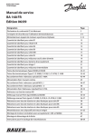
7.6 Replacing the mire
Replacement parts: 32163-3380
1. Remove the left, right and front covers. (See
“5.1” of the AR-630A Service Manual.)
2. Unscrew FC3×10 (n=2) and remove the LED
plate (KM-L).
FC3×10
LED plate
3. Unscrew CK2×5 (n=4) and remove the mire. (KM-L)
4. Fit the parts in reverse order.
* Arrange the cables so as not to interfere with
the optical parts.
5. Perform the auto-tracking and auto-shot
CK2×4
calibration.
2
4
Mire
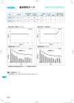
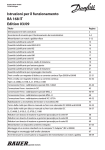
7.7 Replacing the KM LED unit
Replacement parts: 32158-EA42
1. Remove the left, right and front covers. (See
“5.1” of the AR-630A Service Manual.)
2. Unscrew CK1.7×5 (n=4) and FK2×4 (n=4)
and remove the KM LED.
CK1.7×54
FK2×34
KM LED
3. Unscrew CK1.7×5 (n=4) and remove the KM
LED unit.
4. Fit the parts in reverse order.
5. Perform the auto-tracking and auto-shot
calibration.
6. For the layout of LED, see 32163-EA42 in
“9.2”.
Holder
P615
CK1.7×52
CK1.7×52
KM LED unit
7-3
7.8 Replacing the target origin unit
Replacement parts: 32906-EA36
See “7.8” of the AR-630A Service Manual.
7.9 Replacing the CCD camera
Replacement parts: 32903-E001A
See “7.9” of the AR-630A Service Manual.
7.10 Replacing the wheel guide ASSY
Replacement parts: 32903-M5003
See “7.10” of the AR-630A Service Manual.
7.11 Replacing the pinion
Replacement parts: 32903-M138
See “7.11” of the AR-630A Service Manual.
7.12 Replacing the shaft
Replacement parts: 32903-M5003
See “7.12” of the AR-630A Service Manual.
7.13 Replacing the bearing
Replacement parts: 82011-0410A
See “7.13” of the AR-630A Service Manual.
7.14 Replacing the U/D MOTOR unit
Replacement parts: 32906-EA46
See “7.14” of the AR-630A Service Manual.
7.15 Replacing the U/D LIMIT unit
Replacement parts: 32907-EA47
See “7.15” of the AR-630A Service Manual.
7.16 Replacing the measuring unit
Replacement parts: 32163-3000 (3100)
See “7.16” of the AR-630A Service Manual.
7-4
7.17 Replacing the TV monitor
Replacement parts: 32903-E001B
See “7.17” of the AR-630A Service Manual.
7.18 Replacing the LED
Replacement parts: 32906-3110 (for NIDEK INC.: 32159-3110)
See “7.18” of the AR-630A Service Manual.
7.19 Replacing the chart LED lamp unit
Replacement parts: 32906-EA15
See “7.19” of the AR-630A Service Manual.
7.20 Replacing the F/B MOTOR unit
Replacement parts: 32909-EA80
See “7.20” of the AR-630A Service Manual.
7.21 Relacing the R/L MOTOR unit
Replacement parts: 32909-EA48
See “7.21” of the AR-630A Service Manual.
7.22 Replacing the printer unit
Replacement parts: 34495-E002
See “6.5” of the AR-630A Service Manual.
7.23 Replacing the TRC LIMIT unit
Replacement parts: 32909-EA81
See “7.23” of the AR-630A Service Manual.
7.24 Replacing the ILLUMI LED unit
Replacement parts: 32909-6200
See “7.24” of the AR-630A Service Manual.
§8
ADJUSTMENT
8.1 Optical axis adjustment of phototransmitter/
photoreceptor
8.1.1 Optical axis check of phototransmitter/photoreceptor
See “8.1.1” of the AR-630A Service Manual.
8.1.2 Optical axis adjustment of phototransmitter/photoreceptor
1. Turn the holder of mirror B (1589) to align
the photoreceptor height at the -12D position
with the aperture. (See the figure on page 82 for the -12D position)
Aperture
Photoreceptor
Holder of mirror B
Holder of G8+G9+G10
2. Turn the holder of G8+G9+G10 to align the
photoreceptor height at the +12D position
with the aperture center.
8-2
3. Turn the SPD holder 90º to make the photoreceptor vertical.
4. Move mirror B (1589) to make horizontal alignment of the photoreceptor at the +12D and
-12D positions with the aperture.
* Turn mirror B (1589) at the -12D position, and move parallel at the +12Dposition.
At the -12D position
At the +12D position
Photoreceptor
Photoreceptor
Aperture
Aperture
Mirror B
(1) Tighten the set screws (n=3) on top of the
mirror B (1589) holder evenly, paying
attention to the displacement in the
horizontal direction.
(2) If there is displacement in the vertical
direction, make adjustment by turning the
mirror B (1589) holder again.
(3) Mirror B (1589) is not out of the holder.
5. Turn the SPD holder and make sure that the
photoreceptor is always at the aperture
center.
Mirror B
8-3
8.2 Optical axis adjustment of chart
8.2.1 Optical axis check of chart
1. Put a piece of white paper in front of the measuring LED.
2. Attach the optical axis adjustment jig (ARMJ-7).
3. Set DIP switch No. 4 to the ON position and turn the system ON.
4. Press
(R/K button).
5. Look into G8+G9+G10 through the -12D magnifier and move the sensor carry and chart
carry until the chart is focused.
REFERENCE
• Where both chart and aperture of the sensor carry are focused, looking into G8+G9+G10
with the naked eye
0D position
• Where both the chart and aperture of the sensor carry are focused, looking into
G8+G9+G10 with the +12D magnifier
-12D position
• Where both the chart and aperture of the sensor carry are focused, looking into
G8+G9+G10 with the -12D magnifier
+12D position
G6+G7
Sensor carry
G8+G9+G10
Chart (3130)
Chart carry
-12D
0D
+12D
8-4
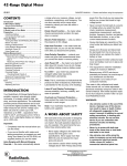
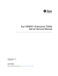
8.2.2 Adjustment of chart in vertical direction
1. Turn the holder of G6+G7 to align the chart height at the +12D and -12D positions with
the aperture center.
* Check at the 0D position as well.
Aperture
Chart
G6+G7
G6+G7
8.2.3 Adjustment of chart in horizontal direction
See “8.2.3” of the AR-630A Service Manual.
8.3 Three-point relationship among SPD, mask and LED
8.3.1 Check of the three-point relationship among SPD, mask
and LED
See “8.3.1” of the AR-630A Service Manual.
8.3.2 Perpendicular adjustment of the SPD and mask
photoreceptor
See “8.3.2” of the AR-630A Service Manual.
8-5
8.3.3 Tilt adjustment of LED lights and mask photoreceptor
1. Set DIP switches No. 4 and No. 5 on the BA01
board to the ON position.
2. Turn the power switch ON and press
Mask unit
(R/
K button) .
Press the Start button on the joystick to place
the system in “Test mode 1”.
3. Put a piece of white paper between the sensor
carry (5035) and relay lens (5043).
* The paper must be tilted so that reflected light
will come into the mask unit.
* The white paper makes it easy to see the mask
photoreceptor.
* This adjustment can be made by attaching the
chart LED lamp (EA15) to the relay lens
(5043).
Put a piece of white paper here.
4. Draw out the + power magnifier of the optical axis adjustment jig (ARMJ-7) about 10 cm
and look into G8+G9+G10. Check the positions of the LED lights and mask photoreceptor.
* As the position where one can see varies according to individual eyesight, find the appropriate
position where you are able to see.
5. After the perpendicular adjustment of the
SPD and mask photoreceptor is completed,
attach the LED adjustment jig (RKDJ-1) as
the right figure shows. Verify that the LED
lights are parallel to the mask photoreceptor.
* When the LED adjustment jig (RKDJ-1) is
available, use the LED adjustment jig (RKDJ1) instead of the optical adjustment jig
(ARMJ-7) for this adjustment.
* If the LED lights are not parallel to the mask
photoreceptor, follow steps 6 - 7 to perform
the tilt adjustment of the LED light and mask
photoreceptor.
The LED lights are parallel to the mask photoreceptor.
LED adjustment jig (RKDJ-1)
8-6
6. Loosen HH3×4 (n=2) retaining the LED (3110).
* It makes the SPD and LED turn separately,
and only the LED light turns.
HH2×4 (n=2) retaining the LED
7. Look into G8+G9+G10 with the + power magnifier of the optical adjustment jig (ARMJ7) and turn the LED until the LED lights are parallel to the mask photoreceptor.
LED light
Mask photoreceptor
The LED lights are not parallel
to the mask photoreceptor.
The LED lights are parallel to the
mask photoreceptor.
8. Loosen HH3×4 (n=2) retaining the LED.
When the LED lights have become parallel
to the mask photoreceptor, make sure that
the LED lights are positioned in the middle
of the mask photoreceptor as the right figure
shows.
If not, perform “8.3.4 LED adjustment in the
middle”.
The LED lights are positioned in the
middle of the mask photoreceptor.
8.3.4 LED adjustment in the middle
See “8.3.4” of the AR-630A Service Manual.
8.3.5 Check after adjustment of three-point relationship among
SPD, mask and LED
See “8.3.5” of the AR-630A Service Manual.
8-7
8.4 Position adjustment of target and LED lights
See “8.4” of the AR-630A Service Manual.
8.5 CYL value adjustment
See “8.5” of the AR-630A Service Manual.
8.5.1 When the height of the side-by-side waveforms is different
1. Set DIP switches No. 4 to the ON position
and No. 5 to the OFF position, and press
(IOL button).
DIP switch on the BA01 board
2. Align the system with the -10D model eye.
3. Press the START button on the joystick twice
to establish “Test mode 2”.
4. Set the SPD unit (5047) to the 90º position
(left side).
5. Adjust VR3 or VR4 on the BA06 board so
that the side-by-side waveforms will become
the same height on the oscilloscope display
signal.
* With both VR3 and VR4 fully turned
counterclockwise, adjust the light quantity to
low.
6. When the height of the side-by-side
waveforms becomes the same, make sure
that the waveforms between CH1 and CH2
are equal in amplitude.
7. If not, perform “8.5.2 Optical axis adjustment
of phototransmitter/photoreceptor system in
horizontal direction”.
VR3 and VR4 on the BA06 board
CH1
CH2
8-8
8.5.2 Optical axis adjustment of phototransmitter/photoreceptor
system in horizontal direction
See “8.5.2” of the AR-630A Service Manual.
8.5.3 Optical axis adjustment of phototransmitter/photoreceptor
system in vertical direction
See “8.5.3” of the AR-630A Service Manual.
8.5.4 Check after waveform adjustment
See “8.5.4” of the AR-630A Service Manual.
8.6 Measurable range adjustment
See “8.6” of the AR-630A Service Manual.
8.7 SPH value calibration
See “8.7” of the AR-630A Service Manual.
8.8 AR AXIS adjustment
See “8.8” of the AR-630A Service Manual.
8.9 IOL check
Check that the measurement can be performed in the IOL mode.
1. Attach the non-cemented model eye (RKDJ1 0900).
2. Press
(Eyeprint button).
3. Align the system with the +10D model eye
and slightly defocus by pushing in the
focusing direction, and make sure that an
error does not occur when two spots are
measured in each direction.
: Position to be measured
8-9
8.10 Chart calibration
1. Adjust the visibility of the dioptric tester.
2. Attach the chart calibration jig (ARMJ-6) and turn its rotor plate to align with the model
eye for alignment.
3. Set DIP switch No. 4 on the BA01 board to
the ON position.
4. Press
(Change button), then press the
START button to place the system in
“MODE 12-0”.
5. Move the main body forward and backward
to align with the model eye.
6. Set the rotor plate of the jig in the hole with
nothing in it. (0D position adjustment)
7. Look into the dioptric tester to bring the chart
in focus.
* Pressing
(Change button) increases the value.
* Pressing
(R/K button) decreases the value.
* Bring the chart in focus, adjusting from the + side.
8. Press
(Change button), then press the START button to establish “MODE 12-1”.
* The button operation is the same as in “MODE 12-0”.
9. Press the START button to establish “MODE 12-2”.
10. Turn the rotor plate of the jig to align with the +12D lens. Press
(Print button) to
bring the chart into focus (+12.00: +12D position adjustment)
* The button operation is the same as in “MODE 12-0”.
* The value when focus is achieved must be between +11.80 and +12.20. If not, establish
“MODE 12-1” again and fine-adjust the value.
* Increase the value if the absolute value is small and decrease the value if it is large.
11. Perform the -12D position adjustment by the same procedure as step 10.
* The value when focus is achieved must be between -12.20 and -11.80. If not, establish
“MODE 12-1” again and fine-adjust the value.
* Increase the value if the absolute value is small and decrease the value if it is large.
12. When the -12D or +12D position cannot be
Increase parameter V.
adjusted (the line does not become straight)
by the above adjustment, establish “MODE
12-0” and change parameter V.
㪂㪈㪉㪛
Decrease parameter V.
13. After the adjustment, remove the chart
calibration jig.
㪂㪈㪉㪛
㪄㪈㪉㪛
㪄㪈㪉㪛
8 - 10
8.11 Internal reflection check
See “8.11” of the AR-630A Service Manual.
8.12 Tilt adjustment of Chart
See “8.12” of the AR-630A Service Manual.
8.13 PD adjustment
8.13.1 PD adjustment
1. Attach the center PD check jig onto the chin
rest.
* The scale must be parallel to the target.
* The mark position of the scale must agree
with the Eye line marker.
2. When the main body is fixed by the knob,
make sure that the center deviation is within
2 mm (3mm for test).
* Make this adjustment after turning the power
OFF and then on again.
3. Turn OFF the power switch.
4. Press %;. (CYL Mode Change button) and
(Eyeprint button) simultaneously, then
turn ON the power switch.
5. Press the START button to establish “MODE
13-1”
6. Fix the main body by the knob and match the center of the scale with the one of the target.
Then, move the main body from the center of the scale to the left and right evenly and
press
(Print button) to measure 64 mm and 80 mm.
Adjust the gain with
(UP button) and
(DOWN button) so that the shift lengths at 64
mm and 80 mm are almost the same.
7. Press
(Print button).
8. Press
(Setting button).
9. Press
%;.
(CYL Mode Change button) and
(Eyeprint button) simultaneously.
8 - 11
8.13.2 PD (64 mm and 80 mm) offset adjustment
1. Press the START button to establish “MODE 13-2”.
2. Adjust the offset with
(UP button) and
(DOWN button) until the measured value on
the monitor becomes 64.0 ± 0.9 (for PD 64 mm) and 80.0 ± 1.0 (for PD 80 mm).
3. Press
(Setting button).
4. Press %;. (CYL Mode Change button) and
(Eyeprint button) simultaneously to save the
parameter.
8.14 Auto-tracking adjustment
Perform this adjustment in the state that the front cover is attached.
8.14.1 R/L adjustment
1. Set DIP switch No. 4 to the ON position and turn ON the power switch to establish “MODE
31-0” for adjustment.
2. Measure the clearance between the front cover and M084 with a steel scale and manipulate
the joystick until the clearance becomes 2.5 mm.
㧞㧡㨙㨙
3. Adjust the sensor plate (M822) to the position where the LIMIT on the TV monitor changes
from 0 to 1 and fix it.
* Adjust both the right and left limits so that the LIMIT on the TV monitor changes from 0 to 1
when the clearance is 2.5 mm.
* The difference between the right and left clearances must be within 0.5 mm. (e.g. 2 mm and
2.5 mm, 2.5 mm and 3 mm)
4. Press
(UP button) and
(DOWN button)
and make sure that the difference between
the clearances is 1 mm or less when moving
the measuring unit to the right LIMIT and
left LIMIT.
Sensor plate
8 - 12
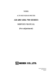
8.14.2 F/B adjustment
1. Establish “MODE 31-1” for adjustment and
press the START button once.
2. Measure the clearance between the front
cover and M084 with a steel scale and
manipulate the joystick until the clearance
becomes 2 mm.
3. Hold the front cover by hand and measure
the clearance between the front cover and
M084 where there is no opening between the
front plate (M302) and front cover.
4. Fix the sensor plate (M815) where the LIMIT
on the monitor changes from 0 to 1.
5. Press
(UP button) and
(DOWN button)
to move the measuring unit to the limit
position and make sure that the clearance
between the front cover and M084 is 2 mm.
(The difference must be 1 mm or less.)
M815
8 - 13
8.15 Auto-shot adjustment
See “8.15” of the AR-630A Service Manual.
8.16 Adjusting the up-and-down movement of the
measuring unit
8.16.1 Adjusting the tightness of the nut stopper
See “8.16.1” of the AR-630A Service Manual.
8.16.2 Adjusting the tightness of the screws retaining the updown bearings
See “8.16.2” of the AR-630A Service Manual.
8.16.3 Adjusting the lead screw for up-and-down movement
See “8.16.3” of the AR-630A Service Manual.
8.17 Cleaning the measuring window
See “8.17” of the AR-630A Service Manual.
8.18 Cleaning the model eyes and steel balls
See “8.18” of the AR-630A Service Manual.
8 - 14
8.19 Tracking and auto-shot calibration
1. Set DIP switch No. 4 to the ON position.
2. Follow the instructions below to establish “TRC ADJUST MODE”.
3. Press the power switch while holding down
(Eyeprint button) and %;. (CYL Mode
Change button).
4. Attach the model eye.
5. Press
(3D Auto button) to establish “TRC
Mire ring
ADJUST MODE 30”.
6. Align the mire ring with the target and adjust
the focus properly, then press
(View
Comparison button).
* Align the mire ring to the center of the target
and visually obtain focus.
8.20 Setting the mask blink level
1. Establish “MODE 14” and set the value to +410 (2.5V) with
(Change button) and
(R/K button).
8.21 Setting print density
1. Turn ON the power switch.
2. Set DIP switch No. 3 on the BA01 board to
the ON position to establish “MODE 10”.
3. Change the value with
(Change button)
and
(R/K button) (the value changes in
the -1.00 to +1.00 range in increments of 1)
and print out the data with
(Print button)
to check the printout for density.
<Test print pattern>
!"#$%&'()*+,-./01
23456789:;<=>?χω٠#$%&'()
*+,-./0123456789:;<
.ψ
ع㨫㨬㨭㨮㨯㨰㨻㨼㨽㨾㨿㩞㩟㩠㩌㨺㨻㨼㨽㨿㩀㩁
㩂㩃㩄㩅㩆㩇㩈㩉㩊㩋㩌㩍㩎㩏㩐㩑㩒㩓㩔㩕㩗㩘㩙
㩚㩛㩜㩝㩞㩟㩠㩡㩢㩣㩤㩥㩦㩧
NOTE
• Normally set the data to “000”.
Setting a positive value will slow down the printing speed and increase the print
density.
• Do not set the value larger than necessary.
Setting the value too large may affect the life of the printer head.
8 - 15
8.22 Replacing the printer unit
See “6.5 Replacing the BA28 board” of the AR-630A Service Manual.
8.23 Setting sensor offset
See “8.22” of the AR-630A Service Manual.
8.24 Sensor calibration
See “8.23” of the AR-630A Service Manual.
8.25 Setting EEPROM DATA
See “8.24” of the AR-630A Service Manual.
8.26 Adjusting the up-and-down movement of the chin rest
See “8.25” of the AR-630A Service Manual.
8.27 KM calibration
1. Attach the steel ball to the chin rest.
2. Turn ON the power switch while holding
down
(Eyeprint button) and %;. (CYL
Mode Change button). “ADJUST MENU”
mode is established.
* When the covers are removed, set DIP switch
No. 4 to the ON position and turn ON the
power switch to establish the “ADJUST
MENU” mode.
3. Press
(R/K button) to select “KM AUTO
CALIBRATION”.
4. Press
(DOWN button).
8 - 16
5. Perform the calibration with the steel balls
of R5.95 mm, R7.94 mm and R9.13 mm.
6. Press
(Setting button) to establish
“ADJUST MENU” mode.
7. Press
(Eyeprint button) and
%;.
(CYL
Mode Change button) simultaneously to
store the data obtained by the adjustment.
* When the covers are removed, set DIP switch No. 4 to the OFF position to store the data
obtained by the adjustment and exit from the “ADJUSMENT MENU” mode.
8. Select the auto-tracking and measure the steel balls of R5.95 mm, R7.94 mm and R9.13
mm.
* If the measured value is out of the tolerance (nominal value ± 0.02), follow the instructions
below to adjust the GAIN so that the value becomes within the tolerance.
(1) Establish “ADJUST MENU” mode as in
step 2.
(R/K button) to select “KM AUTO
(2) Press
CALIBRATION”.
(3) Press
(UP button) to establish the
“CORRECT” mode.
(4) For each steel ball of R5.95 mm, R7.94 mm
and R9.13 mm, decrease the value if the
measured value is large and increase the
value if it is small.
* The last three digits of 1.0000 magnification are indicated on the monitor.
[e.g.] When the value is “1.0200,” “200” is indicated on the monitor.
(5) Press
(Setting button) to establish the “ADJUST MENU” mode.
(6) Store the data obtained by the adjustment as in step 7.
'#
(Common part
for AR-9A)
(Common part for KV-1)
(Common part
for KV-1)
$#
(Common part
for AR-9A)
(Common part
for AR-9A)
IC card
(Common part for AR-2C)
§9
REFERENCE
9.1 Wiring Diagram
9-2
9.2 Connecting Cables
32907-EA03
2
$40
59
4'&
59
140
59
;'.
59
)40
()0&
,
$#
32906-EA15
%*#46.'&.#/2
2
4 ǡ
9*6
$.-
#4#2%
34495-EA15
2
$.$.$.$.$.$.$.-
4'&
4'&
4'&
4'&
4'&
4'&
4'&
2
2
9-3
32907-EA19
$#
$40
2
9*6
;'.
)40
$.7
$40
4'&
64
64
4
&
4
$.-
&
$#
32185-EA20
/+4'.'&
2
$40
4'&
$.-
7.#9)Z
()
59
$#
4-#2%
9-4
32906-EA24
2&.'&
2&.'&
$40
4'&
&.5() 4
,
&.5() 4
2
$1661/8+'9
#
&&
$#
32909-EA31
2
#
$
#
$
#
$
#
$
#
$
#
$
#
$
#
$
#
$
#
$
#
$
#
$
#
$
#
$
#
$
2
(#8
('44+6'%14'
'
(((:::
QT(((5:::
#
$
#
$
#
$
#
$
#
$
#
$
#
$
#
$
#
$
#
$
#
$
#
$
#
$
#
$
#
$
%
9-5
32906-EA33
2
2
2
2
32906-EA34
#
$
#
$
#
$
#
$
#
$
#
$
#
$
#
$
#
$
#
$
('44+6'%14'
'
(((:::
QT(((5:::
32906-EA36
#4#2%
2
$40
4'&
140
;'.
2+6.2#
32906-EA41
$#
&
&
4'&
$.-
9*6
2
&
$#
&
9-6
32163-EA42
2
$40
4'&
140
;'.
)40
$.7
8+1
)4;
-/.'&
85(0Z
'*4
7
. /GCUWTKPI 4
YKPFQY
&
8KGYGFHTQOVJGRCVKGPVUUKFG㧕
32907-EA46
㧗
㧙
㧗
2
)4;
$.-
/
7&/1614
'
㧙
32909-EA47
0%
2
$40
4'&
140
;'.
%
01
72&190
722'4.+/+6
0%
%
01
72&190
.19'4.+/+6
32909-EA48
㧗
㧙
2
㧗
8+1
$.-
/
4.A/1614
'
㧙
9-7
32906-EA54
%
%
;'.
9*6
$.
'#2
4'&
)40
$.7
.'*62
㧔%QPVCEVRKP㧕
'
%
32906-EA55
2
;'.
9*6
$.4'&
)40
$.7
$40
4'&
140
;'.
%
%
416#6142/
'#
#4#2%
32906-EA57
2
4'&
9*6
'
,%5-ǡ
32906-EA58
㧙
2
㧙
㧗
$.7
$.-
4
ǡ9
'
/
㧗
9-8
32909-EA59
('44+6'%14'
'
(((:::
QT(((5:::
('44+6'%14'
'
(((:::
QT(((5:::
2
2
8*40
)4;
9*6
,
2
2
#
$
#
$
#
$
#
$
#
$
#
$
#
$
#
$
2
#
$
#
$
#
$
#
$
#
$
#
$
#
$
#
$
2
32906-EA60
2
#
$
#
$
#
$
#
$
#
$
#
$
#
$
#
$
2
#
$
#
$
#
$
#
$
#
$
#
$
#
$
#
$
9-9
32906-EA64
2
#
$
#
$
#
$
#
$
#
$
#
$
#
$
#
$
#
$
#
$
#
$
#
$
#
$
#
$
#
$
#
$
#
$
#
$
#
$
#
$
2
#
$
#
$
#
$
#
$
#
$
#
$
#
$
#
$
#
$
#
$
#
$
#
$
#
$
#
$
#
$
#
$
#
$
#
$
#
$
#
$
9 - 10
32909-EA65
,
$40
4'&
140
;'.
)40
45%+(%100'%614
+0
'
2
()
32906-EA67
ǡ9Z
2
32909-EA80
㧗
㧙
2
㧗
9*6
$.-
/
($A/1614
'
㧙
9 - 11
32909-EA81
$#
2
2+6.2#
$40
140
4..+/+6
;'.
4'&
2+6.2#
4.
$#
2+6.2#
)40
$.7
8+1
)4;
($
2+6.2#
($.+/+6
9 - 12
9.3 Configuration
Measuring unit
Main body
TV Monitor
Start Button
Display Panel
Joystick
Memory Indicator
AUX. Button Cover
Print Button (Clear Button)
Change Button
Locking Knob
R/K Button
Base unit
IOL Button
Power Switch
Printer
3D Auto Button
UP Button
View Comparison Button
DOWN Button
Contrast Control
Brightness Control
Setting Button
CYL Mode
Change Button
Eyeprint Button
[Auxiliary Buttons]
9 - 13
Forehead Rest
Measuring Window
Eye Level Marker
LED for Corneal Illumination
Chin Rest
PD Window
Chin Rest Knob
[Top view]
TV Monitor H Control
[Underside view]
TV Monitor V Control
Interface Connectors
Fuses
Power Inlet
[Bottom]
9 - 14
9.4 Labels
or
(Only marketing for
NIDEK INCORPORATED)
or
or
9 - 15
9.5 Error code table
Error code
1
2
3
4
5
6
7
9
A
B
C
D
11
12
13
14
15
16
18
19
1A
1B
1C
81
82
83
84
85
86
87
88
91
92
93
94
A1
A2
A3
A4
B1
B2
B3
B4
B5
B6
C1
Indication
No code
Code
Err
Err1
Err
Err2
Err
Err3
Err
Err4
Err
Err5
Err
Err6
Err
Err7
Err
Err9
Err
Erra
Err
Errb
Err
Errc
Err
Errd
ErrIF
Err11
ErrIF
Err12
ErrIF
Err13
ErrIF
Err14
ErrIF
Err15
ErrIF
Err16
ErrIF
Err18
ErrIF
Err19
ErrIF
Err1a
ErrIF
Err1b
ErrIF
Err1c
Err
Err81
Err
Err82
Err
Err83
Err
Err84
Err
Err85
Err
Err86
Err
Err87
Err
Err88
Err+o
Err91
Err-o
Err92
Errco
Err93
Err
Err94
ERROR
ERROR A1
ERROR
ERROR A2
ERROR
ERROR A3
ERROR
ERROR A4
ERROR
ERROR B1
ERROR
ERROR B2
ERROR
ERROR B3
ERROR
ERROR B4
ERROR
ERROR B5
ERROR
ERROR B6
ERROR
ERROR C1
Contents
Sensor error
Target error
Rotator error
Chart error
CL1 error
CL2 error
Printer error
EEPROM error
RAM error
TV camera error
PC22 communication error
CLOCK error
DSR error (OUT)
DSR error (OUT)
Data error (OUT)
Overflow (OUT)
Command error (OUT)
Data empty (OUT)
DSR error (IN)
DSR error (IN)
Data error (IN)
Overflow (IN)
Command error (IN)
Blink error
Blink error
Blink error
SGRAD error
Blink error
Blink error
Blink error
Alignment error
SPH + failure
SPH - failure
CYL failure
Confident coefficient error
Insufficient light intensity of CCD
Insufficient edge of CCD
Excessive edge of CCD
CCD waveform error
R (corneal curvature) + failure
R (corneal curvature) - failure
CYL (cornea) failure
Focusing error (too near)
Focusing error (too far)
Focusing error (undetectable)
Insufficient Sagittal number
Details of the error
Improper moving distance of sensor
The target limit switch does not turn on.
The rotator limit switch does not turn on.
The chart sensor does not turn on.
The cylinder lens 1 sensor does not turn on.
The cylinder lens 2 sensor does not turn on.
Paper out or lever remains up. (at line printing)
EEPROM data is corrupted.
Backup data of RAM is corrupted.
No synchorizing signal
Communication with PC22 board cannot be done.
Abnormal clock data
DSR is not set when SD command is received.
DSR is not set when data is transmitted.
Data is not received.
Reception buffer is full.
Indecipherable command is received.
There is no data to be sent.
DSR is not set when SD command is received.
DSR is not set when data is transmitted.
Data is not received.
Reception buffer is full.
Indecipherable command is received.
Blink error by mask signal
Blink error 2 by mask signal
Blink error by SGRAD waveform
Error by gradient coefficient
Blink error by mask signal during measurement
Blink error by measuring waveform during measurement
Blink error by measured results
Improper alignment after AR measurement
(When VD is 12 mm) +23D or more
(When VD is 12 mm) -18D or less
(When VD is 12 mm) 8D or less
KM measurement light fails to be detected by CCD. (0)
2 or less KM measurement lights are detected by CCD.
5 or more KM measurement lights are detected by CCD.
Layout of the KM measurement light detected by CCD is abnormal.
13.11 mm or more
4.94 mm or less
12.00D or more
Focus is too near the patient's eye during KM measurement.
Focus is too far the patient's eye during KM measurement.
Focus cannot be detected during KM measurement.
Sagittal number is insufficient for calculating the eccentricity.
* The error codes 9 and A are output to a printout as well.
Error code 9: MemoryFailureonEEPROM
Error code A: MemoryFailureonRAM
9 - 16
9.6 List of jigs, tools and consumables
• Optical axis adjustment jig
• LED adjustment jig
• Chart calibration jig
• Center PD check jig
• Model eye
• Set of Phillips screwdrivers
• Set of flathead screwdrivers
• Penlight
• Blower
• Thin stick (Chopstick)
• Hexagonal wrench
• Needle nose pliers
• Nipper
• Wire stripper
• Soldering iron
• Tweezers
• Set of precision screwdrivers
• Screwdriver for industrial use
• Multimeter
• Lens cleaning paper
• Alcohol solution
• Thread-locking adhesive
• Heat shrinkage tube
• Japanese special paper (Gampi-shi)
• Rubber bond
• Silicon bond
• Tin solder
* Specifications and design are subject to change without notice for improvement.
HEAD OFFICE
TOKYO OFFICE
(International Div.)
NIDEK INCORPORATED
NIDEK SOCIÉTÉ ANONYME
(Représentant Autorisé)
: 34-14, Maehama, Hiroishi-cho, Gamagori, Aichi 443-0038, Japan
Telephone: (0533) 67-6611
Facsimile: (0533) 67-6610
: 6th Floor, Takahashi Bldg., No.2, 3-chome, Kanda-jinboucho
Chiyoda-ku, Tokyo 101-0051, Japan
Telephone: (03) 3288-0571
Facsimile: (03) 3288-0570
Telex: 2226647 NIDEK J
: 47651 Westinghouse Drive Fremont, California 94539, U. S. A.
Telephone: (510) 226-5700
Facsimile: (510) 226-5750
: Europarc 13, rue Auguste Perret, 94042 CRETEIL, France
Telephone: (01) 49 80 97 97
Facsimile: (01) 49 80 32 08