1
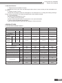
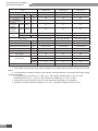
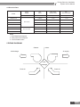
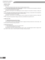
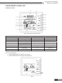
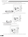
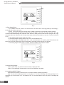
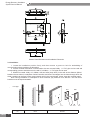
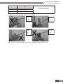
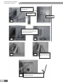
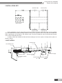
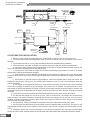
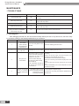
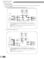
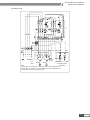
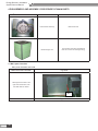
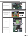
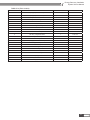
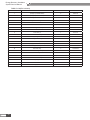
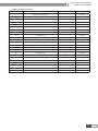
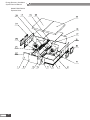
Energy-Recovery Ventilation System
Service Manual
( GC201110-I )
Energy-Recovery Ventilation
System Service Manual
Contents
PRODUCT ................................................................................................ 2
1 MODELS LIST .....................................................................................................2
2 NOMENCLATURE................................................................................................2
3 FEATURES...........................................................................................................2
4 PRODUCT DATA..................................................................................................3
5 PIPING DIAGRAM................................................................................................5
CONTROL................................................................................................. 7
1 OPERATION FLOWCHART.................................................................................7
2 MAIN LOGIC........................................................................................................8
3 WIRED REMOTE CONTROLLER........................................................................9
INSTALLATION....................................................................................... 18
1 DIMENSION DATA ............................................................................................18
2 INSTALLATION SITE ........................................................................................19
3 UNIT INSTALL....................................................................................................19
4 CAUTIONS FOR INSTALLATION .....................................................................20
5 ELECTRIC WIRING WORK...............................................................................21
MAINTENANCE...................................................................................... 24
1 TROUBLE TABLE .............................................................................................24
2 FLOW CHART OF TROUBLE SHOOTING ......................................................25
3 WIRING DIADRAM ............................................................................................26
4 DISASSEMBLY AND ASSEMBLY PROCEDURE OF MAIN PARTS................28
5 EXPLODED VIEWS AND PART LIST................................................................30
II
Energy-Recovery Ventilation
System Service Manual
PRODUCT
1
PRODUCT
Energy-Recovery Ventilation
System Service Manual
PRODUCT
1 MODELS LIST
1.1 Outdoor Unit
Model
Code
FHBQ-D3.5-K
EH01100010
FHBQ-D5-K
EH01100020
FHBQ-D8-K
EH01100030
FHBQ-D10-K
EH01100040
External Static
Pressure (Pa)
Air Flow(m3/h)
H
350
H
100
M
260
M
80
L
210
L
60
H
500
H
100
M
380
M
80
L
300
L
60
H
800
H
110
M
600
M
85
L
480
L
65
H
1000
H
110
M
750
M
85
L
600
L
65
Power
Supply
Appearance
220V
50Hz~
FHBQ-D15-M
EH01100050
1500
150
380V3N~
50Hz
FHBQ-D20-M
EH01100060
2000
150
380V3N~
50Hz
FHBQ-D30-M
EH01100070
3000
220
380V3N~
50Hz
2 NOMENCLATURE
FH
B
Q
1
2
3
-
D
3.5
4
5
NO.
Description
Options
1
The symbol of energy
recovery ventilation
/
2
The structure of heat exchanger
board
3
The diathermanous mode
Total heat exchange
4
The mode of installation
Celling mounted type
5
Nominal Air Flow
3.5:350m3/h;5:500 m3/h;
…… ;30:3000 m3/h
6
The phase of power supply
K: single-phase;
M:three- phase
-
K
6
3 FEATURES
3.1 Description
Our living environments are more and more affected by modern civilization. As the application of airconditioning system and various composite materials, popularization of office equipments and development of
closeness of constructions and for the purpose of energy saving and reduction of cost which cause decrease of
fresh air volume, harmful gas and pollution of creature won’t be diluted properly and replaced. Healthy, energysaving, simple and reliable fresh-air system and equipment has been the focus for engineers and users. Gree
energy recovery ventilation system has solved this problem. This kind of system has two-way air exchange
function so that the change of indoor temp is little during air exchange. The indoor air can be efficiently filtered
by the air filter. New technology and new materials and special technique applied in the unit can ensure low
energy consumption, great performance ,low noise and easy installation.
PRODUCT
2
Energy-Recovery Ventilation
System Service Manual
3.2 Standard Features
1. Replacement and Ventilation Function
It introduces fresh air into room and discharges indoor airout of room to make you feel comfortable as in
the nature.
2. Energy-recovery Function
Internal heat exchanger makes the discharged air and introduced air for cooling and heating exchange.
Energy-recovery rate above 70% keeps heat preservation and ventilation realized.
3. Low-noise Design
Special low-noise ventilation fan is set.
4. Air Filtration and Purge Function
Internal air filter keeps the fresh air introduced into room pure and dustless.
5. Various Series and Multiple Specifications
There are various series to match with the buildings of various structures.
4 PRODUCT DATA
4.1 Product Data at Rated Condition
Model
Code
FHBQ-D3.5-K
FHBQ-D5-K
FHBQ-D8-K
FHBQ-D10-K
EH01100010
EH01100020
EH01100030
EH01100040
3
Air flow Volume
H-M-L
m /h
360-260-210
500-380-300
800-600-480
1000-750-600
External Statics Pressure
H-M-L
Pa
100-80-60
100-80-60
110-85-65
110-85-65
H-M-L
%
71-73-75
68-70-72
70-72-74
75-77-79
H-M-L
%
65-67-68
62-64-65
63-65-67
66-68-70
H-M-L
%
61-63-65
57-59-61
60-62-64
62-64-65
3
3
3
3
Temperature
exchange efficiency
Enthalpy
exchange
Heating
efficiency
Enthalpy
exchange
Cooling
efficiency
Quantity
Recommended
wiring
Area
mm
2
Power Supply
1.0
1.0
1.0
1.0
220~240V~1Ph50Hz
220~240V~1Ph50Hz
220~240V~1Ph50Hz
220~240V~1Ph50Hz
Power Input
W
165
262
400
440
Sound Pressure level
dB(A)
37
39
45
46
Outline Dimension (W X D X H)
mm
800X879X306
800X879X306
832X1016X380
832X1016X380
Package Dimension (WX D X H)
mm
1050X1165X315
1050X1165X315
1087X1320X400
1087X1320X400
Net. Weight
kg
45
45
57
57
Gross weight
kg
53
53
66.5
66.5
20'GP
63
63
40
40
40'GP
147
147
85
59
40'HQ
168
168
104
67
Z5N15
Z5N15
Z5N15
Z5N15
Loading quantity
Standard wired remote controller
3
PRODUCT
Energy-Recovery Ventilation
System Service Manual
Model
Code
FHBQ-D15-M
FHBQ-D20-M
FHBQ-D30-M
EH01100050
EH01100060
EH01100070
3
Air flow Volume
H-M-L
m /h
1500
2000
3000
External Statics Pressure
H-M-L
Pa
150
150
220
H-M-L
%
73
71
70
H-M-L
%
65
62
62
H-M-L
%
60
58
58
5
5
5
1.5
1.5
1.5
380~415V 3N~50Hz
380~415V 3N~50Hz
380~415V 3N~50Hz
Temperature
exchange efficiency
Enthalpy
exchange
Heating
efficiency
Enthalpy
exchange
Cooling
efficiency
Quantity
Recommended
wiring
Area
mm
2
Power Supply
Power Input
W
600
950
2800
Sound Pressure level
dB(A)
48
50
54
Outline Dimension (W X D X H)
mm
1210X1215X452
1210X1215X452
1340X1550X572
Package Dimension (WX D X H)
mm
1550X1540X470
1550X1540X470
1710X1610X700
Net. Weight
kg
100
100
240
Gross weight
kg
115
115
280
20'GP
15
15
9
40'GP
37
37
24
40'HQ
44
44
24
Z5N15
Z5N15
N/A
Loading quantity
Standard wired remote controller
Note:
1. The models of 220v power supply type has 3types of fan speed and the models of 380V have one fan
speed.
2. The temperature exchange efficiency and enthalpy exchange efficiency are tested under these testing
conditions as below:
(1) Cooling efficiency:Indoor air 27 ℃ DB, 19.5℃ WB, outdoor temperature 35℃ DB, 28℃ WB.
(2) Heating efficiency:21 ℃ DB,13℃ WB. Outdoor air temperature: 5 ℃ DB, 2℃ WB.
3. Sound power level according to ISO 5151-sound pressure calculated at 1.5m distance.
4. Operation condition:ambient temperature-15℃ -50℃ ,relevate humidity less than 80% RH.
PRODUCT
4
Energy-Recovery Ventilation
System Service Manual
4.2 Electrical Data
Power
Supply
Fan
Motor
Max. Fuse
Breaker Size
Min.
Disconnect Size
V,Ph,Hz
FLA Each
Amperes
Amperes
0.76A×2
2.47A
1.71A
0.76A×2
2.47A
1.71A
1.0A×2
3.25A
2.25A
FHBQ-D10-K
1.0A×2
3.25A
2.25A
FHBQ-D15-M
1.4A×2
4.55A
3.15A
1.4A×2
4.55A
3.15A
4.2A×2
13.65A
9.45A
Model
FHBQ-D3.5-K
FHBQ-D5-K
220V~50Hz
FHBQ-D8-K
FHBQ-D20-M
380V 3N~50Hz
FHBQ-D30-M
Notes:
1. RLA:Rated load amperes .
2. LRA:Locked rotor amperes .
3. FLA:Full load current .
5 PIPING DIAGRAM
Outdoor
Indoor
Air supply
Air discharge
Heat
exchanger
Fresh air
Room air
5
PRODUCT
Energy-Recovery Ventilation
System Service Manual
CONTROL
CONTROL
6
Energy-Recovery Ventilation
System Service Manual
CONTROL
1 OPERATION FLOWCHART
Bengin
Initialize
N
Air valve checked OK
Y
L0 Error
N
Air valve interface with electricity?
Y
Y
Energy-saving function on
Energy-saving on
N
Y
Timer function on
Timer on
N
Y
Cleaning
N
Remind until the time setting come
Y
Stop or move according to the opposite
humidity, Humidity sensor error display L 1
Humidifying function on?
Judge running
mode?
1
Auto mode
By Pass mode
Heat Exchange
mode
7
CONTROL
Energy-Recovery Ventilation
System Service Manual
2 MAIN LOGIC
2.1 Auto mode
Detect the temperature indoor and outdoor for durative a period of time.
1. The system will operate under by pass mode according to temperature and temperature difference
between room and outdoors is little in transient season.
The system will operate as such request:
By Pass air valve opens, the air discharge fan and air supply fan will operate according to setting fan
speed.
2. The system will operate under heat exchange mode according to temperature and temperature
difference between room and outdoors is large in transient season.
The system will operate as such request:
By Pass air valve closes, the air discharge fan and air supply fan will operate according to setting fan
speed.
3. The system will operate according to the primary mode before the system was off.
2.2 By Pass mode
1. Under By pass mode, air valve is open.
2. The system will operate as such request:
If the air valve is close, the air discharge fan and air supply fan will stop. When the air valve is open , the
fan will operate according to setting fan speed .
2.3 Heat Exchange mode
1. Under Heat Exchange mode, the air valve is close
2. The system will operate as such request:
Electrify the air valve motor, judge the position of the air valve. The air discharge fan and air supply fan will
stop if the air valve is open, or they will operate according to setting fan speed .
CONTROL
8
Energy-Recovery Ventilation
System Service Manual
3 WIRED REMOTE CONTROLLER
3.1 Operation View
Fig.1 Front panel of wired controller
Constitution of wired controller
1
Timer display
9
Cleaning status of filter display
2
Energy-saving status display
10
Mode button
3
Setting humidity display
11
Setting humidity increase button
4
Ambient humidity display
12
Setting humidity decrease button
5
Air exchange mode (half-half air
exchange ,discharge and supply)
13
Fan speed button
6
Fan speed display (high, mid, low)
14
Reset/Switch button
7
Mode(auto, by-pass,
heat exchange)
15
Timer button
8
Error status display
16
On/Off button
1) Turn On / Off the Unit
1. Press ON/OFF button to start the unit. (Fig.2)
2. Press ON/OFF button once again to stop the unit.
Fig.2
9
CONTROL
Energy-Recovery Ventilation
System Service Manual
2) Fan Speed Control (Fig.3,4)(The figureis about relative display area , the same as below)
1. During half-half air exchange, With each press of FAN button, the fan speed will change in the following
order(Fig.3):
Fig.3
2. During air discharge and air supply, with each press of FAN button, the fan speed with switch between
high speed and low peed(Fig.4).
Low
3) Humidity Adjustment (Fig.5)
High
Fig.4
If there is humidifying function in the unit, press humidify button:
▲: Used to increase setting humidity.
▼: Used to decrease setting humidity.
Once press of this button, the temperature will increase or decrease by 5%.
Fig.5
Note: Lock function: Pressing ▲ and ▼simultaneously for 5s, the place of setting humidity will display EE
CONTROL
10
Energy-Recovery Ventilation
System Service Manual
and all response to the buttons Fig.6 will be shielded. And then press ▲ and ▼ simultaneously for 5s to release
Lock Function.
When long-distance monitoring or centralized control shield displayed, the signals of buttons and from
remote controller will be shielded, and CC will be displayed in the place of setting humidity.
Setting range of humidity: 40%~60%RH.
4) Reset/ Switch Function Setting ( Fig.6)
Not having pressed Timer button, long press Reset/ Switch button for 5s to clear operation time and icon.
♦♦ After pressing of Timer button:
Under On status of the unit:
Short press Reset/ Switch button to switch among Timer off setting, Energy saving startup setting,Energy
saving stop setting and Clear time setting.
5) Running Mode Setting (Fig.7)
Fig.6
1. Each press of this button, the operation mode will change as follow,
2. Under Auto mode, the letter of Auto will light, so the system will operate according to temperature
and temperature difference between room and outdoors.
3. Under By pass mode, the letter of By Pass will light, so the fan will operate according to setting Fan
mode and fan speed. Make this mode operate in transient season to prolong service life of the core of heat
exchanger.
4. Under Heat Exchange mode, the letter of Heat Exchangewill light. After shutdown of air valve, the
fan will operate according to setting fan mode and fan speed. Under this mode, the total heat exchange of
temperature and humidity can be realized along with exchange of fresh air, which is energy saving and healthy.
11
CONTROL
Energy-Recovery Ventilation
System Service Manual
6) Timer Setting(Fig.8)
Fig.7
1. In off status of the unit, timer on can be set and in on status, timer off, energy-saving on and energy –
saving off and air clear can be set.
2. Press Timer button into timer setting status. TIMER,Hr and letters corresponding setting will blink.
3. (E.g.during timer off setting, Timer,Hr and OFF will flash).In this case, the user can press ▲or ▼to
increase or decrease setting time. Repress Timer button to make the timer valid and the timing will be Fig.9
calculated after that. When the unit is under timer state, press theTimer button to cancel it. The time interval is
0.5 hr.
4. The setting range of Timer on/off is 0.5-24hr.
5. The setting range of Energy Saving On is 2-5hr and the default is 2hr.
6. The setting range of Energy Saving Off is 1-4hr and the default is 1hr. (Note: press FAN and ▼ at the
same time for 5s only after energy saving timer setting, the energy saving function can operate.
7. The setting range of Timer Clear is 1250hr, 2500hr and 00000.The default is 1250hr.
Fig.8
7) Ambient Temp Display
Under normal state, only indoor ambient humidity is display at ENV.
Notice: The humidifying function with the unit can be valid after it is started.
8) Humidifying ON/OFF Display
Press MODE and ▼at the same time for 5s to switch between humidifying ON/OFF.
Note:The unit with humidifying function can normally run. The indoor humidity and setting humidity can be
displayed only If this function is on. The default is OFF. It is recommended to ON in dry period. The fittings are
optional.
CONTROL
12
Energy-Recovery Ventilation
System Service Manual
9) Fan Mode Display
Press FAN and ▲ at the same time for 5s to switch among half-half air exchange, discharge and supply.
Refer to Fig.2 for details. The fan mode is selected by the users. E.g. plus pressure is needed in the room, fan
mode can be adopted and if negative pressure is needed, air discharge mode can be adopted. Half-half air
exchange is for normal station.
10) Energy Saving Mode Display
Press FAN and ▼ at the same time for 5s to switch between energy saving on/off. If under energy saving
on state, Energy Saving will be displayed. Refer to Fig.2 for details. If the unit needn’t operate for a long time,
energy saving mode can be adopted to meet the demands of both function of fresh air exchange and quality of
indoor air by users.
3.3 Dimension
6
Panel Dimension and Installation Dimension
13
CONTROL
Energy-Recovery Ventilation
System Service Manual
Bottom Panel Dimension and Installation Dimension
3.4 Installation
1. Locate the installation position firstly, and then reserve a groove or hole for embedding of
communication wire according to its dimension.
2. If wired controller and indoor communication wire are mounted visibly, 1 # PVC pipe can be used and
corresponding grooves should be set in the wall. If in hidden, 1 # PVC pipe can be used.
3. Whether mounted visibly or in hidden, drill two holes (keep level) in the wall as the distance (60mm)
between the two holes in underplate of wired controller, and then inset stopper into the holes through which the
wired controller can be fixed. Insert communication wire in the control board. At last, clasp the controller panel.
Note: During installation of underplate of wired controller, pay attention to its direction. The side with 2
breaches must be kept downwards.
PVC pipe
No.
CONTROL
14
Name
Remarks
Energy-Recovery Ventilation
System Service Manual
1
Wall
2
Underplate of wire controller
3
Screw M4X10
4
Controller panel
The appearance of the controller
should be subject to entity.
We must not tear down the panel in these wrong ways as:
From
above
From
below
From
From
right
left
When you want to check the panel ,you need use a screwdriver to tear down it like this:
15
CONTROL
Energy-Recovery Ventilation
System Service Manual
Insert this position with
a screwdriver
Screwdriver
Clip button
①
Circumrotate the screwdriver
clockwise or anticlockwise, the
same to the other side.
②
③
④
⑤
⑥
16
Pull the display board
to make the clip break
off.
Display board and Bottom panel are
separate absolutely.
Energy-Recovery Ventilation
System Service Manual
INSTALLATION
17
Energy-Recovery Ventilation
System Service Manual
INSTALLATION
1 DIMENSION DATA
Fresh
air intlet
Fresh air
outlet
Room air
outlet
Room air
inlet
Uint: mm
Model
A
A1
B
B1
C
C1
D
E
F
G
H
N
FHBQ-D3.5-K
879
823
800
852
306
125
90
125
175
136
416
197
FHBQ-D5-K
879
823
800
852
306
125
90
125
175
136
416
197
FHBQ-D8-K
1016
960
832
884
380
165
90
150
230
155
372
246
FHBQ-D10-K
1016
960
832
884
380
165
90
150
230
155
372
246
FHBQ-D15-M
1215
1159
1210
1262
452
200
100
190
277
178
737
297
FHBQ-D20-M
1215
1159
1210
1262
452
200
100
190
277
178
737
297
L
W
H1
H
electric
box
W2
B
B1
room air inlet
B2
A2
fresh air outlet
room air outlet
flange dimention
W1
fresh air inlet
L1
A
A3
A1
Uint: mm
Model
L
L1
W
W1
W2
H
H1
A
A1
A2
A3
B
B1
B2
FHBQ-D30-M
1550
1650
1340
1310
670
572
249
346
386
180
366
332
372
352
18
Energy-Recovery Ventilation
System Service Manual
2 INSTALLATION SITE
Roomair outlet
Fresh air inlet
Service space
Fresh air outlet
Room air inlet
During installation, the two ducts (fresh air inlet and indoor air outlet) outside the room must be installed
with anti-condensate and heat insulating materials, and the ones inside the room should also be installed with
them if temperature and humidity in the ceiling is high. The ducts outside the room should be kept inclined
1/50~1/30 to avoid water into room.
In order to clean and maintain the filter and heat exchanger core in the system, do keep service space, as
shown in the fig..
3 UNIT INSTALL
Fresh air duct
Air discharge duct
Fresh air inlet
Room air outlet
Exhanst air duct
Insulation materia
Room air inlet
Indoor air
return
Indoor air supply
Fresh air outlet
19
Energy-Recovery Ventilation
System Service Manual
A
inner steer bar
A
ceiling
16hanger
air return
window
room air inletf
outdoor
A-A
diffused set
resh air outle
t
indoor
air duct muffler
room air outlet
fresh air inlet
air duct
muffler
examine and
repair inlet
4 CAUTIONS FOR INSTALLATION
1. Never lay wires, cables and pipes with toxic, inflammable or explosive gas or liquid in the duct.
2. The dismountable ports and adjustable parts of duct and fittings can not be installed in the wall or
floorslab.
3. The sundries and filth in or on the duct and fittings should be cleaned before installation.
4. The construction of bracket or hanger of the duct should accord with the following specifications:
1) The build-in fitting, setting nail or expansion bolt for bracket or hanger should be placed correctly and
firmly .The inlet part should be free of oil soil and painting.
2) The layout of the bracket or hanger should accord with design specifications. If there is no design
specification, following specifications will apply.
a. Pole bracket or inclined bracket is applicable for horizontal duct against wall or pole and support
bracket for that far from wall or pole. Strip hanger is applicable for the duct with diameter or length of side below
400mm.
b. Arm bracket or inclined bracket is applicable for vetical duct against wall or pole and anchor ear
bracket for that far from wall or pole .The vertical pipe outside the room or on the roof should be fixed with
derrick or dragline.
3) The hanger’s rod should be flat and its screw thread should be full and smooth. Either threaded
connection or welding is suitable for joint of hangers. If the former one is adopted, connecting thread of either
end should be longer than diameter of hanger; moreover, anti-loosing measure should be made. If the later one
is adopted, lapping joint is applicable and its length should be 6 times longer than diameter of hanger at least at
two sides.
4) The holes on the bracket and hanger should be drilled mechanically and not with gas cutting.
5. The bracket and hanger can not set at air vent, valve or service door. The hanger can not be directly
fixed at flange. The distance between horizontal duct bracket and hanger can not exceed 4m.If the duct is
installed vertically, the distance between them should not exceed 4m and the built-in fittings of each vertical
duct should be more than 2 pieces.
6. The duct flange, hanger and hanger for equipment should be coated with anticorrosion paint.
7. The floor plate and wall which the duct passes should be repaired after construction. The holes on the
external wall should be kept 2/100 gradient at level direction (the internal is higher) to avoid rainwater into the
room.
8. Installation of duct and connection between air vent and duct should be firm. The frame and decorative
surface should be solid, external surface should be level and indeformable and adjustment should be flexible.
20
Energy-Recovery Ventilation
System Service Manual
5 ELECTRIC WIRING WORK
5.1 Wiring Principle
♦♦ Layout of Wires
1. Layout of wires should accord with national wiring criteria.
2. The power supply must be with rated voltage and special for AC.
3. The power supply should be reliable to prevent terminals from being stressed. Never pull the power
cord forcibly.
4. The line width of power cord must be large enough. Replace the broken power cord or connecting wire
with special cable.
5. All of the electric installation must be performed by professionals according to local laws and
regulations and instructions.
6. The earthing wire should be reliably connected with special earthing device and be performs by
professionals.
7. Air switch and leakage switch which can cut off the general power supply should be installed.
8. The air switch should integrate the functions of magnetic release and hot release to protect it for short
circuit or overload.
The field wiring should be subject to circuit diagram attache d on the unit.
♦♦ Earthing Requirements
1. Reliable earthing measure must be adopted. The yellow green earthing wire with the only use never
can be cut off and fixed with tapping screws to avoid electric shock.
2. Earthing resistance should be accord with the criteria.
3. Power supply must be reliably earthed. The earthing wire can not connect with:
a.Tap water pipe; b. Gas pipe; c. Blowing tube; d. Place which specialist considers unreliable.
5.2 Electric Wiring Design
Aire vavle
One phase units
220V~
Terminal board
Reactive Signal
In-phase Motor
Main
Wire
controller
Board
Temp. sensor
signal
Transformer
21
Energy-Recovery Ventilation
System Service Manual
Three phase Units
380V 3N~
Terminal board
Contactor loop 2
AC contactor 1
AC contactor 2
Contactor loop 1
Fan motor
heat relay
Fan motor
heat relay
Wire
controller
5.3 Specification of Power Supply Wire and Air Switch
220V~,50Hz
Capacity of air
switch (A)
6
Min.sectional area of
earthing wire (mm2)
1.0
Min. sectional area of
power cord (mm2)
1.0
FHBQ-D5-K
220V~,50Hz
6
1.0
1.0
FHBQ-D8-K
220V~,50Hz
6
1.0
1.0
Applied models
Power supply
FHBQ-D3.5-K
FHBQ-D10-K
220V~,50Hz
6
1.0
1.0
FHBQ-D15-M
380V 3N~,50Hz
6
1.0
1.0
FHBQ-D20-M
380V 3N~,50Hz
6
1.0
1.0
FHBQ-D30-M
380V 3N~,50Hz
6
1.0
1.0
Note:
a. The power cord of the unit must be copper cored cable, and working temp can not exceed specified
value.
b. Increase the sectional area of power cord above 15 meters to avoid overload.
22
Energy-Recovery Ventilation
System Service Manual
MAINTENANCE
23
Energy-Recovery Ventilation
System Service Manual
MAINTENANCE
1 TROUBLE TABLE
Error
Error Code
Logic
Communication error.
E6
Communication between the main board and the wire remote controller is
in trouble.
Indoor temp sensor error.
F0
Something is wrong with temp sensor or the temperature is overstep the
range of the temp sensor.
Humidity sensor error.
L1
Humidity sensor is not connected or communication is in trouble.
Outdoor temp sensor error.
F3
Something is wrong with temp sensor or the temperature is overstep the
range of the temp sensor.
Air valve and relevant fitting error
or wrong connection of centralized
control wiring of air valve.
L0
By-pass door and drive structure of the unit loose.
2. Fault Diagnose
After debugging and trial run, the unit can be normally used by the user. If any fault occurs, remove it firstly
by yourself according to the following table before you contact us.
No.
Possible causes
Solutions
Too much dust gathers on the
air filter.
Re-fix the collecting place of air vent.
Noise occurs
at air vent.
Installation of air vent is loose.
Re-fix the collecting place of air vent.
3
The system can
not be started
No power supply or power
cord is incorrectly connected.
Te r m i n a l s o f m a i n b o a r d
transformer are loose.
Communication fault (E6).
Air valve and relative fittings
are faulted(L0).
The centralized controller of
air valve of main board is not
connected(L0).
Repair the power supply and check power cord
according ;
Repair the power supply and check power cord
according to circuit diagram on the unit;
Re-insert and connect transformer terminals;
Check the connecting wire between displayer and main
board;
Check by-pass door and drive structure of the unit and
fix it;
Connect CONTROPL port of main board;with live line or
pinboard of air valve.
4
There is not air from
indoor or outdoor
vent after opening the
switch.
1. No power supply or power
cord is incorrectly connected.
2. Control wire is not or
incorrectly connected.
1. Check power and power supply
2. Check the connecting line between operational box
and main unit.
1
2
24
Phenomenon
Airflow volume
at air outlet/
inlet is obviously
decreased after a
period of time.
Energy-Recovery Ventilation
System Service Manual
2 FLOW CHART OF TROUBLE SHOOTING
Fan stops
opperating
Wired remote controller
display normally?
Power on ?
Y
Y
Error Code
dispalyed?
Y
Refer to the
Operarting
Instruction
Manual
N
N
Motor connection
is normal ?
Y
Check the
connction of
the wires
Maintain and
Power the unit on
N
The
transfirmer
is normal ?
N
Change the
transformer
Y
N
The main borad
can supply
power ?
Change the
main borad
Y
Maintain or change the
wired temote controller
Change the
motor or the
capacitance
25
Energy-Recovery Ventilation
System Service Manual
3 WIRING DIADRAM
United
control
Humidity
sensor
External wiring figure of the unit(If this one is different from wiring figure of junction box, take the wiring box
of junction box as standard) .
1) Model:FHBQ-D3.5-K;FHBQ-D5-K;FHBQ-D8-K;FHBQ-D10-K.
POWER
PE
L
N
Wired
controller
Remote
Control
Humidifier
AC Contactor Coil
Note:
1.When need humidifier,connect "1" and "2" terminal (220V~,1A) to the contactor
coil of the humidifier.Meanwhile,connect the humidification sensor to HUMIDITY terminal
on the main board.
2.Wire the CN9 on the main board to the united control to access a center control to the air
valves.
3.The part with broken line is optional for user.
United
control
Humidity
sensor
2) Model:FHBQ-D15-M;FHBQ-D20-M.
POWER
PE
L1
L2
L3
N
Humidifier
AC Contactor Coil
Wired
controller
Remote
Control
Note:
1.When need humidifier,connect "1" and "2" terminal (220V~,1A) to the contactor
coil of the humidifier.Meanwhile,connect the humidification sensor to HUMIDITY terminal
on the main board.
2.Wire the CN9 on the main board to the united control to access a center control to the air
valves.
3.The part with broken line is optional for user.
26
Energy-Recovery Ventilation
System Service Manual
3) FHBQ-D30-M.
WH
WH
WH
WH
Exhaust
OFF
YE GNRD YE GN RD
POWER
Fan
Motor
YEGN
YEGN
Blower
Motor
Exchange
ON
Controlling switch
(back side)
Note:
1.Press "ON" or "Exchange",L is connected with L1,disconnected with L2;
2.Press "OFF" or "Exhaust", L is connected with L2, disconnected with L1;
3.The broken line part is connected by user.
27
Energy-Recovery Ventilation
System Service Manual
4 DISASSEMBLY AND ASSEMBLY PROCEDURE OF MAIN PARTS
Picture
Name
Function
Acentric Motor Sub-Assy.
Make the air flow.
Heat Exchange core.
The important Sub-Assy that make the
fresh air and room air exchange energy.
4.1 Main parts introduce
Main parts dismantle and install
Name: Service door’s teardown
Fig. show
Discharge the two bolts on the
right of the Service door, and
then take down the buckle.
Bolt
Name: Electric Box’s teardown
28
Fig. show
Energy-Recovery Ventilation
System Service Manual
Capacitance
Remove the two bolts and then
circumgyrate the Electric Box to open it.
Bolt
Name:Change the heat
exchange core and filter
Fig. show
After removing the service door, we could
be able to take out the core and the filter.
The core should be washed by
cleaner or other special dust catcher
equipments except water.
Heat Exchange core
Filter
Fig. show
Name: Motor Sub-Assy’s teardown
Motor Sub-Assy
1.Opening the top cover;
Take out the core and the
filter beforehand.
Air path foam
2. Remove the bolt as the fig. show
and take out the fixing board assy.
3. Take out the air path foam;
Disentwine the nut that used to fix the
fan and pedestal; Remove the bolt that
used to fix the fan and side panel.
Bolt
29
Energy-Recovery Ventilation
System Service Manual
5 EXPLODED VIEWS AND PART LIST
1) Model:FHBQ-D3.5-K;FHBQ-D5-K;FHBQ-D8-K;FHBQ-D10-K FHBQ-D15-M;FHBQ-D20-M.
Exploded View
FHBQ-D3.5-K( EH01100010)Parts List
30
No.
Name
Num.
Code
1
sponge 1( Left Side Plate)
2
12208928
2
sponge 2( Left Side Plate)
1
12208916
3
Assy 2 of Left Side Plate
1
01318902
4
Assy of overhauling door
1
01398902
5
Door Holder
1
02208901
6
Base Plate Assy
1
01288901
7
Retaining Plate Assy
2
01848903
8
Rubber Sheet
2
76718901
9
Foam Assy 3
1
12319813
10
Electric Box Assy
1
01396159
11
Sub-assy of Right Side Plate
1
01311115
12
flange Sub-assy
4
01491142
13
Foam Assy 1
2
12319811
14
sponge(Side of Bottom Plate)
1
12208920
15
By-pass assy
1
07138901
16
Filter Sub-assy
2
11128901
17
heat exchanger assy
2
00908901
18
Foam Assy 2
1
12319812
19
Motor Sub-Assy
2
15408901
20
Cover Plate Assy
1
01268901
21
sponge
1
1220890103
22
Sub-assy 1 of Left Side Plate
1
`01311116
23
Display board
1
30295007
Energy-Recovery Ventilation
System Service Manual
FHBQ-D5-K (EH01100020)
No.
Name
Num.
Code
1
sponge 1( Left Side Plate)
2
12208928
2
sponge 2( Left Side Plate)
1
12208916
3
Assy 2 of Left Side Plate
1
01318902
4
Assy of overhauling door
1
01398902
5
Door Holder
1
02208901
6
Base Plate Assy
1
01288901
7
Retaining Plate Assy
2
01848903
8
Rubber Sheet
2
76718901
9
Foam Assy 3
1
12319813
10
Electric Box Assy
1
01396159
11
Sub-assy of Right Side Plate
1
01311115
12
flange Sub-assy
4
01491142
13
Foam Assy 1
2
12319811
14
sponge(Side of Bottom Plate)
1
12208920
15
By-pass assy
1
07138901
16
Filter Sub-assy
2
11128901
17
heat exchanger assy
2
00908901
18
Foam Assy 2
1
12319812
19
Motor Sub-Assy
2
15408901
20
Cover Plate Assy
1
01268901
21
sponge
1
1220890103
22
Sub-assy 1 of Left Side Plate
1
`01311116
23
Display board
1
30295007
31
Energy-Recovery Ventilation
System Service Manual
FHBQ-D8-K(EH01100030)
32
No.
Name
Num.
Code
1
sponge 1( Left Side Plate)
2
12201137
2
sponge 2( Left Side Plate)
1
12201138
3
Assy of Left Side Plate
1
01311123
4
Assy of overhauling door
1
01391128
5
Door Holder
1
02208901
6
Base Plate Assy
1
02221124
7
Retaining Plate Assy
2
01841108
8
Rubber Sheet
2
76718901
9
Foam Assy 3
1
12311101
10
Electric Box Assy
1
01396160
11
Sub-assy of Right Side Plate
1
01311125
12
flange Sub-assy
4
01491139
13
Foam Assy 1
2
12311103
14
sponge(Side of Bottom Plate)
1
12201141
15
By-pass assy
1
04631124
16
Filter Sub-assy
2
1112800101
17
heat exchanger assy
2
00901101
18
Foam Assy 2
1
12311102
19
Motor Sub-Assy
2
15401109
20
Cover Plate Assy
1
01261109
21
sponge
1
1220113504
22
Sub-assy of Left Side Plate
1
01311116
23
Display board
1
30295007
Energy-Recovery Ventilation
System Service Manual
FHBQ-D10-K(EH01100040)
No.
Name
Num.
Code
1
sponge 1( Left Side Plate)
2
12201137
2
sponge 2( Left Side Plate)
1
12201138
3
Assy of Left Side Plate
1
01311123
4
Assy of overhauling door
1
01391128
5
Door Holder
1
02208901
6
Base Plate Assy
1
02221124
7
Retaining Plate Assy
2
01841108
8
Rubber Sheet
2
76718901
9
Foam Assy 3
1
12311101
10
Electric Box Assy
1
01396160
11
Sub-assy of Right Side Plate
1
01311125
12
flange Sub-assy
4
01491139
13
Foam Assy 1
2
12311103
14
sponge(Side of Bottom Plate)
1
12201141
15
By-pass assy
1
04631124
16
Filter Sub-assy
2
1112800101
17
heat exchanger assy
2
00901101
18
Foam Assy 2
1
12311102
19
Motor Sub-Assy
2
15401109
20
Cover Plate Assy
1
01261109
21
sponge
1
1220113504
22
Sub-assy of Left Side Plate
1
01311116
23
Display board
1
30295007
33
Energy-Recovery Ventilation
System Service Manual
FHBQ-D15-M(EH01100050)
34
No.
Name
Num.
Code
1
sponge 1( Left Side Plate)
2
12201137
2
sponge 2( Left Side Plate)
1
12201138
3
Assy of Left Side Plate
1
01311123
4
Assy of overhauling door
1
01391128
5
Door Holder
1
02208901
6
Base Plate Assy
1
02221124
7
Retaining Plate Assy
2
01841108
8
Rubber Sheet
2
76718901
9
Foam Assy 3
1
12311101
10
Electric Box Assy
1
01396160
11
Sub-assy of Right Side Plate
1
01311125
12
flange Sub-assy
4
01491139
13
Foam Assy 1
2
12311103
14
sponge(Side of Bottom Plate)
1
12201141
15
By-pass assy
1
04631124
16
Filter Sub-assy
2
1112800101
17
heat exchanger assy
2
00901101
18
Foam Assy 2
1
12311102
19
Motor Sub-Assy
2
15401109
20
Cover Plate Assy
1
01261109
21
sponge
1
1220113504
22
/
1
01311116
23
Display board
1
30295007
Energy-Recovery Ventilation
System Service Manual
FHBQ-D20-M(EH01100060)
No.
Name
Num.
Code
1
sponge 1( Left Side Plate)
2
12201137
2
sponge 2( Left Side Plate)
1
12201138
3
Assy of Left Side Plate
1
01311123
4
Assy of overhauling door
1
01391128
5
Door Holder
1
02208901
6
Base Plate Assy
1
02221124
7
Retaining Plate Assy
2
01841108
8
Rubber Sheet
2
76718901
9
Foam Assy 3
1
12311101
10
Electric Box Assy
1
01396160
11
Sub-assy of Right Side Plate
1
01311125
12
flange Sub-assy
4
01491139
13
Foam Assy 1
2
12311103
14
sponge(Side of Bottom Plate)
1
12201141
15
By-pass assy
1
04631124
16
Filter Sub-assy
2
1112800101
17
heat exchanger assy
2
00901101
18
Foam Assy 2
1
12311102
19
Motor Sub-Assy
2
15401109
20
Cover Plate Assy
1
01261109
21
sponge
1
1220113504
22
/
1
01311116
23
Display board
1
30295007
35
Energy-Recovery Ventilation
System Service Manual
Model:FHBQ-D30-M
Exploded View
36
Energy-Recovery Ventilation
System Service Manual
FHBQ-D30-M(EH01100070) Parts List
No.
Name
Num.
Code
1
Front side plate assy 1
1
01398904
2
Assy of overhauling door
1
01318912
3
Electric Box Assy
1
01396168
4
Filter Sub-ass
4
11128001
5
Front side plate assy 2
1
01316080
6
Hanger crossbeam
2
01871226
7
Bottom plate assy
1
02228904
8
Rubber gasket
8
76018401
9
Hanger longeron Sub-assy
2
01871224
10
Acentric motor
2
15706001
11
Air inlet/outlet assy
4
01491143
12
Side plate(air outlet)
2
01318918
13
Clapboard assy 1
1
01248901
14
Back side plate assy
1
01318909
15
Top cover plate 1
1
01268906
16
Top cover plate 2
1
01268907
17
Middle clapboard assy 1
1
01248909
18
Clapboard assy 2
1
01248905
19
Connection plate(top cover)
1
01341105
20
Guide groove(top cover)
1
02281115
21
Heat exchange core
2
49018903
22
Fan retaining rack Sub-assy
2
01848905
23
Guide groove(filter)
1
02281112
37
JF00300198


![ANALISIS PREOPERACIONAL V-0 [Modo de compatibilidad]](http://vs1.manualzilla.com/store/data/006166860_1-178cf12cc661e06e07159f861d3c85bb-150x150.png)