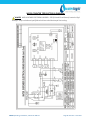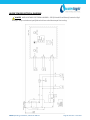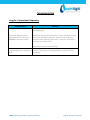
1
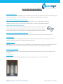
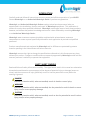
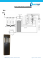
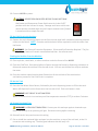
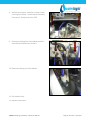
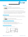
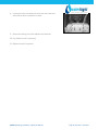
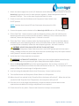
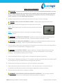
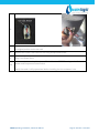
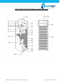
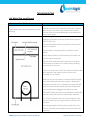
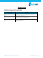
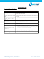
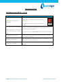
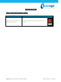
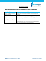
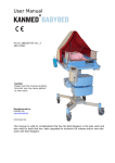
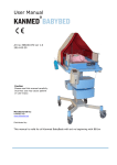
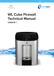
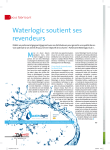
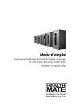
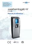
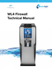
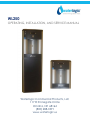
WL250
OPERATING, INSTALLATION, AND SERVICE MANUAL
Waterlogic Commercial Products, LLC
11710 Stonegate Circle
Omaha, NE 68164
(800) 288-1891
www.waterlogic.us
WL250 OPERATING, INSTALLATION, AND SERVICE MANUAL
Congratulations on your choice of the Waterlogic WL250 water treatment system. The WL250
model dispenses cold, and hot. Every WL250 includes:
Bio-Cote Anti-Microbial Protection
Advanced In-Tank Ultraviolet (UV) Purification
The Waterlogic WL250 provides exceptional quality and great tasting water with every use.
TABLE OF CONTENTS
•
•
•
•
•
•
•
•
•
•
•
•
•
•
•
•
•
•
•
•
•
•
Features and Benefits ................................................................. 3
Certifications ............................................................................... 4
Introduction and Safety Alert Symbols ....................................... 5
Safety Precautions ...................................................................... 6
Model and Part Designations...................................................... 7
Specifications .............................................................................. 7
Operating Instructions ................................................................ 8
Hot Tank Principles of Operation................................................ 9
Flow Diagrams........................................................................... 10
Pre-Installation Procedures ...................................................... 12
Draining Procedures.................................................................. 16
Installation Procedures ............................................................. 20
Service Requirements ............................................................... 22
Replacement Components ....................................................... 23
Hot Tank Descaling Instructions ............................................... 24
Resetting the Overload or High Limit Safety ............................ 26
Layout Drawings and Part Lists…………………… ........................... 28
Main Parts Drawings and Parts Lists ......................................... 31
Wetted Parts Drawing and Parts List ....................................... 37
Electrical Diagrams.................................................................... 38
Fault Codes and Troubleshooting ............................................. 40
Warranty .................................................................................. 60
WL250 Operating, Installation, and Service Manual
Page 2 - Revision: 5-14-2015
WL250 FEATURES AND BENEFITS
Cold and Hot Water
Counter Top and Tower Models come standard with Cold and Hot Selections to meet a wide range of
customer demands. The Tower Model is also available in Cold Only Water Version.
High Volume Storage and Water Capacity
Tower Model has 4 liters of Cold Water Capacity and 1.6 Liters of Hot Water Capacity.
Counter Top has 2 liters of Cold Water Capacity and 1.6 Liters of Hot Water Capacity.
BioCote®Anti-Microbial Protection
Plastic surfaces surrounding dispensing areas and drip tray are infused with an
exclusive silver additive called BioCote®. Silver is a natural anti-microbial that
inhibits the growth of microorganisms providing additional surface protection.
Large Dispense Area with Recessed Faucet
8.5 inch dispense height with BioCote® recessed faucet to protect from cross-contamination.
Leak Detection
Counter Top Model is supplied with a Sensor in the Leak Tray that halts water supply to prevent
overflow and sounds alarm to reduce accident potential.
Child Safeguard
WL250 requires Hot Water selection followed by main dispense for Hot Water, and defaults back to
cold selection after 3 seconds of inactivity to prevent accidental dispensing of hot water.
In-Tank UV Purification
Industry leading In-Tank UV Purification prevents the growth of bio-film within the Stainless Steel
Cold Tank.
Auxiliary Port
Auxiliary Port to feed Coffee Machines or other Appliances on Counter Top Models.
WL250 Operating, Installation, and Service Manual
Page 3 - Revision: 5-14-2015
WL250 CERTIFICATIONS
Waterlogic water treatment systems have been tested, and certified to rigorous NSF and UL
Standards. We believe that performance testing and certifications validate Waterlogic as a worldleader in water treatment systems.
WL250 Certifications Include
UL399 – Certified Drinking Water Cooler
Intertek Labs (ETL) Certified the WL250 to ANSI/UL 399 Standard for Drinking Water
Coolers.
BPA Free - Waterlogic tests for BPA and declares that all of its products are Bisphenol-A
FREE and contain no harmful BPA plastics.
NSF/ANSI-61 – Certified Drinking Water System Components
The WL-250 has been tested and certified by The Water Quality Association (WQA) to
NSF/ANSI-61, Section 9.
Waterlogic manufacturing is certified to ISO 9001 – Quality Management
Systems (certified by Moody International). ISO 9001 is the
internationally accepted standard for well managed organizations that
have adopted the key quality management principles to its operations to
bring consistent quality products and a culture of continuous
improvement.
Safe Drinking Water Act
Waterlogic water treatment systems conform to the Safe Drinking Water Act (SWDA) “lead-free”
amendment effective January 4, 2014.
WL250 Operating, Installation, and Service Manual
Page 4 - Revision: 5-14-2015
INTRODUCTION
Carefully read and follow all instructions to ensure proper and efficient operation of your WL250.
Contact Waterlogic or an Authorized Waterlogic Dealer if you have any questions.
Waterlogic and Authorized Waterlogic Dealers employ trained service personnel who are
experienced in the installation, function and repair of Waterlogic equipment. This publication is
written for use by these qualified individuals. Waterlogic encourages users to learn about products,
however, we believe that product knowledge and service is best obtained by consulting Waterlogic
or an Authorized Waterlogic Dealer.
Waterlogic water treatment systems should be combined with selected water treatment
components to create a system specifically tailored for each application by trained and qualified
personnel.
Products manufactured and marketed by Waterlogic and its affiliates are protected by patents
issued or pending in the United States and other countries.
Waterlogic reserves the right to change the specifications referred to in this literature at any time,
without prior notice. Changes or modifications not expressly approved by Waterlogic could void the
warranty and user’s authority to operate the equipment.
SAFETY ALERT SYMBOLS
Read and follow all safety information carefully. The signal words used in this manual are selected as
shown below and based on an assessment of the degree of potential injury or damage (severe or
minor) and the occurrence of injury (definitely occurs or has the potential to occur) when the
warning is ignored:
DANGER!
Indicates a situation which, when not avoided, results in death or severe injury.
WARNING!
Indicates a situation which, when not avoided, has the potential to result in death or severe
injury; and/or severe property damage.
CAUTION!
Indicates a situation which, when not avoided, results or has the potential to result in minor
injury; and/or minor property damage.
WL250 Operating, Installation, and Service Manual
Page 5 - Revision: 5-14-2015
SAFETY PRECAUTIONS
Basic safety precautions should be followed, including the following:
DANGER! If incorrectly installed, operated or maintained, this product can cause death or
severe injury. Those who install, operate, or maintain this product should be trained in its proper use,
warned of its dangers, and should read the entire manual before attempting to install, operate, or
maintain this product.
WARNING! Unit is to be used for its intended purpose as described in this manual, and
untrained individuals who use this manual assume the risk of any resulting property damage or
personal injury.
WARNING! HOT WATER. Unit produces Hot Water up to 188oF. Water above 125oF can cause
severe burns or scalding. Keep unauthorized people and children away from the unit to avoid
accidental dispensing of hot water. Children should not use without supervision.
DANGER! ELECTRICAL SHOCK HAZARD. Always unplug from power supply prior to servicing
equipment to prevent electrical shock.
WARNING! This system to be used for water only and is not intended for use where water is
microbiologically unsafe or with water of unknown quality without adequate disinfection before or
after the system. The system is designed for the supplemental bactericidal treatment of either
treated and disinfected public drinking water, or other drinking water, which has been tested and
deemed acceptable for human consumption by the state or local health agency having jurisdiction.
The system is designed to reduce normally occurring non-pathogenic or nuisance microorganisms
only. System is not intended for treatment of contaminated water.
WARNING! Dispenser Could Tip or Fall causing serious injury. Always install unit on a firm, flat,
and level surface and secure the WL250 to the base cabinet with the screw provided to lock the
components together. Never place heavy items on top of unit and never climb, stand, or hang on unit
or storage cabinet to prevent injury and damage.
CAUTION! INDOOR USE ONLY. Do not install outdoors or where unit is in direct sunlight. Do not
install where ambient temperature goes below 50F or above 97F. Avoid high humidity and moisture.
Product life and performance will be impacted and warranty could be voided.
WL250 Operating, Installation, and Service Manual
Page 6 - Revision: 5-14-2015
MODEL/PART DESIGNATIONS
BRAND NAME
WL250 Counter Top
WL250 Tower
WL250 Tower – Cold Only
DESCRIPTION
Waterlogic WL250 Counter Top - Cold and Hot
MODEL PART NUMBER
12-CHCMU3
F-6002-M-HC-UT-CS-INN
Waterlogic WL250 Tower - Cold and Hot
12-CHCU3
F-6002-FS-HC-UT-CS-INN
Waterlogic WL250 Tower - Cold
12-CCU3
F-6002-FS-C-UT-CS-INN
SPECIFICATIONS
ITEM
WL250 Counter Top
WL250 Tower
Water Connection
¼” Quick Connect
Cold Water Temperature
Cold Water Temperature – Factory Set Point 41° - 5°C
(Adjustable) 34° - 54° F. (1.1° - 12.2°C)
Hot Water Temperature
189° F (87°C)
Hot Water Manual Reset
Overload
Recommended Service
Pressure
221° F (105°C)
40-60 psi (275-414 kPa) – Use Pressure Regulator
Maximum Service Pressure 100 psi (689 kPa) – Use Pressure Regulator
Rated Service Flow
0.5 gallons per minute (1.89 Lpm)
Environmental Temperature 35° - 100°F (2° - 37°C)
UV Lamp
4 Watts
8 Watts
Heater
500 W
Refrigerant Gas
R134a, 40g, 1.41 ounces
R134a Pressures
High (230 psi), Low (90 psi)
R134a, 65g, 2.29 ounces
SHIPPING SPECIFICATIONS
ITEM
Width/Depth/Height
Weight (dry)
WL250 Counter Top
#
13.5” x 14.5” x 17.75” (34cm x 37cm x
45cm)
42 pounds (19.5 kg)
WL250 Tower
13.5” x 14.5 x 40.5” (34cm x 41cm x
103cm)
58 pounds (26.5 kg)
ELECTRICAL SPECIFICATIONS
ELECTRICAL SUPPLY
120V/60Hz, 1PH
15 Amp Service
POWER (approximate)
AMP DRAW (approximate)
Heater
504
4.2 Amps
Compressor
216
1.8 Amps
UV Lamp System
18
0.15 Amps
WL250 TOTAL
738
6.15 Amps
COMPONENT
#WL250 Counter Top is 17.75 in. tall and may not fit between countertops and cabinets - Check installation to ensure adequate clearance.
WL250 Operating, Installation, and Service Manual
Page 7 - Revision: 5-14-2015
OPERATING INSTRUCTIONS
Cold Water
Select
Hot Water
Select
Dispensing Button
The above picture shows front LCD display and control panel for the Waterlogic WL250.
For Cold Water:
Press Cold Water Select Button followed by the Dispensing Button (within 3
seconds).
For Hot Water:
Press Hot Water Select Button followed by the Dispensing Button (within 3
seconds).
NOTE: Default selection mode is Cold Water. Selection will return to default after 3 seconds of
inactivity.
NOTE: Selection indication light will turn red when the Hot Water Select button is pressed, and will
switch back to the default green within 3 seconds after dispensing the hot water.
Selection Indicator Light
WL250 Operating, Installation, and Service Manual
Page 8 - Revision: 5-14-2015
HOT TANK PRINCIPLES OF OPERATION
All Waterlogic Hot Tanks have a built in Vent or
Expansion Chamber in the top of the tank except for
WL270 (GF) units.
The Vent Chamber allows for expansion of the water
when it is heated.
The chambers are separated by a welded-in tank
baffle.
Water always flows into the bottom of the tank and
out the top to the faucet.
The hot tank outlet tube has a restrictor in its base.
This ensures the reservoir is always full by allowing
more water in than out.
There is a small hole in the side of the tank outlet tube
that allows air and water to pass into the vent
chamber as it is heated.
Water in the vent chamber is suctioned back through
the outlet tube vent hole when water is dispensed.
Expansion of water as it is heated in the reservoir will
push the water out the faucet when the outlet tube
vent hole becomes plugged with debris or scale.
The small Outlet Vent Hole is susceptible to scale build
up and is a key indicator that descaling is required.
It is critical to descale the hot tank through the vent
line and outlet line on a regular basis to prevent this
problem.
Descaling through the inlet and/or outlet lines only
will not clean the vent chamber and outlet vent hole
properly.
WL250 Operating, Installation, and Service Manual
Page 9 - Revision: 5-14-2015
WL250 COUNTER TOP WATER FLOW DIAGRAM
WL250 Operating, Installation, and Service Manual
Page 10 - Revision: 5-14-2015
WL250 TOWER WATER FLOW DIAGRAM
Recommended Filtration
WL250 Operating, Installation, and Service Manual
Page 11 - Revision: 5-14-2015
PRE-INSTALLATION PROCEDURES
DANGER! ELECTRICAL SHOCK HAZARD.
Only qualified personnel who have read and understand this entire manual should attempt to
install, or service this unit, failure to do so could result in death or serious injury. DO NOT plug
into an electrical supply until specifically instructed.
WARNING! ALWAYS SANITIZE BEFORE USE.
Sanitize before use to eliminate any potential microbiological contaminates.
Materials Needed:
• Personal Protective Equipment. Rubber or Nitrile Safety Gloves and Protective Eyewear
• Phillips Screwdriver
• Temperature Gage
• Water Pitcher or Container to collect water from the faucet
• 5 gallon container or drain basin
• Sanitizer - Household Bleach (5.25% Sodium Hypochlorite) or Citric Acid Based Cleaner
• ¼” Plastic Tubing, at least 4 feet in length, and assorted ¼” quick connect fittings
• TDS Meter and Test Strips for measuring chlorine - Optional
1. Unpack the Waterlogic WL250 and check exterior for damage.
Flush Filters
CAUTION! FILTER FLUSH REQUIRED.
WL250’s are not supplied with filters. Filters should be configured to optimize your
system…Filters need to be configured and specified to do the job given the local water conditions,
usage, maintenance schedule, and placement restrictions.
In order for our filters to perform as represented and to provide the best quality water possible, it
is essential that filters be replaced periodically. The frequency of filter changes depends upon your
water quality and your water usage. For example, if there is a lot of sediment and/or particles in
your water, then you will have to change your filters more frequently than a location with little to
no sediment. Be sure to replace your filters whenever you notice a decline in the performance,
whether it is a drop in flow rate and/or pressure or an unusual taste in the water.
2. Flush thoroughly per filter manufacturers’ recommendation with fresh water to drain.
3. Once flushed, install the filters. Following the flow direction on the filter.
NOTE: Filters should not be flushed prior to 24 hours before installation to limit Microbial
Growth.
WL250 Operating, Installation, and Service Manual
Page 12 - Revision: 5-14-2015
Sanitizing
Sanitize using a Household Bleach (5.25% Sodium Hypochlorite solution) or other approved
cleaner throughout the cold and sparkling water circuits. Follow all instructions on the sanitizer
and flush with fresh water through the faucet until odor and taste is acceptable.
WARNING! USE PROPER PERSONAL PROTECTIVE EQUIPMENT
Always ensure proper ventilation and use proper personal protective equipment such as gloves
and eye protection when using chemicals. Refer to Material Safety Data Sheet for specific
requirements of each chemical product. Take all necessary precautions to prevent sanitizer from
contacting eyes, clothing, and any other surfaces in could damage (carpets).
4. Disconnect the UV Lamp wiring harness and carefully remove the UV Lamp from the quartz
sleeve.
CAUTION! UV SYSTEM IS FRAGILE. Never handle the UV System
with bare hands. UV Lamp and quartz sleeve must be free of oils
contaminants to ensure proper operation.
and
5. Unscrew cold tank/quartz sleeve retaining cap and remove the
quartz sleeve. This will require top cover to be removed to access properly and facilitate
removal.
6. Mix ½ gallon of sanitizer per directions or use Bleach Solution (1 teaspoon = 1/6 oz. = 5 ml = ½ cap
full) of household bleach (Sodium Hypochlorite 5 - 10% Concentration) with 1/2 gallon of water.
Always ensure sanitizer is compatible with stainless steel and acetyl plastic.
7. Pour sanitizer solution into cold tank thru funnel or spout. You may add concentrated sanitizer
(½ cap bleach) directly into empty cold tank instead of premixing.
8. Inspect and clean quartz sleeve and O-ring. Reinstall the quartz sleeve and quartz sleeve
retaining nut. Tighten firmly to ensure proper seal. Over-tightening can cause damage.
CAUTION! DO NOT INSTALL THE UV LAMP AT THIS TIME
The UV will interact with the sanitizer and could potentially cause taste.
9. Connect 40-60 psi regulated, potable water supply to the water inlet bulkhead fitting located on
the back of the unit. Turn on water supply and check for leaks.
DANGER! ELECTRICAL SHOCK HAZARD.
Do not plug in unit unless qualified. Only qualified personnel who have read and understand this
entire manual should attempt to install or service this unit.
WL250 Operating, Installation, and Service Manual
Page 13 - Revision: 5-14-2015
10. Connect WL250 to power.
CAUTION! NEVER TURN ON HEATER BEFORE FILLING HOT TANK.
Red Heater and Compressor Power Switch must be in the O=OFF
position while the hot tank is empty. Damage could occur within one
minute and the overload (high limit) will require manual reset if heater
is turned on with an empty hot tank.
Fill the Cold Circuit with Sanitizer
11. Depress the main dispensing button on the front control panel until cold water/sanitizing solution
comes out the faucet. NOTE: Container and drain basin will be required to catch the water from
the faucet.
WARNING! Use Personal Protective Equipment. Gloves and Eye Protection Required. The first
2 or 3 gallons of water will contain concentrated sanitizer. Use extreme care!
Flushing the Sanitizer from the Machine
12. Place a pitcher, catch basin, or other container under the faucet of the WL250.
13. Flush the Cold Tank. Run several gallons of water through the faucet by dispensing cold water to
dilute and remove the sanitizer from the cold circuit. You can use chlorine test strips to evaluate
the water.
14. Once the sanitizer odor/taste has been flushed out of the cold side of the machine the
sanitization process for the Cold Circuit is complete.
Fill the Hot Tank
15. Press the Hot Water Select Button, followed by the main dispensing button to fill the hot tank.
Water will dispense from the faucet once the hot tank is full. Flush until water is clear.
WARNING! HOT CIRCUIT IS NOT SANITIZED.
Water in the hot circuit is not sanitary until the temperature exceeds 171oF for at least 5 minutes.
UV System Functional Test
WARNING! ULTRAVIOLET RADIATION. Protect your skin and eyes against ultraviolet rays.
Never look directly at an operating UV light. Disconnect wiring before removing.
16. Reinstall the UV Lamp and connect the wiring.
17. Dim or shield the overhead lights and peer into the machine, on top of the cold tank, at the UV
connector and retaining cap. The blue glow indicates that the lamp is lit.
WL250 Operating, Installation, and Service Manual
Page 14 - Revision: 5-14-2015
Compressor Test
18. Switch Red Compressor / Heater to I=ON position. Always ensure tanks are full of
water before turning on the heater or the overload (high limit) will open and
require manual reset. If the wire condenser at back of the unit is warm, the
refrigeration system is working.
19. Once the machine reaches its target temperature, the compressor will shut off. Draw a glass of
cold water and verify it is has been chilled to proper temperature.
Heater Test
20. Always ensure tanks are full of water before turning on the heater or the overload (high limit) will
open and require manual reset. It will take the heater approximately 10 minutes to heat the
water from ambient 75°F to the factory set point of 185°F. Dispense a cup of hot water to ensure
the temperature/odor/taste is acceptable.
WARNING! VERY HOT WATER CAN BURN OR SCALD.
Hot water should be dispensed carefully into insulated container to avoid injury.
WL250 Operating, Installation, and Service Manual
Page 15 - Revision: 5-14-2015
WL250 COUNTER TOP DRAINING INSTRUCTIONS
Draining Notes
Drain the WL250 for transportation.
WARNING! STORE UNIT EMPTY. ALWAYS SANITIZE BEFORE REUSE.
The unit must be completely drained and sealed before storing to avoid stagnation and reduce
microbial growth).
Prior to draining the hot tank, turn off the Red Heater and Compressor Power Switch, and
dispense 2 liters of hot water from the machine. As hot water is dispensed from the faucet of the
unit, colder water will be introduced into the hot tank. Since the Red Heater and Compressor
Power Switch is turned off, the heater will not energize and heat the incoming tap water.
Following this precaution prevents exposing personnel and equipment (drains, catch basin, etc.)
to scalding hot water.
Disable Cold and Hot Tanks
1. Turn off the Red Heater and Compressor Power Switch to disable the heater and compressor.
2. Dispense 2 liters of water through the hot tank to cool the water temperature in the hot tank and
avoid burns.
WARNING! VERY HOT WATER CAN BURN OR SCALD.
Hot water should be dispensed carefully into insulated container to avoid injury.
Turn off Water Supply and Bleed Water Pressure
3.
4.
5.
6.
Isolate the unit from feed water by turning off the supply.
Dispense cold still water to relieve any pressure built up in the system.
Remove the water supply line from the inlet line bulkhead fitting at back of machine.
Install dust cap or plug into water supply line bulkhead fitting.
Drain the Cold Water Tank and Circuit
7. Remove top cover.
WL250 Operating, Installation, and Service Manual
Page 16 - Revision: 5-14-2015
8. Remove front panel. Remove 2 Phillip screws
securing front panel. Unseat faucet assembly
from panel. Unclip wires from PCB.
9. Disconnect tubing from inlet elbows on both
solenoids and allow water to drain.
10. Reconnect tubing into inlet elbows.
11. Dry inside of unit.
12. Replace front panel.
WL250 Operating, Installation, and Service Manual
Page 17 - Revision: 5-14-2015
WL250 TOWER DRAINING INSTRUCTIONS
Draining Notes
Drain the WL250 for transportation.
WARNING! STORE UNIT EMPTY. ALWAYS SANITIZE BEFORE REUSE.
The unit must be completely drained and sealed before storing to avoid stagnation and reduce
microbial growth).
Prior to draining the hot tank, turn off the Red Heater and Compressor Power Switch, and
dispense 2 liters of hot water from the machine. As hot water is dispensed from the faucet of the
unit, colder water will be introduced into the hot tank. Since the red power switch is turned off,
the heater will not energize and heat the incoming tap water. Following this precaution prevents
exposing personnel and equipment (drains, catch basin, etc.) to scalding hot water.
Disable Cold and Hot Tanks
1. Turn off the Red Heater and Compressor Power Switch to disable the heater and compressor.
2. Dispense 2 liters of water through the hot tank to cool the water temperature in the hot tank and
avoid burns.
WARNING! VERY HOT WATER CAN BURN OR SCALD.
Hot water should be dispensed carefully into insulated container to avoid injury.
Turn off Water Supply and Bleed Water Pressure
3.
4.
5.
6.
Isolate the unit from feed water by turning off the supply.
Dispense cold still water to relieve any pressure built up in the system.
Remove the water supply line from the inlet line bulkhead fitting at back of machine.
Install dust cap or plug into water supply line bulkhead fitting.
Drain the Cold Water Tank and Circuit
7. Remove lower front panel to access tank feed lines.
WL250 Operating, Installation, and Service Manual
Page 18 - Revision: 5-14-2015
8. Disconnect tank line feed lines from hot and cold inlet
solenoids to drain into basin or catch.
9. Reconnect tubing into inlet elbows once drained.
10. Dry inside of unit if necessary.
11. Replace lower front panel.
WL250 Operating, Installation, and Service Manual
Page 19 - Revision: 5-14-2015
INSTALLATION PROCEDURES
Safety and Installation Guidelines
Ensure all Local, State, and Federal Laws and Codes including health and safety guidelines are met
when installing Waterlogic Equipment. Only qualified service technicians should attempt
installation and service of Waterlogic Equipment.
WARNING! ELECTRICAL SHOCK HAZARD. Always unplug (isolate from power supply) to prevent
electrical shock except where electrical tests are specified.
WARNING! IMPROPER SUPPLY OR CONNECTION CAN RESULT IS RISK OF SHOCK.
Connect to a 15 amp 120V 60Hz properly grounded outlet (GFI is recommended). Ensure polarity is
correct and always use a 3-prong outlet. Consult a qualified electrician if you have any questions.
WARNING! USE ONLY Waterlogic SUPPLIED POWER CORD. Locate system within 5 feet of
power supply. Never use an extension cord or adapter. Do not use a damaged power cord or plug.
Keep power cord out of heavy traffic areas and away from heat sources. Do not, under any
circumstances, remove ground prong or alter the power cord. Never pull the power plug from the
outlet with a wet hand or allow the plug to get wet. Failure to use the supplied power cord will void
UL Certification and Warranty.
CAUTION! INDOOR USE ONLY. Never expose to direct sunlight, heat sources, or ambient air
temperature above 100°F (37°C) or below 35°F (2°C). Install indoors and keep unit away from
excessive humidity. Never expose to freezing temperatures. Ensure there is adequate clearance
around the unit to allow refrigeration system condenser to dissipate heat. Warmer environments
require more clearance around the unit. Minimum clearance around all surfaces of the machine is 2inches. Installs where the ambient temperature exceed 80F, require a minimum of 4-inches clearance
for proper heat dissipation and efficient operation.
CAUTION! USE A WATER PRESSURE REGULATOR. Waterlogic will not be responsible for injury or
damage caused by excessive water pressure. Operating pressure must be 40 psi to 60 psi. Be aware
any of potential pressure surges caused by building/municipal pumping stations.
CAUTION! USE UV STABILIZED SUPPLY LINES. Feed the unit with a potable ambient or cold
water supply only. Feed water over 100° F (37°C) can damage the treatment components. Water
block devices and external leak detectors are strongly recommended. Locate the unit as close to the
water supply and the electrical connections as possible.
WARNING! STORE AND TRANSPORT UNIT EMPTY. ALWAYS SANITIZE BEFORE USE.
The unit must be completely drained and sealed before storing to avoid stagnation and reduce
microbiological contamination (potential bacterial growth). Sanitize before use to eliminate any
potential microbiological contaminates
Pre-installation and sanitization procedures as prescribed in this manual must be performed before
installing the WL250.
Always install indoors and place the Waterlogic WL250 on a firm, flat and stable surface.
WL250 Operating, Installation, and Service Manual
Page 20 - Revision: 5-14-2015
1. Attach the water supply line to the 1/4” feed water inlet bulkhead fitting on the back of the unit.
Waterlogic requires the use of a water pressure regulator. Water feed pressure must be
between 40-60 psi. Turn on the water supply and check for leaks.
2. Check to ensure that the Red Heater and Compressor Power Switch is the
O=OFF position.
NOTE: Switches have internal LED that illuminates when placed in I=ON
position.
3. Connect the power cord to the back of the Waterlogic WL250 and to a 120 Volt supply.
4. Fill the Cold Tank. Hold a container under the dispensing faucet, press and hold the main
dispensing button until a continuous flow of water is obtained. Once a continuous flow is
obtained, release the dispensing button. Cold tank is now full.
5. Fill the Hot Tank. Hold a container under the dispensing faucet. Press the Hot Select Button
followed by the main dispensing button until a continuous flow of water is obtained. Once a
continuous flow is obtained, release the main dispensing button. Hot tank is now full.
CAUTION! NEVER TURN ON HEATER BEFORE FILLING HOT TANK.
Red Heater and Compressor Power Switch must be in the O=OFF position while the hot tank is
empty. Damage could occur within one minute and the overload (high limit) will require manual
reset if heater is turned on with an empty hot tank.
6. Verify that the UV lamp operates as expected.
WARNING! ULTRAVIOLET RADIATION. Protect your skin and eyes against ultraviolet rays.
Never look directly at an operating UV light. Always disconnect before removal.
7. Move the Waterlogic WL250 into its final operating position. Be sure that a minimum of 2”
clearance is maintained around both the sides and the back of the unit. This is important to allow
proper airflow and heat exchange of refrigeration system.
8. Level unit using the adjustable feet to level if necessary. Never install on incline.
9. Turn the Red Heater and Compressor Power Switch to I=ON position.
10. When the unit has reached its Hot Temp Set Point, the heater will cycle off. When the unit has
reached its Cold Temp Set Point Temperature, the compressor will cycle off.
11. Once the unit is at the target temperature(s), sample the water to ensure water meets
expectations and additional rinsing or adjustment is not required.
12. Check the unit for any leaks. External Leak Protection is always recommended.
WL250 Operating, Installation, and Service Manual
Page 21 - Revision: 5-14-2015
SERVICE REQUIREMENTS
WARNING! Read and understand the contents of this manual before attempting to service
WL250. Failure to follow the instructions in this manual could result in death, serious personal
injury, or severe property damage. Only trained and qualified technicians should attempt to
install, maintain, or service Waterlogic Equipment.
1. Visually inspect all electrical and water connections for signs of wear or damage.
DANGER! HIGH VOLTAGE ELECTRICAL HAZARD. Unplug before inspection and service.
2. Waterlogic recommends changing the UV Lamp every 12 months.
NOTE: When replacing the UV lamp the wiring harness must also be
replaced.
NOTE: The Glow Starter shown to the right, may appear blackened
which is normal.
WARNING! ULTRAVIOLET RADIATION. Protect your skin and eyes against ultraviolet rays.
Never look directly at an operating UV light. Disconnect before removing UV Lamp.
CAUTION! UV LAMPS ARE HAZARDOUS. Lamps are considered Hazardous Waste and must
be disposed of accordingly. Refer to Product MSDS sheet for details.
3. Clean the quartz sleeve that surrounds the UV lamp with a non-abrasive cloth, descaling solution,
or ultrasonic bath if needed when changing UV lamps.
CAUTION! UV SYSTEM IS FRAGILE. Never handle the UV lamp or Quartz Sleeve with bare
hands. UV Lamp and quartz sleeve must be free of oils and contaminants to ensure proper
operation. Use a soft non-abrasive cloth to clean.
4. Inspect the Quartz Sleeve O-ring for wear or damage and replace as necessary.
5. Ensure there is adequate (minimum of 2”) clearance around the unit and clean the condenser grill
and compressor fan to provide efficient cooling system operation.
6. Sanitize the cold tank per instructions in the pre-installation procedures.
7. Clean and sanitize external surfaces of the unit. Use soap and water or chemicals that are
compatible with ABS plastic and will not damage or degrade the product surfaces.
8. Remove and clean the Faucet. Replace as needed.
WARNING! SANITIZER MAY CONTAIN HAZARDOUS CHEMICALS. Use of proper personal
protective equipment such as rubber gloves and eye protection is required.
WL250 Operating, Installation, and Service Manual
Page 22 - Revision: 5-14-2015
REPLACEMENT COMPONENTS
Component
UV Light, 4 Watts – Counter
Top
UV Quartz Sleeve – Counter
Top
Part No.
UV Light, 8 Watts - Tower
CT-2083
UV Quartz Sleeve - Tower
CT-2002
Black Quartz Sleeve O-Ring
CT-2006
Hot Tank (87°C - 189°F) –
Counter Top
Hot Tank (87°C - 189°F) Tower
CT-2030
CT-2026
HT-3018-A
HT-3018
Frequency of Replacement
Every 12 months, or as required
WLUSA Part No 12-2350
Clean every 12 months, replace as needed
WLUSA Part No 14-1051
Every 12 months, or as required
WLUSA Part No. – 10-2350
Clean every 12 months, replace as needed
WLUSA Part No. 10-1400
Each time Quartz Sleeve is replaced
WLUSA Part No 10-2500
Replace every 5 years
WLUSA Part No 12-1406
Replace Every 5 Years
WLUSA Part No 12-1405
Replacement parts can be obtained from Waterlogic or an Authorized Waterlogic Dealer.
See Parts Layouts, Drawings, and Lists for additional repair parts.
Hot Tank Service
Hot Tanks (with controls) must be replaced at least every 5 years. Descaling hot tank may be
required on a regular basis depending upon filtration and local water conditions. See Service Section.
NOTE:
At the end of this product’s life, ensure that it is disposed of in an environmentally friendly manner
which is fully compliant with all Federal/State/Local Requirements and Guidelines.
WL250 Operating, Installation, and Service Manual
Page 23 - Revision: 5-14-2015
HOT TANK DESCALING INSTRUCTIONS
The hot tank requires removal of mineral deposits (descaling) on a regular basis. Typically
descaling should take place every 6 to 12 months to preserve the long-term health of your unit.
Use non-toxic cleaner such as ScaleKleen, DEZCAL, 20% Citric Acid Solution, or Undiluted Vinegar
Solution to remove mineral deposits as directed by the manufacturer depending upon filtration
and local water conditions.
Descaling is an important process that removes calcium deposits, or scale, that can build up
inside a tank over time. Calcium and scale is non-toxic but left unattended will hinder your unit’s
performance.
WARNING! PERSONAL PROTECTIVE EQUIPMENT REQUIRED. Always ensure proper
ventilation and use rubber or nitrile gloves and eye protection when using chemicals. Refer to
Material Safety Data Sheet for specific requirements of each product.
CAUTION! STAINLESS STEEL TANK DESCALING.
The hot tank is made from stainless steel. Ensure descaling solution is compatible with stainless
and always flush the unit completely. Dispose in an environmentally safe manner.
Materials Needed:
• Personal Protective Equipment. Rubber or Nitrile Safety Gloves and Protective Eyewear
• Phillips Screwdriver
• Temperature Gauge
• Water Pitcher or Container to collect water from the faucet
• 5 gallon container or drain basin
• Citric Acid Based Cleaner
• ¼” Plastic Tubing, at least 4 feet in length, and assorted ¼” quick connect fittings
• Sanitizing Cartridge
• Food Coloring
1. Put descaler per directions and 3 drops of food coloring into the descaling cartridge.
2. Connect descaling cartridge to the inlet water supply and connect to inlet bulkhead fitting on the
back of the unit. Turn on Water Supply.
3. Select Hot Water and depress the Main Dispensing Button on the Front Control Panel until
descaling solution (colored water) comes out of the faucet. Container and drain basic will be
required to catch water from the faucet.
4. Turn off water supply and remove sanitizing cartridge from inlet water supply. Reconnect water
supply to inlet fitting.
WL250 Operating, Installation, and Service Manual
Page 24 - Revision: 5-14-2015
5. Allow descaling solution to remain in the Hot Tank for 15 minutes (length of time may vary
depending on water conditions).
6. Place a pitcher, catch basin or other container under the faucet of the WL250.
7. Flush the Hot Tank until water runs clear.
8. Once clear Water dispenses from the faucet the Hot Tank has been descaled. Always ensure unit
is performing to the customer’s satisfaction.
WARNING! HOT WATER HAZARD. Unit Produces Very Hot Water and Steam. Always use
insulated and chemically compatible containers and let unit cool down before draining the hot
tank to avoid injury.
CAUTION! MUST REPLACE HOT TANK 5 YEARS. The hot tank and its controls must be
replaced a minimum of every five years to ensure efficient and dependable operation.
WARNING! REINSTALL ALL PANELS AND COVERS. Always reinstall all panels, protective
covers, and fasteners after servicing equipment. Failure to do so could result in severe personal
injury and will void the certifications and warranty of the equipment.
WL250 Operating, Installation, and Service Manual
Page 25 - Revision: 5-14-2015
RESETTING THE OVERLOAD OR HIGH LIMIT SAFETY
1.
Turn off Red Heater and Compressor Power Switch on rear of unit.
2.
Unplug the Power Cord from rear of unit.
3.
Remove the Lower Front Panel of unit by removing the Phillips head screws underneath
the lower front panel.
4.
Locate the protective metal box on the rear of the hot
tank. As you look through the condenser coils on the
rear of the unit, you will see the hot tank located on the
right hand side.
From the front of the Water Treatment System, reach
up behind the hot tank and take hold of the protective
metal box covering the thermostat and overload on the
hot tank.
5.
There are nuts that secure the metal box to the hot
tank. However the nuts are loose enough to allow you
to remove the metal box.
If the nuts on the metal box are too tight, loosen the
nuts securing the hot tank to the upper base of the unit
and lower the hot tank so you can remove the metal
box.
For demonstrative purposes, photos below have
lowered the hot tank from the unit.
WL250 Operating, Installation, and Service Manual
Page 26 - Revision: 5-14-2015
Press the reset button
6.
7.
Reattach the metal box by depressing the top flap of the metal box so it snaps back into
its original position on the hot tank.
8.
Replace the Lower Front Panel on unit using Phillips head screws.
9.
Plug in the Power Cord.
10
Make sure the hot and cold tanks are filled with water BEFORE turning on the Red
Heater and Compressor Power Switch
Verify the cooler is fully operational before installing it at the customers’ site.
WL250 Operating, Installation, and Service Manual
Page 27 - Revision: 5-14-2015
WL250 COUNTER TOP LAYOUT DRAWING with PART NUMBERS
No
Part No
Description
WLUSA Part No.
1
PL-1249CN
Top Cover Charcoal with BioCote®
12-8060
2
LP-7084
Button Label
12-8057
3
PL-1153
Silicon Button Key Mat
12-8056
4
PL-1147-B
Front Hatch Panel Charcoal - UV Inside Logo with
BioCote®
12-8051
5
PL-1146
Drip Tray Insert Panel
12-8050
6
PL-1152
Drip Tray Grill with BioCote®
12-8150
7
PL-1156
Drip Tray Body with Waterlogic Logo (Assembly) with
BioCote®
12-8055
8
ST-8140
4mm x 10mm Screw
NA
9
EL-5004
Red Heater and Compressor Switch
10-3008
10
EL-5053
Fuse Holder Assembly and Fuse
EL-5053
10a
NA
Fuse (15A, 110V)
NA
11
ST-8216
Back Panel
12-8061
12
EL-5016
Power Line Noise Filter, EMI Filter
10-4013
13
PU-4011
JG Bulkhead Connector Union 1/4" * 1/4" (JG part #
PI1208S)
NA
14
ST-8151
Bottom Base Panel
12-3170
15
PU-4028
JG Bulkhead Connector Union 1/4" * 1/4" (JG part #
PI1208S)
10-3067
16
ST-8245
Side Panel
12-8062
17
CT-2016
Cold Water Thermostat
12-1101
WL250 Operating, Installation, and Service Manual
Page 28 - Revision: 5-14-2015
WL250 TOWER LAYOUT DRAWING with PART NUMBERS
WL250 Operating, Installation, and Service Manual
Page 29 - Revision: 5-14-2015
WL250 TOWER LAYOUT DRAWING with PART NUMBERS
No
Part No
Description
WLUSA
Part No.
Hot and
Cold
Cold
Only
1
PL-1150
Top Cover with BioCote®
12-8054
X
X
2
PL-1147-B
Front Hatch Panel Charcoal with UV Logo
- BioCote®
12-8051
X
X
3
LP-7084
Button Label Hot and Cold
12-8057
X
3
LP-7085
Button Label Cold Only
12-8610
4
EN-6085
PCB LED Hot and Cold
12-8103
4
EN-6086
PCB LED Cold Only
12-8615
5
PL-1153
5
PL-1100
6
PL-1011-A
Faucet Nipple with BioCote®
10-3048
X
7
PL-1146
Front Panel for Drip Tray Insert
12-8050
X
X
8
PL-1156
Drip Tray Body Charcoal with BioCote®
12-8055
X
X
9
PL-1149
Front Down Insert Panel
12-8053
X
X
10
PL-1148
Front Down Panel
12-8052
X
X
11
ST-8135
Back Panel Silver
12-8002
X
X
12
CT-2016
Cold Water Thermostat
12-1101
X
X
13
EL-5050
Power Transformer UV 120V/60Hz
12-3245
X
X
14
ST-8136
Upper Front Shelf
12-8003
X
X
15
CT-2029
12-4000
X
X
16
HT-3018
12-1405
X
18
PU-4016
Solenoid Valve DC24V 1000mm
12-1500
X
X
19
ST-8138
Filter Bracket
12-8005
X
X
20
N/A
Filter
N/A
X
X
21
CO-9001-A
Compressor
10-2200
X
X
22
ST-8167CN
Rubber Feet
11-2065
X
X
23
ST-8137
Down Base
12-8004
X
X
24
EL-5004
Red Heater and Compressor Switch
10-3008
X
X
25
EL-5016
Socket with EMI Filter
10-4013
X
X
26
EL-5053
Fuse Holder and Fuse 110V/15A
EL-5053
X
X
27
PU-4011
JG Bulkhead Connector Union 1/4" *
1/4" (JG part # PI1208S)
10-3067
X
Silicon Button Keymat Hot and Cold with
BioCote®
Silicon Button Keymat Cold Only with
BioCote®
Cold Tank 4 Liter Assembly with UV
Holder
Hot Tank Stainless Steel 1.6 Liter (87°C 189°F)
WL250 Operating, Installation, and Service Manual
12-8056
X
X
X
X
12-8600
X
Page 30 - Revision: 5-14-2015
WL250 COUNTER TOP MAIN PARTS DRAWING
WL250 Operating, Installation, and Service Manual
Page 31 - Revision: 5-14-2015
WL250 COUNTER TOP MAIN PARTS LIST
No
Part No
Description
WLUSA Part No.
1
PL-1249CN
Top Cover Charcoal with BioCote®
12-8060
2
CT-2001-B
UV Lamp Fixing Rubber (Silicon)
10-8085
3
PL-1128
UV Lamp Retaining Threaded Nut
12-1210
4
PU-4016
Solenoid Valve DC24V 500 mm
12-1500
5
EL-5006-A
UV Lamp Ballast with Metal Cover
10-3010
6
ST-8150
Upper Base
12-3165
7
CT-2060
UV Cold Tank Assembly 2 Liter
12-3110
8
ST-8245
Side Panel Right
12-8062
9
PL-1146
Front Panel for Drip Tray Insert
12-8050
10
PL-1298
PCB Cover
12-3160
11
EN-6085-A
PCB
12-3115
12
PL-1153
Silicon Button Key Mat with BioCote®
12-8056
13
PL-1147-B
Front Hatch Panel Charcoal with UV Logo with BioCote®
12-8051
14
LP-7084
Button Label
12-8057
15
PL-1152
Drip Tray Grill with BioCote®
12-8150
16
PL-1156
Drip Tray Body with Waterlogic Logo with BioCote®
12-8055
17
CO-9001-A
Compressor (R134a 1/8 HP) 110V / 60Hz
10-2200
18
PL-1251-CN
Unit Rubber Feet
12-3150
19
NA
Bolt M6*30
NA
20
ST-8151
Lower Base
12-3170
21
PL-1294
Leak Tray
12-3155
22
ST-8207-CN
Leak Containment Tray Clip – Sensor 0.5mm
12-3180
23
ST-8152
Filter Bracket
12-3175
24
ST-8244
Leak System Inlet Solenoid Fixing Bracket
12-3195
25
NA
JG Equal Tee Connector ¼” (P10208S)
NA
26
PU-4016
Solenoid Valve DC24V 500 mm
12-1500
27
NA
JG Equal Elbow Connector ¼” (PI0308S)
NA
28
NA
JG Reducing Elbow Connector 5/16” * ¼” (PI211008S)
NA
29
NA
JG Equal Tee Connector ¼” (P10208S)
NA
30
PU-4007
JG Reducing Elbow Connector 5/16” * ¼” (PI211008S)
13-3055
31
CT-2006
O-Ring – Black Quartz Sleeve
10-2500
32
CT-2026
Quartz Sleeve D152mm for 4W Lamp
14-1051
WL250 Operating, Installation, and Service Manual
Page 32 - Revision: 5-14-2015
33
EL-5003-A
Power Transformer
12-3117
34
HT-3018-A
Hot Tank 1.6 Liter Stainless (87°C - 189°F)
12-1406
34a
HT-3012
Thermal Overload (105°C - 221°F)
12-1360
34b
HT-3013A
Hot Tank Thermostat
12-1303
34c
ST-0045L00-00
Thermostat and Overload Metal Cover
12-6900
35
CO-9031
Wire Condenser
12-3100
36
ST-8245
Side Panel Left
12-8062
37
NA
JG Equal Tee Connector ¼” (PI0208S)
NA
38
NA
Plastic Cap for ¼” Bulkhead Fitting
NA
39
ST-8140
Screw 4*10
NA
40
EL-5016
Socket with EMI Filter
10-4013
41
EL-5053
Fuse Holder and Fuse 110V / 15A
EL-5053
42
EL-5004
Red Heater and Compressor Switch
10-3008
43
CT-2016
Cold Water Thermostat
12-1101
44
ST-8216
Back Panel
12-8061
45
CT-2084
UV Lamp 4W – Philips
12-2350
45a
EL-5048
Wire Harness Set
12-8210
46
PL-1011-A
Faucet Nipple with BioCote®
10-2701
46a
PL-1079-BO
Blue Faucet Nipple, with Stainless Steel Gauze
10-3048
46b
CT-2007
Faucet O-Ring
10-2600
CO-9016
Starter Relay for Compressor
10-3003
CO-9015
Thermal Overload (102°C - 221°F)
10-5018
Not
Shown
Not
Shown
WL250 Operating, Installation, and Service Manual
Page 33 - Revision: 5-14-2015
WL250 TOWER MAIN PARTS DRAWING
WL250 Operating, Installation, and Service Manual
Page 34 - Revision: 5-14-2015
WL250 TOWER MAIN PARTS LIST
NO
Part No
Description
WLUSA Part No
1
ST-8157
Side Panel
12-8000
2
PL-1147-B
Front Upper Panel
12-8051
3
PL-1153
Silicon Button Key Mat
12-8056
4
EN-6085-A
PCB
NA
4a (Not Shown)
LP-7084
Button Label
12-8057
5
PL-1152
Drip Tray Grill BioCote®
12-8150
6
PL-1156
Drip Tray Body with WL Logo
12-8055
7
PL-1146
Front Panel for Drip Tray Insert
12-8050
8
PL-1081-BO
Faucet, White Plastic with SS Inserts
10-2700
8a (Not Shown)
CT-2007
Natural Faucet O-Ring – Silicon White
10-2600
8b (Not Shown)
PL-1079-BO
Blue Faucet Nipple with Stainless Steel Gauze
10-3048
9
PL-1149
Front Lower Insert Panel
12-8053
10
PL-1148
Front Lower Panel
12-8052
11
NA
Sediment Filter, 5 Micron – Recommended
12-2000
12
NA
Carbon Block Filter, 1 Micron – Recommended
12-2001
13
NA
GAC Filter, Taste and Odor Reduction – Recommended
12-2002
14
ST-8138
Filter Bracket
12-8005
15
PU-4016
Solenoid Valve DC24V 1000mm
12-1500
16
PU-4025
Filter Clip, 2 Inch for In-Line Filter
10-3098
16a (Not Shown)
PU-4024
Filter Clip, 2.5 inch for Sediment and Carbon Filters
10-3099
17
PL-1150
Top Cover – Black
12-8054
18
CT-2083
UV Lamp – 8W Assembly
10-2350
18a (Not shown)
NA
UV Lamp Wiring Harness (Included in assembly)
NA
18b (Not Shown)
CT-2001-B
UV Lamp Fixing Rubber
10-3004
19
PL-1128
UV Lamp retaining Threaded Nut
12-1210
20
CT-2006
O-Ring – Black Quartz Sleeve
10-2500
21
CT-2002
Quartz Sleeve for 8W Lamp
10-1400
22
EL-5003-A
Power Transformer UV 120V / 60Hz
12-3117
23
EL-5006-A
UV Lamp Ballast 110V
10-3010
24
ST-8136
Steel Upper Shelf
12-8003
25
ST-0045-L0000
Hot Tank Supplemental Steel Enclosure
12-6900
25a (Not Shown)
HT-3012
Thermal Overload for Hot Tank, Manual Reset
12-1360
25b (Not Shown)
HT-3013A
Hot tank Thermostat
12-1303
26
HT-3018-A
Hot Tank Assembly 1.6 Liter Stainless with Thermostat
Tank (87°C - 189°F)
12-1415
WL250 Operating, Installation, and Service Manual
Page 35 - Revision: 5-14-2015
26a (Not Shown)
ST-8120
Hot Tank Mounting Bracket
12-8006
26b (Not Shown)
EN-6042
Hot Tank Power Wire, Red
12-1102
26c (Not Shown)
EN-6044
Thermal Cutout Wire, Connects Hot Tank Thermostat
to Hot Tank Overload
12-1306
26d (Not Shown)
HT-3007
Hot Tank Fixing Nut
12-1301
26e (Not Shown)
EL-5048
Wire Harness Set
12-8210
26f (Not Shown)
PU-4064
Silicon Tube 5/16” for Hot Water
10-7040
27
HT-3022
Insulation, Hot Tank, Sidewall
12-8007
NA
Insulation, Hot Tank, Top Section
NA
28
CT-2060
UV Cold Tank Assembly 2 Liters
12-3110
29
CO-9011
Insulation, 4 Liter Cold Tank
12-1002
30
NA
Intentionally Left Blank
NA
31
NA
Intentionally Left Blank
NA
32
CO-9008
Filter Dryer
12-1001
33
CO-9001-A
Compressor (R134a 1/8 HP) 110V/60Hz
10-2200
33a (Not Shown)
CO-9016
Starter Relay for Compressor
10-3003
33b (Not Shown)
CO-9015
Thermal Overload for Compressor
10-5018
33c (Not Shown)
EN-6025
Ground Wire – Compressor L320mm
10-7095
34
ST-8137
Lower Steel Shelf
12-8004
35
PL-1251-CN
Unit Rubber Feet
12-3150
36
ST-8157
Silver Side Panel with Handle Hole
12-8000
37
CO-9027
Condenser
12-8102
38
ST-8135
Back Panel
12-8002
39
CT-2016
Cold Water Thermostat
12-1101
40
EL-5004
Red Heater and Compressor Switch
10-3008
40a (Not Shown)
EL-5051
Wire Harness Set
12-8107
40b (Not Shown)
EN-6065
Red Switch Wire with UV Lamp Connector
12-1208
40c (Not Shown)
EN-6064
Black Switch Wire with UV Lamp Connector
12-1209
41 &42
EL-5053
Fuse Holder and Fuse 110V / 15A
EL-5053
43
EL-5001-A
Power Cord – AC USA Molded Black – 120V – 1825 mm
10-3007
44
EL-5016
Power Line Noise Filter, EMI Filter
10-4013
Not Shown
AK-0008-A
UV 3 Minute Timer Board / PCB Hot and Cold
12-8510
Not Shown
AK-0008-C
UV 3 Minute Timer Board / PCB Cold
12-8520
Not Shown
PL-1011-A
Faucet Nipple with BioCote®
10-2701
Not Shown
PL-1013
Blue Faucet Nipple, with Stainless Steel Gauze
10-3048
Not Shown
CT-2007
White Silicon Faucet O-Ring
10-2600
27a (Not Shown)
WL250 Operating, Installation, and Service Manual
Page 36 - Revision: 5-14-2015
WL250 TOWER WETTED PARTS DRAWING AND PARTS LIST
C
D
No
Part No
Description
A
PU-4028
JG Bulkhead Connector Union ¼” * ¼” – PI1208S
10-3067
B
PU-4031
JG LLD PE Tube – Blue OD ¼” – PE-08-BI-1000F-B
NA
C
PU-4008
JG Equal Elbow Connector ¼” – PI0308S
NA
D
PU-4007
JG Reducing Elbow Connector 5/16” * ¼” – PI211008S
NA
E
PU-4014
Blue Hose 8mm
F
NA
JG Equal Tee Connector ¼” – PI0208S
WL250 Operating, Installation, and Service Manual
WLUSA Part No.
10-3062
NA
Page 37 - Revision: 5-14-2015
WL250 COUNTER TOP ELECTRICAL DIAGRAM
DANGER! HIGH VOLTAGE ELECTRICAL HAZARD. PCB (Printed Circuit Board) contains High
Voltage. Only trained and qualified technicians should attempt live testing.
WL250 Operating, Installation, and Service Manual
Page 38 - Revision: 5-14-2015
WL250 TOWER ELECTRICAL DIAGRAM
DANGER! HIGH VOLTAGE ELECTRICAL HAZARD. PCB (Printed Circuit Board) contains High
Voltage. Only trained and qualified technicians should attempt live testing.
WL250 Operating, Installation, and Service Manual
Page 39 - Revision: 5-14-2015
FAULT CODES
FAULT CODE: Red Flashing Light and Audible Alarms are the Leak Detector Alarms for
Counter Top Model
Possible Reason
Water exiting drip tray due to
being full
Leak in WL250 Counter Top
Solution
Empty Drip Tray. Remove Top cover and Front Panel prior to
drying out inside of the unit.
Water is in the bottom of the unit. Open up unit to
determine where the leak is.
Check for source of leak. Dry out inside of unit.
Flashing Red Light
FAULT CODE: No LED Light
Possible Reason
Power Problem
Solution
Check for power disruption.
No LED Light
WL250 Operating, Installation, and Service Manual
Page 40 - Revision: 5-14-2015
TROUBLESHOOTING
Irregular / Intermittent Dispensing
Possible Reason
Too much water pressure.
Recommend 40 to 60 psi for
WL250 to operate properly.
Solution
Check water pressure at the inlet bulkhead with a water
pressure gauge.
Additional method of verification is to turn off water to unit
and press the dispense button. Does the solenoid open
without water pressure to the unit? Listen for solenoid to
activate, not button “click”.
Adjust water pressure to 40-60 psi.
Dispensing button is broken on Check PCB for loose or damaged button. Replace PCB as
PCB
necessary.
WL250 Operating, Installation, and Service Manual
Page 41 - Revision: 5-14-2015
TROUBLESHOOTING
No Water is Dispensing from One Side – Cold or Hot
Possible Reason
Too much water pressure.
Recommend 40 to 60 psi for
WL250 to operate properly.
Solution
Check water pressure at the inlet bulkhead with a water
pressure gage.
Additional method of verification is to turn off water to unit
and press the dispense button. Does the solenoid open
without water pressure to the unit? Listen for solenoid to
activate, not button “click”.
Adjust water pressure to 40-60 psi.
Switch the hot and cold wires on PCB (red and blue
connections).
PCB
Solenoid
If water now dispenses from the opposite side, this is an
indication that there is a PCB problem.
Replace PCB
If both the Water Pressure and PCB have been ruled out,
then it is the Solenoid.
Replace Solenoid.
WL250 Operating, Installation, and Service Manual
Page 42 - Revision: 5-14-2015
TROUBLESHOOTING
Hot Water is not Hot (185° +/- 5° F)
NOTE: The WL250 does NOT have Sleep or Power Saving Mode and the hot water should be a
minimum of 185°F under normal operating conditions.
The Hot temperature set point is 185° F and is controlled by a thermostat on the side of the tank.
There is a resettable overload or high limit safety above the thermostat on the side of the tank that
will trip to prevent damage to the unit if the tank is dry heated (turned on without water in it).
The WL250 does NOT have Extra Hot capability and the maximum hot temperature is 193°F.
It typically takes 10 minutes for the 500W to heat the 1.6 Liter of room temperature (ambient) water
to the 185°F set point.
Possible Reason
No power to heater elements
Loose or improperly
connected wire(s) to the
heating element / hot tank.
Overload Tripped
Overload is a safety feature to
ensure the tank does not
overheat.
Solution
Check that the Red Heater and Compressor
switch is on.
Turn Red Heater and Compressor Switch on.
I = ON
Visually inspect wire leads gong to the hot tank; confirm
proper connections to the heating elements.
Hot tank life is 3-5 years, depending on usage.
*Typically dealers swap out the hot tank at site, take back to
the shop to repair.
Overload will “click” when pushed. The overload is
automatically reset when pressed.
*See Overload Reset Instructions Included in Manual
Turn Power off. Check OHM’s resistance across terminals on
each Thermostat and Overload separately.
Thermostat or overload
“open” on Hot Tank
Good components will indicate a closed circuit or zero
OHM’s on the meter.
Replace components as necessary.
Turn Power off; Drain hot tank; Use multi-meter to check
heater element for approximately 26 OHM’s resistance.
Heating Coil not Working
Hot tank must be empty if you are checking for continuity.
Replace Hot Tank as necessary.
WL250 Operating, Installation, and Service Manual
Page 43 - Revision: 5-14-2015
TROUBLESHOOTING
Hot Water or Steam Coming out of both the Faucet and Vent Hole
Possible Reason
Improper tubing attachment
from the hot tank to faucet or
vice versa.
Solution
Check that the tubing is connected from tank outlets to
correct faucet attachments. Connect tubing to outlets as
needed.
WL250 Operating, Installation, and Service Manual
Page 44 - Revision: 5-14-2015
TROUBLESHOOTING
Hot Water Drip out of Faucet
Possible Reason
Small Outlet Vent Hole susceptible to scale
build up.
Solution
Descale Tank. Descale Instructions are available as a
separate section of this Manual and see the "How to
Descale your Hot Tank” instructional video on the
Partner Area of the new Waterlogic.com website for
more information.
All Waterlogic Hot Tanks have a built in Vent or
Expansion Chamber in the top of the tank except for
WL270 (GF) units.
The Vent Chamber allows for expansion of the water
when it is heated.
The chambers are separated by a welded-in tank
baffle.
Water always flows into the bottom of the tank and
out the top to the faucet.
The hot tank outlet tube has a restrictor in its base.
This ensures the reservoir is always full by allowing
more water in than out.
There is a small hole in the side of the tank outlet tube
that allows air and water to pass into the vent
chamber as it is heated.
Water in the vent chamber is suctioned back through
the outlet tube vent hole when water is dispensed.
Expansion of water as it is heated in the reservoir will
push the water out the faucet when the outlet tube
vent hole becomes plugged with debris or scale.
The small Outlet Vent Hole is susceptible to scale build
up and is a key indicator that descaling is required.
It is critical to descale the hot tank through the vent
line and outlet line on a regular basis to prevent this
problem.
Descaling through the inlet and/or outlet lines only
will not clean the vent chamber and outlet vent hole
properly.
WL250 Operating, Installation, and Service Manual
Page 45 - Revision: 5-14-2015
TROUBLESHOOTING
Hot Water Coming out of Faucet Vent Hole
Possible Reason
Improper tubing attachment
from the tank to faucet or vice
versa.
Solution
Verify tubing is connected properly from tank outlets to
correct faucet attachments.
Hot Tank outlet hole is scaled
over.
Inspect and descale or replace hot tank.
Expansion chamber is not
sealed properly.
Replace the Hot Tank.
WL250 Operating, Installation, and Service Manual
Page 46 - Revision: 5-14-2015
Restricted Flow of Hot Water
Possible Reason
Partially closed water supply
valve to the unit.
TROUBLESHOOTING
Solution
Open water supply valve.
Hot Tank outlet hole is scaled
over.
Remove outlet tube from hot tank to faucet. Add descaler to
hot tank.
Tubing is creased or has a
“kink” in it.
Inspect and replace tubing as necessary.
Faucet nipple screen mesh has
obstruction(s)
Unscrew faucet nipple from faucet and remove any
obstruction(s) from screen mesh.
Exhausted Filter
Replace the Filter
Solenoid connection to the
Display PCB
Solenoid Valve is
Malfunctioning
Turn power off; unplug the unit and visually inspect solenoid
connections into the Display PCB. Verify the soldering points
on connections are secure into the board.
Remove the PCB to inspect the front of the board.
Inspect valve components for proper function. Replace as
necessary.
WL250 Operating, Installation, and Service Manual
Page 47 - Revision: 5-14-2015
TROUBLESHOOTING
Cold Water is not Cold (41° +/- 5° F)
Possible Reason
No power or refrigeration
elements
Tank has run out of cold water.
Solution
Check that the Red Heater and Compressor
switch is on.
Turn Red Heater and Compressor Switch on.
I = ON
Wait for cold tank to chill water to temperature prior to
dispensing more cold water.
Cold tank capacity is 4 liters for
Tower and 2 liters for Counter
A greater capacity of Waterlogic Water Systems is available.
Top.
Cold Water Thermostat
Check continuity of thermostat with multimeter. Replace
thermostat as required.
Refrigerant has run out
Run compressor for at least ten minutes. If condenser is not
warm then refill the refrigerant.
Compressor problem
If compressor is not running, repair or replacement is
needed.
WL250 Operating, Installation, and Service Manual
Page 48 - Revision: 5-14-2015
TROUBLESHOOTING
Steady Drip Out of Faucet
Possible Reason
Debris in Solenoid
Solution
Inspect Solenoid for debris and clean out as needed.
WL250 Operating, Installation, and Service Manual
Page 49 - Revision: 5-14-2015
TROUBLESHOOTING
Dispenses Hot and Cold Water at the Same Time
Possible Reason
Remove top cover.
Solution
Check Hot Solenoid: Dispense cold water and visually inspect
tubing for water flow from both tanks.
Hot or Cold solenoid is stuck
open.
Check Cold Solenoid: Disconnect elbow from outlet of cold
solenoid. Select hot water and dispense (quickly releasing
dispensing button to avoid much water coming out of cold
solenoid.
Replace solenoid as necessary.
WL250 Operating, Installation, and Service Manual
Page 50 - Revision: 5-14-2015
TROUBLESHOOTING
No Cold Water Available
Possible Reason
Solution
Closed Water Supply Valve
Open the Water Supply Valve
Cold Water Solenoid Valve
malfunction
Inspect the valve components for proper functionality.
Red Heater and Compressor
Switch on unit is off.
Turn Red Heater and Compressor Switch on.
I = ON
Loose connection(s) on the
Display PCB
Turn power off; unplug the unit and visually inspect solenoid
connections into the Display PCB. Verify the soldering points
on connections are secure into the board.
Remove the PCB to inspect the front of the board.
Exhausted Filter
Replace filters as needed.
WL250 Operating, Installation, and Service Manual
Page 51 - Revision: 5-14-2015
TROUBLESHOOTING
Water is Not being Heated or Chilled
Possible Reason
Red Heater and Compressor
Switch on unit is off.
Solution
Turn Red Heater and Compressor Switch on.
I = ON
WL250 Operating, Installation, and Service Manual
Page 52 - Revision: 5-14-2015
TROUBLESHOOTING
No Cold or Hot Water Will Dispense from Unit
Possible Reason
Solution
Closed water supply valve
Open the water supply valve.
The unit is not properly
plugged into electrical outlet
Check electrical outlet connection, or for blown circuit
breaker.
Red Heater and Compressor
button on unit is in the off
position
Turn Red Heater and Compressor switch on.
I = ON
15 Amp Fuse Blown
Replace the 15 Amp Fuse as needed.
Water is present in the bottom
tray, causing the leak
detection to trigger.
Remove the top cover and front panel. Tip the unit slightly
to drain, dry bottom tray completely.
*Leak Detection is on Counter
Top model only.
Turn power off; unplug the unit and visually inspect solenoid
Hot and Cold Solenoid
connections into the Display PCB. Verify the soldering points
connections into the Displace
on connections are secure into the board.
PCB are loose.
Remove the PCB to inspect the front of the board.
Exhausted Filter
Replace filters as needed.
WL250 Operating, Installation, and Service Manual
Page 53 - Revision: 5-14-2015
TROUBLESHOOTING
Cold Water Dispenses from Faucet and Vent Outlet Simultaneously
Possible Reason
Improper tubing attachment
from the tank to faucet or vice
versa
Scale has formed inside cold
tank outlet tube.
Expansion chamber in Cold
Tank is not sealed properly.
Solution
Verify tubing is connected properly from tank outlets to
correct faucet attachments.
Remove cold water outlet tube from tank to faucet. Pour
some scale remover into cold tank.
Replace Cold Tank.
WL250 Operating, Installation, and Service Manual
Page 54 - Revision: 5-14-2015
TROUBLESHOOTING
Compressor Runs But Does Not Chill
Possible Reason
Solution
Condenser is dirty
Clean the condensing coil of any obstructions or dust.
Reduction of airflow into unit.
Make sure unit is not under minimum ventilation
requirements (2 to 4 inches).
Compressor is running very
hot.
Low or lost refrigerant. Refrigerant recharge required.
WL250 Operating, Installation, and Service Manual
Page 55 - Revision: 5-14-2015
TROUBLESHOOTING
Compressor is Not Running
Possible Reason
Red Heater and Compressor
Power Switch button on unit is
in the off position
Solution
Turn Red Heater and Compressor Power Switch
on.
I = ON
Turn Red Heater and Compressor Power Switch
off. O = OFF.
Remove the compressor cap on side of the
compressor;
Compressor Starting Circuit
Disconnect the black and red terminal connectors;
Inspect the starter and overload relay for any defects.
Replace components(s) as needed.
Turn Red Heater and Compressor Power Switch on I = O and
retest compressor operation.
WL250 Operating, Installation, and Service Manual
Page 56 - Revision: 5-14-2015
TROUBLESHOOTING
Small Amount of Water Periodically Dispenses from Faucet Automatically
Possible Reason
Cold or Hot Water solenoid
valve malfunction
Obstruction in solenoid
housing is preventing proper
sealing of component.
Solution
Inspect valve components for proper function. Replace as
necessary.
Pre-determine whether water being dispensed is hot / cold.
Isolate the water supply; push the DISPENSE button to
release the line pressure, and remove the coil affixed to the
solenoid stem.
Remove the stem from the solenoid housing and allow water
from the tank to flush out the contaminant(s).
WL250 Operating, Installation, and Service Manual
Page 57 - Revision: 5-14-2015
TROUBLESHOOTING
Dispense Buttons Stick
Possible Reason
Dirt or Foreign material is
filling the gap around the
push-buttons.
Solution
Inspect the push buttons and clean surrounding area.
Inspect faucet assembly inside the unit and clean as
necessary.
WL250 Operating, Installation, and Service Manual
Page 58 - Revision: 5-14-2015
TROUBLESHOOTING
Run On
“Run On” or “Carry On” is present in all Waterlogic pressure fed units without outlet solenoids.
“Run On” is defined as the amount of water that continues to dispense out of the faucet after
releasing the dispense button.
Run On exists because the tanks pressurize as water is being dispensed. Every Waterlogic tank has
an outlet restrictor to ensure the tanks remain full of water and water is controlled as it is released to
the faucet. The inlet solenoid controls flow into the tanks. The tanks will “depressurize” once the
dispense button is released the inlet solenoid closes. A small amount of water will “Run On” through
the faucet as the tank depressurizes to atmospheric conditions.
Typical “Run On” is 2-3 seconds.
“Run On” can be reduced by installing a pressure limiting device.
The amount of inlet or supply pressure directly impacts the amount of “Run On” as quantified below.
WLCP Lab Testing of Rn On 7-31-2013
Pressure
Pressure
Time
Flow Rate
Run On
Static PSI
Dynamic PSI
4 Liters
I/min
Seconds
68
40
61
2.9508197
3
50
30
72
2.5
2.5
32
20
92
1.956217
2
Pressure measured at inlet line to unit. Static with unit closed. Dynamic with unit dispensing cold
water.
No filters were installed in unit.
WL250 Operating, Installation, and Service Manual
Page 59 - Revision: 5-14-2015
WATERLOGIC MANUFACTURED WATER TREATMENT SYSTEM LIMITED WARRANTY
UNITED STATES AND CANADA ONLY
Waterlogic water treatment systems are guaranteed to the original purchaser to be free of defects in
materials and workmanship for a period of three (3) years from the date of purchase, but in no event
longer than forty-eight (48) months from the date of manufacture. Waterlogic Commercial Products,
LLC (“Waterlogic”) based in the U.S.A. and its affiliated companies are not liable for any cost of
removal, installation, transportation, or any other charges which may arise in connection with a
warranty claim.
This warranty does not cover damage or wear to products caused by abnormal operating conditions,
accident, abuse, misuse, unauthorized or improper alteration or repair, damage caused by or
resulting from shipping or accident, damage caused by hot water, freezing, flood, fire, or acts of God.
The effects from chlorine corrosion, scaling and normal wear are specifically excluded from this
warranty. This warranty does not cover products used outside the countries where the unit was
purchased, and does not cover products that were not installed in accordance with Waterlogic printed
installation and operating instructions obtained in training or from www.waterlogic.us. Failure to
follow all instructions for operation and maintenance voids the warranty. This warranty is not
transferable.
To obtain warranty repairs or replacement, you must obtain a Return Authorization from Waterlogic.
To obtain a Return Authorization, you must submit a Return Authorization form with supporting
documentation to Waterlogic for evaluation. The form is available at www.waterlogic.us. Supporting
documentation must include, but is not limited to; proof of purchase, installation date, failure date,
and supporting installation and maintenance data. After you submit a Return Authorization form and
supporting documentation, Waterlogic will determine whether a reasonably apparent defect in
materials or workmanship covered by this limited warranty exists. If Waterlogic determines the
claimed defect is covered by this warranty, Waterlogic will, at its sole discretion, determine whether
to correct the defect or replace the unit, free of charge to you. If Waterlogic determines that the unit
should be returned for warranty service, Waterlogic will approve of return in writing and will issue a
Return Authorization which you must obtain prior to shipping the product. You are responsible for the
cost of freight in to Waterlogic.
Waterlogic and its affiliated companies hereby limit the duration of any and all implied warranties to
a maximum period of three (3) years from the date of purchase including, but not limited to, the
implied warranties of merchantability and fitness for a particular purpose. Some states do not allow
limitations on how long an implied warranty lasts, so the above limitation may not apply to you.
Consequential and incidental damages are not recoverable under this warranty. Some states do not
allow the exclusion or limitation of incidental or consequential damages, so the above limitation or
exclusion may not apply to you.
This warranty gives you specific legal rights and you may also have other rights which may vary from
state to state.
New Warranty Policy issued by Waterlogic Commercial Products LLC, USA - January 10, 2014
Waterlogic Commercials Products LLC
11710 Stonegate Circle
Omaha, NE 68164
WL250 Operating, Installation, and Service Manual
Tel: (800) 288-1891
Website: waterlogic.us
Page 60 - Revision: 5-14-2015