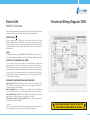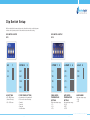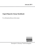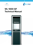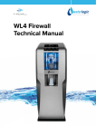
1
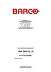
WL Cube Firewall
Technical Manual
VERSION 1
Technical Manual
Declaration
Waterlogic International Ltd
Welcome to your new Waterlogic machine.
This Technical Manual is to help you get great tasting water cup
after cup by making the most of the product’s features.
Index
Machine Overview
WL Cube Flow Diagram
Pre Delivery Inspection Procedures (PDI)
Installation Procedures
Operating Instructions
Maintenance and Servicing
Sanitizing
De-scaling
Advisory Icons
Fault Finding
Technical Specifications and Warranties
End of Life
ROHS
BioCote®
Electrical Wiring Diagram 120V
Electrical Wiring Diagram 230V
Dip Switch Setup
Wetted Parts List
Main Parts List
4
8
9
11
14
16
17
19
21
22
24
26
26
26
27
28
29
32
36
1. The installation, maintenance and sanitizing procedures must be carried out by persons trained by
Waterlogic International or their approved distributors. Do not remove any panels or covers unless
acceptable in this instruction.
2. When any abnormal case happens, firstly unplug the appliance.
3. This appliance is not intended for use by persons (including children) with reduced physical, sensory
or mental capabilities, or lack of experience and knowledge, unless they have been given supervision
or instruction concerning the use of the appliance by a person responsible for their safety.
4. Children should be supervised to ensure that they do not play with the appliance.
5. This appliance can be used by children aged from 8 years and above if they have been given
supervision or instruction concerning use of the appliance in a safe way and if they understand the
hazards involved. Cleaning and user maintenance shall not be made by children unless they are older
than 8 and supervised. Keep the appliance and its power cord out of reach of children aged less than
8 years.
6. Appliances can be used by persons with reduced physical, sensory or mental capabilities or lack of
experience and knowledge if they have been given supervision or instruction concerning use of the
appliance in a safe way and understand the hazards involved.
7. Children must not play with the appliance.
8. If the supply cord or the detachable cord sets are damaged, it must be replaced by the manufacturer,
its service agent or a similarly qualified person in order to avoid a hazard.
9. The detachable hose-sets and the connection kit used to connect the main water are supplied by
the technician. Don’t reuse the old ones.
10. The appliance is to be supplied through a residual current device (RCD) having a rated residual
operating current not exceeding 30mA.
11. This appliance is intended to be used in household and similar applications such as
- staff kitchen areas in shops, offices and other working environments;
- farm houses and by clients in hotels, motels and other residential type environments;
- bed and breakfast type environments;
- catering and similar non-retail applications.
12. This appliance contains a UV-C emitter (UV lamp)
13. Unintended use of the appliance or damage to the housing may result in the escape of dangerous
UV-C radiation. UV-C radiation may, even in little doses, cause harm to the eyes and skin.
14. Appliances that are obviously damaged must not be used.
15. The replacement of the UV lamp must be carried out by personnel trained by Waterlogic International
or their approved distributors.
16. Read the maintenance instructions before opening the appliance.
17. The appliance must be disconnected from the power supply before replacing the UV lamp.
18. The UV lamp must be replaced at 6 month intervals or when necessary. If the unit is placed
in a high use area, the UV lamp will need to be replaced more frequently.
The quartz spiral can be cleaned by using an ultrasonic bath if needed.
19. WARNING: Do not operate the UV lamp when it is removed from the appliance enclosure.
The Cube Technical Manual - Version 1, May 2014
2
3
Machine Overview
THE CUBE
HOT TANK
The hot water temperature is controlled by a Microprocessor and is set to 87°C
for standard and 95°C for extra hot. A thermal cut out is fitted to the Hot Tank to
prevent overheating. Setting the hot water temperature to 87°C also helps stop
scale forming in the hot tank, prolonging the 500 Watt element and the hot tank.
The capacity of the hot tank is 1.3 liters.
The Cube is available
in the following option:
a) Cold, Hot, Extra Hot and Ambient.
FILTERS
The filtration systems on the Cube are designed to reduce dirt and sediment
particles from the water. Furthermore, the Activated Carbon process will remove a
whole range of contaminants e.g. chlorine and pesticides. It is important for the UV
sterilization system to be supplied with clean water in order to achieve maximum
efficiency. There are many kinds of different filter combinations available from
Waterlogic to suit local water conditions.
FIREWALL CHAMBER
The Firewall chamber incorporates the in-Faucet UV and is made of aluminium and
is highly reflective. The Chamber houses the UV lamp and quartz spiral as well as
the faucet.
IN FAUCET UV
COLD TANK
The cold tank is manufactured from 304 Stainless Steel which is noncorrosive and
inert. The temperature of the Cold Tank is controlled by a microprocessor and is set
to 5°C but can be changed to 10°C or 15°C, 5°C being the ideal temperature for a
cold drink and the factory default setting. The capacity of the cold tank is 1.4 liters.
The Unique design allows the faucet area to be sterilized before, during and after
every dispense. There are two types of sensors available, the CDS Sensor and UV
monitor that detects if the UV lamp is working and the UV sensor that monitors the
UVC intensity from the UV lamp.
The Cube Technical Manual - Version 1, May 2014
4
5
UV LAMP
The UV light is a 13 Watt germicidal lamp at a wavelength of 253.7 NM, which is
very efficient at destroying bacteria in water. The UV lamp is situated in the Firewall
Chamber surrounded by a quartz spiral that attains NSF standard 55 purification
of water. The UV lamp must be replaced at 12 months intervals or when indicated
by the warning lights, and the quartz spiral cleaned by using an ultrasonic bath if
needed.
PLASTIC PANELS
The molded panels are made from recyclable ABS plastic. All the ABS plastic panels
are UV resistant and meet the standards of CE and UL. Please note that the Cube
should not be exposed to direct sunlight. Placing the Cube in direct sunlight from a
window, close to a radiator, or in a room of high ambient temperature, will affect the
efficiency of the refrigeration circuit.
PCB
The PCB (Printed Circuit Board) is the control unit for the Cube; it is responsible
for the functions of all the mechanical and electrical parts (24V DC) including the
solenoid valves, touch panel and LED’s.
COMPRESSOR
The compressor operates at 220-240V at 50Hz or 120V at 60Hz. It uses 55 grams/
1.94 Oz of R134a non-Ozone depleting refrigerant gas.
WATER PIPES AND FITTINGS
The inlet and the internal water circuit pipe size are 1/4” and 5/16”. The entire internal
water circuit and all the components which come in contact with water are food
grade NSF approved. The cold and ambient water tubing inside the machine should
not be exposed to water above 25˚C.
WATER VALVES
Dispensing of water to the customer is achieved by means of a 24V DC electrical
solenoid valve. The valves are energized every time the customer touches the
dispense button for a drink. DC voltage is used to give a positive and quieter action
of the solenoid valve.
The Cube Technical Manual - Version 1, May 2014
6
7
Pre Delivery
Inspection Procedures (PDI)
WL Cube Flow Diagram
Cold, Hot & Ambient
CAUTION:
Only competent trained technicians should work on Waterlogic products.
Waterlogic units may weigh over 25KG. We recommend caution when lifting.
Packing materials could present a trip hazard. Keep them off the floor.
Take care not to allow the power lead to get wet. If the lead gets wet it must not
be used.
IN (Water)
HOT WATER OUT
SOLENOID
VALVE
FILTER
AIR VENT
SOLENOID
VALVE
SOLENOID
VALVE
COLD WATER OUT
SOLENOID
VALVE
COLD
SENSOR
COLD
TANK
CONDENSER
SOLENOID
VALVE
HOT
TANK
FILTER
DRYER
COMPRESSOR
AMBIENT WATER OUT
The Cube Technical Manual - Version 1, May 2014
8
9
Pre Delivery
Inspection Procedures (PDI)
Installation Procedures
1. Remove packing straps and unpack unit and visually inspect for any damage.
(Report any defects to Waterlogic as soon as possible).
2. Place the unit on a suitable work bench.
3. Open the top cover by removing the two screws that fix it in place.
4. Visually inspect all electrical connections and power lead.
5. Visually inspect all water connections.
6. Remove the three screws on top of the Firewall Chamber; you may need to
remove some of the screws holding the top shelf in place to gain access to the
Chamber. Inspect the quartz spiral for damage and re-assemble.
7. Connect to a potable drinking water supply via a 1/4” John Guest tube, the supply
must be limited to 3bar.
8. Connect the power cord to an appropriate power supply and the machine.
9. Replace the top cover and re-fit the screws.
10. Note that the hot tank must be filled before any other tank.
11. Select the hot button and then the dispense button until water flows clearly, you
must dispense at least 200ml of water using the hot option for the tank to begin
heating the water.
12. Select the cold button and then the dispense button until water flows clearly.
13. After cold/hot has filled, turn on heater/compressor switch allow up to an hour
for the unit to heat and chill. Test water temperatures and ensure the water tastes
acceptable.
14. Check all of the functions of the Cube.
15. Turn off the power and water.
16. Turn unit around and drain from rear drain valves if fitted.
17. Clean and repack ready for dispatch.
18. Waterlogic recommend that all units are fully electrically (PAT) tested on site by
the commissioning engineer as damage may have occurred during transit to the
unit’s final destination.
1. Mount the Cube on a firm, level surface so the machine cannot topple or fall
over. A 50mm air gap is required the whole way around the machine to allow for
sufficient ventilation. The Cube must not be installed in direct sunlight, adjacent to a
heat source, or in an ambient room where the temperature is above 30°C or below
5°C.
2.It is advisable that the power and water supply be within a 2 metre range of
the machine, the isolation for the water and electricity should be easily accessible.
The supply of water must be from a potable source and the machine should not be
installed using an extension lead.
3. Make the water connection to the Cube via a length of ¼” flexible pipe; with
the pressure reducing valve that has been supplied installed 20cm away from the
machine before the connection into the back of the machine is made. This will
bring the pressure down to the ideal working pressure of 3bar. Minimum operating
pressure for the machine to work suitably is 2.6bar. The minimum incoming flow rate
is 1.2 litres per minute. At pressures higher than 3.2bar the machine will not function
correctly and this can lead to leaks. The water should be from a potable source and
should be allowed to run clear of any sediment before making the connection to the
Cube.
4. Check the wall socket (polarity) and then make the electrical connection to the
Cube by plugging the power lead in to the socket at the rear of the machine. Then
connect it to the electrical feed or wall power outlet. Turn on the power supply to
the Cube.
5. Turn on the red switch at the back of the Cube, the machine will now run through
a self test cycle. Once the self test cycle has completed the filter(s) will need to be
flushed.
6. Select the ambient water icon and then the central dispense button and dispense
10 liters of water. This will remove excess carbon fines and sufficiently generate the
filter.
The Cube Technical Manual - Version 1, May 2014
10
11
7. The hot water tank now needs to be filled, this is done by selecting the hot water
icon, then followed immediately by pressing and holding the main dispense button
until the tank has completely filled and water is being dispensed. Flush through 5
litres of water by continuing to select the hot option. Then repeat this process again
for the cold option.
8. After making sure the hot tank is full of water then turn on the green heater and
compressor switch at the rear of the machine.
9. Select the hot icon, then select and hold the main dispense button immediately
after selecting the hot icon.
10. Dispense at least 200ml of hot water.
11. The machine will now begin to heat / chill the water.
12. The water temperatures are pre-set at the factory to 5°c for the cold water and
87°c for the hot water.
13. The water should now be taste tested, any hint of taste in the water means
the machine needs to be flushed further with an additional 10 litres and then taste
tested again.
14. The Cube should be sanitized at installation.
INSTALLATION KIT
The Cube must be installed according to the local guidelines and it is advised that
an installation kit be used. A pressure reducing valve is supplied with the Cube and
must be installed 20cm away from the back of the machine as part of the installation;
the pressure reducing valve is set to 2.8 bar.
• The Cube should not be connected to water supplies of unknown bacterial quality
or those not already fit for human consumption. The Cube should only be connected
to a Potable drinking water supply.
• The filter on the Cube must be changed every 12 months.
• The UV lamp on the Cube must be changed every 12 months.
• The cold tank should also be flushed and sanitised every 12 months.
• Waterlogic International strongly recommends the use of an anti-flood device.
• Figure 1 is the recommended installation kit.
Fig 1. Waterlogic
Installation Kit
NOTE: Should the incoming power to the Cube become interrupted users will
need to follow points 8-12 for water to be dispensed. (This is machine dependent).
1 - 15mm Compression Inlet
2 - Double Check Valve (great for carbonated water)
3 - Adjustable Pressure Reducing Valve
4 - Integral Isolator
5 - Pressure Gauge Port
6 - Waterblock
7 - 1/4” Pushfit Outlet
The Cube Technical Manual - Version 1, May 2014
12
13
Operating Instructions
ENERGY SAVING FEATURE
The Cube has an energy saving feature that minimizes power consumption when
the machine has not been operated for 3 hours. If the sleep mode on the Cube has
been deactivated, the machine will automatically enter sleep mode after 72 hours
of no use. The Cube can be taken out of sleep mode by touching any of the buttons.
Please note the hot tank will take 10-12 minutes to reach optimum hot temperature
after the machine has been taken out of sleep mode.
DISPENSING YOUR CHOICE OF WATER IS VERY SIMPLE,
AS FOLLOWS:
1. Place your cup centrally in the dispensing area.
2.Select the type of water you wish to be dispensed and press/touch the
corresponding icon.
3.Once the icon you have selected is illuminated, select the dispense button in the
middle of the button panel.
4.Keep the dispense button depressed until your cup has reached the desired
level, and then release the button.
HOT WATER CAUTION
•Always place cup / mug in the centre of the drip tray.
•Always use a ceramic cup or a cup suitable for use with
hot water.
•Do not hold cup or place hands in dispensing area
whilst dispensing water.
•Do not dispense water in a stop start style of vending
•(Hold the button continuously until cup is full).
•Never try to fill more than one vessel at a time.
Operating Instructions
COLD WATER
Select cold water and press dispensing button.
AMBIENT WATER
Select ambient water and press dispensing button.
HOT WATER
Press and hold the hot water icon for 3 seconds until the icon has
illuminated orange, select the dispense button and hot water will
be dispensed (This safety feature prevents hot water from being
dispensed accidentally, especially by children).
EXTRA HOT WATER
Press and hold the extra hot water icon on the display panel, the icon
will flash red to indicate that the water is heating. Once the icon turns
off, the water is at the correct temperature and extra hot water can be
dispensed following the same method as Hot Water.
DISPENSING BUTTON
Press and hold this icon after selecting the type of water you wish to
be dispensed, when your cup has reached the desired level release
the button.
The Cube Technical Manual - Version 1, May 2014
14
15
Maintenance and Servicing
• The Cube must be serviced every 12 months, but we strongly recommend
the UV lamp and filters be changed every six months.
• The Cube may require any calcium build up in the hot tank to be removed,
this depends on the local water conditions.
• No paperwork or cleaning records should be stored inside the Cube.
• To reset the filter timer, hold down the hot and cold icons simultaneously
for 10 seconds.
The items required to complete this procedure are:
• Rubber Gloves
• Phillips Screwdriver
• Replacement filter cartridge(s)
• A container that can hold 5 litres
• New 13 watt UV lamp
• Non-abrasive anti-bacterial wipe or cloth
1. Put on the rubber gloves to minimise the chance of any contamination to the
machine and to protect yourself whilst the servicing procedure is being carried out.
2.You will need to stop the water supply to the machine by turning the isolation
valve to the off position and releasing the pressure by selecting the cold water
option until the water stops being dispensed.
3.Isolate the power to the Cube by turning the red and green power switches off,
these are located at the rear of the machine. Remove the power lead as a second
safety precaution.
4.Remove the top cover from the Cube by undoing the two screws located at the
back of the machine, then slide the panel backwards and lift up.
5.Take out the filter by un-clicking the loop at the top of the filter housing and
pulling it in an upward motion. If there are two filters in the machine then both of
these need to be removed.
6.Unscrew the filter housing to expose the used filter cartridge. This cartridge can
then be removed from the filter housing and replaced by a new one. Return the
filter(s) into the correct position in the machine; ensuring that it is pushed firmly into
place as the valves will be reopened by the insertion of the filter.
7.Remove the UV lamp by unplugging the UV loom, and pulling the lamp upwards.
8.Examine the UV loom for any discolouration or wear, if there is any visible remove
the loom and replace with a new one.
9.Reconnect and replace the UV lamp assembly, making sure not to touch the new
UV lamp with bare hands as this will shorten the life of the lamp.
10.Inspect all of the electrical and water connections on the machine, and take any
action necessary to prevent a fault from occurring.
11. Check the faucet nipple for any calcium build up or any visible damage and clean
or replace it if necessary.
12.Reassemble the machine and secure all panels with screws.
13.Check that the air gap around the machine is sufficient and there is nothing
blocking the ventilation.
14.Reconnect the power to the machine and turn the red switch at the rear of the
machine to the ‘on’ position. Turn on the water supply.
15.The filter(s) now need to be flushed. Do this by selecting the ambient water option
and dispensing 10 liters of water through the machine. This will sufficiently generate
the filter and remove any excess black carbon fines.
16.The green heater and compressor switch can now be turned on.
17. Select the hot icon, then select and hold the main dispense button immediately
after selecting the hot icon.
18. Dispense at least 200ml of hot water.
19. The machine will now begin to heat / chill the water.
20. Clean the outside of the machine with a non-abrasive anti-bacterial wipe or
cloth.
21. Taste the water one final time and check it is cooling and heating the water.
SANITISING
You will need the following items:
• A Phillips screwdriver
• Rubber gloves
• Aqua Dosa sanitisation fluid
• Suitable test strips to work with your sanitisation fluid
• Non-abrasive anti-bacterial wipe or cloth
• A container that can hold 5 litres
1.Put on the rubber gloves to minimise the chance of any contamination to the
machine and to protect yourself whilst the sanitisation procedure is being carried
out.
2.You will need to stop the water supply to the machine by turning the isolation
valve to the off position and releasing the pressure by selecting the cold water
option until the water stops being dispensed.
3.Isolate the power to the Cube by turning the red and green power switches off,
these are located at the rear of the machine. Remove the power lead as a second
safety precaution.
The Cube Technical Manual - Version 1, May 2014
16
17
4.Remove the top cover from the Cube by undoing the two screws located at the
back of the machine, then slide the panel backwards and lift up.
5.Take out the filter by un-clicking the loop at the top of the housing and pulling it
in an upward motion. If there are two filters in the machine then both of these need
to be removed.
6.Unscrew the filter housing(s) and remove the filter cartridge, place this to one
side as this will need to be re-fitted this once you have completed the sanitising
procedure.
7.Measure 40ml of Aqua Dosa sanitising fluid into one of the empty filter housings
and securely fasten the filter head. Re-fit the filter(s) into the machine pushing it
firmly into place.
8.Replace the top cover and re-connect the power lead, then turn on the red switch
at the rear of the machine. Turn the water supply back on.
9.Dispense cold water until the sanitisation fluid leaves the faucet, this can be
checked by dispensing cold water until the colour of the test strip has changed to
indicate the presence of the sanitisation fluid (Normally about 400-500ml of water
needs to be dispensed). Do not let any sanitisation fluid enter the hot tank.
10.Leave the sanitisation fluid inside the machine for a minimum of 10-15 minutes,
when this time has been reached, flush water through the machine until there is
no sanitisation fluid left inside. You can use your test strips to check that all of the
sanitisation fluid has been effectively flushed out.
11. Turn off the water supply to the machine and release the internal pressure by
selecting the cold option until the water stops being dispensed. Isolate the power to
the machine by switching the red switch at the rear of the machine off and removing
the power lead.
12.Remove the top cover from the machine and take out the filter(s) and unscrew
the filter housing, pour the excess water down the drain and re-fit the cartridge.
13.Re-fit the filter(s) into the machine, pushing it firmly into place. Replace the top
cover and re-connect the power lead, then turn on the red and green switches at
the rear of the machine. Turn on the water supply.
14.Select the hot icon, then select and hold the main dispense button immediately
after selecting the hot icon
15.Dispense at least 200ml of hot water
16.The machine will now begin to heat/ chill the water
17.Inspect the faucet nipple and clean or replace if it is damaged or if there any
calcium built up around it.
18.Using the antibacterial wipes, sufficiently clean the exterior panels of the
machine, including the drip tray and grill.
DE-SCALING
You will need the following items:
• A Phillips screwdriver
• A pair of rubber gloves
• De-scale solution or powder
• A funnel or large syringe
• A container that can hold 5 litres
• Non-abrasive anti-bacterial wipe or cloth
1.Put on the rubber gloves to minimise the chance of any contamination to the
machine and to protect yourself whilst the de-scaling procedure is being carried
out.
2.Allow the machine to heat the water up to normal operating temperature, as the
water inside the tank needs to be hot for the de-scaling solution to work effectively.
3.You will need to stop the water supply to the machine by turning the isolation
valve to the off position and releasing the pressure by selecting the cold water
option until the water stops being dispensed.
4.Isolate the power to the Cube by turning the red and green power switches off,
these are located at the rear of the machine. Remove the power lead as a second
safety precaution.
5.Remove the top cover from the Cube by undoing the two screws located at the
back of the machine, then slide the panel backwards and lift up.
6.Take out the filter by un-clicking the loop at the top of the housing and pulling it
in an upward motion. If there are two filters in the machine then both of these need
to be removed.
7.Unscrew the filter housing(s) and remove the filter cartridge, place this to one
side as this will need to be re-fitted this once you have completed the de-scaling
procedure.
8.Drain 50-100ml of hot water from the machine into one of the empty filter housings,
using the drainage valve at the rear of the machine. Then use this hot water from the
machine to make your de-scaling solution, following the manufacturer’s instructions
of the descaler. Re-assemble the filter housing with the de-scale solution inside.
9.Re-fit the filter(s) into the machine pushing it firmly into place. Replace the top
cover and re-connect the power lead, then turn on the red switch at the rear of the
machine. Turn the water supply back on.
10.Place your container under the dispense area and flush through 500ml of hot
water. Allow the solution to remain in the tank for 5 – 10 minutes.
11. Turn off the water supply to the machine and release the internal pressure by
The Cube Technical Manual - Version 1, May 2014
18
19
ADVISORY ICONS
selecting the cold option until the water stops being dispensed. Isolate the power to
the machine by switching the red switch at the rear of the machine off and removing
the power lead.
12.Remove the top cover from the machine. Then take out the filter(s) and unscrew
the housing, pour the excess water down the drain and re-fit the cartridge.
13.Re-fit the filter(s) into the machine pushing it firmly into place. Replace the top
cover and re-connect the power lead, then turn on the red and green switches at
the rear of the machine. Turn on the water supply.
14.Flush through the hot tank by dispensing water from the hot option. You will
need to flush approx. 4-8 litres of water.
15.Smell and then taste the water and flush more water through the tank if needed.
16.Using the antibacterial wipes, sufficiently clean the exterior panels of the
machine, including the drip tray and grill.
HOT WATER
DISPENSING
BUTTON
Press and hold the hot water icon
for 3 seconds until the icon has
illuminated orange, select the
dispense button and hot water will
be dispensed (This safety feature
prevents hot water from being
dispensed accidentally, especially
by children).
Press and hold this icon
after selecting the type
of water you wish to be
dispensed, when your
cup has reached the
desired level release the
button.
COLD
WATER
Select
cold water
and press
dispensing
button.
AMBIENT
WATER
Select
ambient
water
and press
dispensing
button.
EXTRA HOT WATER
Press and hold the extra
hot water icon on the
display panel, the icon
will flash red to indicate
that the water is heating.
Once the icon turns
off, the water is at the
correct temperature
and extra hot water can
be dispensed following
the same method
as Hot Water.
UV LAMP
HAS FAILED
Replace UV
lamp.
POWER /UV
OK
FILTER
SERVICE
DEMAND
Replace filter
cartridge.
A LEAK
HAS BEEN
DETECTED
Turn off the
water supply
and call your
authorized
service agent.
The Cube Technical Manual - Version 1, May 2014
20
21
FAULT FINDING
All fault finding procedures must be carried out by a technician trained by Waterlogic
International or their nominated distributor. Please take great care and suitable
health and safety measures when fault finding on live electrical parts.
1. No flow of water: Ensure that there is a water supply to the Cube from the
building and that the installation isolation valve is turned on. If the installation kit
has an anti-leak device included in it (as Waterlogic Installation kit) then make sure
it has not tripped.
2. No flow of water: Check that the water filters are not blocked and that they are
in date and are screwed home securely into the filter head. Waterlogic recommend
filters are changed every 6 months. Check that the internal leak detection tray has
not filled with water.
3. The hot water is not hot and cold water is not cold: Make sure the green heater
compressor switch is turned on.
4. There is hot water flow but cold water is not flowing: This may be due to the
cold water tank being frozen. If so disconnect power supply for one hour to allow
the tank to defrost, and then flush the cold water system. Check the temperature
settings are correct. If the cold tank is not frozen then check the solenoid valve is
operating correctly and being turned on and off when you select the cold option.
5. There is cold water flow but hot water is not flowing: This may be due to
calcium build up in the hot tank or the hot water outlet. De-scale the hot tank. Check
the hot water solenoid valve functions correctly and turns on and off when you
select the hot option.
6. Low flow of cold water or hot water or both: Check the building water pressure
to the Cube is 45 PSI. Check the filters are not partially blocked, that the solenoid
valves function correctly, hot tank calcium build up need to be de-scaled, cold tank
ice buildup needs to be defrosted.
7. Bad or plastic taste: If the Cube is new it may need flushing for a longer period.
8. Water leaks: Most leaks will be detected by either the internal Cube leak detection
system that will trigger an alarm, or it will trip the Waterlogic block located on the
installation kit. Should you see water leaking from the Cube, isolate the supply and
start normal fault finding procedures.
9. No power: Check the building electrical supply to the Cube is on and that the
power cord is plugged in. Ensure the red power switch at the rear of the Cube is
on. Test the Cube’s fuse. Check that the top cover isolation switch is being activated
by the top cover being locked in place correctly. If all these points are OK then start
normal fault finding procedures.
10. All Icons flashing and audible alarm: An over heat fault has been detected
please switch the Cube off immediately and start fault finding procedures.
The Cube Technical Manual - Version 1, May 2014
22
23
Technical Specifications
and Warranties
SAFETY
Subject to the standard terms and conditions of sale (a copy of which has been
provided to you), neither Waterlogic International Limited (“Waterlogic”), nor any
affiliated companies shall be liable for any damage which could affect, directly or
indirectly, any person or property.
Please be aware that any warranties accompanying the sale of our products will be
invalidated by any of the following:
• Incorrect installation
• Incorrect use of the Cube
• Unsuitable electrical and water supply
• Major short-coming of maintenance
• Technical interventions or alterations of an unauthorised nature
• Adoption and use of unapproved spare parts
• Any repair by untrained personnel
Waterlogic has a policy of constant and continual improvement and therefore
reserves the right to change specifications without prior notice, other than in the
case of significant changes.
Description
Machine Size
Machine Weight
Power Supply
Heater
Fan
Compressor
UV Lamp
Unit Total
Refrigeration Gas R134a
Cold Tank Capacity
Hot Tank Capacity
Water Connection
Minimum Water Pressure
Bar (Megapascal)
Maximum Water Pressure
Bar (Megapascal)
Recommended Water
Pressure
Bar
(Megapascal)
Minimum Incoming Flow
Rate (litres per minute)
Dispensing Flow Rate
Cold Water Temperature
Range
Hot Water Temperature
Range
Cube (120V) HCA
Cube (230V) HCA
296mm(W) x 425mm(D) x
375mm(H)
18Kg
120 Volt / 60Hz
500W / 4.2A
2W
120W / 1.7A
13W / 0.3A
635W / 6.2A
55g / 1.94OZ
1.4L
1.3L
1/4” Hose
296mm(W) x 425mm(D) x
375mm(H)
18Kg
220-240 Volt / 50Hz
500W
2W
120W
13W
635W
55g / 1.94OZ
1.4L
1.3L
1/4” Hose
3.77 (0.377)
2.6 (0.26)
6.0 (0.6)
4.14 (0.414)
4.35 (0.435)
3.0 (0.3)
1.0 lpm
1.0 lpm
1.3lpm
1.3lpm
5°C - 15°C / 41°F - 59°F
5°C - 15°C / 41°F - 59°F
80°C - 95°C / 176°F - 203°F
80°C - 95°C / 176°F - 203°F
The Cube Technical Manual - Version 1, May 2014
24
25
End of Life
Electrical Wiring Diagram 120V
Non Eu Countries
At the end of this products life, please ensure that it is disposed of in an environmentally
friendly manner which is in line with your Country requirements/guidelines.
WEEE (EU ONLY)
Please be aware that our products are covered by the Waste Electrical and
Electronic (WEEE) directive (2002/96/EC). The symbol shown above denotes
that the product should not be disposed of with general/household waste. Please
contact your supplier/service agent who will arrange for the collection and disposal
of this product.
ROHS
All Waterlogic machines comply with EC Directive (2002/95/EC) on the Restriction of
the Use of Certain Hazardous Substances in Electrical and Electrical Equipment (RoHS).
BIOCOTE® (ANTI-MICROBIAL SOLUTION)
For your added protection this product incorporates BioCote® antimicrobial
technology. Silver, in the form of silver ions, is the active ingredient utilized in
BioCote®. This silver technology is manufactured into the surface of our products,
giving them built-in sustainable antimicrobial protection. BioCote’s silver technology
has been tested by an independent laboratory to show its ability to inhibit the
growth of bacteria, mould and fungi by up to 99.9% over a 24 hour period and for
the duration of the machine life.
FREQUENTLY ASKED QUESTIONS ABOUT BIOCOTE®:
Why use BioCote®? BioCote® will help reduce the risk of cross-contamination. You
may not want to think about it, but every surface in the working environment is a
potential breeding ground for Bacteria.
How is it applied? BioCote® is applied via an additive into the manufacturing
process and will, therefore, be present throughout the molded or painted parts.
How long will BioCote® last? BioCote® will last for the usual life expectancy of your
water dispenser. It will not wear or wash out with use or cleaning.
What bacteria is BioCote® effective against? BioCote® is effective against most
common bacteria, moulds and fungi.
Please note:
BioCote® is an additional line of defence to protect between cleaning routines, it is
not a replacement for your normal cleaning and sanitisation processes.
DANGER HIGH VOLTAGES PRESENT ON THIS PCB
CARE MUST BE TAKEN WHEN LIVE TESTING
The Cube Technical Manual - Version 1, May 2014
26
27
Electrical Wiring Diagram 230V
Dip Switch Setup
THE CUBE MAIN PCB
DIP SWITCHES 1 & 2 WITH INSTRUCTIONS
DANGER HIGH VOLTAGES PRESENT ON THIS PCB
CARE MUST BE TAKEN WHEN LIVE TESTING
Dip switch 2
Dip switch 1
The Cube Technical Manual - Version 1, May 2014
28
29
Dip Switch Setup
When reading this document please note the white coloring on the diagrams
indicate the required position of the switch to determine the setting.
DIP SWITCH 1 SETUP
DP1
DIP SWITCH 2 SETUP
DP2
UV1
FILTER2 3
C-TEMP1 2
H-TEMP3 4
H-SLP5
CS
3M
5˚c
80 ˚c
ON
US
6M
10˚c
87 ˚c
OFF
12M
10˚c
87 ˚c
NO
15˚c
95 ˚c
UV SETTING
FILTER TIMER SETTING
• CS = CDS Sensor
(Used in Europe)
• US = UV Sensor
A combination of dip switches 2
& 3 is used to enter this setup.
• 3month
• 6month
• 12month
• No filter timer
COLD WATER
TEMPERATURE
SETTING
Cold water temp range:
• 5⁰c
• 10⁰c
• 15⁰c
HOT WATER
TEMPERATURE
SETTING
Hot water temp range:
• 80°C
• 87°C
• 95°C
SLEEP MODE
Hot water temp range:
• ON
• OFF
The Cube Technical Manual - Version 1, May 2014
30
31
Wetted Parts List
Hot, Cold and Ambient
48 47 46 45 44 43
41 40 39 38 37 36 35 34 33 32 31 30 29 28 27
9
1
12
2 3
4 56 7 8
42
20
10 11
26
13 14 15 16 17 18/19
21 22 23 24 25
N°
Part Description
1
2
3
4
5
6
7
8
9
10
11
12
13
14
15
16
17
18
19
20
21
22
23
24
25
26
27
28
29
JG Bulkhead Connector Union 1/4" * 1/4"
JG LLD PE Tube - Blue O.D.1/4"
JG LLD PE Tube - Blue O.D.1/4"
JG Stem Elbow Connector 1/4" * 1/4"
Solenoid Valve 24 DC (Single Spring Load)
JG Equal Tee Connector 1/4"
JG Equal Elbow Connector 1/4"
JG Stem Elbow Connector 1/4" * 1/4"
Hot & Cold Solenoid Valve 24V- 300mm CUBE
JG LLD PE Tube - Blue O.D.1/4"
JG Equal Elbow Connector 1/4"
JG LLD PE Tube - Blue O.D.1/4"
JG Equal Tee Connector 1/4"
JG Equal Elbow Connector 1/4"
JG LLD PE Tube - Blue O.D.1/4"
Solenoid Valve 24 DC (Single Spring Load)
JG Stem Elbow Connector 1/4" * 1/4"
Drain valve cap only (for 5/16" & 1/4" size)
Drain valve body only for 5/16"
JG LLDPE Tube - Blue 8mm
JG LLD PE Tube - Blue O.D.1/4"
JG Equal Elbow Connector 1/4"
1,3 litre 500W Hot Tank for Cube
Cube cold tank - 1,4 Litre
Spiral Quartz
Silicon Tube 5/16" for hot water
JG Equal Elbow Connector 1/4"
JG Stem Elbow Connector 1/4" * 1/4"
JG LLD PE Tube - Blue O.D.1/4"
The Cube Technical Manual - Version 1, May 2014
32
33
Wetted Parts List
Hot, Cold and Sparkling
N°
Part Description
30
31
32
33
34
35
36
37
38
39
40
41
42
43
44
45
46
47
48
Silicon Tube 5/16" for hot water
JG End Stop 1/4"
JG LLD PE Tube - Blue O.D.1/4"
JG Equal Tee Connector 1/4"
JG 1/4" STOPPER JG UK
JG Equal Tee Connector 1/4"
JG LLD PE Tube - Blue O.D.1/4"
JG LLD PE Tube - Blue O.D.1/4"
Solenoid Valve 24 DC (Single Spring Load)
JG Equal Tee Connector 1/4"
JG Stem Elbow Connector 1/4" * 1/4"
JG Equal Tee Connector 1/4"
JG LLD PE Tube - Blue O.D.1/4"
CBC 1 Micron 10" Filter Ass’y-PD WL Labe
Hot & Cold Solenoid Valve 24V- 300mm CUBE
5/16-1/4 Reducing Straight Connector
JG Equal Elbow Connector 1/4"
5/16-1/4 Reducing Straight Connector
JG LLD PE Tube - Blue O.D.1/4”
The Cube Technical Manual - Version 1, May 2014
34
35
Main Parts List
WL Cube Mains Parts Illustration
41
42
44
45
46
47
48
49
50
43
40
39
38
37
36
26
27
28
29
30
31 32
33
35
34
25
24
23
22
21
20
19
18
17
1
2
3
4
5
6
7
8
16
15
14
13
12
11
10
9
N°
Part Description
1
2
3
4
5
6
7
8
9
10
11
12
13
14
15
16
17
18
19
20
21
22
23
24
25
26
27
28
29
30
WL Cube Side panel left -Silver
Mark IV Al (Mirror/no gauze/Spout 18mm) for CUBE
WL Cube FW fixing bracket
WL Cube Front frame panel-Black
WL Cube Front cover -Silver
WL Cube Spout assembly bracket-Silver
WL Cube Drip tray body -Black
WL Cube Drip tray grill -Silver
Rubber feet for Cube
WL Cube Base plate-Black
1/4" Equal Elbow Connector(ST)
Leak Detection Sensor Bracket
Leak containment tray Clip (sensor 0.5mm)
1/4" stem Elbow connector
Solenoid Valve 24 DC (Single Spring Load)
Cube cold tank - 1,4 Litre
Compressor
Domestic Filter Dryer (Chinese)
WL Cube Side panel right -Silver
BulkHead Fitting 1/4"x 1/4"(ST)
Socket for Plug Connection (Domestic PST-101SL)
AC Power Fuse Holder with Fuse
Switch - Power (Red)
Switch - Heater/Compressor (Green)
Cooling Wire Condenser for Cube
Micro Door Lock S/W only
WL Cube Micro switch cover -Gray
WL Cube Back panel-Black
Fan Motor (DC 24V)
Drain valve body only for 5/16"
The Cube Technical Manual - Version 1, May 2014
36
37
N°
31
32
33
34
35
36
37
38
39
40
41
42
43
44
45
46
47
48
49
50
Part Description
Drain valve cap only (for 5/16" & 1/4" size)
Electronic fixing Bracket WL Cube
WL Cube Top Cover- Black
5/16-1/4 Reducing Straight Connector
Filter Bracket
CBC 1 Micron 10" Filter Ass’y-PD use-WL Label
Hot & Cold Solenoid Valve 24V- 300mm CUBE
1/4" Equal Tee Connector(ST)
UV 15 W Electronic Ballast (Ver. 3)
Power Transformer
WL Cube Electronics cover-Black
WL Cube UI Label-WL Logo
Cube Main PCB
WL Cube UI PCB fixing frame -Black
Cube Key and Display PCB
WL Cube Upper shelf-Black
WL Cube Silicon Tubing Guide A-White
Silicon Tube 5/16" for hot water
WL Cube Silicon Tubing Guide B-White
1,3 liter 500W Hot Tank for Cube
The Cube Technical Manual - Version 1, May 2014
38
39
USA, Canada and Mexico
Rest of the world
[email protected]
+ 1 402 884 7212
[email protected]
+ 353 1 293 1960
Waterlogic USA,
11710 Stonegate Circle,
Omaha, NE 68164
WLI Trading Ltd.
Suite 4, 2nd Floor Beacon Court,
Sandyford, Dublin 18, Ireland
www.waterlogic.com
40
ENG0266-20/05/14
Speak to a Water Expert