1
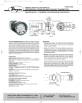
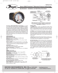
Bulletin B-34
7/21/06
10:47 AM
Page 1
Bulletin B-34
CAPSU-PHOTOHELIC® PRESSURE SWITCH/GAGE*
Specifications - Installation and Operating Instructions
Series 43000 CAPSU-Photohelic® Switch/Gage
The CAPSU-Photohelic® Switch/Gage is a most versatile, precise pressure switch combined with the CAPSUHELIC® pressure gage. Available with one or two phototransistor actuated relays. Gage reading is unaffected by
switch operation. Easy to adjust set points with knob controls. Applied pressure and switch set points are fully visible
at all times. Dead-band is one pointer width–less than 1%
of full scale. Double-pole double-throw relays can be easily
interlocked to provide variable deadband control. For positive, negative or differential pressures as low as 0 to .5˝
water column and as high as 0 to 6000 psig full scale; set
points as low as .01˝ WC on .5˝ scale unit.
PHOTOHELIC SENSING–HOW IT WORKS
In a typical control application, the CAPSU-PHOTOHELIC®
switch/gage controls between high and low pressure set
points. When pressure changes, reaching either set point
pressure, the beam from an LED to the limiting phototransistor will be cut off by the helix-driven light shield. The
resulting signal change is electronically amplified to actuate
its DPDT slave relay, and switching occurs. Dead band
between make and break 1% of full scale or less–just
enough to assure positive, chatter-free operation.
SPECIFICATIONS
1. Dimensions: 5˝ Diameter x 9 3/16˝ Length
2. Weight: 6 Lbs, 4 oz. (10 Lbs, 6 oz. Brass Case)
3. Bezel Size: 5˝ O.D. x 4˝ I.D. across gage face
4. Panel Mounting: 4 13/16˝ Dia. Hole required; Maximum
panel thickness, 5/8˝.
5. Pressure Connections: 1/4˝ NPT female, duplicate sets
on top and bottom, 436000S Models, single 1/8˝ NPT
female on top.
6. Gage Finish: Baked Gray Epoxy Hammerloid.
7. Pressure Rating: -20˝ Hg (vacuum) To 500 PSIG.
436000S models, 1.2 x full scale pressure.
8. Ambient Temperature Range: 20°F To 120°F
9. Standard Accessories: Two (2) 1/4˝ NPT pipe plugs, snap
ring, mounting ring, Four (4) #6-32 x 1 1/4˝ mounting
screws.
10. Load Relays: DPDT for each set-point. Rated for 10
Amps resistive at 117 V.A.C., 50-60 Hz.
11. Power Required: 117 V.A.C., 50-60 Hz, 5 Watts average. Optional 220 V or 240 V units available.
12. Conduit Opening: 3/4˝.
13. Accuracy: ±3% of full scale except ±2% on 43000S &
436000S Models, 4% on 43215, 43220 & 43500.
14. Service: Compatible gases or liquids. For water or water
based liquids, use only series 43000B models with brass
case. DO NOT use with hydrogen gas due to adverse reaction with rare earth magnet.
*Patent Nos. 4,011,759 4,030,365
DWYER INSTRUMENTS, INC.
P.O. Box 373 • Michigan City, IN 46361-0373, U.S.A.
Phone: 219/879-8000
Fax: 219/872-9057
www.dwyer-inst.com
e-mail: [email protected]
Bulletin B-34
7/21/06
10:47 AM
Page 2
INSTALLATION
1. Location: All parts of the Dwyer CAPSU-PHOTOHELIC®
pressure switch/gage are ruggedly constructed and will
stand a moderate amount of vibration, physical shock, and
handling. Normal care in handling and installation is all that
is required. In cases where instrument panel vibration is
severe, the panel should be spring mounted or the amplifier-relay unit mounted remotely on a more stable surface.
Select a location where the ambient temperature will not
exceed 120°F. Pneumatic pressure sensing lines may be
run any necessary distance. For example, 250 foot sensing
lines will not affect accuracy but will damp the reading
slightly. Do not restrict lines. If pulsating pressure or vibration causes excessive pointer oscillation or relay chatter,
consult factory for additional damping means. See accessory Bulletin S-101 for fittings.
2. Position: The CAPSU-PHOTOHELIC® may be mounted
as an integral package or the amplifier-load relay assembly
and housing may be mounted remotely from the indicating
gage-phototransistor unit. Extension cords with 7 pin plugs
and receptacles are available from Dwyer for interconnection of the two units.
All standard units are calibrated for use with the diaphragm
and scale in a vertical position. Special factory calibration is
available for applications requiring inclined or horizontal
positions. The exceptions are ranges under 5 inches W.C.
which are only available for vertical installation.
3. Mounting: The CAPSU-PHOTOHELIC® is normally
mounted before making electrical connections, as the electrical enclosure is independent of the mounting means and
may be removed at any time.
A. Panel Mounting: Normal mounting is flush or through
panel as shown in Fig. 2. Be sure to allow 4 3/8˝ extra space
behind the unit for electrical enclosure removal. Make a single 4 13/16˝* diameter hole in the panel. Insert the entire
CAPSU-PHOTOHELIC® unit from the front, then slip on the
mounting ring and snap ring from the rear. Seat the snap
ring in its groove, back up the mounting ring against snap
ring and tighten the four (4) 1 1/4˝ No. 6-32 clamp screws
provided. If behind panel space is critical, the amplifier-relay
unit can be mounted remotely. See the Remote-Relay
Mounting Instructions for details.
* For convenience, this hole can be made with Model 730E, 120
MM chassis punch manufactured by Greenlee Tool Co. Contact
your machine tool distributer. Not available from Dwyer
Instruments.
Bulletin B-34
7/21/06
10:47 AM
Page 3
B. Gage Mounting with Relay Package Remote: Where
it is preferred to install the amplifier-relay unit separate from
the gage, (usually due to space limitations) the gage may
either be panel mounted as in figure 3A. For surface mounting, use the hole layout in figure 3B. CAUTION: When the
gage is surface mounted, two 1/4˝ dia. holes must be located as shown for blow-out protection. This assures that if the
gage is overpressured, thus causing a failure, pressure will
be safely vented out the back. Failure to keep these holes
clear could result in personal injury and/or property damage
since the excessive pressure could be forced into the front
cover which would then blow off.
C. Remote Relays Mounting: The amplifier – relay unit
may be mounted remotely as shown in Fig. 4A. Use the hole
layout as shown in Fig. 4B for this option. Additional mounting information for special requirements is available from the
factory.
4. Pressure Connections & Zeroing: After installation,
but before making pressure connections, set the indicating
pointer exactly on the zero mark by using the zero adjust
screw located near the bottom of the front cover. This
adjustment must be made with both high and low taps
vented to atmosphere.
Make pressure connections to the 1/4˝ NPT female taps
using adapters appropriate for the type of tubing being
used. 1/4˝ O.D. or larger copper or stainless steel is recommended. Either of the duplicate sets may be used, but normally the upper set is preferred for air or gases and the
lower for liquids. This allows condensate to be periodically
drained out the bottom on gas service and trapped air to be
purged out the top on liquid service. Optional A-314 Bleed
Fittings simplify either operation. It is especially important
that all air be bled from the gage on liquid service to assure
accurate readings.
For differential pressures, use both high and low taps and
plug the unused pair. For positive pressure, use either high
tap, plug the other, and leave the high side vented to atmosphere. Two 1/4˝ NPT pipe plugs are furnished with each
statement.
NOTE: If the Photohelic switch/gage is over pressured,
pointer may “jump” from full scale back to zero and remain
there until the excess pressure condition is relieved. Users
should be aware of possible false zero pressure indications
under this conditions.
Bulletin B-34
7/21/06
10:47 AM
Page 4
ELECTRICAL CONNECTIONS
1. Cover: The amplifier-relay unit has an easy to remove
housing. Remove the three (3) screws as shown in Fig. 5
and slide the housing off. Make all the electrical connections
before reinstalling and refastening the housing.
2. Conduit: Electrical access to the connection box portion
of the relay housing is by bottom opening for 3/4˝ conduit.
Use of flexible conduit is recommended. It should be supported from the panel or other suitable surface to prevent
the wiring system from exerting undue strain on the instrument. See Fig. 5.
3. Terminal or Connection Board Layout: In Fig. 6,
“Terminal Board,” Section A contains the connections for
th load or slave relay acutated by the high or right set-point
phototransistor. This relay is a double pole, double throw
type. The two top connections are normally closed, the two
middle connections are normally open, and the bottom
connections are the common pair. The relay is in its normal
or De-Energized position when pressure is below the right
hand set-point.
Section D is exactly the same as Section A except that its
load or slave relay is controlled by the low or left set-point.
The De-Energized position is below the left hand pointer
set-point.
Section B contains the external connections to the holding
coil circuit for the high or right set-point relay and Section
C contains similar connections for the low or left set-point
relay. The function and use of these connections varies
somewhat depending on the circuit style of the instrument.
See paragraphs 5 and 6 for details.
Bulletin B-34
7/21/06
10:47 AM
Page 5
Section E contains the power connections for the control
unit transformer primary. The transformer in turn supplies
reduced voltage power for the LED, phototransistor, amplifier unit, and load relay pull in and holding coils.
Connections must always be made to this section in order
to put the unit in operation. Standard units are designed to
117 V.A.C. input to the transformer. Special units are also
available for other voltages.
Separate Ground Wire attachment is provided for by a
No. 6-32 screw on the mounting bracket near the conduit
opening. An additional ground wire connection is located on
the side of the gage body for use when the amplifier-relay
unit is mounted remotely.
Single Set-Point instruments are furnished with the right
or high set-point components and circuitry in place. These
are connected to Sections A and B of the terminal board.
The left or low set-point components are omitted.
4. Circuit Style: The CAPSU-PHOTOHELIC® is available
with several factory installed optional internal circuits. They
are identified as to style by a label shown in Fig. 7. This label
is mounted prominently on the terminal board of each
instrument. The letter H denotes a circuit in which the relay
can be made to latch or remain energized after pressure
increase to its set-point.
The letter L denotes a circuit in which the relay can be made
to latch or remain de-energized after pressure decrease to
its set-point. Two letters are required to fully identify a dual
set-point unit. Thus, circuit style HH, which is standard, is a
dual set-point circuit which has provisions for latching on
pressure increase to either set-point. Single relay units are
identified by the letters SR followed by H for the standard
unit or L for the special low latch unit. Units for use with
other than standard 117 VAC will be so indicated on the
label.
5. Dual Set Point Automatic Reset: Circuit Style HH is
used for simple on-off switching applications. To place in
service, connect load circuits to the appropriate terminals in
Section A (Fig. 6) for the right set-point and Section D for
the left set-point. Note that the N.O. contacts are open
when the gage pressure pointer is to the left of the set-point
pointers. No connections are necessary in Sections B and
C. Make external ground connections as required and connect power to Section E for the control unit. To use circuit
style LL for automatic reset, a jumper wire must be installed
between the upper and lower terminals in sections B and/or
C.
6. Dual Set Point Manual Reset: Circuit Style HH may
also be used for manual reset applications where it is
desired to have maintained contact on either relay following
pressure increase above its set-point. Load or signal connections are made to the appropriate terminals in Sections
A and D (as in paragraph 5 above). Connect terminals in
Sections B and C through normally closed switches or push
buttons as shown in Fig. 8. Use of “dry-circuit” type switches such as Dwyer Part No. A-601 with palladium, gold, etc.
or rotary wiping action type contacts it recommended.
Make external ground connections as required and connect
power to Section E for the control unit.
Circuit style LL is used for manual reset applications which
require that contact be maintained following pressure
decrease below the set-point. Load connections are made
to the appropriate terminals in Sections A and D. A normally open type manual reset switch such as Dwyer Part No.
A-601 is connected to the terminals in sections B and C.
The circuit must be “armed” by momentarily closing the
switch while the black pointer is to the right of the set-point.
From that point on, the circuit will latch on pressure
decrease below the set-point and remain latched on pressure increase until manually reset with the optional switch.
Bulletin B-34
7/21/06
10:47 AM
Page 6
7. Dual Set Point Automatic and Manual Reset
Combinations: Circuit style HH may be used with either
set-point wired and operating as in paragraph 5 above and
other set-point wired and operating as in paragraph 6.
8. High Low Limit Control–Dual Set-Point: Circuit Style
HH may be used to control fans, dampers, pumps, etc.,
between the set-points of a CAPSU-PHOTOHELIC®. To
accomplish this, use one set-point relay to reset the other
as shown in the wiring diagram Fig. 9. In this typical application, the load (for instance a fan) would be connected to
the N.C. contacts of the right set-point relay. Section A (Fig.
6). On pressure rise to the right set-point, its relay would pull
in and hold even though pressure might then fall below that
set-point. If the pressure continued to fall to the left setpoint, its relay would automatically be DE-ENERGIZED,
return to its normal position and in so doing, open the holding coil circuit from Section B (Fig. 6). The right set-point
relay would thus be reset and the cycle could repeat.
9. Dual Set-Point Special Purpose Circuits: Circuit Style
LL may be used where manual reset following maintained
contact on pressure decrease to either set-point is desired.
Circuit Styles HL and LH are combination units. For special
combinations of features, special units, and detailed
instructions regarding their use, consult the factory.
10. Single Set-Point PHOTOHELIC®: The single set-point
CAPSU-PHOTOHELIC® is furnished with the right set-point
only. Terminals in Section A and B (Fig. 6) are connected to
this relay. Circuit Style SRH is wired for automatic reset as
in paragraph 5 above. Manual reset is accomplished by
adding a normally closed reset switch or push button to the
circuit as described in paragraph 6 above.
11. Single Set-Point Special: Manual reset after actuation
on falling pressure can be obtained by using Circuit Style
SRL. Consult the factory for special units and detailed
instructions regarding their use.
12. Placing in Service: In normal operation each relay is
de-energized when the pressure applied to the instrument
is below its set-point. Special low-latching units will ordinarily have to be reset before placing on the line in normal operation.
13. Failure Mode: The CAPSU-PHOTOHELIC® circuit
design provides certain protection in the event of a loss of
pressure or electrical power. In either case, both relays will
de-energize, returning to their normal “zero pressure” state.
The exceptions to this are models with center zero ranges.
Because the relays on all standard models are always energized when the indicating (black) pointer is to the right of
their respective set points, the relay action on loss of pressure will depend on set-point position, since either of them
could be located to the left of zero. As an example; if the left
pointer were set at -2 in. w.c. and negative pressure was 3 in. w.c., a loss of that pressure would allow the black
pointer to return to the center and thus cause the low setpoint relay to energize.
If the LED should fail, only the left-low relay will deenergize. The right-high relay will react as if pressure were
above its set-point and will remain energized even though
pressure might be below that setting. In this situation, only
termination, only termination of electrical power will allow
the right-high relay to de-energize.
MAINTENANCE AND SERVICE
Dwyer CAPSU-PHOTOHELIC® Switch/Gages are precision
instruments, expertly assembled and calibrated at the factory. They require no lubrication or periodic servicing. If the
interior is protected from dust, dirt, corrosive gases and fluids, years of trouble-free service may be expected. Zero
adjustment should be checked and reset occasionally to
maintain accuracy. Any repairs necessary to either the
Dwyer Capsuhelic® pressure gage or the electronic components should be performed by a trained instrument
mechanic. In most cases, this is best accomplished by
returning
the
complete
CAPSU-PHOTOHELIC®
Switch/Gage to the Dwyer factory.
Bulletin B-34
7/21/06
10:47 AM
Page 7
SERIES 43000
CAPSU-PHOTOHELIC®
PRESSURE SWITCH/GAGE
MODELS AND RANGES
Minor
Div.
Model
Number
Range,
MM of
water
43302
Range,
Zero
Center
Inches of
Water
1-0-1
.05
43000-20 MM
0-20
.50
43304
2-0-2
.10
43000-25 MM
0-25
.50
43000-50 MM
0-50
1.0
43000-80 MM
0-80
2.0
43000-100 MM
0-100
2.0
Model
Number
Range,
Inches of
Water
Minor
Div.
Model
Number
43000-0
0-0.5
.01
43001
0-1.0
.02
43002
0-2.0
.05
43310
5-0-5
.20
43003
0-3.0
.10
43320
10-0-10
.50
43004
0-4.0
.10
43330
15-0-15
1.0
43005
0-5.0
.10
43006
0-6.0
.20
Range,
PSIG
Minor
Div.
PSIG
43008
0-8.0
.20
43010
0-10
.20
43015
0-15
.50
43020
0-20
.50
43025
0-25
.50
43030
0-30
1.0
43040
0-40
1.0
43050
0-50
1.0
43060
0-60
2.0
43080
0-80
2.0
43100
0-100
2.0
43150
0-150
5.0
43200
0-200
5.0
43300
0-300
10.0
Minor
Div.
MM
Model
Number
43000-125
43000-250
43000-500
43000-750
Pa
Pa
Pa
Pa
Model
Number
Range,
Pascals
Minor
Div.
Pascals
0-125
0-250
0-500
0-750
5.0
5.0
10.0
25.0
Range,
Zero
Center
Pascals
43300-500 Pa 250-0-250
Model
Number
Range,
CM of
water
Minor
Div.
CM
43201
0-1
.02
43202
0-2
.05
43203
0-3
.10
43204
0-4
.10 43000-15 CM
0-15
.50
43205
0-5
.10 43000-20 CM
0-20
.50
43210
0-10
.20 43000-25 CM
0-25
.50
43215
0-15
.50 43000-40 CM
0-40
1.0
43220
0-20
.50 43000-50 CM
0-50
1.0
43230S
0-30
1.0
43000-80 CM
0-80
2.0
43240S
0-40
1.0
43000-100 CM
0-100
2.0
43260S
0-60
2.0
43000-150 CM
0-150
5.0
43280S
0-80
2.0
43000-200 CM
0-200
5.0
43210S
0-100
2.0
43000-250 CM
0-250
5.0
43220S
0-200
5.0
43000-300 CM
0-300
10.0
43230S
0-300
10
43600S
0-400
10
43600S
0-600
20
43601S
0-1000
20
43602S
0-2000
50
43400
0-400
10.0
43604S
0-4000
100
43500
0-500
10.0
43606S
0-6000
200
Model
Number
Model
Number
43300-4 CM
43300-10 CM
43300-30 CM
Range,
Zero
Center
CM of
Water
Minor
Div.
CM
2-0-2
5-0-5
15-0-15
.10
.20
1.0
Note: The CAPSU-Photohelic® pressure switch/gage may
be used in an Underwriters Laboratories approved industrial control panel if the usage conforms to U/L specifications for the acceptance of unlisted components.
Model
Number
Minor
Div.
Pascals
10.0
Minor
Range,
Div.
Kilopascals Kilopascals
43000-1 kPa
0-1
.02
43000-1.5 kPa
0-1.5
.05
43000-2 kPa
0-2
.05
43000-3 kPa
0-3
.10
43000-4 kPa
0-4
.10
43000-5 kPa
0-5
.10
43000-8 kPa
0-8
.20
43000-10 kPa
0-10
.20
43000-15 kPa
0-15
.50
43000-20 kPa
0-20
.50
43000-25 kPa
0-25
.50
43000-30 kPa
0-30
1.0
Model
Number
43300-1 kPa
43300-3 kPa
Range,
Minor
Zero
Div.
Center
Kilopascals Kilopascals
.5-0-.5
1.5-0-1.5
.02
.10
Bulletin B-34
7/21/06
10:47 AM
Page 8
CAPSU-Photohelic® Switch/Gage
1.
2.
3.
4.
5.
6.
7.
Capsu-Photohelic® Gage Body & Sensor Assembly.
Cover, Knob and Zero Adjust Assembly.
“O” Ring Seal for Cover.
Bezel with Groove for Snap Ring.
Mounting Ring.
Snap Ring (Mounting).
Screws for Mounting Ring, #6-32 x 1 1/4˝ RHMS, (4)
Required.
8. Optional A-314 Bleed Fitting, 1/4˝ NPT.
9. 1/8˝ NPT Mounting Stud.
10. Flange Plate and Bracket Assembly for Circuit Board
with Mounting Screws.
11. Lock Washer.
12. 1/8˝ NPT Mounting Nut.
13. Amplifier-Relay Circuit Assembly.
14. Gasket for Housing.
15. Housing for Amplifier-Relay Unit with (3) #6-32 x 5/16˝
RH Machine Screws.
16. 1/4˝ NPT Pipe Plugs (Not Shown).
When corresponding with the factory regarding
CAPSU-Photohelic® switch/gage problems, refer
to the call-out numbers in this view. Be sure to
include range, single or double circuit style letters
where required. Field repair is not recommended;
contact the factory for service information.
Printed in U.S.A. 6/93
DWYER INSTRUMENTS, INC.
P.O. Box 373 • Michigan City, IN 46361-0373, U.S.A.
FR 16-440405-00
Phone: 219/879-8000
Fax: 219/872-9057
www.dwyer-inst.com
e-mail: [email protected]