1
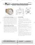
B-36A:bulletin B-36A
12/13/10
10:18 AM
Page 1
Bulletin B-36A
SERIES 3000 SGT PHOTOHELIC®
DIFFERENTIAL PRESSURE SWITCH/GAGE TRANSMITTER
Specifications – Installation and Operating Instructions
2-1/16
[52.39]
2
[50.80]
1/8 NPT FEMALE PNEUMATIC TAPS
PANEL 5/8 [15.88] MAX
3/4 [19.05]
CONDUIT OPENING
4-3/8
[111.13]
HOUSING REMOVAL
5-1/2
5
Ø4 [127.00] [139.70]
[101.60] 0.D.
O.D.
FACE BEZEL MOUNTING
RING
1-1/4
[31.75]
Ø4-3/4 3-7/8
[120.65] [98.43] SQ
FLANGE HOUSING
3-7/8
[98.43]
5-1/8
[130.18]
3/16
[4.76]
2-1/2
[63.50]
5/8
[15.88]
Figure A
The Series 3000 PHOTOHELIC® SGT is a versatile 3-in-1 instrument combining a
time-proven Magnehelic® differential pressure gage, low/high limit pressure
switches and a 4-20 mA pressure transmitter. It is designed to measure and control
positive, negative or differential pressure of air or other non-combustible, noncorrosive gases. Gage reading is unaffected by switch or transmitter operation.
Switch set points are easily adjusted with knobs located on gage face. Applied
pressure and switch set points are fully visible at all times. Deadband is one pointer
width, less than 1% of full scale. Each set point controls a DPDT relay and both can
be interlocked to provide variable deadband control. The 2-wire transmitter
operates independently, driven by a separate external 10-35 VDC power supply.
Separate zero and span potentiometers are provided inside the rear electronics
package for easy field adjustment.
PHYSICAL DATA
Ambient Temperature Range: 20 to 120˚F (-6.7to 49˚C).
Maximum Pressure: 2 psi (13.8 kPa) for ranges up to 5˝ w.c.; 5 psi (35 kPa) for
ranges 6, 10˝ w.c.; 10 psi (69 kPa) for ranges 20, 30˝ w.c.; 25 psi (170 kPa) for
above ranges.
Accuracy: ±2% of full scale at 70˚F (21.1˚C) (3% on -0).
Pressure Connections: 1/8˝ NPT(F).
Case Finish: Baked dark gray epoxy enamel.
Conduit Opening: 3/4˝.
Standard Accessories: (2) 3/16˝ tubing to 1/8˝ NPT brass adapters for rubber or
vinyl tubing, (1) mounting ring. (1) snap ring, (4) 6-32 x 2˝ mounting screws,
instructions.
Compatibility: Use only with air or other non-combustible, non-corrosive gases.
Weight: 4 lb, 12oz (2.15 kg).
INSTALLATION
1. Location: Select a clean, dry, vibration-free location where ambient
temperatures will be between 20 and 120˚F (-6.7 and 49˚C). Tubing supplying
pressure to the instrument can be practically any length but long runs will
increase response time slightly.
2. Position: The PHOTOHELIC® SGT is factory calibrated for use with scale in a
vertical plane. Operation at other angles may affect accuracy and/or require
zero adjustment. Most models can be specially calibrated at the factory for
other positions if specified at time of ordering. Ranges below 1˝ w.c. must be
used only with scale vertical.
3. Mounting: Normal mounting is flush or through panel as shown in Figure B.
Allow 4-3/8˝ space behind the unit for electrical enclosure removal. Make 4-3/4˝
diameter hole in panel. When installing multiple units, it may be preferred to
obtain a Model 730E, 120 mm chassis punch as manufactured by Greenlee
Tool Co. and available from your machine tool distributor.
Insert PHOTOHELIC® SGT from front of panel, slip the mounting ring over the
case from rear and seat the snap ring in its groove. Thread the (4) 6-32x2˝
machine screws into mounting ring, back it against snap ring and tighten
screws to back of panel. An alternative to flush mounting is the optional A-371
Surface Mounting Bracket. Unit is mounted in this bracket as described above
and bracket is then surface mounted. Contact factory for details.
SNAP RING GROOVE
ELECTRICAL SPECIFICATIONS (Switches)
Power Supply: 117 VAC.
Current Consumption: 5 watts average.
Contact Rating: 10A @ 24 VDC or 120 VAC, 6A @ 240 VAC.
ELECTRICAL SPECIFICATIONS (Transmitter)
Power Supply: 10.0 to 35 VDC.
Output Signal: 4-20 mA DC, 2-wire (limited at 38 mA).
Loop Resistance: 0-1250 ohms.
Current Consumption: 38 mA DC, maximum.
Span and Zero Adjustment: Multi-turn potentiometers, internally accessible
Thermal Errors: ±1% per 50˚F typical
Warm-Up Time: 10 minutes.
DWYER INSTRUMENTS, INC.
P.O. BOX 373 • MICHIGAN CITY, INDIANA 46361 U.S.A.
Ø4-3/4 [120.65]
MOUNTING HOLE
Figure B
Phone: 219/879-8000
Fax: 219/872-9057
www.dwyer-inst.com
e-mail: [email protected]
B-36A:bulletin B-36A
12/13/10
10:18 AM
Page 2
4. Zeroing & Pneumatic Connections: After unit is installed in its final mounting
position, use the screw at bottom of front cover to adjust pointer for exact zero
reading. This must be done with both pressure ports open and vented to
atmosphere.
SECTION C
SECTION B
SECTION D
SECTION A
(A) For positive pressure, connect tubing to HIGH PRESSURE port and vent LOW
PRESSURE port to atmosphere.
SECTION E
(B) For negative pressure (vacuum), connect tubing to LOW PRESSURE port and
vent HIGH PRESSURE port to atmosphere.
When either port will be left open to atmosphere, we suggest installation of
optional A-331 Filter Vent Plug to keep gage interior clean.
Figure D
(C) For differential pressure, connect higher pressure to HIGH PRESSURE port
and lower pressure to LOW PRESSURE PORT.
NOTE: If the PHOTOHELIC® SGT is on over-pressured beyond its full scale
range, pointer could jump from full scale back to zero and remain there until the
excess pressure condition is relieved. Users should be aware that this condition
would cause a false indication of zero pressure and subsequently affect setpoints and transmitter output signal.
SWITCH/GAGE WIRING CONNECTIONS
To make electrical connections, remove the (3) cover screws and slide cover off. All
wiring should be fed through flexible conduit attached to conduit opening at bottom
of electrical package. Conduit should be attached to the panel of other suitable
support to avoid excess strain on the instrument. See Figure C.
COVER MOUNTING
SCREWS
CAUTION: Do not apply electrical current to terminals in Sections B and C.
Separate Ground Wire attachment is provided for by a No. 6-32 screw on the
mounting bracket near the conduit opening.
Single Set-Point instruments are furnished with the right or high set-point
components and circuitry in place. These are connected to Sections A and B of
the terminal board. The left or low set-point components are omitted.
2. Circuit Style: The PHOTOHELIC® is available with several factory installed
optional internal circuits. They are identified as to style by a label shown in
Figure E. This label is mounted prominently on the terminal board of each
instrument. The letter H denotes a circuit in which the relay can be made to
latch or remain energized after pressure increase to its set-point.
The letter L denotes a circuit in which the relay can be made to latch or remain
de-energized after pressure decreases to its set-point. Two letters are required
to fully identify a dual set-point. Two letters are required to fully identify a dual
set-point unit. Thus, circuit style HH, which is standard, is a dual set-point circuit
which has provisions for latching on pressure increase to either set-point.
Single relay units are identified by the letters SR followed by H for the standard
unit or L for the special low latch unit. Units for use with other than standard 117
VAC will be so indicated on the label.
FLEXIBLE CONDUIT
SUPPORT CONDUIT
FROM PANEL
Figure C
1. Low/High Set-Point Wiring Connections
The rear terminal board contains connections for low and high set-points,
holding coil circuits and line power supply. Transmitter connections are located
behind this terminal board. See TRANSMITTER WIRING CONNECTIONS for
complete information.
Section A contains DPDT connections for the right or high set-point and Section
D contains identical connections for the left or low set-point.
Terminals in Section B are for control of the holding coil circuit for the right, high
set-point and Section C contains identical connections for the left, low set-point.
These holding coil circuits are typically used to allow latching set-points with
manual reset or for adjustable deadband operation with one set-point wired to
reset the other. See paragraphs 3 and 4 for details. Do Not Connect Line
Current to Sections B or C. Section E (L1 and L2) contains power supply
connections for the control unit transformer primary. The transformer in turn
supplies reduced voltage power for the LED, phototransistor, amplifier unit,
load relay pull-in and holding coils. Connections must always be made to this
section for the unit to operate. Standard units require 117 VAC but options are
available for other power sources. See label on terminal board for correct
voltage and circuit style.
2
Figure E
3. Dual Set Point Automatic Reset: Circuit Style HH is used for simple on-off
switching applications. To place in service, connect load circuits to the
appropriate terminals in Section A (Figure D) for the right set-point and Section
D for the left set-point. Note that the N.O. contacts are open when the gage
pressure pointer is to the left of the set-pointers. No connections are necessary
in Sections B and C. Make external ground connections as required and
connect power to Section E for the control unit. To use circuit style LL for
automatic reset, a jumper wire must be installed between the upper and lower
terminals in Sections B and/or C.
4. Dual Set Point Manual Reset: Circuit Style HH may also be
used for manual reset applications where it is desired to have maintained
contact on either relay following pressure increase above its set-point. Load or
signal connections are made to the appropriate terminals in Sections A and D
(as in paragraph 3 above). Connect terminals in Sections B and C through
normally closed switches or push buttons as shown in Figure F. Use of “drycircuit” type switches such as Dwyer Instruments, Inc. Part No. A-601 with
palladium, gold, etc. or rotary wiping action type contacts is recommended.
Make external ground connections as required and connect power to Section
E for the control unit.
Circuit style LL is used for manual reset applications which require that contact
be maintained following pressure decrease below the set-point. Load
connections are made to the appropriate terminals in Sections A and D. A
normally open type manual reset switch such as Dwyer Instruments, Inc. Part
No. A-601 is connected to the terminals in Sections B and C. The circuit must
be reset or “armed” by momentarily closing the switch while the black pointer is
to the right of the set-point. From that point on, the circuit will latch on pressure
decrease below the set-point and remain latched on pressure increase until
manually reset with the optional switch.
B-36A:bulletin B-36A
12/13/10
10:18 AM
Page 3
RESET
NC
RESET
NC
NO
8.
Single Set-Point PHOTOHELIC® SGT: The single set-point PHOTOHELIC®
SGT is furnished with the right set-point only. Terminals in Sections A and B
(Figure D) are connected to this relay. Circuit Style SRH is wired for automatic
reset as in paragraph 3 above. Manual reset is accomplished by adding a
normally closed reset switch or push button to the circuit as described in
paragraph 4 above.
9.
Single Set-Point Special: Manual reset after actuation on falling pressure
can be obtained by using Circuit Style SRL. Consult the factory for special
units and detailed instructions regarding their use.
NO
HI
LO
C
NO
NC
NC
NO
C
C
NO
NC
NC
NO
C
L2
L1
Figure F
CAUTION: Do not apply electrical current to terminals in Sections B and C.
Manual Reset with Circuit HH
5. Dual Set Point Automatic and Manual Reset Combinations: Circuit style HH
may be used with either set-point wired and operating with automatic reset as
described in paragraph 3 above and other set-point wired and operating with
manual reset as described in paragraph 4.
6. High Low Limit Control – Dual Set-Point: Circuit Style HH may be used to
control fans, dampers, pumps, etc., between the set-points of a PHOTOHELIC®
SGT. To accomplish this, use one set-point relay to reset the other as shown in
the wiring diagram Figure G. In this typical application, the load (for instance a
fan) would be connected to the N.C. contacts of the right set-point relay,
Section A (Figure D). On pressure rise to the right set-point, its relay would pull
in and hold even though pressure might then fall below that set-point. If the
pressure continued to fall to the left set-point, its relay would automatically be
DE-ENERGIZED, returned to its normal position and in so doing, open the
holding coil circuit from Section B (Figure D). The right set-point relay would
thus be reset and the cycle could repeat.
10. Placing in Service: In normal operation each relay is de-energized when the
pressure applied to the instrument is below its set-point. Special low-latching
units will ordinarily have to be reset before placing on the line in normal
operation.
11. Failure Mode: The PHOTOHELIC® SGT circuit design provides certain
protection in the event of a loss of pressure or electrical power. In either case,
both relays will de-energize, returning to their normal “zero pressure” state.
The exceptions to this are models with center zero ranges. Because the relays
on all standard models are always energized when the indicating (black)
pointer is to the right of their respective set points, the relay action on loss of
pressure will depend on set-point position, since either of them could be
located to the left of zero. As an example; if the left pointer were set at -2 in.
w.c. and negative pressure was -3 in w.c., a loss of that pressure would allow
the black pointer to return to the center and thus cause the low set-point relay
to energize.
If the LED should burn out, only the left-low relay will de-energize. The righthigh relay will react as if pressure were above its set-point and will remain
energized even though pressure might be below that setting. In this situation,
only termination of electrical power will allow the right-high relay to deenergize.
TRANSMITTER WIRING CONNECTIONS
Electrical connections for the two-wire, 4-20 mA transmitter circuit are made to the
small terminal block mounted behind the larger switch/gage terminal board. Wiring
should enter this area through the 5/8˝ dia. hole at bottom of electronics chassis.
See Figure H.
RESET JUMPERS
POSITIVE
NEGATIVE
Figure H
1/3 HP*
120 V
LOAD
Figure G
*Note: For larger motors, use the Photohelic® in a maintained contact, 120 Volt
Control or Push Button Circuit of the motor starter.
7.
Dual Set-Point Special Purpose Circuits: Circuit Style LL may be used
where manual reset following maintained contact on pressure decrease to
either set-point is desired. Circuit Styles HL and LH are combination units. For
special combinations of features, special units, and detailed instructions
regarding their use, consult the factory.
The transmitter function of the PHOTOHELIC® SGT operates independent of the
low/high switch set-points and requires a separate external power supply delivering
10.0 to 35 VDC with minimum current capability of 40mA to power its control loop.
Refer to Figure J for connection of the power supply, transmitter and receiver. The
range of appropriate receiver load resistance (RL) values for various power supply
voltages is defined by the formula and graph in Figure K. Shielded two wire cable
is recommended for control loop wiring and the negative side of the loop can be
grounded if proffered. The receiver can be connected in either the positive or
negative side of the loop. If the polarity of the transmitter or receiver is inadvertently
reversed, the loop will not function properly but no damage will be done to the
transmitter.
The maximum wire length between the transmitter and receiver is a function of wire
size and receiver resistance. Connecting wires should not contribute more than
10% of the receiver resistance to total current loop resistance. Where long runs
(over 1,000 feet) are required, select receivers with higher resistances to minimize
size and thus cost of wiring. For runs up to 100 feet, wire as small as 24 AWG can
be used.
3
B-36A:bulletin B-36A
12/13/10
10:18 AM
Page 4
NOTE: RECEIVER MAY BE IN SERIES WITH
+ OR - LEG OF CONTROL LOOP
SERIES
3000 SGT
PRESSURE
TRANSMITTER
POWER
SUPPLY
10-35 VDC
RECEIVER
Maintenance
After final installation of the PHOTOHELIC® SGT no routine maintenance is
necessary. A periodic check of calibration is recommended following the procedure
under TRANSMITTER OUTPUT CALIBRATION. Otherwise, these units are not
field repairable and should be returned, freight prepaid, to the following address if
service is necessary. Be sure to include a brief description of the problem plus any
relative application information available.
TOTAL RECEIVER RESISTANCE (Ω)
Figure J
1500
1400
1300
1200
1100
1000
900
800
700
600
500
400
300
200
100
50
Multiple Receiver Installation
An advantage of the standard 4-20 mA DC output signal used in Series 3000 SGT
switch/gage/transmitters is the compatibility with a wide range of receivers. Devices
such as the A-701 Digital Readout, a chart recorder and other process control
equipment can all be operated simultaneously. It is only necessary that all devices
be designed for a standard 4-20 mA DC input, the proper polarity of input
connections be observed and the combined receiver resistances not exceed the
maximum for the current loop. If any receiver indicates a negative or downscale
reading, the signal input leads are reversed.
MAXIMUM VALUE (1250Ω)
Dwyer Instruments, Inc.
Attn: Repair Department
102 Highway 212
Michigan City, IN 46360
RL MAX. = Vps-10.0
20 mA DC
OPERATING
REGION
0
5
10 13 15
20
VDC
25
30
35
40
Figure K
Voltage Input
The PHOTOHELIC® SGT can easily be adapted for receivers requiring 1-5 VDC
input. Insert a 250 ohm, 1/2 watt resistor in series with the current loop but parallel
to the receiver input. Locate this resistor as close as possible to the receiver input.
Because resistor accuracy directly influences output signal accuracy, we
recommend use of a precision ±0.1% tolerance resistor to minimize this effect.
Transmitter Output Calibration
Each unit is factory calibrated to produce 4mA DC of loop current at zero pressure
and 20mA DC at full scale. To check calibration use the following procedure.
1. Connect a controllable source of pressure to the high pressure port and leave
the low pressure port vented to atmosphere.
2. With transmitter connected to its companion receiver and power supply, insert
an accurate milliammeter ranged to approximately 30 mA in series with the
current loop.
3. Apply electrical power to the system and check for proper operation. Slowly
apply pressure and confirm that loop current increases above the 4 mA zero
pressure value.
4. Span and zero controls are located behind the terminal board as shown in
Figure L. Apply pressure until gage reads full scale and adjust span control for
20 mA loop current.
SPAN
ZERO
Figure L
5. Relieve pressure and adjust the zero control for a reading of 4 mA loop current.
6. Zero and span controls are slightly interactive so steps 4 and 5 should be
repeated until outputs are consistently 4 and 20mA, respectively.
7. Remove the milliammeter from the current loop, make connections to system
pressure sources and place unit in service.
©Copyright 2010 Dwyer Instruments, Inc.
DWYER INSTRUMENTS, INC.
P.O. BOX 373 • MICHIGAN CITY, INDIANA 46361 U.S.A.
Printed in U.S.A. 12/10
Phone: 219/879-8000
Fax: 219/872-9057
FR# 13-440202-05 Rev.3
www.dwyer-inst.com
e-mail: [email protected]