1
Donated by John & Susan Hansen - For Personal Use Only
L-UNE MOTOR TRUCK SERVICE MANUAL
ENGINES
Index
Page 1 ENGINE GROUP SPECIFICATIONS
ENGINE SPECIFICATIONS • . • . . • . . • • • . . . . • .
Page 1-7 WRENCH TORQUE LOAD CHART (Recommended).
8-10 SECTION "A"-SILVER DIAMOND ENGINE
MODELS{L-110, L-1Z0, LM-120, L-130, L-1S0, L-lS3, LM-lSO (SD-.220 Engine)
LB-140, L-l60, L-l&3, L-l64, L-16S, LC-160 (SD-240 Engme)
DESCRIPTION . • . • . . .
3, 4 ENGINE REMOVAL . . .
4
ENGINE DISASSEMBLY Connec ting rods and piS tons.
. •...•.•.••..•.•. , .........•••••..
Cylinder head and valves • . • . . . . . . . . . . . • . , . . . • • • . • • . . • . • . • • • . . . •
Flywheel. • . • . • . • . . . . . . . • . • . • • . . . . . . . . . . • • . . . . . . • . • . • . • . . • .
Main bearings . • . . . . . . . • .. • . . . , . . . • . • . . . . . , . . . •
Manifold·. . . • . . . . . . . . . • . • . • . . . . . . . • . . . • . • . . . . . . . . . . . . . . . . .
Oil pump overhaul . . , . . . • . . . • . • . . . . . . . . . • . . • . . . .
. •......
R ocker arms. . . . . . . . , .
. . • . . .
• . . • . . .
. • . ••.
Timing gears and camshaft . . , . . . . . . . . .
. ....
Water pump overhaul . . . . . . . . , . . . . . . .
. . . . . . .
. •.•..
11 14, IS IS, 16 4, S, 6 10 12-14 REPAIR OF SUB-ASSEMBLIES AND ASSEMBLING Camshaft bushings . . . . . . . . . • • . • . . . • • • . . .
Connecting rods and pis tons . • • . • . . . . . • . . • • .
Crankshaft, flywheel and camshaft inspection
Cylinder block inspection. . • . . • • • . . • . . .
Miscellaneous parts inspection • • • . . . • . . .
17 17-19 19, 20 17 20 ASSEMBLY OF ENGINE
Accessories . . . . . . .
Camshaft and gear .. ,
Clutch . . . . . . . . . . . . . . .
Connecting rods and pistons.
Crankshaft . • . . . . . . .
Cylinder head . • . . .
Flywheel and housing . . . .
Manifold . • . . . . . . . .
Oil pump. . . , . . . . . .
Rocker arm ass embly .
Tappets . . . . .
Valve adjusting . . . . .
PR1NTED IN Ut-!ITEO StAtES OF'" AMERICA
11 6-9 11 26 24 24 21-24 21-23 2S
24 25 24 25 25 25 Donated by John & Susan Hansen - For Personal Use Only
ENGINES
Index
Page 2 L-UNE MOTOR TRUCK SERVICE MANUAL
ENGINE GROUP-Continued
SECTION "Bit-SUPER BLUE DIAMOND ENGINE
MODELS L-170, L-l73, L-174, L-175, LF-170, L-180, L-183, L-184, LC-180 (BD-269 Engine) DESCRIPTION • . • . .
Page 2
ENGINE REMOVAL .
2, 3 . ENGINE DISASSEMBLY
C onnec ting rods and pis tons. •
Cylinder head and valves. • . •
Flywheel. . • . • . • . • . . . . . .
Main bearings and crankshaft.
Manifold. . . . . . . . • . . . • . .
Oil pump overhaul . • . • . .
Rocker aJ,"ms . • . . . • . . • •
Timing gears and camshaft
Water pump overhaul . • . •
.
.
.
.
.
.
.
.
•
.
.
.
•
•
.
•
.
.
•
.
.
•
.
.
•
. . . . . • . . . . . . . .
. .....
. • . • . . . . • . . . . .
. .••.•
•
• . . . . .
. •....
. • . . . . .
. •..•...••.•.•..
. •....
. .....•......•..........
. . . . •
• •..•
REPAIR OF SUB-ASSEMBLIES AND ASSEMBLING
Camshaft bushings • • . • • . • • . • • . . • . . . • .
Connecting rods and pistons • . . • . . • • . • . . • . .
Crankshaft, flywheel and camshaft inspec lion .
Cylinder block inspection. • • • • • . .
. .•.•
Cylinder sleeve fits • . . • . . . .
Miscellaneous parts inspection.
ASSEMBL Y OF ENGINE
Accessories . . . • . • .
Camshaft and Gear . • .
Clutch . . . . . . . . . • . Connecting rods and pistons.
Crankshaft • . • . . . . .
Cylinder head . . • . . .
Engine mounting . • . . .
Flywheel al)d housing .
Manifold . . . . . . • . . .
Rocker arm assembly.
Tappets . . . . •
Valve adjus ting . . . . .
9
5, 6, 7 9
9
10, 11
11, 12
3-5
7-8
9, 10
13 13-15 15 12 13 16 21, 22 20 20 16-20 16-19 20 21 19-20 21 21 20 21 Donated by John & Susan Hansen - For Personal Use Only
L-UNE MOTOR TRUCK SERVICE MANUAL
ENGINES
Index
Page 3 ENGINE GROUP-Continued
SECTION "C"-SUPER RED DIAMOND ENGINE
L-l85, L-190, L-l93, L-l94, LC-l90 (RD-372 Engine) MODELS L-l90, L-194, L-l95, LC-190, LF-190, L-200, L-204 (RD-406 Engine)
{L-200, L-204, L-205, LC-200, L-21 0, LF-2l0 (RD-450 Engine) Page 2
DESCRIPTION . . • , .
2
ENGINE REMOVAL.
ENGINE DISASSEM.BL Y
Connecting rods and pistons . . . . . • . • . . • . . . . . . . . • . • • • • • . . . . . . . • . . .
Cylinder head and valves . . . . .
Flywheel and housing
..•...
Main bearings . . • .
Manifold
Oil pump overhaul ..
Rocker arms. . . • . .
. . . .. . . • . • .
Water pump overhaul . . . • . .
11, 12 REPAIR OF SUB-ASSEMBLIES AND ASSEMBLING
Camshaft bushings . • . • . . . . . . . . . • . • . • . • • . . • . . . . , . . . . . . • . . Connecting rods and pistons . • . .
Crankshaft, flywheel and camshaft inspection . . . . . . . • • • . • . • . . . . . . . . . . Cylinder block and sleeves, . . • • . . . • . . . . . . . • . . . . Miscellaneous parts inspection . . • • . • • . . • . , • . . . . . . • . • . . . . . . . , . . . . 15 15-17 17, 18 14, 15. 18 ASSEMBL Y OF ENGINE
Accessories . . . , . . . . . . . . .
Camshaft and gears
Clutch . • . . . . . . . . . . . • . . . • Connecting rods and pis tons . • . . C r ankc as even tila tor. . • . . . . • . Cylinder head • . • . . . . . . . • . . Engine mounting . • . • . . . • . . . • Flywheel and housing . . . • . • . • Main bearings . . • . . . • . Rocker arm assembly . . . Tappets . . . . . . Timing . . . . . . . Valve adjusting. 24, 25 21 23 18- 23 26 23 24 21 18-21 23 21 22 24 0
••••••••
0
• • • • • • • • • • • • • • • • • • • • • • • • • • •
0
0
•••••••
PRINTED IN UNITED STATES OF'" AMERICA
••
0
••••••••••••••••••••••••
10 4-9 10, 11 10 12, 13 13, 14 3, 4 Donated by John & Susan Hansen - For Personal Use Only
Donated by John & Susan Hansen - For Personal Use Only
R-LINE MOTOR TRUCK SERVICE
ENGINES
Specifications
Page 1
SUPER BLACK DIAMOND 2H2 SLEEVELESS ENGINE SPECIFICATIONS Engines used in R-Line chassis are the same as used in L-Line trucks except the new
BD-282 Super Black Diamond Sleeveless Engine has been added for the RF-170, R-180, RC-180
as standard equipment. The following chart lists specifications of this new engine .
Engine . . . . . . . . . . .
. . Super Black Diamond 282 Sleeveless Engine
Number of cylinders ..
• .•.. 6
Bore ..
~-13/l6
Stroke.
· .4-1/8
Displacement (cu. in.) ..
.282.546
Rated H.P. (A.M.A.) ..
· .. 34.8
Brake H.P. (maximum)
· 130.2
At R.P.M.
· .3400
Brake H.P. (net).
· . 117.5
At R.P.M. . . .
· .3200
.246.3
Torque maximum (lbs-ft).
At R.P.M.
· .1800
Torque net (lbs-ft)
· 238.2
.1600
At R.P.M. . . . .
Maximum recommended speed R.P.M.
.3400
Compression ratio.
. 6.5
Firing order . -. . . .
1-5-3-6-2-4
Crankcase refill capacity (qts)
•. 7
Weight (bare) (lbs.) . . . . . . . .
742
Weight with standard accessories (lbs.) .
831
CRANKSHAFT
Main journal diameter.
· 2.701
Crankpin diameter
.2-1/8
Bearing clearance
.0013-.0043
Crankshaft end play
.0055-.0145
Trust taken by . . . .
. .. Rear
Hardening method. . .
. Through
ers
12-MARCH 1953 (Supplemental page, for
erS-Ill.
PFlINT!:tI IN UNITED STATes OF AM!:RICA.,
Donated by John & Susan Hansen - For Personal Use Only
ENGINES
R-LiNE MOTOR TRUCK SERVICE Specifications
Page 2 CAMSHAFT
Camshaft journal diameter:
Front ..
1.8130-1.8145
Second.
1. 7248-1. 7263
Third ..
1.7098 -1 .711 3
'.
Fourth .
1.5010-1.5025
Camshaft bearing clearance.
.0010-.0035
Camshaft end play
.0020-.0100
Thrust taken by ..
Thrust flange
Camshaft gear backlash.
. . .0015 (desired)
CONNECTING RODS
Connecting rod bearing end clearance
.0070-.0130
Connecting rod bearing clearance . . .
.0007-.0032
PISTONS
Material.
.. Aluminum alloy
Recommended piston clearance ..
.003
PISTON PINS
Length . . . .
3.201
Diameter •.
.9193
Pin fit at room temperature (70 0 ):
Recommended clearance in rod.
..
Recommended clearance in piston.
. ..
. . . . . . . .. . . . . . . . . . . . . . . . . . .
.0003-.0005
.0001 tight
. { .0003 loose
FEELER GAUGE RIBBON CHECKING
Width . . . .
1/2"
Thickness.
.003
Tension on scales (lbs.).
6-18
Desired tension (lbs.) ..
. . 12
Donated by John & Susan Hansen - For Personal Use Only
R-LiNE MOTOR TRUCK SERVICE
ENGINE
Sp e cifications
Page 3
PISTON RINGS
Compression rings:
•...... 3
Number used on each piston.
Size . . . • . . . • . . . . . • . • . . . . . . • . . . • . • . . . • . . . . . . . • • . • . . . • . . • . . . . •
{{1(h3{;~ OIL RINGS
Number used on each piston.
. .. 1
Size . . . . . . . .
3/16
Ring diameter •
3-13/16
RING GAP
Compression.
. . 010-.026
U -flex . . . . . .
.0,003-.027
FIT IN GROOVE
Compression top .
.0025-.0040
Second and third..
.0015-.0030
Oil control fourth.
.0015-.0035
VALVES
EXHAUST
INTAKE
.372
.372
Tappet clearance (hot).
.023
.023
Stem clearance in guide.
.003
.002
Width of valve seat •••.
5/64-7/64
3/64-5/64
S10 Roto valve cap to stem clearance.
.001-.005
Stem diameter.
Angle of face •.•
VALVE TAPPET
Clearance in block . . . . . . . . . . . . . . . . . . . . . . . . . . . . . . . . . . . . . . . . . . . . . . 0015-.003
VALVE SPRINGS
Free length . . • . . .
. .. 2.187
Length valve open..
. . . 1.468
Pounds pressure - valve open. . .
Valve Rocker Arm Clearance in Shaft
CTS 12-MARCH 1953 (Supplemental pages for CTS·I1I.
. . 186-196
.0015-.004
PRINTED IN UNITED STATES OF AMERICA.
Donated by John & Susan Hansen - For Personal Use Only
ENGINE
Specifications
Page 4
R-LINE MOTOR TRUCK SERVICE
VALVE TIMING
Intake opens (before T. D. C.) ..
Intake closes (after T. D. C.) ..
Exhaust opens (before T. D. C.) . . .
. . . . . . . . . . . . . . . .. .. ........ . . . . . . . . . . . . . . ... . . . . . . .
'"
Exhaust closes (after T. D. C.) . • . .
Intake valve tim.ing checking clearance.
.020
OIL PUMP
Body gear end clearance.
.0025-.0055
Pum.p body to spiral gear clearance ..
.0048- .0088
Pum.p shaft diam.eter . • • . . . . . .
.4885-.4890
Pum.p shaft clearance in bore . . •
.005
OIL PRESSURE
Minim.um. 1bs.
· . 15-20
At R. P. M . .
· . Idling
Maxill'lum. 1b s .
· .40-45
At R. P. M . . . .
.1200 and up
Donated by John & Susan Hansen - For Personal Use Only
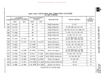
ENGINE SPECIFICATIONS CONT. R-6602 ENGINE MODELS
SD-220
SD-240
BD-269
RD-371
RD-406
RD-450
Number of cylinders . . • ,
Bore • . . . . . . . . . . ,
Stroke . • . • . • . . . • ,
Displacement (cu. in.).
Rated h.p. (A.M.A.) • • . . .
Brake h.p. (maximurn), •.
At r.p.m. . . . . . . . • ,
Brake h.p. (net) . . . . . , ,
At r.p.m. . . • • . . . . .
Torque maximum (lbs.ft.~
At r.p.m. . . . . . . . . .
Torque net (lbs. ft.) . . . .
At r.p.m. . . . . . . . • .
Maximum recommended
speed r.p.m. . . . . . . ,
Governed speed r.p.m. . .
Compression ratio . . . . ,
Firing order . . . . . , . . .
Crankcase refill capacity
(q ts.) . . • . . . • . . . ..
Weight, bare (lbs.) . . . . .
Weight, with standard
accessories (lbs.). . . .
CRANKSHAFT:
6
3-9/16"
3-11/16"
220.50
30.4
100,0
3600
90
3600
173.5
2000
167
1200
6
3-9/16 11
4-1/64"
240.30
30.4
108
3600
93
3400
191. 9
1400
186
1100
6
3-9/16 11
4-1/2"
269.10
30.4
100,5
3000
88,6
2800
222.0
1600
216.5
1000
6
4-3/8"
4-1/8"
372.06
45.9
143,8
3200
128
2850
282.5
1600
280.0
1000
6
4-3/8 11
4-1/2 11
405.89
45.9
154,2
3200
138
2750
319.0
1200
313.5
1000
6
4-3/8 11
5"
450.99
45.9
162,2
3000
146
2600
358.5
1200
354.0
1000
3600
3400
3000
6.5
153624
6,5
153624
6,3
153624
2850
6,3
153624
2750
6.3
153624
2600
6,2
153624
153624
7
607
7
607
7
781
9
937
9
942
9
948
16
1638
673
673
874
1047
1076
1082
1863
2.748"
2.749"
2.373" 2.374"
.0010"
,0040"
005" -. 0 13"
rear
interm.
through
2.748"
2.749"
2,373" 2.374"
.0010"
•0040"
.005"-,013"
rear
interm.
through
2.7005"
2.70 IS"
2.122" 2.123"
,0013"
,0043"
.0055"-,0135"
rear
3.2495"
3.2505"
2.751"
2.752"
,0013"
.0043"
,004"-.01211
rear
3.2495"
3,2505"
2.751"
2.752"
,0013"
,0043"
.004" -,012"
rear
3.249511 3.2505"
2,751"
2.752"
,0013" .0043"
.004"-.01211
rear
3.2491!
3,250"
2.999"
3,000"
,0022"
•0046"
,006"-.008 11
front
through
tocco
tocco
tocco
tocco
75-85
75-85
100-II 0
100-1I0
100-110
100-110
105-115
,
Main journal diamBter.
{
Crankpin diameter . . .
{
Bearing clearance . • .
Crankshaft end play ••
Thrus t taken by . . . . .
r
l
{
Hardening method. . . .
Main bearing bolt ten
sion (ft. Ibs.) . . . • .
CAMSHAFT:
Camshaft journal dia
meter
Front . . . . . . . . . . '
6
4-7/8 11
5-/38"
602.00
.
r
r
Z
tTl
3:
o
--l
o
:;0
--l
:;0
C
()
7\
(f)
tTl
:;0
<
n
tTl
3:
::t>
z
C
::t>
r
Ul
'U
(l)
n
{
Second . . • , . , , , . , {
2.109"
2,110"
2,089"
2.090"
2.109" 2.110"
2.089"
2.090"
1.811"
1.812"
1.577"
1.578"
2.109"
2.110"
2.089" 2.090"
2.109" 2.11 0"
2.089" .
2.090"
2,109" 2.11 011
2.089"
2.090"
2.1220"
2.1225"
2.1220"
2.1225"
~t'l
",,·Z
"dQ(l
,.,. ......
\I)
O'Q
(l)
""'Z
g t'l
,...UlUl
Donated by John & Susan Hansen - For Personal Use Only
'1jtllM
III '0
C/Q
ENGINE MODELS
SD-220
SD-240
BD-269
RD-372
RD-4.06
RD-450
CONT.
R-6602
(1)
Il>
Z
n 0
....1-<
N~Z
() M
III til
2.06.9" 2,070"
1.4995"
1.5005"
Third . • . . . . . . . , ,
Fourth . . . , . . . . . .
Fifth . . . . . , . • . , .
Camshaft bearing
{
clearance, . . . , . , .
Camshaft end play . , . {
Thrus t taken by . . . . . {
Camshaft gear backlash
i
CONNECTING RODS:
Connecting rod bearing {
end clearance . • . . .
Connecting rod bearing {
clearance. . . . . . . .
Connecting rod bolt nut
tension (ft. lbs.). , . .
2.069"
2.070"
1.4995"
1.5005"
2.069"
2.070"
1.4995"
1. 5005"
.. . . . . . . . . . . . . . . 0 "
"' ...... 1>"" ......
.. ............ "0.
.. .... " .... 0"""
0.00 ••••••
.0010"
• 0035"
.0020"
.0080"
Thrust
Flange
.0015"
(desired)
, 00 10"
.0035"
.0020"
.0080"
Thrus t
Flange
.0015"
(desired)
· 00 10"
.0035"
.0020"
.0080"
Thrust
Flange
,0015"
(desired)
.0010"
.0035 11
.0020" •0080"
Thrust
Flange
.0015"
(desired)
• 00 10"
.0035"
.0020"
•0080"
Thrust
Flange
.0015"
(desired)
• 00 I 0"
.0035"
.0020"
•0080"
Thrust
Flange
.0015"
(desired)
2.1220" 2.1225 11
2.1220" 2.1225"
2.1220"
2.1225"
.0015"
.0025"
.0050"
.0070"
Thrust
Flange
.0015"
(desired)
.0070"
• 0 13"
.0011"
.0011"
.0070" .013"
.0011"
.0032"
.0070"
.0130"
•0007"
.0032"
.0070"
.0130"
.0012"
.0037"
.0070"
.0130"
.0012"
.0031"
.0070"
.0130"
.0012" .0037"
.0060"
.0100"
.0012"
.0036"
:::0
--l
:::0
C
45-55
45-55
60 70
75-85
75-85
75-85
100-110
7\
..... " .........
2,069"
2.070 11
1.4995" 1.5005"
o
:::l
Ul
r;
C
z
(T1
s:
o--l
o
PISTONS:
()
en
[T1
Material . . • . . . . . . . {
Recommended piston
clearance:
PISTON PINS:
Length • • . . . • • . . . .
Diameter . . . . . . . • . {
Pin fit (room tempera
ture70 0 F.): .
r
Recom~ended clear {
ance in rod.· . • . • .
Recommended clear
ance in pis ton. . •. L
J
FEELER GAUGE RIBBON
CHECKING:
Width . . . . . . . . . . . .
Thickness . • . • . . . . .
Tension on scales (lbs.)
Desired tension (lbs.) .
c:
1.562"
1.563 "
1.499" 1.500"
"
2.069"
2.070"
1.4995" 1.5005"
aluminumalloy
aluminumalloy
aluminumalloy
alum.inum
'lHoy
aluminumalloy
aluminumalloy
aluminumalloy
:::0
<
.003
.003
.003
.003
.003
.003
()
[Tl
2.950"
.8748" .8750"
2.950"
.8748" .8750"
2.950"
.9192/1
• 91 94"
3.796 11
1.1089"
1.1091"
3.796"
1.1089"
1.1091"
3.796. '
1.1089" 1.1091"
1.4998" 1. 5000"
.0002"
.0004"
.0000"
.0002"
s:
»
z
c
»
r
.0002" .0004"
.0000"
.0002"
.0003"
• 0004"
.0000"
.0002"
.0005"
•0006"
.0000"
.0002"
.0005 11 .0006 11
.0000" .0002"
.0005"
•0006"
.0000" .000211
.0003" .0007"
• 000 1" - tight
. 000 111 -loos e
1/2"
,003"
6-18
12
1/2"
. 0 03"
6-18
12
1/2"
.003"
6-18
12
1/2"
.003"
6-18
12
1/2"
. 003 11
6-18
12
1/2"
. 003 11
6-18
12
1/2 11
• 005"
5-10
8
Donated by John & Susan Hansen - For Personal Use Only
ENGINE MODELS PISTON RINGS:
COlTIpression Rings:
Ntunber used on each
pis ton, •
Size. . . . • . .
{
Oil Rings:
Ntunber used on each
piston, . .
Size . . • . . .
Ring dialTIe ter
Ring Gap:
COlTIpression,
U-F1ex •. , , ••
Fit in Groove:COlTIpression - top, , { - 2nd &: 3rd • , , , . {
Oil Control - fourth • {
SD-220
SD-240
BD-269
RD-372
RD-406
RD-450
CONT.
R-6602
3
1-3/32 11
2-1/S"
3
1-3/32 11
2-1/S I1
3
1-3/3211
2_1/S II
3
1-3/32 11
2-1/S 11
3
1-3/32"
2-1/8"
3
4
1-3/32 11
2-1/8"
1
3/16"
3-9/16 11
1
3/16"
3-9/16"
1
3/16 11
3-9/1611
1
1
1
3/1611
4-3/8"
3/16"
4-3/8"
3/1611
4-3/8 11
. 0 16" -. 026"
,016" -.026"
,016" -,026"
,0025" ,0040"
.0015 '1 ,0030"
,0015 11 ,0035"
00025 '1 .004011
,0015 11 ,0030"
.0015 11 .00351 '
,0025"
,0040"
.0015"
.0030"
.0015"
.0035 11
r
1
r
z
(TJ
,025" -, 035
11
,0040 '1 00055"
.0020 '1 .0035"
,0015"
.0035"
,025" -.035"
.025"-.035"
.013" -,023"
,004011 ,0055"
,0020"
,0035"
,0015"
,0035 11
,0040"
,0055"
,0020"
.0035"
.001511 .0035"
,0055"
.0070"
,0025"
,0035"
.0015"
,0035"
.0015"
,0035"
Plain - fifth, , , 3:
~
o
:::0
-l
:::0
C
n
A
(f)
INTAKE VALVES:
StelTI dialTIeter •.
.372"
.372"
,342"
A34"
.434"
.434"
.4973 11
Angle of face ••.•
30°
3
45°
15°
15 0
15°
30°
Tappet clearance
,018"-.020" 1.018,,-.02011 I,OIS"-,020 11 I,OIS II -,02011 1,018"-,02011 1,018 11 -,020"
.020"
StelTI clearance in guide ,0015 1' -.0035" ,0015 1' -.0035" ,0015"-.0035" ,0015"-.0035" .0015"-.0035" .0015"-.0035" ,0008"-,0021"
Width of valve seat. . . 1/64"-3/64"
1/64"-3/64"
5/64"-7/64"
5/64"-7/64"
5/64" -7/6411
5/64"-7/64 11
1/16"-3/32"
(TJ
I
EXHAUST VALVES:
StelTI dialTIe ter, , .
Angle of fac e, , . .
Tappet clearance (hot).
StelTI clearance in guide
Width of valve seat .••
Slo-roto valve cap to s telTI clearance . .
VALVE TAPPET:
Clearance in block,
.370"
300
,018 1' -.020"
,002" -.004"
3/6411 -5/6411
.370"
30°
.018"-.020 11
.00211-.004"
3/6411 -5/64"
,341"
45°
.018 11 -.020"
• 002" -,004"
5/64"-7/641f
.434"
45°
.018"-.020"
. 002 11 -.00411
3/3211 -1
.434 11
45°
,018" -,020"
.002 11 -,004"
3/32"-1
,434"
45°
,018"-.020"
.002" -.004"
3/32"-1/8"
,494"
45°
.020"
,0035 11-.00511
5/64"-7/6411
.002"-,006 11
,002" -, 006'1
, 002" -, 006"
. 002" -.006" .001" -, 003"
.00 I" -. 003"
,001"-,003"
,0019" -.0002"
:::0
<
n
(TJ
3:
»z
c
»
r-
VI
. 00 1511 - . 003 11
,0015"-,003"
.0015"-.003"
'tl
(b
n
VALVE SPRINGS: Free 1enght:
Inner. Outer. , ..
~M
. . ·z
2-11-16"
2-11/16 11
2-33/6411
2-11/32
2-9/16 1 '
11
2-11/32
2-9/16"
11
2-11/32"
2-9/16"
11
2-3/4
2-13/16"
'U~o
P'<"'"H
OQ
(b
.....
Z
gM
WUlVl
Donated by John & Susan Hansen - For Personal Use Only
'ljClltr1
1Il'd
Z
OQ('I)Cl
('I)
H
C.
""t!!Z
n tr1
ENGINE MODELS
SD-220
SD-240
BD-269
RD-372
RD-406
RD-450
CONT.
R-6602
....~CIl
°
l::I
(Il
Length - valve open:
Inner . . . . . . . • . • •
Outer . • . . . . . • . • .
Lbs. pressure - valve
open:
Inner . • . . . . • • . . •
Outer . • . . . . . • . . .
VALVE ROCKER ARM
{
CLEARANCE IN SHAFT
VALVE TIMING:
Intake opens (before
T.D.C.) . . . • . . . • .
Intake closes (after
L.D.C.) . • • . . • . • .
Exhaus t opens (before
L.D.C.) . , . . . • . • .
Exhaus t closes (after
T.D.C.) . . . . . • . . •
Intake valve tiITling
clecking clearance •.
OIL PUMP;
Body gear end clear
ance • • • . . • . . . • .
PUITlP body to spiral
gear clearance . • . .
PUITlP shaft diaITleter . . {
PUITlP shaft clearance
in bore ••• , . • . • .
1.683"
1.683 11
•...•.....
..........
.•.•....•.
1.668"
1.503"
1. 7 06"
1.503"
1. 7 06"
1.503"
1.706"
1.750"
1. 7 50"
141-149
141-149
103-111
83-88
133-141
83-88
133-141
83-88
133-141
82-88
160-170
•...•...•.
...........
.0015"
• 0 04"
.0015"
•004"
.0015"
• 004"
,0015"
.004"
,0015"
• 004"
.0015" .004"
,0002" .0014"
10°
10°
5°
8°
8°
8°
12°
46°
46°
45°
52°
52°
52°
62°
48°
48°
40°
55°
• •••••• 0 ••
55°
55°
r;
C
z
(Tl
::::
o-1
o
:;;0
-1
:;;0
54°
C
8°
8°
10°
15°
15°
15°
20°
()
~
.023"
.023"
.023 1t
.023"
,023"
,023"
,020"
{j)
(Tl
:;;0
<
.0025" -,0055
...•......
.4885" .4890"
11
n
,0025" -.0055" .0025"-.0055" •0025" -.0055" • 0025" -.0055" • 0025" -,0055"
. ...•..••.
11
.4885
.4890"
-
.03125"
,4985"
.4992"
.03125"
.4985" .4990"
.03125"
.4985" .4990 fl
.03125"
.4985" .4990"
,005"
,005"
.005"
.005"
• 005"
.005"
OIL PRESSURES
MiniITlUIT1 (lbs.) . • • • .
At r.p.ITl• • . • • • . • .
MaxiITlUIT1 (lbs.) . • . • .
At r.p.ITl• . . • . • . • .
15-20
idling
40-45
1200 up
15-20
idling
40-45
1200 up
15-20
idling
40-45
1200 up
15-20
idling
40-45
1500 up
15-20
idling
40-45
1500 up
15-20
idling
40-45
1500 up
CYLINDER HEAD:
Cylinder head bolt
(ft. 1bs.) . . . . . • . • .
85-95
85-95
75-85
100-110
100-110
100-110
(Tl
$
:l>
z
c
:l>
r
100-110
Donated by John & Susan Hansen - For Personal Use Only
ENGINES
Specifications
Page 5
L-UNE MOTOR TRUCK SERVICE MANUAL
SILVER DIAMOND ENGINE SIZE AND
THREAD
NAME OF ASSEMBLY
RECOMMENDED
WRENCH TORQUE
LOAD, FT.-LB.
5/16
5/16
5/16
5/16
5/16
5/16
5/16
5/16
5/16
5/16
5/16
-
18
18
18
18
18
18
18
18
18
24
24
Generator s trap to generator . • . • . • . • . •
Water outlet • . • . • . • • • . • . • . • • • • . • •
Coil bracket to cylinder head • • . • • • . . • •
Fuel pump to crankcase • • • • . • . • . . . . . •
Oil pan to crankcase . • . • . . . • . . . . . . • •
Distributor adapter ·to crankcase • . . • . . • •
Oil pump cover to body • • . • • • • • . • . . . •
Vibration damper to pulley. •
. •.•..
Oil pump body to crankcas e • • • . • . •••••
Generator mounting • . . . . • . • • • . • . • . .
Coil mounting • . . • . • . • . • • • ' • • • . . • •
14
8
14
8
14
14
14
16
14
8
16
- 16 - 10 - 16 - 10 - 16 - 16 - 16 - 18 - 16 - 10 - 18 3/8
3/8
3/8
3/8
3/8
3/8
3/8
3/8
3/8
3/8
3/8
-
16
16
16
16
16
16
16
16
24
24
24
Manifold to cylinder head, • • . . . • • • . • . .
Engine support bracket to cr'ankcase • . • . .
Generator bracket to crankcase . • . • . . . •
Intake to exhaust manifold • • • • • • • . . • • •
Water pump to crankcase . . • . . . . . . . • . •
Cylinder head cover . . . . • . . • . • . • • • . .
Gear case cover to cr~nkcase . • . • . . . • . .
Camshaft thrus t flange . • . • • • • • . • . • . .
Connecting rod bolt• . . • • • • . • . • • • • • • •
Carburetor to manifold . . • • . • . • • • . • . .
Intake to exhaust manifold • • • • • • . • . . . •
25
25
25
25
25
25
25
25
45
23
23
-
30 30 30 30 30 30 30 30 55 28 28 5/16 - 24
Gear case cover to plate •.
7/16 - 14
7/16 - 14
7/16 - 20
Flywheel housing . . . • . • .
Oil pressure relief valve.
Flywheel to crankshaft . . . • . .
50 - 60
13 - 15
55 - 65
Starting motor . • . . . • • • . • • • . • • . . • . •
Cylinder head capscrew. . . • . • . • • • • • . .
Crankshaft bearing bolt . . . • . • . • . • . • • .
75 - 85
85 - 95
75 - 85
1/2 - 13
1/2 - 13
1/2 - 13
1 - 14
1 - 20
7/8 - 18
14 MM
14 MM
18 MM
18 MM
Starting crank nut. . . • . •
Camshaft lock nut. . . • . . .
Spark
Spark
Spark
Spark
Spark
plug
plug
plug
plug
plug
(in
(in
(in
(in
(in
PfUNTEO IN UNITED STATES OF AMERICA
cas t iron)
cas t iron)
aluminum)
cast iron)
aluminum)
•.
..
•.
•.••
...•
9 - 11
90 - 100
110 - 120
32
25
21
28
25
-
35
28
25
31
28
Donated by John & Susan Hansen - For Personal Use Only
ENGINES
Specifications
Page 6 L-UNE MOTOR TRUCK SERVICE MANUAL
SUPER BLUE DIAMOND ENGINE
SIZE AND
THREAD
NAME OF ASSEMBLY
RECOMMENDED WRENCH TORQUE LOAD, FT.-LB.
22 10 16 16 16 18 8 - 10 8 - 10 5/16
5/16
5/16
5/16
5/16
5/16
5/16
5/16
-
i8
18
18
18
18
24
24
24
Air cleaner to cylinder head• • • . • . • • • . .
Fuel PUInp to crankcase • • . • . . . • . • . • . •
Crankshaft rear oil seal, upper • . • . • . • • •
Distributor bracket to cylinder head •••.•
Oil pUInp cover to body • • • • • • • • . • • • . •
Vibration damper to pulley. • . . . • . . . . • •
Gear ca.se cover to plate • • . . • • . . • . • . •
Generator mounting • . . • . . . • • • . • . • .
18 8 14 14 14 16 -
3/8
3/8
3/8
3/8
3/8
3/8
3/8
3/8
3/8
3/8
3/8
-
16.
16
16
16
16
16
16
16
16
24
24
Manifold to cylinder head• • • . • • • • • • • • •
Oil pan to crankcas e . . • • . . . • • • . • . • . •
Generator bracket to crankcase . • . • • • . •
Oil pump body to crankcas e • . . • • . , .• ,'.
Water PUInp to cylinder head • • • • . • • • . .
Crankshaft rear oil seal, lo,wer • . . . • .
Gear case cover to crankcase• . . . . • . . . ,
Cam shaft thrus t flange . . . • • • . • • . . . . .
Star ting mo tor. • • • . • . • . . • • • . . • • • . .
Carburetor to manifold. • . •. • . . • . • • •
G ear cas e c over to pIa te . • • • . . . . • . . • •
25 25 25 25 25 25 25 25 25 23 -
. 9 - 11 7/16 - 14
7/16 - 20
7/16 - 20
7/16-20
Oil pressure relief valve • . • . . • . . • • • . .
C onnec ting rod bolt. . • . . .• . • . • . • . •.•
Intake to exhaus t manifold . • . • . • . • . • . •
Connecting rod bolt• . • . • . • . . . . . • . • . .
13
60
55
60
1/2 - 13
1/2 - 13
1/2 - 20
Flywheel housing . . . • . . . • • • . • • . . . . .
Cylinder head cap screw • • . . • • • . • . • • .
Flywheel to crankshaft . . . • . • . . . • . • .
75 - 85 75 - 85 90 - 100 9/16 - 12
9/16 - 12
1 - 20
7/8 - 18
14 MM
14MM
18 MM
18 MM
30 30 30 30 30 30 30 30 30 28 - -15 - 70 - 65 - 70 Crankshaft bearing capscrew . • . • . • • • .
Crankshaft bearing caps crew . • • • . • .
100 - no
100 - 110 Camshaft lock nut. . . • • • . • . • . • . • . • . •
110 - 120 Spark
Spark
Spark
Spark
Spark
plug
plug
plug
plug
plug
(in
(in
(in
(in
(in
cas t iron) • . . . • • • . • . • . •
cas t iron) • . • . • . . . • . . . •
alUIninUIn) • . . . • . • . • . • . •
cas t iron) ~ . •
. •......
alUIninUIn) • . • . • . • . . . . . •
32 25 21 28 25 -
35 28 25 31 28 Donated by John & Susan Hansen - For Personal Use Only
ENGINES
Specifications
Page 7
L-L1NE MOTOR TRUCK SERVICE MANUAL
SUPER RED DIAMOND ENGINE SIZE AND
THREAD
NAME OF ASSEMBLY
RECOMMENDED WRENCH TORQUE LOAD, FT.-LB. 5/16
5/16
5/16
5/16
5/16
-
18
18
18
24
24
Dis tributor bracket to cylinder head Crankshaft rear oil seal, upper • . . . Crankshaft rear oil seal, lower .. Generator mounting .. , •••••. Carbu.retor to manifold (Holley) 18
18
18
20
20
-
22
22
22
24
24
3/8
3/8
3/8
3/8
3/8
3/8
3/8
3/8
3/8
3/8
3/8
3/8
3/8
3/8
3/8
-
16
16
16
16
16
16
16
16
16
16
16
24
24
24
Starting motor mounting • . • .
Oil pump body to crankcase ••
Camshaft thrust washer . . . • .
Damper to pulley hub • . • . • . . • • . •
Fuel pump to crankcase• • • • . • . •
Rocker arm bracket to head ..•
Gear case to crankcase . . . . . . . • . •
Generator bracket to case . • . • . • . •
Water pump to cylinder head ••.•••••
Oil pan to crankcase . . . • . • . • . • . • . •
Oil filler. . . . . . . • • • . . . • . • . , . , . • . •
Gear case cover to crankcase plate . • . • • •
Carburetor to manifold (Zenith) •.
Gear case cover . . • • • . •
Manifold to cylinder head• . • .
25
25
25
30
25
25
25
25
25
25
25
25
23
23
23
-
30
30
30
35
30
30
30
30
30
30
30
30
28
28
30
7/16
7/16
7/16
7/16
-
20
20
20
20
Intake to exhaus t manifold ••. Intake to exhaus t manifold. , . . . • . • . • . • Connecting rod capscrew (place type). Carburetor to manifold. • • • . .
. •.•.• 55
55
75
40
-
65
65
85
45
1/2
1/2
1/2
1/2
1/2
-
13
13
13
13
13
Oil filter mounting. . • . • . . . •
. •.•.• Cylinder head capscrew, oil. •• . . • • • . • Cylinder head caps crew, long • • . . . • • • . • Cylinder. head caps crew, short • . • . • Flywheel housing to crankcase ••• 75 - 85 100-110 100 - 110 100-110 75 - 85 9/16
9/16
9/16
9/16
-
18
18
18
18
Crankshaft
Crankshaft
Crankshaft
Crankshaft
150 - 160
150 - 160
100-110
100 - 110
24
1 - 20
7/8 - 18
14 MM
14 MM
18 MM
18 MM
to flywheel. ••••. to flywheel •. bearing cap. bearing cap. Camshaft gear nut ••.• Spark
Spark
Spark
Spark
Spark
plug
plug
plug
plug
plug
(in
(in
(in
(in
(in
PRINTED IN UNfTEO STATES OF AMERICA
cast iron) ••• cast iron) •.• aluminum). cast iron) • aluminum). 110 - 120
32
25
21
28
25
-
35 28 25 31 28 Donated by John & Susan Hansen - For Personal Use Only
Donated by John & Susan Hansen - For Personal Use Only
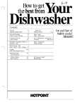
L-UNE MOTOR TRUCK SERVICE MANUAL
SILVER DIAMOND ENGINE
Fig. I - Silver Diamond Engine
PRINTED IN UNITED STATES Of" AM£RICA
ENGINES
Silver Diamond
Section A
Page 1
Donated by John & Susan Hansen - For Personal Use Only
ENGINES
Silver Diamond
Section A
Page 2
L-LINE MOTOR TRUCK SERVICE MANUAL
Gl
C
t:ft
C
UJ
-c
c
o
eta
o
L.. Gl >
.....o
~
Gl
.->
<0
C
o
.
t:ft
Donated by John & Susan Hansen - For Personal Use Only
L-UNE MOTOR TRUCK SERVICE MANUAL
ENGINES
Silver Diamond
Section A
Page 3
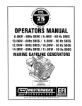
gine. The bayonnet type oil level gauge is
located on the left side of engine. The water
pump is located at the front of engine.
DESCRIPTION
General
The Model SD engine is a 4-cycle, 6-cylin
der-in-line, overhead-valve-type engine (Fig. 1
and Fig. 2).
The engine serial number is
stamped on a pad at the front on the right side
of crankcase just below the cylinder head. The
block does not have replaceable liners for the
cylinders. The detachable cylinder head con
tains all valves, valve guides, and springs.
The cylinders are numbered from front (fan
and timing gear end) to rear. Engine crank
shaft rotation is clockwise as viewed from the
front end of the vehicle. The intake and ex
haust manifolds, carburetor, starter, and gen
erator are located on the right side of engine.
The ignition coil, distributor, fuel pump, oil
pressure regulator, and breather are located
on the left side of engine. The oil fille r inlet
is located in the valve cover on the top of en-
Construction
1. The generator, fan, and water pump are
driven by a V-type belt from a driven pul
ley mounted on the front end of crankshaft.
The distributor, mounted at the left side
of engine, is driven by the camshaft through
the oil pump.
2. The exhaust and intake manifolds are bolted
to each other and to the right side of the
engine head. The intake manifold and the
exhaust manifold are each cast in one
piece.
3. A vibration damper is provided at the ,front
end of the crankshaft on the model SD-240
engine only.
e:i;J~~~~~~---- Cover capscrew
Rocker arm
shaft
Retainer
Lock----
1:. .- -
Spring ----....lIIl!!III!'!~1
Rocker arm
cover
Sleeve dowel
Cover gasket
.:-....---Valve guide
!;.!!!!!!;,..~--- Valve
'...!...._-- Valve seat
Push rod
E4f.---Seal ring
Connecting rod
A.21930
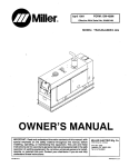
Fig. 3 - Sectional view through engine showing details of valve mechanism.
PRINl'EO IN UNITED STA"rEs OF AMERICA
Donated by John & Susan Hansen - For Personal Use Only
ENGINES
Silver Diamond
Section A Page 4
L-UNE MOTOR TRUCK SERVICE MANUAL
4. The cylinder block and crankcase are cast
in one piece, and carry the crankshaft
main bearings.
Water circulation pas
sages completely surround the cylinders
in the crankcase, and also provide coolant
to the cylinder head.
5. Oil is supplied under pressure by the oil
pump to the engine lubrication system.
Oil spray from the revolving cranksahft is
distributed to the cylinder walls, pistons,
and other moving parts inside the engine.
6. Exhaust valve seats are of alloy, and are
pressed into place (Fig. 3). These valve
seats lengthen the period between valve
reconditioning operations.
Valves and
valve seats are cooled by continuous cir
culation of water through the cylinder
head.
7, The detachable cylinder head is bolted to
the crankcase, and a gastight and water
tight seal is maintained by means of a
gasket.
8. The crankshaft is a drop forging of heat
treated steel. It is counterweighted, bal
anced both statically and dynamically, and
ground to close limits. The shaft is
mounted in four precision-type replace
able shell bearings, the number three
bearing taking up the thrust.
9. The pistons are made of an aluminum al
loy, are cam ground, and are fitted with
three compression rings and one oil con
trol ring. The full-floating type piston
pins are held in place in the pistons, at
the ends of the pins, by snap rings.
10. The camshaft is machined from a solid
drop forging and mounted in four special
replaceable bearings.
11. The flywheel is bolted and doweled to the
crankshaft flange. The timing mark is lo
cated on the flywheel.
Fig.
ij -
Removing Silver Diamond Engine.
2. Disconnect upper and lower radiator hose
connections.
3. Disconnect engine circuit wiring.
This
includes coil wire, starter cable, engine
ground strap, and instrument sender unit
wires.
4. Disconnect fuel line at fuel pump. Discon
nect throttle control linkage at left side of
engine and remove choke at carburetor.
5. Disconnect clutch linkage at bell housing.
6. Remove engine rear mounting bolts from
both sides of engine support pads.
7. Remove engine front mounting bolts from
support bracket; these are the bolts at the
front crossmember. NOTE:
The engine
front support bracket is removed with the
engine.
8. Remove radiator mounting bolts, and lift
out radiator support and core assembly.
9. Disconnect engine exhaust pipe at mani
fold.
ENGINE REMOVAL
ENGINE DISASSEMBLY
The engine, with transmission removed,
can be lifted from chassis, without disturbing
the fender and grille assembly by using a suit
able chain sling and a floor crane (Fig. 4), Dis
connect the following electrical circuits, hose
connections, and various units as outlined:
Install the engine in a suitable rotating
engine overhaul stand.
NOTE: Many of the
disassembly operations can be performed with
the engine in the chassis. However, the fol
lowing disassembly outline is performed with
the engine removed from the chassis to clear
ly illustrate each of the units. Except where
indicated, no attempt has been made to pre
scribe a particular sequence for removing the
various units, since some can be readily re
moved with the engine in the chassis. The ex
tent of the service required on a particular
unit will govern the necessity for its removal.
1. Drain engine oil pan. Drain all coolant
from engine cooling system by opening the
drain cock on side of engine as well as the
radiator drain cock.
Donated by John & Susan Hansen - For Personal Use Only
ENGINES
Silver Diamond
Section A
Page 5
L-LINE MOTOR TRUCK SERVICE MANUAL
Removing Rocker Arms
The following steps are to be followed when
removing the rocker-arm cover and rocker
arm assembly. (Carburetor and air cleaner
previously removed):
1. Remove three capscrews from rocker-arm
cover. Remove air cleaner line and re
move cover (Fig. 5).
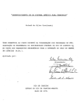
Rocker-Arm and Valve Mechanism Disassembly 1. The rocker-arm assembly is composed of
front and rear shafts joined at the center,
on which are mounted twelve rocker arms
and six tension springs (Fig. 8). The
shafts are mounted in seven brackets, and
are prevented from turning at the two end
brackets by slots in the shaft into which
the cylinder-head bolts fit.
J7
~"mW'
~iitIJI,tr.>itA~,~
. . "'. · , . .
Rook" -
...
-.~~v~v
Sleeve dowel
Brackets
Tension springs
A-21909
Fig. 8
Fig. 5
2.
Remove capscrews from shaft brackets
(Fig. 6).
Shaft brackets
2. Number two, four and six rocker-arm
brackets have sleeve dowels which keep
the rocker-arm assembly aligned.
3. These sleeve dowels measure approxi
mately 5/81! in diameter, I" long, and 1/32"
wall.
4. The three hold-down brackets are reamed,
from the bottom side (Fig. 9) so that the
sleeve dowels willfit .0005"-.0035" tight in
brackets. About one-half inch of dowel is
in the bracket. The remaining half of
dowel is fitted .0025 11-.0055" loose in the
head. When removing rocker-arm assem
bly the dowels will remain in hold-down
brackets.
F j g. 6
3. Remove rocker-arm assembly as a unit
(Fig. 7).
Rocker arm assembly
Sleeve dowel
Fig. 9 - Oetai Is
of sleeve
A-21938
dowel
located in
bracket.
5. Separate the shafts and slide rocker arms,
springs, and brackets from shafts.
6. Clean all parts in a solvent cleaning fluid,
being careful to clean all ac(mmulated
sludge and carbon deposits from oil holes
and slots.
PRINTED IN UNITED STATES OF' AMERICA
Donated by John & Susan Hansen - For Personal Use Only
ENGINES
Silver Diamond
Section A
Page 6
L-L1NE MOTOR TRUCK SERVICE MANUAL
Rocker Arm Inspection H - - - Press
ram
Carefully inspect all parts for defects and wear: 1. Inspect rocker-arm shaft expans ion plugs.
Check ona surface plate for signs of bend ing, check for wear from rocker arms. If a shaft is bent or shows perceptible wear, it must be replaced. 2. Inspect rocker-arm adjusting screws for
wear at contact surface and for thread
wear. Replace worn screws. Check rock er-arm bushings for wear. If clearance
on shaft exceeds .004", replace bushings.
Inspect valve stern contact pad surface of
rocker arms, and resurface if wear is
perceptible. a<o!;'--- Bushing
installing tool
3. Inspect tension springs for breakage or loss of tension. Replace defective springs.
Remove valve lifter rods. Fig. 11- Installing new rocker arm bushing. Re-bushing Rocker Arms
With properly fitting adapter, press old
rocker-arm bushing from rocker arm (Fig.
10). Place new rocker-arm bushing in posi
tion. Align oil hole in bushing with oil hole in
rocker arm, which is located 23 0 from top of
rocker arm toward rocker-arm adjusting nut.
Use an installing tool and press new bushing
into rocker arm (Fig. 11). Burnish bushing
into place in the rocker arm (Fig. 12), then
ream rocker-arm bushing to provide ,0015 11
.004 11 clearance.
....:'----Burnishing tool
Fig. 12 - Use SE-93 I Burnishing bar.
Cylinder Head and Valves
, . . - - Press ram . . . , - - - - - Bushing removing tool The following instructions are to be fol
lowed when reconditioning cylinder head and
gasket. Remove push rods, remove cylinder
head bolts and lift off cylinder head and gasket
(Fig. 13). Place cylinder head on bench.
Spark plugs
Rocker arm
-
Press plate
Fig. 10 - Use SE-1036-1 Bushing Removing Tool
when removing the rocker arm bushing. Support
the rocker arm on the SE-1033 support block.
Select a bole in the support block to properly
support the rocker arm at the same time permit
the bushing to clear the support block when
being removed. Use the support block when in
stall ing and burnishing the new bushing.
Fig. 13
Donated by John & Susan Hansen - For Personal Use Only
L-UNE MOTOR TRUCK SERVICE MANUAL
1. Compress valve spring with a valve com
pressor and remove valve spring retainer
locks (Fig. 14). Remove retainer. Re
move valve spring and damper and separ
ate valve spring damper from valve spring.
Note that valve springs can be installed
with either end toward the cylinder head.
Remove all valve springs as outlined, and
remove valve spring damper from each
spring (Fig. 15).
ENGINES
Silver Diamond
Section A
Page 7
2. Inspect exhaust valve seat
for loose
ness and inspect for exce
width of
valve seat surface. 1£ rings are loose, re
place. 1£ a seat has been previously ground
to such extent that it cannot be narrowed
from top to bring to proper position near
center of valve face, the
must be re
places.
Inspection of Valve Guides, Valve Springs,
and Valves
1. Clean valve guides with a suitable clean
ing tool. Check each valve guide with a
tlGo and No-Go" gauge, if available; other
wise, use a new valve to check fit. 1£ 'IINo_
Go" portion of gauge enters, the guide must
be replaced. Recommended valve stem to
valve guide clearance is from .0015 11 to
.0035 11 for intake valves, and from .0021t'to
.004" for exhaust valves. Clearance
in
excess of .006" for intake valves or .008"
for exhaust valves, require guide replace
ment. Valve guides are reamed to .3743"
.3758 11 after assembly in cylinder head.
2. Test valve springs with damper in posi
tion. Test tension of each valve spring at
valve open length with a valve-spring test
er (Fig. 16).
Check valve springs at
1-11/16 11 length, and replace if pressure
is less than 149 Ibs.
Fig. IIj.
Valve spring
Damper A.21939
Fig. 15 - Dampers are used at all the valves.
Assemble damper, spring and retainer as shown.
2. Invert cylinder head. Remove all valves
from their valve guides and from the head.
3. Scrape all carbon from cylinder-head
combustion chamber, and clean any gasket
rna terial from surface of head. Clean the
head using steam cleaning or other suit
able cleaning equipment
4. Clean all carbon deposits from valve heads
and valve stems with a wire brush. Wash
all valve springs and retainers in clean
ing solvent.
Inspection of Cylinder Head
1. Inspect cylinder head visually for signs of
cracks or sand holes. If found defective,
weld or replace head ..
PAINT£O IN UNITED STAT£$ Of' .... ERICA
~----Valve
spring
1Ii~"-~r---T--- Scale (pounds)
A.21890
Fig. 16 - Use SE-1565 Valve spring testing tool
or similar tool to check spring tension.
3. Inspect each valve for warpage, :Cor severe
ly burned condition, and for excessive
grinding on the valve head. Inspect valve
stem for scuff marks or perceptible wear.
Donated by John & Susan Hansen - For Personal Use Only
ENGINES
Silver Diamond
Section A
Page 8
L-UNE MOTOR TRUCK SERVICE MANUAL
Inspect valve stem end for wear at contact
surface with valve rocker arm. If valve
is warped, excessively burned, or has been
previously ground to extent that valve head
is thin at edge. replace valve; otherwise,
valve can be reconditioned and reinstalled.
Repair of Cylinder Head
1. If cylinder head has to be resurfaced, re
move only enough material to true-up
surface.
2. If any valve guide shows excess clearance
or"" out-of-round condition, press guide
from cylinder head with a special remov
ing tool (Fig. 17). Install new guide, and
press into cylinder head until approxi
mately 1-11411 remains above the top sur
face of cylinder head (Fig. 18).
Check
valve guides after installation to .3758 1t to
. 3743 11 with "Go and No-Go!! gauge. Ream
valve guides to .3743 11 -.3758't after assem
bly in cylinder head.
3. If an inspection has indicated the necessity,
replace the valve seat.
4. Grind the valve seats in cylinder head to
30 0 on exhaust and 30 0 on intake.
Reconditioning Valves and Seats
One of the principal difficulties experienced
in reconditioning valves is obtaining nearly
identical angles on the valve seat and valve
face.
The importance of these angles in the
grinding operation cannot be overemphasized,
because it is impossible to produce a flat or
square seat by lapping.
The grinding stones on both the valve
refacing machine and valve-seat grinder should
Press ram
be dressed before starting a reconditioning job.
You will be unable to determine how closely
the angle of the seat will match the valve face
until the valve and seat have been ground and a
check made with a very light tint of Prussian
blue. If a full seat-width contact around the
entire circle of seated valve is not shown, the
angles do not match. It will then be necessary
to redress the valve seat grinding stones,
changing the angle sufficiently to correct the
error. The correction should be made on the
valve seat, and not Q.!! the valve.
No more
material should be removed from the valve
face than is necessary to true it up and remove
the burned or pitted portion. New valves should
not be refaced, but should be checked for true
ness. When a satisfactory match of valve seat
and valve face angles has been obtained, the
adjustment of both the valve refacer and the
seat grinder should be locked in position, in
order to eliminate this trial-by-error method
on additional valves having the same angle .
Valve Seats
The primary purpose of a valve seat is to
seal the combustion chamber against pressure
losses and to provide a path to dissipate the
heat accumulated in the valve head so as to
prevent burning of the seat and warping of the
valve head.
The location of the valve seat on the valve
face and its width controls the amount of valve
head that protrudes into the combustion cham
ber. It is obvious that the greater the expo
sure within the combustion chamber, the higher
the valve temperature; or in other words, the
more heat it will collect. High valve tempera
tures and poor heat dissipation also produce
excessive valve stern temperatures and hasten
the accumulation of carbon on the stern, caus
ing them to stick in the guides.
Press ram
-A:
Valve guide remover -~..
JIll
j
f
Valve guide
Fig. 17 - Use SE-I722 Valve stem guide tool.
I
Valve guide replacer
V':SDd" "'ad
I
Fig. 18 - Using SE-1723 Guide replacer.
gu i de down unti Ito(),I" bottoms on head.
Push
Donated by John & Susan Hansen - For Personal Use Only
L-LINE MOTOR TRUCK SERVICE MANUAL
Valve Seat Widths
In general, the width of exhaust seat should
range between the average and maximum spec
ifications and the intake seats between the
minimum and average specifications. The in
take seats may be narrower than the exhaust
because they are usually larger in diameter,
thus providing a total seat area approximately
equal to smaller exhaust valve with the wider
seat. Also the less severe heat conditions do
not require as large a seat area for heat dissi
pation purposes.
There are also objections to an excessive
ly wide seat, a few of which are as follows:
1. In city or light delivery service a wide
seat collects carbon and particles of dirt
that will produce variations or loss of
compression, resulting in poor idle and
possibly a loss of general performance
and economy.
2. A wide seat in severe service operating in
the presence of dirt or an excess of car
bon will produce a badly pitted seat which
may be just as detrimental to valve life as
a too narrow seat. Under these conditions
a seat width to the minimum limit would
possible be better; however, the source of
trouble (which is the dirt and excessive
carbon) should be eliminated, making it
possible to retain the wider seat.
Valve Seat Inserts
ENGINES
Silver Diamond
Section A
Page 9
face, and tap valve lightly to its sea,t.
NOTE: This is merely for test and proof
of re suIts of refacing and re seating ope r
ations. A poor grinding job cannot be cor
rected by valve lapping.
5. Inspect each valve coated with blue for
seat position. The seat should be at the
approximate center of valve face, 3/64"
5/64 11 wide for exhaust, and 1/64 1t -3/64"
wide for intake (Fig. 19).
Valve guide --~
Exhaust valve -;--r;;;.-
~5;:;;t--lntake
valve
A-:21889
Fig. 19 - Diagram showing valve installation.
Valve Assembly
1. Wipe valve faces and valve seats with a
cleaning solvent to remove all dirt or for
eign material. Coat valve sterns and valve
faces with oil, and install valves in same
seats to which they were checked.
Necessity for replacing valve seat inserts
should be very rare; however, if a replace
ment is made it is important that new inserts
be peened securely in place, using either in
sert peening tool or a dull-pointed chisel,
1/411 wide, to peen cylinder head metal over
outer edge of valve seat insert.
2. Install valve springs with dampers. Com
press valve springs with a valve spring
compressor, and install valve spring re
tainers and retainer locks. Be sure that
retainers and locks are correctly seated.
Valve
available.
When overhauling engine with head and pan
removed, the following procedures are recom
mended:
seat
insert
installing
tools
are
Valve seat inserts supplied for service
are standard size and .030" oversize which
permits a tight fit in cylinder head.
Repair of Valves
1. True-up the ends of valve stern against
face of grinder. Remove only enough ma
terial to true the surface.
2. Reface exhaust valves to 30 0 • The valve
face and valve seat angle must be identi
cal.
3. Reface intake valves to 30 0
seat being the same.
with valve
4. Place valves in cylinder head. Place a
thin coat of Prussian blue on each valve
PRINTED IN UNITF"O STATe'S 0':-- AM£RICA
1. Remove front motor to frame bracket by
removing two nuts on top side (Fig. 20).
Remove fan drive pulley nut and washer
from end of crankshaft. Install puller and
remove crankshaft fan drive pulley from
crankshaft (Fig. 21). Remove 4 capscrews
holding motor mounting bracket to block
(Fig. 22).
2. Remove nuts and capscrews from engine
gear case cover, remove gear case cover
and gasket. Remove crankshaft oil slinger
from end of shaft (Fig. 23).
3. Remove two self-locking capscrews from
camshaft retainer thrust flange plate,
working through two holes in camshaft
gear (Fig. 24). Pull camshaft and gear
assembly from cylinder block. Remove
Donated by John & Susan Hansen - For Personal Use Only
ENGINES
Silver DiaInond
Section A
Page 10
L-UNE MOTOR TRUCK SERVICE MANUAL
two capscrews holding the gear case cover
J?late to block; reInove plate and gasket
(Fig. 25). ReInove crankshaft tiIning gear,
using a special gear puller (Fig. 26).
(NOTE: Lubricate puller screw to pre
vent daInage to screw threads).
Turn engine in the overhaul stand and pro
ceed with disasseInbly as follows:
4. Each connecting rod is nUInbered as to its
position in the engine and these nUInbers
are located on the caInshaft side of the
engine. ReInove self-locking capscrews
froIn connecting-rod cap and reInove cap.
Push connecting-rod and piston asseInbly
...
toward top of block, but first reInove ridge
froIn top of cylinder wall, if any. Lift
piston and connecting-rod asseInbly froIn
top of cylinder block (Fig. 27). Replace
cap on connecting rod. ReInove the re
Inaining pistons, following the saIne pro
cedure.
Note that the connecting-rod caps are
aligned with the rods by Ineans of tongue
and groove construction (Fig. 28).
....... Front motor
mounting support
Crankshaft
vibration damper
A·.21940
Fig. 23 - Gear case cover
ing gear details.
removed showing tim
Fig. 20
-_I..,.,. .__-,---
Fig,21
Fig. 2~ - Timing gear timing marks and camshaft
thrust plate details.
Capscrews
Fig. 22
A.21944
Fig. 25 - Camshaft and cover plate removal.
Donated by John & Susan Hansen - For Personal Use Only
L-UNE MOTOR TRUCK SERVICE MANUAL
ENGINES
Silver Diamond
Section A
Page 11
Crankshaft timing gear
A·21936
Fig. 26 - Crankshaft gear puller SE-1715 is
installed with puller plates in position shown.
Lubricate puller screw thoroughly.
Fig. 29 - Use SE-1719 Bearing
remove rear main bearing cap.
cap
puller
to
6. With crankshaft securely clamped in vise,
remove the six self-locking capscrews
holding flywheel to crankshaft (Fig. 30).
Tap flywheel with a soft hammer to loosen
it from crankshaft; remove flywheel with
ring gear assembly.
Fig. 27 - Remove
cyl inder block.
piston
and
rod
from top of
Fig. 30 - Remove self locking capscrews to
move f I ywhee I •
Tongue
7. A-21924
Fig. 28 - Connecting rod caps are al igned by
means of tongue and groove construction.
5. The crankshaft bearing caps are numbered
to identify thei r position and they must be
reinstalled in their respective positions.
Remove self-locking capscrews from each
bearing cap. Remove all crankshaft main
bearing caps. NOTE: To remove the rear,
or No.4, main bearing cap, a puller is re
quired (Fig. 29). After all caps have been
removed, lift crankshaft straight up and
out of cylinder block, and place in a vise
equipped with soft jaws.
PRINTED IN UNITED STATES OF" AMERICA
re
Remove six capscrews and lockwashers
from engine flywheel housing. Drive out
the two engine block dowels, remove fly
wheel housing.
8. Remove fuel pump, starter, oil pressure
regulator valve assembly,
distributor,
generator, oil gauge, coil, and all "freeze
plugs" in block. (NOTE: Removal of the
''freeze plugs" or core hole plugs is only
necessary when it is determined that the
condition of the water passages in the
block warrant a thorough cleaning, or the
plugs appear to be leaking.) Clean inside
and outside of block with a solvent cleaner
or stearn. Install core plugs using SE-l 725
Adapter and SE-l58l-lB Handle.
Donated by John & Susan Hansen - For Personal Use Only
ENGINES
Silver Diamond
Section A
Page 12
L-UNE MOTOR TRUCK SERVICE MANUAL
Water Pump Removal and Overhaul
The water pump is of the centrifugal pack
less type (Fig. 31). It is bolted to the front end
of the engine and is driven by the fan pulley.
It requires no external adjustment. The bear
ing is of the sealed lubricated type and does
not require added lubrication at any time. The
water pump is driven by a V -belt on the fan
pulley. The pump, by means of centrifugal
force developed by the impeller rotation, draws
water up from the lower part of the radiator
into the water passages in the cylinder block
and cylinder head.
The water circulates
through the cylinder block and then out through
the thermostat housing into the radiator upper
tank.
3. Remove three screws from back cover
plate. Remove plate and gasket from pump
body (Fig. 33).
Fig. 33
4. Remove snap ring from front of water
pump shaft bearing (Fig. 34). Support the
water pump on an arbor press and push
shaft and bearing out, as one assembly
(Fig. 35).
L22111
Fig. 31 - Sectional view of water pump.
Water Pump Disassembly
1. Remove four capscrews and lockwashers
holding fan to hub. Remove fan blade as
sembly from hub.
2. Remove four mounting capscrews from
water pump (Fig. 32). Remove water pump
from front end of cylinder head.
Fig. 311
......- - Press ram
Impeller
,.....: - - - - - Adapter
A-21905
Fi g. 32
F i9' 35
Donated by John & Susan Hansen - For Personal Use Only
L-UNE MOTOR TRUCK SERVICE MANUAL
5. Place shaft assembly in press and press
fan hub from shaft (Fig. 36). Donotattempt
to remove bearing or slinger, as they are
factory installed on the shaft in the proper
location.
6. Remove seal from housing through back
side of pump. Use a drift, and carefully
drive seal from the pump body.
ENGINES
Silver Diamond
Section A
13
4. Inspect pump shaft bearing for wear.
If
worn, replace bearing.
5. Examine shaft for wear and
replace if
needed.
Water Pump Assembly
1. Press fan hub on shaft with the smaller
diameter of the hub to the front (Fig. 37).
Water Pump Cleaning and Inspection
2. Install shaft in housing from front end by
Before reassembling water pump, the fol
lowing should be checked:
pressing shaft, bearing, slinger, and fan
hub in as one unit (Fig. 38).
1. Clean all parts by steam or cleaning sol
vent.
3. Install snap
(Fig. 39).
2. Examine seal for wear or damage and re
place parts as necessary. Use special tool
when installing seal. Use a new seal when
rebuilding the pump since the old seal may
have been damaged upon removal.
4. Mount assembly in press. Press impeller
on rear end of shaft. Place a straight edge
across the back of the water pump housing
and check the clearance between the straight
edge and impeller. There should be about
.025 11 clearance (Fig. 40).
in place behind fan' hub
3. Examine pump impeller seat seal surface,
if face of surface is scored, it must be re
surfaced or replaced to prevent leakage.
Press ram
Fan hub - ....._r:':1
Bearing - - - J l....:;
Pump
~---hou8ing
Fig, 36
A-21947
Small hub end -
Fig. 38
.........
Fan hub
Large bub end Water pump shaft - ....... bearing
14-21492
Fi g. 37
PRtNTED IN UNITED STATES OF" AMERICA
Fig. 39
Donated by John & Susan Hansen - For Personal Use Only
ENGINES
Silver Diamond
Section A
Page 14
L-UNE MOTOR TRUCK SERVICE MANUAL
Fi.g.
Fig.
~o
5. Install cover plate with new gasket, and
mount fan blades.
Intake and Exhaust Manifolds
When disassembling and assembling the
manifolds, the following procedures are used:
1. After removing the eight capscrews from
head and three bolts from exhaust flange,
remove both intake and exhaust manifolds
as a unit (Fig. 41). NOTE: Let manifolds
cool before starting above operations.
2. To separate the two manifolds, remove
the two outside capscrews and two inside
nuts from the center of manifolds (Fig. 42).
~2
2. If vacuum is needed to operate any unit
within the truck, a threaded inlet is pro
vided in the manifold for such purposes.
Exhaust Manifold
1. The exhaust manifold consists of four out
lets. The two end outlets remove burned
gases from the No. 1 and No.6 cylinders,
while the two center outlets remove burned
gases from Nos. 2, 3, 4 and 5 cylinders.
2. Located in the exhaust manifold, in the
center, is the manifold heat control unit
(Fig. 43).
Exhaust pipe flange --II";
3. The intake and exhaust manifolds are each
of one piece construction, requiring no
disassembly after separation.
Heat control valve
Fig.
Intake Manifold
1. The intake manifold consists of three out
lets, each supplying fuel to two cylinders.
Two studs are located on the top for car
buretor mounting.
~3
3. The purpose of the heat control unit is to
keep the intake manifold warm enough to
vaporize the fuel mixture as completely
as possible. The heat control is automatic
in operation, being controlled by a coiled
thermostatic spring.
A counterweight,
under spring tension, is mounted on the
heat control valve shaft and this counter
weight operates with the spring to close
and operate the heat control valve.
Donated by John & Susan Hansen - For Personal Use Only
L-UNE MOTOR TRUCK SERVICE MANUAL
ENGINES
Silver Diamond
Section A
Page 15
4. Should the valve hold too much heat, the
engine is likely to detonate or lping!1 when
engine is accelerated. If valve opens too
early, not enough heat is retained in the
manifold, resulting in a slow warm-up. If
the thermostatic spring becomes discon
nected, the whole heat control system will
be upset.
5. Should the shaft of the heat control become
stuck, tapping it with a hammer and work
ing the valve back and forth by hand usually
frees it. An application of penetrating oil
will help the process of freeing a sticking
heat valve.
Gaskets _ _--litO""
Oil pump base - - - - -.....t!";'
A-2J563
Manifold Inspection
Fi g. q5
Inspect intake and exhaust manifolds visu
ally for cracks or breakage. Place manifolds
on surface plate and check for warpage. If
cracked or broken, replace or weld. If slightly
warped, true-up on surface grinder but replace
if warpage is extreme.
Manifold Assembly
Place new gasket between the intake and
exhaust manifolds and install two capscrews
and two nuts. Mount manifolds together loose
ly before installing on engine. This will assure
proper alignment of the units with each other
and with the engine cylinder head.
Idler gear
Oil Pump Removal and Overhaul
A-2IS6"
Fig. q6
After oil pump has been removed, the fol
lowing steps are to be used for disassembly:
1. Remove cotter pin holding float to oil
pump (Fig. 44). Remove float from pump.
Remove two capscrews holding pump in
block. Remove oil pump.
Spiral gear
Fi g. q7
Fig. qq
2. Remove four capscrews and lockwashers
from oil pump cover plate. Then lift cover
and gasket from oil pump body (Fig. 45).
3. Lift out oil pump idler gear from idler
gear shaft (Fig. 46).
PRIN'r£O IN UNITED STATES OF' "MERICA
4. Support oil pump shaft to prevent bending
shaft, and using a small punch, drive out
spiral gear pin from oil pu:rnp spiral gear
(Fig. 47).
5. Place two support plates under spiral gear
in press, and press oil pu:rnp drive shaft
out of pump spiral gear (Fig. 48). Remove
Woodruff key.
Donated by John & Susan Hansen - For Personal Use Only
ENGINES
Silver Diamond
Section A
Page 16
L-LINE MOTOR TRUCK SERVICE MANUAL
Oil Pump Assembly
Fig. ~8 - Use SE-I~99 Oil pump support plate or
other suitable support when pressing shaft from
gear.
Pump body
The following instructions are to be fol
lowed for reassembly:
1. Install new Woodruff key on body end of
drive shaft.
2. Place in press and press body gear on
drive shaft. The end of the shaft can be
from flush to .030 11 below the level of gear
face.
3. Insert oil pump drive shaft and body gear
into oil pump body.
4. Install new Woodruff key in spiral gear end
of drive shaft and press on spiral drive
gear. Make sure that spiral gear hub is
down. Install new spiral gear pin in place.
5. Install idler gear on idler gear shaft. In
stall gaskets, oil pump body cover. four
capscrews. and lockwashers.
6. Check oil pump body gear end clearance
by using a dial indicator (Fig. 50). If end
clearance is less than .0025" add one gas
ket that measures not more than .003f! in
thickness. If end clearance is in excess
of ,0055 11 remove one gasket of not more
than ,003" in thickness. Body gear end
clearance should measure between ,0025 11
and .0055",
7. Inse rt oil pump float in oil pump, line up
cotter pin holes, install new cotter pin.
and fasten securely.
Body gear - -.....i..'\;!
A-21935
Fig.
Dial
indicator
~9
6. Remove body gear and drive shaft from oil
pump body (Fig. 49).
7. Press pump body gear from shaft and re
move Woodruff key.
8. Wash all parts in a cleaning solvent.
~B....-- Spiral gear
Oil Pump Inspection
Check the fallowing parts carefully:
1. Check oil pump drive shaft for wear at
points of contact with body.
If shaft is
worn or bent, it should be replaced.
2. The standard measurement of oil pump
shaft is .4885"-.4890". The shaft should
be concentric and straight through its en
tire length within .004 11 indicator reading.
3. Check oil pump body for warpage, damage.
and wear. Replace if body is warped or
cracked, or if shaft bore is worn so that
clearance between shaft and bore is in ex
cess of ,005!!,
The oil pump body shaft
bore measures .490 11 ,
4. Inspect oil pump gears, and replace if
wear is perceptible.
114---
Drive shaft
Oil pump - - - - - \ I.... body A-2J565
Fig. 50 - Checking end clearance of pump
and body gear.
shaft
Donated by John & Susan Hansen - For Personal Use Only
L-LINE MOTOR TRUCK SERVICE MANUAL
DISASSEMBLY, CLEANING, INSPECTION, REPAIR, AND ASSEMBLY OF SUBASSEMBLIES Cleaning the Cylinder Block
1. ENGINES
Silver Diamond
Section A
Page 17
Replacing Camshaft Bushings
1. If camshaft bearing replacement is neces
sary' remove and install new bushings
with special camshaft bearing installation
tool (Fig. 52). No reaming is required.
Remove all old gasketmaterialirom block.
Clean both inside and outside of block with
steam or cleaning solvent. Remove all
dirty oil, sludge, scale, and carbon from
cylinder block. Check core plugs for in
dication of leakage. Remove and replace
plugs that show signs of leaking, or rust
ing through. Use installing tool for core
plug replacement (Fig. 51).
Bushing arbors
Camshaft bushings
A-22r49
Fig, 52 -SE-172Q Camshaft bushing installation.
Showing tool in position.
Connecting-Rod and Piston
1. Fig. 51 - Installing core plug using SE-1725
Install ing tool with SE-1581-B handle.
Remove piston-pin retainers from each
pis ton, and remove pis ton rings from pis
ton ring grooves.
2. Heat piston in boiling water or piston
er. Place piston in piston vise, and
pin-driving tool, drive pis ton pin
piston and connecting rod (Fig. 53).
piston pin is removed, lift piston
connecting rod.
heat
using
from
After
from
Cylinder Block Inspection
1. Inspect cylinder walls for cracks.
Weld
the cracks or replace block if necessary.
\~
~
.,
;
..• '.".'.'..'.
"
2. Check top surface for trueness with a
straight-edge. Test by attempting to in
sert a .012" feeler gauge ribbon between
the straight-edge and the cylinder block.
If this is possible, either surface or re
place the cylinder block.
3. Inspect camshaft bearings for damaged or
scored condition, and inspect for wear.
Replace if damaged or if worn beyond
clearance limit of .0 061!.
4. Measure
cylinder walls with an inside
reading micrometer to determine taper,
out-of-round, or worn condition.
The
measurements must be made not only at
top of the cylinder bore, just below ring
groove, but at several places around the
inside circumference of the bore. Bore
should be checked at the bottom, below
ring wear surface, to determine the amount
of taper. Rebore if worn beyond .008"
clearance.
PRINTEO IN UNITED STATES OF AMERICA
A·22205
Fig, 53 - Use suitable piston vise to hold pis
ton and drive piston pin out using SE-1263. Use
soft (bronze or brass) hammer when driving to
prevent damage to tools..
Donated by John & Susan Hansen - For Personal Use Only
ENGINES
Silver DiaInond
Section A Page 18
3. 4. L-UNE MOTOR TRUCK SERVICE MANUAL
Wash allparts ina cleaning solvent. CAU
TION: Do not use a caustic solution for
alUnlinUnl pistons. Clean the carbon froIn
pis ton ring grooves with a broken ring or
ring groove cleaner.
Press ram
--~
Adapter
Inspect connecting rods, caps, and bearing
shells. All connecting-rod bearings and
piston-pin bushings should be replaced at
every Inajor overhaul. Test rods for align
Inent. Rods only slightly mis -aligned can
be straightened with proper equipment.
Badly twisted or bent connecting rods must
be replaced.
5. Inspect pistons for cracks, breakage, or
scores. Check piston ring grooves and
ring lands for wear, us ing a new pis ton
ring and feeler gauge. If clearance be
tween ring and ring land exceeds .005 11 ,
(total clearance) replace piston (see spec
ifications for data covering piston fit in
cylinder block).
6. Inspect piston pins for wear, and if wear
is perceptible, replace pins. Replace pis
ton pins which show signs of corrosion or
etching.
Fig. 55 - Installing new bushing in rod.
Burnishing bar
7. With properly fitting adapter, press old
piston-pin bushing from connecting rod
(Fig. 54). Place new piston-pin bushing in
position, align oil hole in bushing with oil
hole in connecting rod, install bushing with
a.0055" to .0035" press fit (Fig. 55). Bur
nish bushing into place in the connecting
rod (Fig. 56).
8. With reamer, ream piston-pin bosses in
pis ton to provide a tight fit of froIn .0000"
to .000211 with piston pin. NOTE: When
fitting piston pins, the pins should be at
room temperature (70 0 F.) and the pistons
should be heated to approximately 200 0 F.
in boiling water or piston heater. The pin
should be a "palm-push" fit under these
conditions.
Fig. 56 - Use SE-879 Burnishing tool.
Connecting-Rod and Piston Assembly
1. With piston heated to approximately 200 0
F., support connecting rod in vis e, push
piston pin into piston bosses while piston
is hot (Fig. 57). When assembling piston
on rod, the slot in the piston skirt must be
toward the camshaft side of the engine,
which is the nUnlbered side of the connect
ing rod. Install piston-pin retainer in pis
ton at each end of pin, making sure that
Press ram ----II""
Adapter - - - - - - I I..,
i,..'". . .,. . . . .
':~
Fig. 5~ -Press bushing from rod using SE-I036-~
Bushing adapter and SE-I033 support plate.
Fig. 57 Donated by John & Susan Hansen - For Personal Use Only
L-LlNE MOTOR TRUCK SERVICE MANUAL
retainers sea.t fully and with tension in
grooves. Test connecting-rod and piston
assembly on a connecting-rod aliner, and
correct any misalignment.
2. Place piston and connecting rod in vise.
Test each piston ring for proper gap by
placing in cylinder and rneasuring gap with
feeler gauge. Gap should be .016" to .026"
(Fig. 58).
ENGINES
Silver Diamond
Section A
Page 19
3, Check crankshaft and flywheel dowels for
damage and fit, and replace if worn or
damaged,
4. Examine crankshaft timing gear teeth, and
replace gear if teeth are worn or damaged.
5. Install Woodruff key in groove in crank
shaft,
Heat crankshaft gear in boiling
water or piston heater. This will expand
the gear enough to let it be tapped on the
crankshaft without the danger of darnaging
the gear. Use gear driver to insure align
rnent when starting gear (Fig. 60).
Fig. 58 - Checking ring gap.
3. When installing piston rings in piston
grooves, be careful not to distort rings.
If possible use a suitable piston-ring ex
pander tool (Fig. 59). Also check new
piston rings in piston ring grooves for
clearance between ring and ring lands.
The correct ring clearance is shown in
specifications.
Piston ring expander Soft hammer
Fig, 50 - Installing crankshaft
using SE-1715 Installing tool.
A-27887
timing
gear
Flywheel and Ring Gear Inspection
1. Clean flywheel and ring gear with a clean
ing solvent, remove all traces of oil and
grease.
Z. Inspect the flywheel ring gear. If any teeth
are darnaged, or if ring gear is loose on
flywheel, the ring gear must be replaced.
3. Check the flywheel dowel holes and mount
ing bolt holes for wear, also check for
flywheel having been loose.
4. To replace flywheel ring gear, heat gear
with torch, and remove from flywheel with
a hammer and drift. Heat new ring gear
with torch, heating evenly all the way
around. While the ring gear is hot, ins tall
gear on flywheel and allow it to cool.
Fig. 59 -Installing piston ring using SE-IIq,9-8
piston ring installing tool.
5. Check pilot bearing in flywheel for wear
or damage and replace if needed.
Crankshaft Cleaning and Inspection
6. Install flywheel on crankshaft. Install six
self-locking caps crews, drIve dowel pins
through flywheel to crankshaft.
1. Wash and clean crankshaft with cleaning
solvent or stearn.
2, Inspect rnain bearing and connecting-rod
journals for wear, If journals show wear,
or out-of-round in exces.s of ,003" > the
shaft should be either reground and under
size bearings installed, or replaced. Use
micrometers for checking.
PRINTED IN UNITED
~n
... TES
OF AMERICA
Camshaft Cleaning and Inspection
1. Rernove nut frorn front of carnshaft gear.
Attach gear puller, and remove carns haft
gear frorn camshaft, and rernove Can:l
shaft thrust flange. Remove Woodruff key.
Donated by John & Susan Hansen - For Personal Use Only
ENGINES
Silver Diamond
Section A
Page 20
L-LINE MOTOR TRUCK SERVICE MANUAL
2. Wash parts in cleaning solvent, brushing
to facilitate removal of all sludge or car
bon deposits.
3. Inspect camshaft journals
wear or out-of-round.
for signs of
4. Inspect oil pump drive gear in center of
shaft. If teeth are worn or damaged, the
camshaft must be replaced, as the gear is
integral with shaft.
5. Inspect camshaft lobes. If wont, chipped,
or scored, replace the camshaft.
6. Inspect camshaft gear, and replace if wear
is evident or gear teeth are nicked or
otherwise damaged.
5. Inspect crankshaft vibration damper for
evidence of rubber corning loose from
steel plates (SD-240 engines only) and in
spect for wear. Replace damper if either
condition is encountered.
Do not sub
merge vibration damper assembly in hot
cleaning solvents.
6. Inspect crankshaft fan drive pulley for
wear in hub bore. If inner diameter of
bore is worn, scored, or Woodruff key
way damaged, replace pulley.
7. Inspect engine gear case cover, and re
place if cracked or broken. Remove old
cover seal (Fig. 62) and with special driver
install new seal (Fig. 63).
7. To reassemble, install thrust flange over
end of camshaft. Install Woodruff key in
slot in shaft. Place camshaft gear in boil
ing water or piston heater, and install over
Woodruff key. Install camshaft nut and
tighten to approximately 120 foot-pounds
tension.
Cleaning and Inspecting Miscellaneous Parts
1. Cleaning miscellaneous engine parts in
cludes brackets, oil pan, engine case cover,
flywheel housing, and other parts that
were removed during disassembly of en
gine and were not covered by procedure.
Wash in cleaning solvent or stearn clean
preliminary to inspection.
2. Check all twelve valve lifter or push rods
for straightness by rolling on flat surface.
Replace any that are bent or have loose
ends (Fig. 61).
A-219DD
Fig. 62
Hammer----:,.~liI~~/
-----
Flat surface
A.21892
F j g. 61
3. Inspect oil pan for cracks or deep bends,
and straighten or weld.
4. Inspect oil pan drain plug and drain plug
boss for fit and thread wear. If plug is
loose or threads are damaged, replace
plug. If threads in oil pan boss are worn
or damaged, repair threads or replace oil
pan.
Fig. 63 - Use SE-1718 Seal Installing tool with
the SE-1581-B Handle.
8. Check each of 12 engine valve tappets for
irregular wear, chipping, cracking, or
scores. Replace defective tappets.
Donated by John & Susan Hansen - For Personal Use Only
L-LINE MOTOR TRUCK SERV1CE MANUAL
9. Inspect engine flywheel housing for cracks
or breakage and replace if damaged. In
spect flywheel housing to crankcase pilot
dowel holes for wear. If wear is evident,
drill or ream the holes and install over
size dowels. Also inspect dowels for wear
and replace if wear is evident.
ENGINES
Silver Diamond
Section A
Page 21
more force is required to draw the cap and
housing together.
DIFFERENCE BETWEEN
DIAMETERS (A) AND (B)
IS BEARING CRUSH (C)
10. Inspect all caps crews and nuts for thread
wear or breakage, and replace as neces
sary. Use new lockwashers when reaS
sembling engine.
11. All gaskets and oil seals must be replaced
at each overhaul or major repair.
ASSEMBLY OF ENGINE
When all parts have been cleaned. in
spected, and repaired, and necessary replace
ment parts have been procured, install engine
cylinder block in engine overhaUl stand for re
assembly.
Main Bearing and Connecting-Rod Bearing
Installation
BEARING CRUSH. Undersize precision
type bearing shells should be installed when,
because of wear, bearing-to-crankshaft running
clearances are to be reduced. Bearing caps
must not be filed, lapped, or in any other man
ner reworked.
Premature bearing failure will result from
attempts to reduce journal-to-bearing running
clearance by reworking of either bearing caps,
bearings, or both, because such reworking will
alter the engineered fit of the bearing shells in
their bores and destroy the specifically desired
"crush".
When installing precision-type connecting
rod or main bearings, it is important that the
bearing shells fit tightly in the rod or case
bore. To accomplish this, the bearing manu
facturer makes the diameter at right angles to
the parting line slightly larger than the act'\al
diameter of the bore into which they are assem
bled. When the assembly is drawn up tight,
the bearing is compressed, assuring a good
contact between the bearing back and the bore.
This increased diameter is referred to as
bearing "crush" (Fig. 64).
To obtain proper bearing assembly with
the correct "crush", care must be taken when
tightening the clamping bolts to make sure
they are drawn down alternately and evenly,
using a tension wrench and tightening as spec
ified.
As a result of excessive bearing crush due
to reworking the caps, the rod or main bearing
bore whll possibly become distorted, because
PRINTED IN UNITED STA.TES OF A.MERICA
DIAMETER (A) AT RIGHT ANGLES
TO PARTING LINES GREATER
THAN DIAMETER (B)
WITH BEARING CAP
DRA WN UP TIGHT
DIAMETERS (A)
AND (8) ARE EQUAL
A. I 6009
Fig. 61t
Rods, caps, or blocks must not be filed,
lapped, or in any other manner reworked in
order to reduce clearance. While such prac
tice will make a tighter fit at top and bottom,
it will result in an out-of-round bore and bear
ing shell distortion. New bearing shells will
have to be installed eventually and that is when
additional trouble starts.
In general, a visual inspection of the part
ing faces of the rod or caps under a magnify
ing glass will provide sufficient proof of any
attempt at reworking. Under the
s, the
parting line surface of standard parts will
show the manufacturing cutte r tool marks and
will not have a polished or extremely smooth
appearance. On the other hand, reworked parts
will have a polished surface and, if a file was
used, will show the even pattern of the file
teeth. Seriousness of this condition is in dir
ect proportion to the amount of reworking.
BEARING SPREAD. Main and connecting
rod bearings are designed with the "spread ll
(width across the open ends) slightly greater
than the diameter of the crankcase bore or
connecting-rod bore into which they are as
sembled, (Fig. 65). For example, the width
across the open ends of the Silver Diamond
engine connecting-rod bearing, not in place, is
approximately .025 ft more than when the bearing
is in position in the rod. This condition causes
the bearing to fit snugly in the rod bore and
the bearing must be ftsnapped fl or lightly forced
into its seat.
Rough handling in shipment, storage, or
normal results of use in an engine, may cause
the bearing spread to be increased or decreased
from the specified width.
Bearing spread
Donated by John & Susan Hansen - For Personal Use Only
ENGINES
Silver Diamond
Section A
Page 22
L-UNE MOTOR TRUCK SERVICE MANUAL
moved.
Place bearing shell halves in
position in bore in cylinder block, making
sure that bearing shells are fully seated,
that oil holes in bearing shells line up with
SOFT MALLET
(STRIKE LIGHTLY
AND SQUARELY)
O. D. OF BEARING
WHEN INSTALLED IS
THE SAME AS THE DIA. OF THE
CRANKCASE OR CONN. ROD BORE
SPREAD OF BEARING
I"I1.1t--- JI A" ----------------~
BEFORE INSTALlA TrON
- - - - - - - - - - - - - A.16088
Fig. 65
DECREASING SPREAD
should, therefore, Le carefully measured and
corrected as necessary before installation in
an engine.
Bearing .spread can be safely adjusted as
follows, although care and judgment should be
exercised in the process:
SOFT MALLET
(STRIKE LIGHTLY
AND SQUARELY)
1. Excessive spread.
If measurement of
spread (Fig. 65) indicates that distance
"AII is excessive (see chart for specifica
tions), place bearing on a wood block (Fig.
66) and strike the side lightly and squarely
with a soft mallet. Recheck measurement
and, if necessary, continue until correct
width (measurement HAil in chart) is ob
tained.
2. Insufficient spread.
If measurement of
spread indicates insufficient spread, place
bearing on wood block (Fig. 66) and strike
the back of the bearing lightly and square
ly with a soft mallet. Recheck measure
ment and, if necessary, continue until cor
rect width (measurement ItA" in chart) is
obtained.
Chart of Bearing Spread Dimensions.
Silver Diamond Engine (Minimum)
"A"
Connecting-Rod
Bearing
2.500 11
+ .025 11
Main Bearing
2.942"
+ .025 11
I
1. INSTALL CRANKSHAFT AND BEARINGS.
Clean all surfaces of crankshaft bearing
journals and wipe clean the bearing bores
in the cylinder block. Remove bearing cap
self-locking capscrews and bearing cap.
Wipe backs of cylinder block half of bear
ings, making sure that dirt and oil are re
INCREASING SPREAD
A·16095
Fig. 66
oil holes in cylinder block, and that lock
ing tongs on bearings fit into recesses.
Follow same procedure, place bearing
shell cap halves in bearing caps. Place
a film of engine oil on shell surfaces and
lift crankshaft to align itself in the bear
ings, and also provide lubrication. Place
bearing caps and bearing lower halves
over crankshaft journals. Be sure bear
ing caps are properly installed with num
bers to camshaft.
2. In order that an accurate measurement
can be made to check all bearing clear
ances, "plastigage" can be used.
3. Use the following instructions when using
"plastigage ":
(a) Remove oil from bearing cap insert
and exposed half of crankshaft journal.
(b) Place a piece of 'plastigage l1 the full
width of the bearing inse rt.
Donated by John & Susan Hansen - For Personal Use Only
L-UNE MOTOR TRUCK SERVICE MANUAL
(c) Reinstall the bearing cap. Tighten the
self-locking capscrews to approxi
mately 80 foot-pounds.
(d) Remove the bearing cap. The flattened
plastic material will be found adher
ing to either the bearing shell or the
crankshaft.
(e) To determine the bearing clearance,
compare the width of the flattened
plastigage at its widest point with the
graduations on the envelope (Fig. 67).
The number within the graduation on
the envelope indicates the clearance
in thousandths of an inch. NOTE: Do
not turn crankshaft during the above
procedure.
ENGINES
Silver Diamond
Section A
Page 23
block, trim ends of seal that project above
cap surface level. Repeat the same oper
ation with main bearing cap. Install wick
ing on each side of rear main bearing cap
(Fig. 69). Tighten all main bearing cap
bolts to 80 foot-pounds.
Hammer--_..
Punch----JIIooII
Wicking - - - + (
Fig. 69 - Pack wicking securely using punch to
work wicking into holes provided.
Fig. 67
4. If clearance is not within .001" to .004",
either use undersize bearing, regrind shaft
or replace shaft. Check crankshaft for
end-play which is taken up by number three
main bearing. End clearance should be
from .0055" to .0135".
6. INSTALL FLYWHEEL HOUSING. Place
flywheel housing in position over two fly
wheel-housing-to-cylinder-block dowels,
and tap into place with soft hammer. In
stall six capscrews and lockwashers in
flywheel housing. If either block or fly
wheel housing is replaced, the flywheel
housing will have to be aligned with a dial
indicator. When correctly aligned, run-out
of bore should not exceed .005".
7. INSTALL ENGINE FLYWHEEL.
Place
engine flywheel and ring gear into position.
on dowels in crankshaft flange. Install six
self-locking capscrews in flywheel and
crankshaft flange, and tighten to a tension
of approximately 60 foot-pounds, using a
tension wrench.
8. INSTALL GEAR CASE COVER PLATE.
Place plate and gasket at front end of en
gine cylinder block. Install two capscrews
and lockwashers.
Fig. 68 - Installing upper oil seal in crank
case using SE-1720 Rear ~ain Bearing Oil seal
compressor.
5. Before installing rear main bearing cap
(after all bearing clearances have been
checked) install upper seal in block. Use
special tool to press or roll seal in place
(Fig. 68). After seal has been seated in
PRINTED IN UNIT£O ST4.T£S OF A.MERICA.
9. INSTALL CA};,,1SHAFT AND GEAR. Coat
camshaft with engine oil. Insert camshaft
into front end of engine block, being care
ful not to damage camshaft bearings. Be
fore completely entering camshaft rotate
shaft until marked teeth on crankshaft gear
and camshaft gear index (Fig. 70). Install
two capscrews and lockwashers in cam
shaft thrust flange, working through large
holes in camshaft gear. Rotate crankshaft
and camshaft to establish that gears do not
bind or interfere. Backlash must be from
.000" to .007" (.0015" preferred).
10. INSTALL GEAR COVER CASE.
gasket in position on case cover.
Place
Place
Donated by John & Susan Hansen - For Personal Use Only
ENGINES
Silver Diamond
Section A
Page 24
L-LINE MOTOR TRUCK SERVICE MANUAL
r
f .
connecting rod base, being sure that oil
hole aligns with oil hole in connecting rod
and that locking tangs of bearing shell fit
into rece ss.
Clean connecting-rod cap
bearing bore and clean back of bearing.
Place bearing shell lower half in connect
ing rod cap, making sure that tang of bear-
Camshaft
~~ Fi g. 70
crankshaft oil slinger over end of crank
shaft and install Woodruff key for fan drive
pulley in crankshaft.
Place gear case
cover in position and install gear case
cover aligning tool (Fig. 71). Install cap
screws, new lockwashers, and nuts. Re
move aligning tool.
Fig. 72
ing fits into recess in cap. (NOTE: See
instructions under "Main Bearing and Con
necting-Rod Bearing Installation".)
Timing gear
3. Coat bearing surfaces with oil. Pull con
necting rod into position on crankshaft
journal and install connecting-rod cap and
bearing. NOTE: Bearing cap can only be
installed on connecting rod one way, be
cause of the construction of rod and cap.
Install two self-locking capsc rews and
tighten to 50 foot-pounds, using tension
wrench.
~Oli'l'r'--";;;=~
'...4.7\"
A-22489
Fig. 71 - Aligning timing gear cover using SE
1717 Aligning tool.
11. INSTALL FAN DRIVE PULLEY AND
Heat crankshaft
VIBRA TION DAMPER.
fan drive pulley and vibration damper as
sembly in boiling water. When heated,
quickly install assembly on crankshaft and
install washer and fan drive pulley nut.
Tighten nut with wrench of about 36 11 lever
age.
Vibration damper is used on the
model SD-240 engine only.
Installing Connecting Rods and Pistons
1. Install one connecting-rod and piston as
sembly down through top of cylinder block
having slot in piston towards camshaft side
of engine. Pistons are also marked with
an arrow indicating front of engine. Use
a piston ring compressor sleeve to com
press piston rings and thus avoid possible
ring damage (Fig. 72).
2. Wipe base of connecting rod free of oil and
dirt. Place bearing shell upper half in
4. To check connecting-rod bearing to crank
shaft clearance, follow procedure given for
flplastigage tl test. Specified connecting-rod
bearing to crankshaft clearance is from
.001" to .0035". Do not attempt to file con
necting rod or bearing caps.
5. Follow the foregoing procedure for install
ing remaining connecting rods and pistons.
6. INSTALL OIL PUMP. Place crankshaft
and piston in position for firing on No. 1
piston.
Insert oil, pump assembly into
opening in cylinder block, rotate pump
drive shaft so that tang in top of shaft is
parallel to engine block. This position will
assure the oil pump drive shaft being in
proper position for distributor installation.
Install and tighten two capscrews. Place
one-piece oil pan gasket in place and install
25 capscrews around oil pan flange.
7. INSTALL CL UTCH. Install clutch driven
disc against flywheel so that the long por
tion of the hub is toward the rear. Place
clutch in position on flywheel over clutch
driven disc. Locate clutch so that arrow
Donated by John & Susan Hansen - For Personal Use Only
ENGINES
Silver Diamond
Section A
Page 25
L-LINE MOTOR TRUCK SERVICE MANUAL
on flange of clutch backing plate or cone is
as near as possible to the letter flL" on the
flywheel, and install two or three mounting
capscrews and lockwashers loosely. In
sert a clutch aligning arbor, if available,
or a transtnission main drive gear shaft,
through clutch driven disc hub spline and
into clutch pilot bearings.
Hold clutch
driven disc in position while completing
installation of six mounting capscrews and
lockwashers in flange of clutch backing
plate or cover. Tighten all six capscrews
securely. Remove three retaining cap
screws and flat washers which were in
stalled to hold clutch compressed. NOTE:
Clutch will not operate properly unless
these retaining capscrews are removed.
8. INSTALL VALVE TAPPETS. Coat each
of 12 valve tappets with heavy engine oil
and drop each, flat side down, through re
cess in side of cylinder block into sockets
in block (Fig. 73).
A •.21938
Fig.
7~
3. ADJUSTING VALVES.
To adjust valve
stetn to valve rocker arm clearance cor
rectly, each cylinder tnust be on top-dead
center on its cotnpression stroke at the
time of adjustment of valves for that cyl
inder. To detertnine the correct position,
turn the engine crankshaft until No. I piston
is at top-dead-center on compression
stroke and the ignition titning dot on the
flywheel is in line with the pointer on the
flywheel housing (Fig. 75). Adjust clear
ance on each valve of No. I cylinder to
.018" to .020" by using a feeler g'!luge be
tween valve stem and valve rocker arrn
and turn rocker-arm adjusting screw out
of rocker arm until clearance is obtained.
Tighten adjusting screw lock nut and re
check clearance. (NOTE: Valve clearance
should be rechecked with engine at normal
operating tetnperature.)
Fig. 73
9. INSTALL VALVE LIFTER ROD COVER.
Install new gasket over opening at left
hand side of engine block. Install valve
lifter rod covers and slotted screws.
Install Cylinder Head
1. INSTALL HEAD. Place gasketon cylinder
block and align bolt holes. Place cylinder
head on crankcase, being careful not to
damage of shift gasket position. Loosely
install all cylinder-head bolts and flat
washers, otnitting bolts in holes for rock
er-artn assetnbly.
2. INSTALL VALVE ROCKER-ARM ASSEM
BLY. Insert 12 valve lifter rods in cylin
der head, make sure they enter the valve
tappet. Lift the valve rocker-arm assem
bly into position on cylinder head with the
drilled oil bracket placed third from front.
Make sure number 2, 4, and 6 bracket
sleeve dowels are in place (Fig. 74). In
stall the retnainder of cylinder-head bolts
and tighten alternately and evenly in se
quence to 90 foot-pounds.
PRINTED IN UNITED STATES OF AMERICA
Fi g. 75
4. Turn crankshi:tft one-third revolution and
adjust clearance on No.5 valves. Working
in firing order sequence, continue to set
valves of each of the remaining cylinders,
turning crankshaft one-third turn after
each valve adjustment.
5. INSTALL INTAKE AND EXHAUST MAN
IFOLDS. To facilitate installing the mani
folds, after manifold gaskets and pilot rings
are installed, start capscrews at each end
of intake manifold. This will pertnit the
ENGINES
Silver Diamond
Section A
Page 26
Donated by John & Susan Hansen - For Personal Use Only
L-UNE MOTOR TRUCK SERVICE MANUAL
manifold to slide straight up between the engine head and capscrews and flat wash ers. When manifold is lined up with pilot rings and gasket, tilt bottom of manifold toward engine block. This will force man ifold out at top enough to bind against the two capscrews and hold manifold in posi tion until the front and rear capscrews can be installed (Fig. 76). Cartridge
\
Return channel
Fig. 76
6. INSTALL WATER PUMP. Place water pump gasket in position, at water pump opening in front of cylinder head. Install water pump and fan and install four cap screws and lockwashers in pump and cyl inder block. 7. INSTALL OIL FILTER. Place oil filter
and new gasket in place on cylinder block.
Install four capscrews and lockwashers in
oil filter base. (NOTE: Be sure filter
assembly is thoroughly cleaned and a new
cartridge is installed before replacement
on engine.) Tighten center tube nut using
wrench SE-1728. Gasket
8. INSTALL ACCESSORIES. Install carbu
retor, generator, distributor and connect
ing wires, starter, fuel pump, ignition coil,
oil gauge, and thermostat.
9. FILL ENGINE WITH OIL. After making
certain that oil drain plug is securely in
stalled, fill crankcase with oil. After en
gine has been installed and placed in oper
ation, again recheck oil level and if neces
saryadd sufficient oil to bring level up to
full mark on gauge.
10. INSTALL CYLINDER-HEAD COVER. If
engine is not to be installed at this time,
install new cylinder-head cover gasket and
install cylinder-head cover. Install three
flat copper washers and three capscrews
on cover.
Relief valve
Gasket
8-4744
Fig. 77 - Details of Deluxe Oil Filter.
Donated by John & Susan Hansen - For Personal Use Only
L-LINE MOTOR TRUCK SERVICE MANUAL
ENGINES
Super Blue Dianrrond
Section B
Page 1
SUPER BLUE DIAMOND ENGINE -
(t\
c:
o
PRINTED IN UNITEO STATES 0'" "'''''ERICA
Donated by John & Susan Hansen - For Personal Use Only
ENGINES
Super Blue Diamond
Section B Page 2
L-U\lE MOTOR TRUCK SERVICE MANUAL
DESCRIPTION
General
The Model BD, Super Blue Diamond engine
is a 4-cycle, 6-cylinder-in-line,. overhead
valve-type engine (Fig. 1). The engine serial
number is s tamped on a pad at the front on the
left side of the crankcase just below the cylin
der head. The block has dry-type replaceable
liners for the cylinders. The detachable cyl
inder head contains all valves, valve guides.
and springs. The cylinders are numbered from
front (fan and timing gear end) to rear. Engine
crankshaft rotation is clockwise as viewed from
the front end of the vehicle. The intake and
exha us t manifolds, carbur etor, starter, and
generator are located on the right side of the
engine. The dis tributor, fuel punlP, and oil
filter are located on the left side. The oil filler
inlet is located in the valve cover on the top of
engine.
The bayonet type oil level gauge is
located on the left side. The water pump is
·located at the front of engine.
Construction
1. The generator, fan, and water pump are
driven by a V -type belt from a driven pul
ley mounted on the front end of the crank
shaft. The distributor, mounted at the left
side of the engine, is driven by the cam
shaft through the oil pump.
8. The crankshaft is a drop forging of heat
treated steel. It is counterweighted, bal
anced both statically and dynamically, and
ground to close limits.
The shaft is
mounted in four precision-type replaceable
shell bearings, the number four (rear)
bearing taking up the thrust.
9. The pistons are made of an aluminum alloy,
are cam ground. and are fitted with three
compression rings and one oil control ring.
The full-floating type piston pins are held
in plac e in the pis tons, at the ends of the
pins. by snap rings.
IO. The camshaft is machined from a solid
drop forging and mounted in four special
replaceable bearings.
11. The flywheel is bolted and doweled to the
crankshaft flange.
The timing mark is
located on the front crankshaft pulley.
ENGINE REMOVAL
The engine. with transmission removed,
can be lifted from chassis without disturbing
the fender and grille assembly, by using a suit
able chain sling and a floor crane.
Disconnect the following electrical cir
cuits, hose connections, and various units as
outlined (Fig. 2 and Fig. 3);
2. The exhaus t and intake manifolds are bolted
to each other and to the right side of the
engine head. The intake manifold and the
exhaust manifold are each cast in one
piece.
3. A vibration damper is provided at the front
end of the crankshaft.
4. The cylinder block and crankcase are cast
in one piece, and carry the crankshaft main
bearings.
Water circulation passages
completely surround the cylinders in the
crankcase and also provide coolant to the
cylinder head.
Fi g. 2
5. Oil is supplied under pressure by the oil
pump to the engine lubrication system. Oil
spray from the revolving crankshaft is
distributed to the cylinder walls, pistons,
and other moving parts inside the engine.
6. Exhaust valve seats are of alloy and are
pressed into place.
These valve seats
lengthen the period between valve recon
ditioning operations.
Valves and valve
seats are cooled by continuous circulation
of water through the cylinder head.
7. The detachable cylinder head is bolted to
the c rankcas e, and a gas tight and wate rtight
seal is maintained by means of a gasket.
Fig. 3
Donated by John & Susan Hansen - For Personal Use Only
L-UNE MOTOR TRUCK SERV1CE MANUAL
1. Drain engine oil pan. Drain all coolant
from engine cooling system by opening the
drain cock on side of engine as well as the
radiator drain cock. Remove radiator fil
ler cap when draining cooling system.
2. Disconnect upper and lower radiator hose
connections. Disconnect engine air clean
er and remove air cleaner. Disconnect
vacuum line at manifold.
3. Disconnect engine circuit Wlrlng.
This
includes coil wire, starter cable, engine
ground strap and instrument sender unit
wires.
4. Disconnect fuel line at fuel pump. Discon
nect throttle control linkage and remove
choke at carburetor.
5. Disconnect clutch linkage at bell housing.
6. Remove engine rear mounting bolts from
both sides of engine support pads.
7. Remove engine front mounting bolts from
support bracket; these are the bolts at the
front crossmember.
8. Remove radiator mounting bolts and lift
out radiator support and core assembly.
ENGINE DISASSEMBLY
Install the engine ina suitable rotating en
gine overhaul stand. NOTE: Many of the dis
assembly operations can be performed with the
engine in the chassis. However, the following
dis ass embly outline is performed with the en
gine removed from the chassis to clearly illus
trate each of the units. Except where indicated,
no attempt has been made to prescribe a par
ticular sequence for removing the various units,
since some can be readily removed with the
engine in the chassis. The extent of the serv
ice required on a particular unit will govern
the necessity for its removal.
Removing Rocker Arms
The following steps are to be followed when
removing the rocker-arm cover and rocker
arm assembly. (Carburetor and air cleaner
previously removed.):
1. Remove three nuts from rocker-arm cover.
2. Remove air cleaner line and remove cover.
Remove bolts from shaft brackets (Fig. 5.)
NOTE: Left front head bolt supplies oil to
rocker arms.
,......t - - -
9. ENGINES
Super Blue Diamond
Section B
Page 3
Drilled
bolt
Disconnect engine exhaust pipe at mani
fold.
10. Attach engine sling to front and rear right
side cylinder head bolts and remove en
gine (Fig. 4).
Oil hole--.....
.A-22220
Fig. 5
3. Remove rocker-arm assembly as a unit.
Rocker-Arm and Valve Mechanism
Disassambly
1. Fig. ~ - Removing engine from chassis.
Chain
sl ing attached to front and rear right sidecyl
inder head bolts.
PRINTED IN UNITED STATES OF AMERICA
The rocker-arm assembly is composed of
front and rear shafts joined at the center,
on which are mounted twelve rocker arms
and six tension springs.
The shafts are
mounted in seven brackets, and are pre
vented from turning at the two end brack
ets, by slots in the shaft into which the
cylinder-head bolts fit (Fig. 6).
Donated by John & Susan Hansen - For Personal Use Only
ENGINES
Super Blue Dia:mond
Section B
Page 4
L-UNE MOTOR TRUCK SERVICE MANUAL
Exhaust valve rocker arm
Intake valve rocker arm
~
Front rocker arm shaft
Oil connection bracket
A-22207
Fig. 6 - Details of rocker-arm assembly.
2.
Separate the shafts and slide rocker ar:ms,
springs, and brackets fro:m shafts.
3.
Clean all parts in a solvent cleaning fluid,
being careful to clean all accu:mulated
sludge and carbon deposits fro:m oil holes
and slots.
surface of rocker ar:m, and resurface if
wear is perceptible. Do not re:move :more
than .010" of :material when resurfacing
rocker-ar:m pads.
3.
Inspect tension springs for breakage or
loss of tension. Replace defective springs.
Re:move valve lifter rods fro:m engine.
Rocker Arm Inspection
....- - Press ram
Carefully inspect all parts for defects and
wear.
1. Inspect rocker-ar:m shaft expansion plugs.
Check on a surface plate for signs of bend
ing, check for wear fro:m rocker ar:ms. If
a shaft is bent or shows perceptible wear,
it :must be replaced.
"''--- Bushing installing tool
2. Inspect rocker-ar:m adjusting screws for
wear at contac t surface and for thread wear.
Replace worn screws. Check rocker-ar:m
bushings. Inspect valve ste:m contact pad
'.......- - Press ram ..,.f------ Bushing removing tool
Rocker arm
Fig. 8 - Showing method of install ing new rocker
arm bush i ng.
- - Press plate
· . . . .i
~--- Burnishing
tool
~.
Fig. 7 - Use SE-1036-1 Bushing Removing Tool
when removing the rocker arm bushing. Support
the rocker arm on the SE-1033 support block.
Select a hole in the support block to properly
support the rocker arm at the same time permit
the bushing to clear the support block when
being removed. Use the support block when in
stalling and burnishing the new bushing.
Fig. 9 - Burnishing rocker arm bushing. Use SE
931 Burnishing Tool.
Donated by John & Susan Hansen - For Personal Use Only
L-L1NE MOTOR TRUCK SERVICE MANUAL
Re-bushing Rocker Arms
With properly fitting adapter or special
tool equipment provided (Figs. 7, 8 and 9),
press old rocker-arm bushing from rockerarm.
Place new rocker-arm bushing in position.
Align oil hole in bushing with oil hole in rock
er arm, which is located 30 0 from top of rock
er arm toward rocker-arm adjusting nut. Using
installing tool, press new bushing into rocker
arm. Burnish bushing into place in the rocker
arm, then ream rocker-arm bushing to provide
.0015" to .004" clearance. Ream dimension is
.7505" - .7520".
Cylinder Head and Valves
The following instructions are to be fol
lowed when reconditioning cylinder head and
valves. Remove push rods, remove cylinder
head bolts and lift off cylinder head and gasket.
Place cylinder head on bench.
1. Compress valve spring with a valve com
pressor and remove valve spring retainer
locks. Remove retainer. Remove valve
spring and damper and separate valve
spring damper from valve spring. Re
move all valve springs as outlined, and
remOve valve spring damper from each
spring.
2. Invert cylinder head. Remove all valves
from their valve guides and from the head,
keeping each valve ina suitable rack which
will assure replacement of the valves in
their original location.
ENGINES
Super Blue Diamond
Section B
Page 5
Inspection of Valve Guides, Valve Springs
and Valves
1. Clean valve guides witha suitable cleaning
tool. Check each valve guide with a "Go
and No-Go" gauge, if available; otherwise,
use a new valve to check fit. If "No-Go"
portion of gauge enters, the guide mus t be
replaced.
Recommended valve stem to
valve guide clearance is from. 002" to. 004"
for exhaust valves, and from .0015" to
.0035" for intake valves. CleaTance in ex
cess of .006" for intake valves or .008" for
exhaust valves, require guide replacement.
Ream guides to .3435 11-.3455" after assem
bly in cylinder head.
2. Test valve springs with damper in posi
tion. Test tension of each valve spring at
valve open length with a valve-spring test
er (F',g. 10).
Check valve springs at
1-43/6411 length, and replace if pressure
is less than III Ibs.•
Scale (inches)--~
~;..,-----
Valve spring'
3. Scrape all carbon from cylinder-head com
bustion chamber, and clean any gasket
material from surface of head. Clean the
head using steam cleaning or other suit
able cleaning equipment.
4. Cleanall carbon deposits from valve heads
and valve stems with wire brush. Wash
all valve springs and retainers in cleaning
solvent.
Inspection of Cylinder Head
~---b-'----
Scale (pounds)
A·21lt90
Fig. 10 - Test valve springs in
spring testing tool.
SE-1565 Valve
1. Inspect cylinder head visually for signs
of cracks or sand holes and if found de
fective. weld or t-eplace head.
2. Inspect exhaust valve seat rings for loose
ness and inspect for excessive width of
valve seat surface. If insert rings are
loos e, replace. If a seat has been previ
ously ground to such extent that it cannot
be narrowed from top to bring to proper
position near center of valve face, the
ring must be replaced.
P~INTEO
IN UNITED STATES OF AMERICA
3. Inspect each valve for warpage. for se
verely burned condition, and for exces
sive grinding on the valve head. Inspect
valve stem for scuff marks or perceptible
wear. Inspect valve stem end for wear at
contact surface with valve rocker arm. If
valve is warped, excessively burned, or
has been previously ground to extent that
valve head is thin at edge, replace valve;
otherwise, valve can be reconditioned and
reins taIled.
Donated by John & Susan Hansen - For Personal Use Only
ENGINES
Super Blue Diamond
Section B Page 6
L-UNE MOTOR TRUCK SERVICE MANUAL
Repair of Cylinder Head
1.
2. If cylinder head has to be resurfaced, re
move only enough material to true-up
surface.
If any valve guide shows excessive clear
ance or out-of-round condition, press guide
from head with special removing tool. In
stall new guide, and press into head until
approximately 1-1/16" remains above the
top surface of the head. Checkvalve guides
after installation to .v02" to .004" for ex
haust and .0015 11 to .0035" on intake with
"Go and No-Go" gauge. Ream valve guides
to .3435"-.3455" after assembly in cylinder
head.
3. If inspection indicates necessity, replace
valve seat.
prevent burning of the seat and warping of the
valve head.
The location of the valve seat on the valve
face and its width controls the amount of valve
head that protrudes into the combustion cham
ber. It is obvious that the greater the exposure
within the combustion chamber, the higher the
valve temperature; or in other words, the more
heat it will collect. High valve tempe rature and
poor heat dissipation also produce excessive
valve stern temperatures and hasten the ac;cu
mulation of carbon on the stern, causing them to
stick in the guides.
Valve Seat Widths
In general, the width of exhaust seat should
range between the average and maximum spec
ifications and the intake seats between the
4. Grind valve seats in cylinder head to 45 0
on both exhaust and intake.
Reconditioning Valves and Seats
One of the principal difficulties experi
enced in reconditioning valves is obtaining
nearly identical angles on the valve seat and
valve face. The importance of these angles in
the grinding operation cannot be overempha
sized, because it is impossible to produce a
flat or square seat by lapping.
The grinding stones on both the valve
refacing machine and valve seat grinder should
be dress ed before starting a reconditioning job.
You will be unable to determine how closely
the angle of the seat will match the valve face
until the valve and seat have been ground and a
check made with a very light tint of Prussian
blue. If a full seat-width contact around the
entire circle of seated valve is not shown, the
angles do not match. It will then be necessary
to redress the valve seat grinding stones,
changing the angle sufficiently to correct the
error. The correction should be made on the
valve seat, and not on the valve. No more
material should be removed from the valve
face than is necessary to true it up and remove
the burned or pitted portion.
New valves
should not be refaced, but should be checked
for trueness.
When a satisfactory match of
valve seat and valve face angles has been ob
tained, the adjustment of both the valve refacer
and the seat grinder should be locked in posi
tion, in order to eliminate this trial-by-error
method on additional valves having the same
angle.
Low limit . . . . . . .
{ High limit . . . . . . .
Preferred . . . . . . .
Minimum seat
Low limit . . . . . . .
High
limit . . . . . . .
{
Preferred . . . . . . .
3/16"
5/64"
V16"
5/64" V64"
3/32" Maximum seat Valve Seats
The primary purpose of a valve seat is to
seal the combustion chamber against pressure
losses and to provide a path to dissipate the
heat accumulated in the valve head so as to
A-22611
Fig, II - Valve seat widths.
Donated by John & Susan Hansen - For Personal Use Only
L-UNE MOTOR TRUCK SERV1CE MANUAL
mlnlmum and average specifications.
The
intake seats may be narrower than the exhaust
because they are usually larger in diameter,
thus providing a total seat area approximately
equal to smaller exhaust valve with the wider
seat. Also the less severe heat conditions do
not require as large a seat area for heat dis
sipation purposes. Fig. 11 illustrates recom
mended valve seats to be obtained.
5. Inspect each valve coated with blue for
seat position. The seat should be at the
approximate center of valve face, 7/64 11
5/64 11 wide for exhaust, and 5/64 11 -7/64"
wide for intake.
Valve Assembly
1. Wipe valve faces and valve seats with a
cleaning solvent to remove all dirt or for
eign material. Coat valve stems and valve
faces with oil, and install valves in same
seats to which they were checked.
There are also objections to an excessive
ly wide seat, a few of which are as follows:
1. In city or light delivery service, a wide
seat collects carbon and particles of dirt
that will produce variations or los s of
compression, resulting in poor idle and
possible a loss of general performance
and economy.
2. Install valve springs with dampers. Com
press valve springs with a valve spring
compressor, and install valve spring re
tainers and retainer locks. Be sure that
retainers and locks are correctly seated.
2. A wide seat in severe service operating in
the pres ence of dirt or an exces s of carbon
will produce a badly pitted seat which may
be just as detrimental to valve life as a
too narrow seat. Under these conditions,
a seat width to the Ininimum liInit would
possibly be better; however, the source of
trouble (which is the dirt and excessive
carbon) should be eliIninated, Inaking it
possible to retain the wider seat.
Engine Disassembly - Continued
When overhauling engine with head and pan
reInoved, the following procedures are recom
mended:
1. Remove fan drive pulley nut and washer
from end of crankshaft. Install puller and
reInove crankshaft fan drive pulley and
damper assembly froIn crankshaft.
Valve Seat Inserts
Necessity for replacing valve seat inserts
should be very rare; however, if a replace
ment is made it is important that new inserts
be peened securely in place, using either insert
peening tool or a dull-pointed chisel, 1/4 11 wide,
to peen cylinder head metal over outer edge of
valve seat insert.
Valve
available.
seat
insert
installing
tools
ENGINES
Super Blue Diamond
Section B
Page 7
2. are
Valve seat inserts supplied for service
are standard size and .030" oversize which
perInits a tight fit in cylinder head.
Remove nuts and caps crews from engine
gear case cover (Fig. 12), reInove gear
case cover (Fig. 13). ReInove crankshaft
oil slinger from end of shaft (Fig. 14). Re
move side cover plate and reInove valve
tappets (Fig. 15). ReInove nut from end·
of camshaft and remove caIns haft gear
with puller (Fig. 16). NOTE:
Camshaft
Inay be reInoved without reInoving tiIning
gear, by removing thrust plate retainer
screws.
Repair of Valves
1. True-up the ends of valve steIn against
face of grinder.
ReInove only enough
material to true the surface.
2. Reface exhaust valves to 45 0 • The valve
face and valve seat angle mustbe identical.
3. Reface intake valves to 45 0 with valve seat
being the same.
4. Place valves in cylinder head. Place a
thin coat of Prussian blue on each valve
face, and tap valve lightly to its seat.
NOTE: This is merely for test and proof of results of refacing and res eating oper
a tions. A poor grinding job cannot be cor
rected by valve lapping. PRINTED IN UNITEO STATES OF AMERICA
b~
,r
Crankshaft
,
Fig. 12 - Removing timing gear case cover.
Donated by John & Susan Hansen - For Personal Use Only
ENGINES
Super Blue Diamond
Section B
Page 8
L-LlNE MOTOR TRUCK SERVICE MANUAL
Fig. 16 - Pulling camshaft gear.
Fig. 13 - Showing
Cover removed.
details
of
timing
Fig. II~ - Removal of oil slinger.
flange of slinger is bent outward.
gears.
3. Remove capscrews from camshaft retainer
thrustflange plate (Fig. 17). Remove cam
shaft (Fig. 18). Remove capscrew holding
the gear case cover plate to block; remove
plate and gasket. Remove crankshaft tim
ing gear, using a gear puller (Fig. 19).
(NOTE: Lubricate puller screw to pre
vent damage to screw threads.)
Mote
that
Fig. 17 - Removing camshaft with gear removed.
Camshaft may be removed with gear attached.
Fig. 15 - Tappets are removed to permit removal of camshaft.
Fig. 18 - Removing camshaft. Donated by John & Susan Hansen - For Personal Use Only
L-LlNE MOTOR TRUCK SERVICE MANUAL
7,
8,
ENGINES
Super Blue DiaInond
Section B
Page 9
crankshaft; reInove flywheel with ring gear
asseInbly.
ReInove caps crews and lockwashers froIn
engine flywheel housing. Drive out the
two engine block dowels, reInove flywheel
housin'g (Fig. 22).
ReInove fuel PUITIP, starter, oil pressure
regulator valve asseInbly, distributor, gen
erator, oil gauge and coil.
Crankshaft timing gear
A-21936
Fig. 19 - Pull crankshaft gear, using SE-1715
Gear pul Jer.
Lubricate threads of puJ ler to
prevent damage to puller threads.
Turn engine in overhaul stand and proceed
with disasseInbly as follows:
4. Each connecting rod is nUITIbered as to its
position in the engine and these nUITIbers
are located on the caInshaft side of the en
gine (Fig. 20). ReInove self-locking cap
screws froIn connecting-rod cap and re
Inove cap. Push connecting-rod and piston
asseInbly toward top of block, but first
reInove ridge froIn top of cylinder wall, if
any. Lift piston and connecting-rodasseIn
bly froIn top of cylinder block, Replace
cap on connecting rod. ReInove the re
Inaining pis tons, following the saIne pro
cedure.
Fig. 21
COJIDec:ting rod Learing
Piston pin bushing
Self-locking bolt A-221l4
Fig. 20
5. The crankshaft bearing caps are nUITIbered
to identify their position and they InUS t be
reinstalled in their respective positions.
ReInove self-locking caps crews froIn each
bearing cap. ReInove all crankshaft Inain
bearing caps (Fig. 21). After all caps have
been reInoved, lift crankshaft straight up
and out of cylinder block, and place in a
vise equipped with soft jaws.
6. With crankshaft securely claInped in vise,
reInove the six self-locking caps crews
holding flywheel to crankshaft. Tap fly
wheel with a soft haInIner to loosen itfroIn
PFUNTEO IN UNITED STATES OF AMERICA
Fig. 22
Water Pump Removal and Overhaul
See sectional view of BD Engine water
pUITIp (Fig. 23), The water pUITIp asseInbly is
cOInposed of a body and cover plate which house
a ball-bearing Inounted pUITIp shaft and iInpeller,
The rear and front bearings are pressed onto
the shaft and are separated by a spacer. A
slinger is held in place by two half-lock rings.
The shaft asseInbly with its two bearings is
held in place in the housing by a retaining snap
ring. The fan pulley is pressed onto the shaft
(press fit .0007" to .0018 11 ) and held in place by
a nut and plain washer.
Donated by John & Susan Hansen - For Personal Use Only
ENGINES
Super Blue Diamond
Section B
Page 10
L-L1NE MOTOR TRUCK SERVICE MANUAL
2, Examine seal parts for wear, corrosion,
or damage, and replace with new parts as
necessary. Examine the pump body seal
seat surface. If face of surface is scored,
it must be resurfaced to prevent leakage.
Inspect pump shaft bearing for wear or
corrosion. If worn or corroded, replace
bearings, Examine shaft for wear at ends,
or for damaged threads at front end.
Water Pump Repair
If water pump body seal seat is scored,
pitted, or rough, it must be resurfaced. Use
special water pump housing seat finishing tool
and adapter.
Water Pump Assembly
Fig, 23
The impeller seal assembly consists of a
seal spring, seal clamp ring, flexible seal,
seal spring guide, and a seal carbon washer.
The parts are held in place in the impeller by
a snap ring. The impeller and seal assembly
is press ed onto the pump shaft (pres s fit of
.002" to .0035").
Water Pump Disassembly
(Complete illustrated procedure for water
pump servicing is given in Shop Talk No. 14)
1.
2.
Remove six capscrews and lockwashers
holding fan to pulley. Remove fan blade
ass embly from pulley. Remove water pump
from front end of cylinder head.
Remove nut and flat washer holding pulley
to water pump shaft. Remove pulley from
water pump shaft with puller.
3,
Remove four capscrews from cover plate.
Remove plate and gasket from pump body.
4,
Remove snap ring from front of the water
pump shaft front bearing. Supporting water
pump on arbor press, push shaft. and bear
ing as an assembly out of impeller from
the rear.
5. Support the shaft and bearing assembly on
an arbor press, fo;r:ce shaft out of bearing,
spacer, and slinger, pressing shaft toward
rear bearing. Be careful not to lose the
two halfmoon lock
from under the
slinger.
6. Remove snap ring from groove in the front
of impeller, and lift out the seal parts from
the impeller.
Water Pump Cleaning and Inspection
1, Following disassembly, wash all except
rubber parts in cleaning solvent.
1. Install rear bearing. spacer. and front
bearing onto water pump shaft.
Place
slinger in position behind rear bearing.
Place two half-moon lock rings in groove
in shaft, and press shaft into bearing and
spacer from rear until rear bearing rests
firmly against slinger and ring locks,
2. Place seal clamp ring, seal spring, seal
spring guide, flexible seal and retainer,
and carbon seal thrust washer into position
in impeller. Hold them in position while
ins talling snap ring in impeller groove.
3. Ins tall water pump shaft and bearing ass em
bly into body and hold in place by inserting
snap ring in groove in front of front bear
ing.
4. Support water pump shaft at front end,
pres s impeller and seal ass embly onto
rear end of water pump shaft. Press im
peller only flush with end of shaft.
5. Place new gasket in position on water pump
body and install cover plate and four cap
screws.
6. Place fan assembly in position on front of
pulley, and install six capscrews and lock
washers. Fill pump housing with wheel
bearing grease. Use low pressure gun.
Intake and Exhaust Manifolds
When disassembling and assembling the
manifolds, the following procedures are us ed:
1. After removing the eight capscrews from
head and three bolts from exhaust flange,
remove both intake and exhaust manifolds
as a unit (Fig. 24). Remove three manifold
pilot rings (Fig. 25). NOTE: Let mani
folds cool before starting above operations;
this will help to prevent manifold warpage.
Donated by John & Susan Hansen - For Personal Use Only
L-UNE MOTOR TRUCK SERVICE MANUAL
ENGINES
Super Blue Diamond
Section B
Page 11
cracked or broken, replace or weld. If slightly
warped, true-up on surface grinder but replace
if warpage is extreme.
Manifold Assembly
Place new gasket between the intake and
exhaust manifolds and install two capscrews
and two nuts. Mount manifolds together loos ely
before installing on engine. This will assure
proper alignment of the units with each other
and with the engine cylinder head. NOTE: Do
not eliminate the intake manifold aligning pilot
rings.
Fig. 2q - Removing intake and exhaust manifold.
Oil Pump Overhaul
(Complete illustrated procedure for oil pump
overhual is given in Shop Talk No. 28)
Special tool equipment is available for oil
pump overhaul under SE-1499. Use of these
tools will speed up the job and assure accurate
work.
11"'Y.:'1~--GUIDE
*+--KEY
'I..lI,J.~- SPIRAL GEAR
Fig. 25 - Pilot rings are used to hold the in
take manifold in alignment and should always be
reinstalled.
2. To separate the two manifolds, remove the
two outside bolts and nuts and two inside
bolts and nuts from the center of mani
folds.
3. The intake and exhaust manifolds are each
of one piece construction, requiring no
disasseITlbly after separation.
Intake Manifold
1. PIN
.:i!!E---i---
SHAFT
i"Il----
BODY
IDLER GEAR
SHAFT
The intake manifold consists of three out
lets, each supplying fuel to two cylinders.
Two studs are located on the top for car
buretor ITloun ting.
OIL
FLOAT
2. If vacuum is needed to operate any unit
within the truck, a threaded inlet is pro
vided in the manifold for such purposes.
Exhaust Manifold
The exhaust manifold consists of four out
lets. The two end outlets remove burned gases
froITl the No. I and No.6 cylinders, while the
two center outlets remove burned gas es froITl
Nos. 2, 3, 4 and 5 cylinders.
Manifold Inspection
Inspect intake and exhaust manifolds visu
ally for cracks or breakage. Place manifolds
on surface plate and check for warpage. If
PRINTED IN UNITED STATES OF AMERICA
A.J09SI
Fig. 26
Oil Pump Disassembly
See sectional view of the model BD engine
oil pump (Fig. 26),
1. Remove cotter pin holding float to oilpump.
Donated by John & Susan Hansen - For Personal Use Only
ENGINES
Super Blue Diamond
Section B
Page 12
L-UNE MOTOR TRUCK SERVICE MANUAL
Remove float from pump. Loosen oil out
let coupling and remove oil line from pump.
2. Remove four capscrews and lockwashers
from oil pump body cover and lift cover
and gaskets from oil pump body.
3, Lift out oil pump idler gear from idler
gear shaft. After removing oil pump drive
gear shaft guide from top of shaft, use
small punch to drive out spiral gear pin
from oil pump spiral gear.
Using an
adapter collar which fits underneath the
spiral gear, and an adapter with a tang
which will fit down into the slot of the oil
pump drive shaft so as to apply pressure
of press at bottom of slot, press oil pump
drive shaft out of oil pump spiral gear.
Remove Woodruff key from shaft. Remove
oil pump body gear and oil pump drive shaft
from oil pump body.
4, Press oil pump gear onto oil pump drive
shaft far enough to reveal retainer ring.
Remove ring from oil pump shaft. Press
oil pump body gear from shaft and remove
Woodruff key from shaft, Wash all parts
in cleaning solvent.
Oil Pump Inspection
Check the following parts carefully:
1. Check the oil pump drive shaft for wear
at points of contact with body. If wear is
perceptible, the shaft must be replaced.
Diameter of shaft is from .4985 to .4992
inches.
2. Check the oil pump body for warpage, dam
age and wear. Replace if body is warped
or cracked, or if shaft bore is worn so
that clearance between shaft and bore is in
excess oL005". Inspectall oil pump gears,
and replace if wear is perceptible.
Oil Pump Assembly
1. Press body gear onto oil pump drive shaft
after placing new Woodruff key in slot of
shaft. Press gear onto shaft far enough to
permit installation of retainer ring in
groove in oil pump. Press oil pump body
gear down against ring.
2. Insert oil pump drive shaft and body gear
into oil pump body. Install new Woodruff
key in slot at top end of shaft. Install oil
pump spiral gear, with gear hub down, onto
drive shaft. Press spiral gear down onto
shaft until 1/32" clearance remains be
tween gear hub and pump body when oil
pump body gear is up against pump body;
Using hole in spiral gear as guide, drill
.1255" hole in shaft. Drive new spiral gear
pin into place. Install a new guide on the
end of the pump shaft. use guide installing
tool.
3. Install idler gear on idler gear shaft. In
stall gasket and oil pump body cover, and
install four capsc.rews and lockwashers.
Test oil pump body gear end play to cover
by using a feeler gauge between oil pump
spiral gear hub and oil pump body. End
playmustbefroIn.0025 11 -.0055". Ifc1ear
ance is in excess of .0055", remove one
gasket from cover. If clearance is less
than .0025", add one gasket between cover
and body. Recheck end play after making
any alterations. Insert oil pump into cyl
inde r block so that s lot in top of s haft is at
right angles to the side of the engin~ with
the number one piston in firing order.
4. Connect oil pump outlet to pump and tighten
coupling. Insert oil pump float in oil pump
body, line up cotter pin holes, install new
cotter pin, and fasten securely.
DISASSEMBLY, CLEANING, INSPECTION, REPAIR AND ASSEMBLY OF SUB-ASSEMBLIES Cleaning the Cylinder Block
Remove all old gasket material from block,
clean both inside and outside of block with stearn
or cleaning solvent.
Remove all dirty oil,
sludge, scale, and carbon from cylinder block.
Cylinder Block Inspection
1. Inspect cylinder walls for cracks. Weld
cracks or replace block, if necessary.
2. Check top surface for trueness with a
straight-edge. Test by attempting to in
sert a .012" feeler gauge ribbon between
the straight-edge and the cylinder block.
If this is possible, either surface grind or
replace the cylinder block.
3. Inspect camshaft bearings for damaged or
scored condition, and inspect for wear.
Replace if damaged or if worn beyond
clearance limit of .0035 11 ,
4. Measure cylinder walls with an inside
reading micrometer to determine taper,
out-of-round or worn condition. The meas
urements must be made not only at top of
the cylinder bore, just below ring groove,
but at several places around the inside
circurn:ference of the bore. Bore should
be checked at the bottom, below ring wear
surface, to determine the amount of taper.
Re-sleeve if worn beyond .008" clearance.
Donated by John & Susan Hansen - For Personal Use Only
L-LINE MOTOR TRUCK SERVICE MANUAL
Cylinder Sleeve Fits
The fit ofthe cylinder sleeve in the crank
case should be 100 to 200 1bs. hand push fit or
approxinaately.0005" to .001" loose fit. This
fit can be obtained by honing the cylinder bore
sufficiently in the crankcase until the cylinder
sleeve can be pushed all the way in by hand.
Before installation of cylinder sleeve. the
crankcase bores should be cleaned of all car
bon and foreign naatter.
Installation of cylinder sleeves in the fore
going naanner will preclude to a large extent
the necessity of excessive honing when fitting
pistons to the cylinder sleeves.
NOTE: If cylinder water jacket shows an
excessive anaount of linae deposits, the cooling
systena cannot provide effective heat dissipa
tion.
Whenever the top of the sleeve flange goes
below the top of the crankcase, a thin tag wire
should be placed under the sleeve flange to
raise it flush with the crankcase, or not to ex
ceed .006" above the crankcase face.
Cylinder wall surface finish is of utnaost
inaportance in piston and piston ring life and in
oil consunaption control. The best type surface
is one having characteristics naidway between
"snaooth" and "highly polished". The resulting
surface of a boring or honing operation consists
of nunaerous naicroscopic scratches or grooves
which act as oil reservoirs or retainers of oil
while the surface between the grooves provides
a load-bearing surface. If the scratches are
too deep and too close together, the surface is
referred to as "rough" and will not provide
adequate ring and piston ,c.orl·ta'ct area which
results infast wear. Should the finish be highly
polished or too "snaooth", the scratches or
grooves are shallow and will have insufficient
oil-retaining capacity to provide adequate lu
brication for the adjacent contact or load
bearing area and will result in scuffing or
scoring. It is therefore advantageous to strike
a IIhappy naediuna" by renaoving only the sharp
peaks of these naicroscopic ridges and in this
way still reap the benefits of the oil-retaining
grooves. This type of cylinder wall surface is
obtained through exercis e of care in finishing
operation and through proper use of equipnaent.
ENGINES
Super Blue Dianaond
Section B
Page 13
be naoved up and down at a speed rate of
approxinaately one stroke per second.)
2. Using 2S0-grit hone stones and having both
sleeve and stones coated with vegetable
shortening, work hone up and down in the
cylinder bore approxinaately 20 strokes.
This operation should bring the bore to the
desired size.
3. Still using 2S0-grit hone stones, but having
lubricant only on the stones, pass the hone
up and down in the bore about 5 tinaes.
This operation will not increase the bore
dianaeter but will naerely serve to renaove
the sharp ridges and leave the desired
type of surface finish.
NOTE: In steps 1 and 2, the hone should
be quite snug in the bore. In step 3, the
tension should be a little less.
CAUTION: Extrenae care naust be taken to
aSsure thatno abrasive renaains in the en
gine.
4. After engine has been reassenabled, it
should be allowed to run-in for two or
three hours at a fast idle (approxinaate1y
1200 r.p.na.).
Replacing Camshaft Bushings
If canas haft bearing replacenaent is neces
sary,renaove and install new bushings with
special canas haft bearing installation tool.
Noreanaingis required. Fig. 27 illustrates
the use of canashaft bearing installing tool.
Bushing arbors
Camshaft bushings
Fig. 27 - Using the
install ing tool.
SE-172Q Camshaft
A·22149
Bushing
The following procedure will produce the
best results when fitting pistons to sleeves:
Connecting Rod and Piston Disassembly
1. 1. Renaove piston-pin retainers frona each
Using 150-grithone stones and having both
sleeve and s tones coated with one of the
vegetable shortenings (Crisco, Spry, Dexo,
or equivalent), work hone up and down in
cylinder approxinaately 20 strokes. This
should bring the bore dianaeter to within
.0003" of the desired size. (Hone should
PRlNTED IN UNITED S'tATES OF AMERICA
piston, and renaove piston rings frona pis
ton ring grooves.
2. Heat piston in boiling water or piston heat
er. Place piston in piston vise, and using
pin-driving tool, drive piston pin frona
Donated by John & Susan Hansen - For Personal Use Only
ENGINES
Super Blue Diamond
Section B
Page 14
L-UNE MOTOR TRUCK SERVICE MANUAL
piston and connecting rod (Fig. 28). After
piston pin is removed, lift piston from connecting rod. Press ram ----iII"1
r"
J
Fig. 29 - Use SE-1036-~ to remove bushing.
Select proper hole in SE-1033 Support plate to
permit clearance for bushing.
Press ram
--~
Adapter -_-'_'
A-22205
Fig. 28 - Use suitable piston vise to hold pis
ton and drive pin out with SE-1263 Piston Pin
Driver. Use soft hammer.
3. Wash all parts in a cleaning solvent.
CAUTION: Do not use a caustic solution for
ah.uninurn pistons. Clean the carbon from
piston ring grooves with a broken ring or
ring groove cleaner.
4. Inspect connecting rods, caps, and bearing
shells. All connecting-rod bearings and
piston-pin bushings should be replaced at
every major overhaul. Test rods for align
ment. Rods only slightly misaligned can
be straightened with proper equipment.
Badly twisted or bent connecting rods must
be replaced.
5. Inspect pistons for cracks, breakage, or
scores. Check piston ring grooves and
ring lands for wear, using a new piston
ring and feeler gauge. If clearance be
tween ring and ring land exceeds .005",
(total clearance) replace piston (see spec
ifications). Pistons which are scored or
damaged, must be replaced.
6. Inspect piston pins for wear, and if wear
is perceptible, replace pins.
Replace
piston pins which show signs of corrosion
or etching.
7. With properly fitting adapter, press old
piston-pin bushing from connecting rod
(Fig. 29). Place new piston-pin bushing in
position, align oil hole in bushing with oil
hole in connecting rod, (Fig. 30), install
bushing with a .0035 11 to. 0055" press fit.
Burnish bushing into place in the connect
ing rod (Fig. 31), then ream pin bushing to
provide a hand-push fit.
8. With reamer, ream piston pin bosses in
piston to provide a tight fit of from .0000"
Fig. 30 - Installing new bushing in rod.
Burnishing bar
Fig. 31 - Burnish bushing using SE-879.
to .0002" with piston pin. NOTE: When
fitting piston pins, the pins should be at
room temperature (70 0 F) and the pistons
should be heated to approximately 200 0 F
Donated by John & Susan Hansen - For Personal Use Only
L-LINE MOTOR TRUCK SERVICE MANUAL
ENGINES
Super Blue Diamond
Section B
15
in boiling water or piston heater. The pin
should be a lIpalm-push" fit under these
conditions.
Piston Fitting
When fitting pistons in the cylinder sleeves,
use a .003" feeler ribbon l/Z" wide between
the piston and cylinder 90 0 from the piston pin
hole and in line with the thrust face of the piston
{Fig. 3Z}. Apply a tension pull on scale to the
feeler ribbon, and check clearance to specifica
tions as outlined in the chart. '
Feeler Gauge Ribbon Checking
Width . . . . . . . . . . Thickness . . . . . . . . Tension on Scale (Lb.) Desired Tension (Lb.) Fig. 33 - Checking ring gap.
l/ZII .003 l1 6-18
12
Piston ring expander Fig. 3~ - Instal1ingpistonring using
Ring installing tool.
Fig. 32 - Checkingpistonfit using feeler gauge
ribbon. SE-I007 Gauge Set is available for this
operation.
SE-II~9-8
3. When installing piston rings in piston
grooves, be careful not to distort rings.
If possible, use a suitable piston ring ex
pander tool {Fig. 34}. Also check new
piston rings in piston ring grooves for
clearance between ring and ring lands.
The correct ring clearance is shown in
specifications.
Connecting-Rod and Piston Assembly
Crankshaft Cleaning and Inspection
1. With piston heated to approximately ZOOO
1. Wash and clean crankshaft with cleaning
F., support connecting rod in vise, push
piston pin into piston bosses while piston
is hot. When assembling piston on rod,
the slot in the piston skirt must be toward
the camshaft side of the engine, which is
the numbered side of the connecting rod.
Install piston-pin retainer in piston at each
end of pin, making sure that retainers seat
fully and with tension in grooves. Test.
connecting-rod and piston assembly on a
connecting-rod aligner, and correct any
misalignment.
Z. Place piston and connecting rod in vise.
Test each piston ring for proper gap by
placing in cylinder and measuring gap with
feeler gauge. Gap should be .016" to .OZ6"
(Fig. 33).
PRINTED Hi UNITEO STATES OF AMERICA
solvent or steam.
Z. Inspect main-bearing and connecting-rod
journals for wear. If journals show wear
or out-of-round in excess of .003", the
shaft should be either reground and under
size bearings installed. or replaced. Use
micrometers for checking.
3. Check crankshaft and flywheel dowels for
damage and fit, and replace if worn or
damaged.
4. Examine crankshaft timing gear teeth, and
replace gear if teeth are worn or damaged.
5. Install Woodruff key in groove in crank
shaft. Heat crankshaft gear in boiling water
Donated by John & Susan Hansen - For Personal Use Only
ENGINES
Super Blue Diamond
Section B Page 16
L-LINE MOTOR TRUCK SERVICE MANUAL
or piston heater. This will expand the gear
enough to allow it to be tapped onto the
crankshaft without the danger of damaging
the gear. A special crankshaft gear in
stalling tool is available under SE-I088.
Flywheel and Ring Gear Inspection
1. Clean flywheel and ring gear with a clean
ing solvent, remove all traces of oil and
grease.
2. Inspect the flywheel ring gear. If any teeth
are damaged, or if ring gear is loose on
flywheel, the ring gear must be replaced.
3. Check the flywheel dowel holes and mount
ing bolt holes for wear, also check for fly
wheel having been loose.
cover, flywheel housing, and other parts
that were removed during disassembly of
engine and were not covered by procedure.
Wash in cleaning solvent or stearn clean
preliminary to inspection.
2. Check all twelve valve lifter or push rods
for straightness by rolling on flat surface.
Replace any that are bent or have loose
ends.
3. Inspect oil pan for cracks or deep bends,
and straighten or weld.
4. Inspect oil pan drain plug and drain plug
boss for fit and thread wear. If plug is
loose or threads are damaged, repair
threads or replace oil pan.
5. Check pilot bearing in flywheel for wear
or damage and replace if needed.
5. Inspect crankshaft pulley and vibration
damper assembly for evidence of rubber
coming loose from pulley, and inspect for
wear. Replace damper assembly if either
condition is encountered. Do not submerge
vibration damper assembly in hot cleaning
solvents. Inspect crankshaftfan drive pul
ley for wear in hub bore. If inner diameter
of bore is worn, scored, or Woodruff key
way damaged, replace pulley.
6. Install flywheel on crankshaft. Install six
self-locking capscrews, drive dowel pins
through flywheel to crankshaft.
6. Inspect engine gear case cover, and re
place if cracked or broken. Remove old
cover seal and install new seal.
Camshaft Cleaning and Inspection
7. 4. To replace flywheel ring gear, heat gear
with torch, and remove from flywheel with
a hammer and drift. Heat new ring gear
with torch, heating evenly all the way
around. While the ring gear is hot, install
gear on flywheel and allow it to cool.
1. Wash camshaft in cleaning solvent, brush
ing to facilitate removal of all sludge or
carbon deposits.
2. Inspect camshaft journals for
wear or out-of-round.
signs of
3. Inspect oil pump drive gear in center of
shaft. If teeth are worn or damaged, the
camshaft must be replaced, as the gear is
integral with shaft.
4. Inspect camshaft lobes. If worn, chipped,
or scored, replace the camshaft.
5. Inspect camshaft gear, and replace if wear
is evident or gear teeth are nicked or
otherwise damagl';d.
6. To reassemble, install thrust flange over
end of camshaft. Install Woodruff key in
slot in shaft. Place camshaft gear in boil
ingwater or piston heater, and install over
Woodruff key. Install camshaft nut and
tighten to approximately 120 foot-pounds
tension.
Check each of twelve engine valve tappets
for irregular wear, chipping, cracking or
scores. Replace defective tappets.
8. Inspect engine flywheel housing for cracks
or breakage and replace if damaged. In
spect flywheel housing to crankcase pilot
dowel holes for wear. If wear is evident,
drill or ream the holef: and install over
size dowels. Also inspect dowels for wear
and replace if wear is evident.
9. Inspect all caps crews and nuts for thread
wear or breakage. and replace as neces
sary. Use new lockwashers when reassem
bling engine.
10. All gaskets and oil sales must be replaced
at each overhaul or major repair.
ASSEMBLY OF ENGINE
When all parts have been cleaned, inspected
and repaired, and necessary replacement parts
have been procured, install engine cylinder
block in engine overhaul stand for reassembly.
Cleaning and Inspecting Miscellaneous Parts
Main-Bearing and Connecting-Rod Bearing
Installation
1. Cleaning mis cellaneous engine parts. This
includes brackets, oil pan, engine case
It is essential that main bearings be in
alignment with the crankshaft journals. 'The
Donated by John & Susan Hansen - For Personal Use Only
L-UNE MOTOR TRUCK SERVICE MANUAL
model BD engines do not have the bearing caps
piloted in the crankcase. When no means of
piloting the bearing caps has been provided,
misalignment is possible due to a slight shift
ing of the bearing caps when the bearing cap
bolts are tightened. If a bearing cap bolt is not
straight or if the threads are not concentric
with the body of the bolt, this condition will be
aggravated; therefore, all bolts should be care
fully examined before installation, to avoid
such a condition.
The following method has proved success
ful in holding the caps and bearings in align
ment with the crankshaft. After bearings have
been fitted to specified clearances, remove the
caps and apply a coating of petrolatum or white
vaseline, or heavy engine oil to the bearing
surfaces, then reassemble the caps and tighten
the bolts.
It will be noted that a small quantity of the
petrolatum or vaseline may be squeezed out
when the bearing caps are tightened; however a
sufficient quantity will remain which will serve
as a cushion or filler between the bearings and
crankshaft journals, thereby reducing the tend
ency of the cap and bearing to shift.
The petrolatum or vaseline will also serve
as a lubricant when the engine is first started
and will dissolve and mix with the regular
engine lubricating oil after a few revolutions.
Under no circumstances should anything
other than petrolatum or vaseline or heavy
engine oil be used due to the possibility of
chemical reactions which would cause damage
to the bearing material.
BEARING CRUSH. Undersize preclslon
type bearing shells should be ins taIled when, be
cause of wear, bearing-to-crankshaft running
clearances are to be reduced. Bearing caps
mus tnot be filed, lapped, or in any other manner
reworked.
Premature bearing failure will result from
attempts to reduce journal-to-bearing running
clearance by reworking of either bearing caps,
bearings, or both, because such reworking will
alter the engineered fit of the bearing shells in
their bores and destroy the specifically desired
"crush",
When installing precision type connecting
rod or main bearings, it is important that the
bearing shells fit tightly in the rod orcase bore.
To accomplish this, the bearing manufacturer
makes the diameter at right angles to the part
ing line slightly larger than the actual diameter
of the bore into which they are assembled.
When the assembly is drawn up tight, the bear
ing is compressed, assuring a good contact
PRINTED IN UNITED STATES OF AMERICA
ENGINES
Super Blue Diamond
Section B
Page 17
between the bearing back and the bore. This
increased diameter is referred to as bearing
IIcrush" (Fig. 35),
Difference between
diameters (A) and (B)
is bearing crush (C)
Diameter (A) at right angles
to parting lines greater
than diameter (B)
With bearing cap
drawn up tight
diameters (A)
and (B) are equal
A·22SS0
Fi g. 35
To obtain proper bearing assembly with
the correct "crush", care must be taken when
tightening the clamping bolts to make sure they
are drawn down alternately and evenly, using a
tension wrench and tightening as specified.
As a result of excessive bearing crush, due
to reworking the caps, the rod or main bearing
bore will possible become distorted because
more force is required to draw the cap and
housing together.
Rods, caps, or blocks must not be filed,
lapped, or in any other manner reworked in
order to reduce clearance. While such practice
will make a tighter fit at top and bottom, it will
result in an out-of-round bore and bearing
shell distortion. New bearing shells will have
to be installed eventually and that is when addi
tional trouble starts.
In general, a visual inspection of the part
ing faces of the rod or caps under a magnifying
glass will provide sufficient proof of any attempt
at reworking.
Under the glass, the parting
line surface of standard parts will show the
manufacturing cutter tool marks and will not
have a polished or extremely smooth appear
ance. On the other hand, reworked parts will
have a polished surface and, if a file was used,
will show the even pattern of the file teeth.
Seriousness of this condition is in direct pro
portion to the amount of reworking.
BEARING SPREAD. Main and connecting
rod bearings are designed with the "spread"
(width across the open ends) slightly greater
than the diameter of the crankcase bore or con
necting-rod bore into which they are assemblied.
For example, the width across the open ends of
the BD engine connecting-rod bearing not in
Donated by John & Susan Hansen - For Personal Use Only
ENGINES
Super Blue Diamond
Section B Page 18
L-UNE MOTOR TRUCK SERVICE MANUAL
place is approximately .025" more than when the
bearing is in position in the rod. This condi
tion causes the bearing to fit snugly in the rod
bore and the bearing must be "snapped tr or
lightly forced into its seat (Fig. 36).
Rough handling in shipment, storage, or
normal results of use in an engine, may cause
the bearing spread to be increased or decreased
from the specified width.
Bearing spread
should, therefore, be carefully measured and
corrected as necessary before installation in
an engine.
O. D. OF BEARING
Bearing spread can be safely adjusted as
follows, although care and judgment should be
exercised in the process:
WHEN INSTALLED IS
THE SAME AS THE DIA. OF THE
CRANKCASE OR CONN. ROD BORE
If measurement of
1. Excessive spread.
spread indicates that distance "A" is ex
cessive (see chart for specifications), place
bearing on a wood block and strike the
side lighrly and squarely with a soft mallet
(Fig. 37. Recheck measurement and, if
necessary, continue until correct width
(measurement HAil in chart) is obtained.
2. Insufficient spread.
If measurement of
spread indicates insufficient spread, place
bearing on wood block and strike the back
of the bearing lightly and squarely with a
soft mallet (Fig. 37). Recheck measure
ment and, if necessary, continue until cor
rect width (measurement "A" in chart) is
obtained.
SPREAD OF BEARING
1IIIII---JlA"----------------~
BEFORE INSTALLATION
- - - - - - - - - - - - - A-J6088
Fig. 36
SOFT MALLET (STRIKE LIGHTLY AND SQUARELY) Chart of Bearing Spread Dimentions. BD Engine (Minimum) Connecting-Rod
Bearing
IMain Bearing
2.237 11
+ .025"
2.875"
+ .025"
1. INSTALL
CRANKSHAFT
AND
MAIN
BEARINGS. Clean all surfaces of crank
shaft bearing journals and wipe clean the
bearing bores in the cylinder block. Re
move bearing cap self-locking capscrews
and bearing cap. Wipe backs of cylinder
block half of bearings, making sure that
dirt and oil is removed. Place bearing
shell halves in position in bore in cylinder
block, making sure that bearing shells are
fully seated, that oil holes in bearing shells
line up withoil holes in cylinder block, and
that locking tongs on bearings fit into re
cesses.
Follow same procedure, place
bearing shell cap halves in bearing caps.
Place a film of engine oil on bearing shell
surfaces and lift crankshaft to align itself
in the bearings, and also provide lubrica
tion. Place bearing caps and bearing lower
halves over crankshaft journals. Be sure
bearing caps are properly installed with
numbers to camshaft.
DECREASING SPREAD
SOFT MALLET
(STRIKE LIGHTLY
AND SQUARELY)
INCREASING SPREAD
F j g. 37
A-J609S
Donated by John & Susan Hansen - For Personal Use Only
L-UNE MOTOR TRUCK SERVICE MANUAL
2. In order that an accurate measurement can
be made to check all bearing clearances, a
material similar to "plastigage ll or fvirgin
lead lf can be used.
3. Use the following instructions when using
f'plastigage lf •
(A) Remove oil from bearing cap insert
and exposed half of crankshaft journal.
(B) Place a piece of l'plastigage" the full
width of the bearing insert.
(C) Reinstall the bearing cap. Tighten the
self-locking capscrews to approxi
rn.ately 105 foot-pounds.
(D) Remove the bearing cap.
The flatten
ed plastic material will be found ad
hering to either the bearing shell of
the crankshaft.
(E) To determine the bearing clearance,
compare the width of the flattened
plastigage at its widest point with the
graduations on the envelope (Fig. 38).
The number within the graduation on
the envelope indicates the clearance
in thousandths of an inch. NOTE: Do
not turn crankshaft during the above
procedure.
ENGINES
Super Blue Diamond
Section B
Page 19
(d) Rock the crankshaft back and forth
two or three times. Further tighten
bolts to 60 to 70 foot-pounds and again
rock the crankshaft two or three times.
Tighten bolts to 105 foot-pounds and
remove bearing cap.
(e) The virgin lead will now be compres
sed exactly in accordance with the
amount of bearing to crankshaft clear
ance. Peel off flattened piece of virgin
lead wire and measure with microm
eter. Thickness of flattened piece of
wire is exact amount of bearing clear
ance present. Repeat above operations
on all bearings.
5. If clearance is not within .0013 11 - .0043",
either use undersize bearing, regrind shaft,
or replace shaft. Check crankshaft for end
play which is taken up by number four main
bearing. End clearance should be from
.013 11 to ,005".
6. INSTALL FLYWHEEL HOUSING. Place
flywheel housing in position over two fly
wheel housing to cylinder block dowels and
tap into place with soft hammer. Install
six capscrews and lockwashers in flywheel
housing. If efther block or flywheel housing
is replaced, the flywheel housing will have
to be aligned with a dial indicator. When
correctly aligned, run-out of bore should
not exceed .005" (Fig. 39). NOTE: If pos
sible align flywheel housing while engine
is in overhaul stand and with engine in
vertical position (flywheel housing up).
Fig. 38 - Checking bearing clearance.
4. When using the 'virgin lead method" use
the following procedure:
(a) Virginleadwire ofapproximately.OlO"
thickness should be used. If wire of
.010" thickness is not available and
thicker wire must be used, it must be
rolled to approximately .010" thick
ness.
(b) Remove one bearing cap. Place 1/2"
piece of virgin lead length wise on top
of crankshaft bearing journal.
(c) Install cap and beari.ng shell half. In
stall bearing cap bolts and tighten to
30 to 40 foots-pounds tension.
F'~INTED
IN UNITi!.O STA'te.$ OF" AMERICA
A-22526
Fi g. 39
Donated by John & Susan Hansen - For Personal Use Only
ENGINES
Super Blue Diamond
Section B
Page 20
L-LlNE MOTOR TRUCK SERVICE MANUAL
7. INSTALL ENGINE FLYWHEEL.
Place
engine flywheel and ring gear into position
on dowels in crankshaft flange. Install six
self-locking capscrews in flywheel and
crankshaft flange, and tighten to a tension
of approximately 100 foot-pounds, using a
tension wrench.
8. INSTALL GEAR CASE COVER PLATE.
Place plate and gasket at front end of engine
cylinder block. Install one capscrew and
lockwasher.
9. INSTALL CAMSHAFT AND GEAR. Coat
camshaft with engine oil. Insert camshaft
into front end of engine block, being care
ful not to damage camshaft bearings.
Before completely entering camshaft ro
tate shaft until marked teefh on crankshaft
gear and camshaft gear index (Fig. 14).
Install two capscrews and lockwashers in
camshaft thrust flange, working through
large holes in camshaft gear.
Rotate
crankshaft and camshaft to determine that
gears do not bind or interfere. Back-lash
must be from .000" to .002" (.0015" pre
ferred).
10. INSTALL GEAR COVER CASE. Place
gasket in position on case cover. Place
crankshaft oil slinger ove r end of c rank
shaft and install Woodruff key for fan drive
pulley in crankshaft. Place gear case cove r
in position. Install capscrews, new lock
washers and nuts.
11. INSTALL FAN DRIVE PULLEY AND
VIBRATION DAMPER. Heat crankshaft
fan drive pulley and vibration damper
assembly in boiling water. When heated,
quickly install assembly on crankshaft and
install washer and fan drive pulley nut.
Tighten nut with wrench of about 36" lever
age.
Installing Connecting Rods and Pistons
1. Install one connecting-rod and piston
assembly down through top of cylinder
block having slot in piston towards cam
shaft side of engine. Pistons are also
marked with an arrow indicating front of
engine.
Use a piston ring compressor
sleeve to compress piston rings and thus
avoid possible ring damage.
2. Wipe bore of connecting rod free of oil and
dirt. Place bearing shell upper half in
connecting rod bore, being sure that oil hole
aligns with oil hole in connecting rod and
that locking tangs of bearing shall fit into
recess. Clean connecting-rod cap bearing
bore and clean back of bearing. Place
bearing shell lower half in connecting rod
cap, making sure that tang of bearing fits
into recess in cap. (NOTE: See instruc
tions under "Main Bearing and Connecting
Rod Bearing Installation".)
3. Coat bearing surfaces with oil. Pull con
necting rod into position on crankshaft
journal and install connecting-rod cap and
bearing. NOTE: Bearing cap must only
be installed on connecting rod one way,
with both connecting rod number and bear
ing cap number to camshaft side. Install
two self-locking capscrews and tighten to
65 foot-pounds, use tension wrench.
4. To check connecting-rod bearing to crank
shaft clearance, follow procedure given
for 'plastigage" on IIv irgin lead" test. Spec
ified connecting-rod bearing to crankshaft
clearance is from .0007"-.0032". Do not
attempt to file connecting rods or bearing
caps.
5. Follow procedure outlined in steps above
for remaining connecting rods and pistons.
6. INSTALL CLUTCH
Install clutch driven
disc against flywheel so that the long por
tion of the hub is toward the rear. Place
clutch in position on flywheel over clutch
driven disc. Locate clutch so that arrow
or inspection mark (usually a dab of white
paint) on flange of clutch backing plate or
cover is as near as possible to the letter
ilL" on the flywheel, and install two or three
mounting
capscrews
and lockwashers
loosely. Insert a clutch aligning arbor, if
available, or a transmission main drive
gear shaft, through clutch driven disc hub
spline and into clutch pilot bearings. Hold
clutch driven disc in position while com
pleting installation of six mounting cap
screws and lockwashers in flange of clutch
backing plate or cover. Tighten all six
capscrews securely. Remove three retain
ing capscrews and flat washers which were
installed to hold clutch compressed. NOTE:
clutch will not operate properly unless
these retaining capscrews are removed.
7. INSTALL VALVE TAPPETS. Coat each
of twelve valve tappets with heavy engine
oil and drop each, flat side down, through
recess in side of cylinder block into sock
ets in block.
8. INSTALL VALVE LIFTER ROD COVER.
Install new gasket over opening at left
hand side of engine block. Install valve
lifter rod covers and slotted screws.
Install Cylinder Head
1. INSTALL HEAD. Place gasketon cylinder
block and align bolt holes
Place cylinder
head on crankcase, being careful not to
damage or shift gasket position.
Loosely
Donated by John & Susan Hansen - For Personal Use Only
L-UNE MOTOR TRUCK SERVICE MANUAL
pilot rings and gasket, tilt bottom of mani
fold toward engine block. This will force
manifold out at top enough to bind against
the two capscrews and hold manifold in
position until the front and rear cap~crews
can be installed.
install all cylinder-head bolts and flat
washers, omitting bolts in holes for rocker
arm assembly.
2. 22 INSTALL VALVE ROCKER ARM ASSEM
BLY. Insert twelve valve lifter rods in
cylinder head, make sure they enter the
valve tappet. Lift the valve rocker-arm
assembly into position on cylinder head
with the drilled oil bracket on the front
end. Install the remainder of cylinder-head
bolts and tighten alternately and evenly in
sequence to BO foot-pounds (Fig. 40). Be
sure to place stud with oil hole in the left
front cylinder-head bolt hole. Retighten
cylinder head after engine has been oper
ated for a short period.
20
o
,---"
I f ,
,,
0\ .....
"
::
I~
,/g"-o
18
10
14
o
o '---_"
16
0
'\
I)
4
o
o
.'---'
/
~:
9
I
~:
0/--,
'\
"
7. INSTALL OIL FILTER.
Place oil filter
and new gasket in place on cylinder block.
Install four capscrews and lockwashers in
oil filter base. (NOTE: Be sure filter
assembly is thoroughly cleaned and a new
cartridge is installed before replacement
on engine.)
21
~
,'''
I
,'\
'\
~
,'\
/',.
,'\
0
0
0
0
0
8
6
7
15
23
-"~"'---"r'--,"~---
WATER PUMP
Place water
pump gasket in position, at water pump
opening in front of cylinder head.
Install
water pump and fan and install three cap
screws and lockwashers in pump and cyl
inder block.
_---, 0
'\
!:
6. INST ALL
o
o
/--',
\
19
13
,'g'"
I
B. INSTALL ACCESSORIES.
Install carbur
etor, generator, distributor and connecting
wires, starter, fuel pump, ignition coil,
gauge, and thermostat.
Tighten fan belt
sufficiently to secure 1/2" depression on
belt midway between generator pulley and
fan pulley.
/~~
A·8337
Fig. 4-0
3. 4. 5. ADJUSTING VALVES.
To adjust valve
stern to valve rocker arm clearance cor
rectly, each cylinder must be on top dead
center on its compression stroke at the
time of adjustment of valves for that cyl
inder. To determine the correct position,
turn the engine crankshaft until No.1
piston is at top dead center on compression
stroke and the ignition timing mark on the
crankshaft pulley in line with the pointer
on the timing gear case. Adjust clearance
on each valve of No.1 cylinder to .01B" to
. 020" by using a feeler gauge between valve
stern and valve rocker armand turn rocker
arm adjusting screw out of rocker arm
until clearance is obtained. Tighten ad
justing sc rew lock nut and recheck clear
ance. (NOTE: Valve clearance should be
rechecked with engine at normal operating
temperature.)
ENGINES
Super Blue Diamond
Section B
Page 21
9. FILL ENGINE WITH OIL.
After making
certain that oil drain plug is securely in
stalled, fill crankcase with oil. After en
gine has been installed and placed in oper
ation, again recheck oil level and add as
necessary to bring oil level to full mark.
10. INSTALL CYLINDER HEAD COVER
If
engine is not to be installed at this time,
install new cylinder-head cover gasket and
install cylinder-head cover.
Install three
flat washers and three nuts on cover.
ENGINE MOUNTINGS
Fig. 41 and 42 illustrate engine front and
rear mountings.
Turn crankshaft one-third revolution and
adjust clearance on No.5 valves.
Work
ing in firing order sequence, continue
to set valves of each of the remaining cyl
inders, turning crankshaft one-third turn
after each valve adjustment.
INSTALL INTAKE AND EXHAUST MANI
FOLDS. To facilitate installing the mani
folds. after manifold gaskets and pilot
rings are installed, start capscrews at
end of intake manifold.
This will permit
the manifold to slide straight up between
the engine head and capscrews and flat
washers.
When manifold is lined up with
PRINTED IN UNITED STATES Of'" AMERICA
ENGINE GEAR
CASE COVER
~.....--
INSULATOR
RETAINER
t:=IIF-'-- WAS HER
INSULATOR
\E~¢=====j~=~~Tf~- WASHER
LOCKWIRE
Fig. 4-1 - Front mounting.
A.I60Ia
Donated by John & Susan Hansen - For Personal Use Only
ENGINES
Super Blue Diamond
Section B
Page 22
L-UNE MOTOR TRUCK SERVICE MANUAL
Engine support
Upper insulator
Lower insulator
Washer
Cross member
Cartridge
Engine rear support
A-22527
\
Fig. 42
Return channel
OIL FILTER
1. The DeLuxe oil filter is used on the BD
engines and incorporates a removable sump
(Fig. 43).
2. Water, grit, metal particles, sludge and
other contaminants that settle out of the
oil are held in the sump away from the
cartridge. When the cartridge is changed
the cartridge and sump quickly and easily
lift out as a single unit. Change filter
cartridge and clean sump at regularly es
tablished periods; according to operating
c ondi tions .
3. When reassembling filter unit after com
plete disassembly: tighten center tube nut
securely using wrench SE-l 728.
CRANKCASE VENTILATION
The BD engine has a crankcase ventilator
metering valve installed at the rear left side of
engine on the tappet cover. To remove valve,
disconnect the vacuum line and unscrew unit
from tappet COver plate. To service, separate
the two halves of the unit and remove weight.
Clean all parts thoroughly. When reinstalling
the valve, make sure the arrow on the housing
is pointed up. (Fig. 44).
Metering orifice
Upper
housing "",7'r--"'~
Small section of
Weight
Lower
housing
/""7-T7"">
mete~~ilrt'
c~in G,,,,,,
Gasket
Relief valve spring
Large section
of metering
pin in orifice
restricts flow
of air
..;'
Grooves
Position of weight with low
manifold vacuum (below 3~
to 4~ inches mercury)
;
Relief valve
Weight
Position of weight with high
manifold vacuum (above 3~
to 411 inches mercury) A.23449
Fi g. 44
Gasket
8·4744
Fig. 43
Donated by John & Susan Hansen - For Personal Use Only
L-UNE MOTOR TRUCK SERVICE MANUAL
ENGll'JES
Super Red Diamond
Section C
Page 1
SUPER RED DIAMOND ENGINE .
>
-
'"
c:
o
....o
(I.l
en
.
u..
PRINTED IN UNITED STA'f£$ OF' AMERICA
Donated by John & Susan Hansen - For Personal Use Only
ENGINES
Super Red Diamond
Section C
Page 2
L-UNE MOTOR TRUCK SERVICE MANUAL
DESCRIPTION
7. The detachable cylinder head is bolted to
the crankcase, and a gas-tight and water
tight seal is maintained by means of a
gasket.
8. The crankshaft is a drop forging of heat
treated steel. It is counterweighted, bal
anced both statically and dynamically, and
ground to close limits.
The shaft is
mounted in seven precision-type replace
able shell bearings, the number seven
(rear) bearing taking up the thrus t. The
rear main bearing is made up of two shell
halves together with four thrust flanges.
The two lower thrust flanges are held in
position by dowels in the main bearing cap.
9. The pistons are made of an alUIninum al
loy, are cam ground, and are fitted with
three compression rings and one oil con
trol ring. The full-floating type piston
pins are held in place in the pistons, at the
ends of the pins, by snap rings.
General
The Model RD, Super Red Diamond engine
is a 4-cycle, 6-cylinder-in-line, overhead valve
type engine (Fig. 1). The engine serial number
is stamped on a pad at the front on the left side
of the crankcase just below the cylinder head.
The block has dry-type replaceable liners for
the cylinder. The detachable cylinder head
contains all valves, valve guides, and springs.
The cylinders are numbered from front (fan
and timing gear end) to rear. Engine crank
shaft rotation is clockwise, as viewed from the
front end ofthe vehicle. The intake and exhaust
manifold, carburetor, and generator are located
on the right side of the engine. The distribu
tor, starter, fuel pump, and oil filter are lo
cated on the left side. The oil filler inlet is
located on the left side of engine at the front.
The bayonnet type oil level gauge is located on
the left side. The water pump is located at the
front of engine.
Construction
1. The generator, fan', and water pump are
driven by V -type belts from a driven pul
ley mounted on the front end of the crank
shaft. The distributor, mounted at the left
side of the engine, is driven by the cam.
shaft through the oil pump.
2. The exhaust and intake manifolds are bolted
to each other and to the right side of the
engine head. The intake manifold is cas t
in one piece. The exhaust manifold is
made of three parts which are held together
by expansion clamps and seal.
3. A vibration damper is provided atthe front
end of the crankshaft.
4. 5. The cylinder block and crankcase are cast
in one piece, and carry the crankshaft
main bearings.
Water circulation pas
sages completely surround the cylinders
in the crankcase and also provide coolant
to the cylinder head.
Oil is supplied under pressure by the oil
pump to the engine lubrication system. Oil
spray from the revolving crankshaft is
distributed to the cylinder walls, pistons,
and other moving parts inside the engine.
6. Exhaust valve seats are of alloy and are
pressed into place.
These valve seats
lengthen the period between valve recondi
tioning operations. Valves and valve seats
are cooled by continuous circulation of
water through the cylinder head.
10. The camshaft is machined from a solid
drop forging and mounted in four special
replaceable bearings.
11. The flywheel is bolted and doweled to the
crankshaft flange.
The timing mark is
located on the front crankshaft pulley.
ENGINE REMOVAL
Disconnect the following electrical cir
cuits, hose connections, and various units as
outlined:
1. Drain engine oil pan.
Drain all coolant
from engine cooling system by opening the
drain cock on side of engine as well as the
radiator drain cock.
Remove radiator
filler cap when draining cooling system.
2. Disconnect upper and lower radiator hose
connections. Disconnect engine air cleaner
and remove air cleaner. Disconnect vac
uum line at manifold. (Air line at com
pressor when vehicle is equipped with air
brakes.)
.
3. Disconnect engine circuit Wlrlng.
This
includes coil wire, starter cable, engine
ground strap and instrument sender unit
wires.
4. Disconnect fuel line at fuel pump. Discon
nect throttle control linkage and remove
choke wire at carburetor.
5. Remove hood and floor boards.
Remove
fenders and radiator grille as a unit.
6. Remove radiator mounting bolts and lift
out radiator support and core assembly.
Donated by John & Susan Hansen - For Personal Use Only
ENGINES
Super Red Diamond
Section C
Page 3
L-LlNE MOTOR TRUCK SERVICE MANUAL
7. Remove ending front mounting bolts from
support bracket. These are the bolts at
the front crossmember.
3.
Remove rocker-arm assembly as a unit
(Fig. 3).
8. Support transmission using floor jack or
suitable blocking. Remove caps crews from
around bell housing.
9. Disconnect engine exhaust pipe at manifold.
10. Attach engine sling to front and rear right
side cylinder head bolts and remove en
gine.
Fig. 3 - Removing Rocker
ENGINE DISASSEMBLY
Install the engine ina suitable rotating en
gine overhaul stand. NOTE: Many of the dis
assembly operations can be performed with the
in the chassis. However, the following
disassembly outline is performed with the en
gine removed from the chassis to clearly illus
tra te each of the units. Except where indica ted,
no attempt has been made to prescribe a par
ticular sequence for removing the various
units, since some can be readily removed with
the engine in the chassis. The extent of the
service required on a particular unit will gov
ern the necessity for its removal.
Ar~
Assembly
Rocker-Arm and Valve Mechanism
Disassembly
1. The rocker-arm assembly is com.posed of
front and rear shafts joined at the center,
on which are mounted twelve rocker arms
and four tension springs. The shafts are
mounted in seven brackets, and are pre
vented from turning at the two center
brackets which contain locking washers
fitting into slots in the shaft. Remove
locking washers from two center brackets
(Fig. 4),
Removing Rocker Arms
The following steps are to be followed
when removing the rocker-arm cover and
rocker-arm assembly. (Carburetor and air
cleaner previously removed):
1. Remove four nuts from rocker-arm cover.
Remove air cleaner line and remove cover.
2. Remove nuts, capscrews and oil bolts from
shaft brackets. NOTE: Third bolt from
the rear on the left side of the cylinder
head supplies oil to rocker arms (Fig. 2).
Fig.
ij
2. Separate the shafts, and slide rocker arms,
springs, and brackets from shafts.
3. Clean all parts in a solvent cleaning fluid,
being careful to clean all accumulated
sludge and carbon deposits from oil holes
and slots.
Rocker Arm Inspection
Carefully inspect all parts for defects and
wear.
1. Inspect rocker-arm shaft and expansion
Fi g. 2
PfUNTEO IN UNITEO STATES OF """ERICA
plugs. Check on a surface plate for signs
of bending, check for wear from rocker
arms. If a shaft is bent or shows percep
tible wear, it must be replaced.
Donated by John & Susan Hansen - For Personal Use Only
ENGINES
Super Red Diamond
Section C Page 4
L-LINE MOTOR TRUCK SERV1CE MANUAL
2. Inspect rocker-arm adjusting screws for
wear at contact surface and for thread
wear.
Replace worn screws.
Check
rocker-arm bushings. Inspect valve stern
contact pad surface of rocker arm, and
resurface if wear is perceptible. Do not
remove more than .010" of material when
resurfacing rocker-arm pads.
"''---Busbing installing tool
3. Inspect tension springs for breakage or
loss of tension. Replace defective springs.
Re-Bushing Rocker Arms
With properly fitting adapter of special
tool equipment provided (Figs. 5. 6 and 7),
press old rocker-arm bushing from rocker
arm. Place new rocker-arm bushing in posi
tion. Align oil hole in bushing with oil hole in
rocker arm, which is located approximately
30 0 from top of rocker arm toward rocker -arm
adjusting nut. Using installing tool, press new
bushing into rocker arm. Burnish bushing into
place in the rocker arm, theft ream rocker
arm bushing to provide .0015 11 to .004" clear
ance. Ream dimension is .8745" - .8760".
~--
""---Burnishing tool
Press ram
~-----Bu&hing
Fig. 6 -Showing lllethod of installing new Rocker
Arm Bushing.
removing tool
... ~ Press plate
Fig. 7 - Burnishing Rocker
SE-879 Burnishing Tool.
Arm BUShing.
Use
Fig. 5 - Use SE-I036-2 Bushing Removing Tool
when removing the rocker arm bushing. Support
the rocker arm on the SE-I033 support block.
Select a hole in the support block to properly
support the rocker arm at the same time permit
the bushing to clear the support block when
being removed. Use the support block when in
stalling and burnishing the new bushing.
Cylinder Head and Valves
The following ins tructions are to be ob
served when reconditioning cylinder head and
valves: Remove push rods (Fig. 8). Remove
caps from end of exhaust valve stems, remove
cylinder-head bolts and lift off cylinder head
and gasket. Place cylinder head on bench.
1. Compress valve spring with a valve com
pressor and remove valve spring retainer
locks. Remove retainer. Remove outer
spring and inner spring. Remove valve
Fig. 8
spring spacer. NOTE: Valve springs are
installed with close-coiled ends toward the
cylinder head. Remove all valve springs
as outlined.
Donated by John & Susan Hansen - For Personal Use Only
L-UNE MOTOR TRUCK SERVICE MANUAL
2. Invert cylinder head. Remove all valves
from their valve guides and from the head,
keeping each valve in a suitable rack which
will assure replacement of the valves in
their original location.
3. Scrape all carbon from cylinder head com
bustion chamber, and clean any gasket
material from surface of head. Clean the
head using steam cleaning or other suitable
cleaning equipment.
4. Clean all carbon deposits from valve heads
and valve stems with wire brush. Wash
all valve springs and retainers in cleaning
solvent.
Inspection of Cylinder Head
1. Inspect cylinder head visually for signs of
Preferred . . . . . . . .
ENGINES
Super Red Diamond
Section C
Page 5
cracks or sand holes and if found defec
tive, weld or replace head.
2. Inspect exhaust valve seat rings for loose
ness and inspect for excessive width of
valve seat surface (Fig. 9). If insert rings
are loose, replace. If a seat has been pre
viously ground to such extent that it can~ot
be narrowed from top to bring to proper
position near center of valve face, the ring
must be replaced.
Inspection of Valve Guides, Valve Springs, and
Valves
1. Clean valve guides with a suitable cleaning
tool (Fig. 10). Check each valve guide with
a "Go and No GO" gauge (Fig. 11), if avail
able; otherwise, use a new valve to check
fit. If "No-Goll portion of gauge enters, the
guide must be replaced. Recommended
valve stem to valve guide clearance is
3/32"
- - - - Minimum seat
Fig. 10
B
Preferred . . . . . . .
W'
Maximum seat
c
Fig. 9 - Valve Seat Widths, Exhaust.
PRINTEO IN UNITED STATES
or
AMERICA
Fig. II - Use SE-II~5 "Go and No-Go" set.
Donated by John & Susan Hansen - For Personal Use Only
ENGINES
Super Red Diamond
Section C Page 6
L-UNE MOTOR TRUCK SERVICE MANUAL
from .002" to .004" for exhaust valves, and
from .0015" to .0035" for intake valves.
Clearance in excess of .006" for intake
valves or .008" for exhaust valves, re
quires guide replacement.
Valve guides
are reamed to .437" after assembly (Fig.
12) .
3. Inspecteach valve for warpage, for severe
ly burned condition, and for excessive
grinding on the valve head. Inspect valve
stem for scuff marks or perceptible wear.
Inspect valve stem end for wear at contact
surface with valve rocker arm. If valve
is warped, excessively burned, or has been
previously ground to extent that valve head
is thin at edge, replace valve; otherwise,
valve can be reconditioned and reinstalled.
Rotating Exhaust Valve Mechanism (IISlo-Roto Valves") Valve burning is commonly caused by
deposits accumulating on valve seat, thus hold
ing valves open to be burned to escaping ex
haust gases. Carbon deposits collecting under
valve head hold valves open, further causing
blow-by. With the valve slowly rotating, these
accumulations are kept from forming to a great
degree, thus improving valve life. All rotator
parts are interchangeable, but should be checked
after assembly to insure proper clearance re
quired for rotation. Care should be taken not
to damage or nick valve stem ends or tips as
this will alter the clearance.
Fig"
12
2. Test valve springs
(Fig. 13). Test ten
sion of each valve spring at valve open
length with a valve spring tester. Check
inner valve springs at 1-1/211 length, re
place if pressure is less than 86 pounds.
Test outer spring at 1-45/64 11 length, and
replace if pressure is lessthan136 pounds.
The parts involved in the rotating valve
mechanism are: special spring seat retainer,
a pair of flat half-moon keys, a close fitting
cap located on the valve stem, and a specially
constructed valve stem.
In order to accommodate valve expansion,
the tappet lash (valve tappet clearance) must
be maintained. When camshaft rotation causes
this lash or tappet clearance to be taken up,
the cap on the valve stem causes the valve keys
to lower the spring retainer, removing the load
of the valve springs from the valve before the
valve is raised from its seat. A clearance of
.002." to .006" should be maintained between the
end face of the valve stem and cap (Fig. 14).
i
Key wear
"i
mrn
Right installation Wrong installation
......-----Valve spring
Spring retainer
~
___~r----T--- Scale (pounds)
Cap to valve stem
clearance .002" to .006"
Valve cap
Spring -----~"-"{ Valve key (lock)
A.2189D
Exhaust valve
Fig. 13 -Testing valve springs In SE-1565 Valve
Spring Testing Tool.
------il....
F j g.
A·232D6
I~
Donated by John & Susan Hansen - For Personal Use Only
L-UNE MOTOR TRUCK SERVICE MANUAL
This is the distance the spring retainer is
lowered before the valve is moved.
The slow
valve rotating motion is caused by vibration of
the valve, the flowing of exhaust gases
around the valve head, and a slight rotating
motion imparted to the valve by the valve
spring.
ENGINES
Super Red Diamond
Section C
Page 7
ReInove cap froIn exhaust valve. (The ro
tating feature is used on the exhaust valves
only) (Fig. 15). Make sure end of valve stem
Checking Clearance Between Valve Stem
and Cap
Operation of the rotating valve feature re
quired that clearance between the valve stern
face and valve cap be maintained at all times.
If no clearance exists after assembly, re
ITlove cap, wash and wipe clean, then recheck
clearance. Examine the keys to see if they are
resting against the shoulder of the valve stern
properly. If they are in proper position, re
place the cap and check again. If clearance
still does not exist, remove all parts and ad
just clearance by grinding valve stern tip. If
clearance is too great, remove enough stock
from lower face or skirt of the ~ to reduce
clearance to the proper limits. NOTE: Because
of manufacturing tolerances, in both valve
stern ends and the valve cap, it is possible to
select a new cap and valve combination with the
required clearance.
Maximum service lift and efficiency is
largely dependent upon cap-clearance which
should be set at the time of installation at, o.r
very near, the low limit of .00211 to provide for
the wear factor.
Cap-clearance normally
increases in service due to wear caused by
impact of the half-moon keys against the
shoulder on the valve stern. As the cap-clear
ance increases, the rate of wear increases due
to longer key travel, which increases the im
pact.
When rotating mechanism parts have been
fitted, the same combination or group of parts
should be maintained once the engine is placed
in service. After the valves have been in oper
ation over an extended period, the keys rr.ay
show signs of wear at the point of contact with
the valve stern. As long as the .00211 to .006 11
clearance is maintained, this wear is not harm
ful; however, when reinstalling keys make sure
that both parts of the key set are in the same
position, with the wear facing in the same
direction (Fig. 14). This will eliminate cocking
of the spring retainer. The valve keys can be
reversed (turned worn side dOwn) to utilize the
unworn face of the keys, thus reestablishing
the specified cap-clearance. However, when
this practice is resorted to, it is important
that an accurate check be made to assure that
desired cap-clearance is present.
Check the rotating valve cap-clearance
the special clearance gauge as follows:
~sing
PRINTED IN UNITED STATES OF AMERICA
Fig. 15
and gauge plunger pin are clean. Place Clear
ance Gauge on end of exhaust valve with gauge
set at 110" marking. Press the plunger pin of
the gauge firmly against the valve stern and
tighten claInp screw (Fig. 16). ReInove gauge
Fig. 16 - Showing use of SE-1726 Gauge.
from stern and place valve cap on plunger pin
of gauge. The clearance (or lack of clearanc.e)
that existed between the valve stern and cap are
now transfered to the end of the gauge plunger
pin and valve cap and shows in thousandths of
an inch on the spindle barrel (Fig. 17). Press
~fA.o.....- - - - -
Clearance between
valve stem and cap is transferred to this point Valve cap
Gauge spindle - - - . 1
Screw
Plunger pin
in contact with
end of valve stem
~~~
I~~'-.-.-- Valve key Ilock I
Spring retainer
Spring _ _ _
--l~...<
Exhaust valve
A-2320S
Fig. 17
Donated by John & Susan Hansen - For Personal Use Only
ENGINES
Super Red Diatnond
Section C
Page 8
L-UNE MOTOR TRUCK SERVICE MANUAL
the cap firmly against the gauge. Turn spindle
of gauge to right or left until cap bottoms on
gauge pin, and rim of cap just contacts top of
gauge. Read gauge. Readings to right of Zero
indicate positive clearance (see "BII in Fig. 18)
and readings to left indicate negative clearance
Clearance
No clearance
Fig. 18
(see "At! in Fig. 18). To check cap clearance
with valve removed from engine, install keys
and valve spring retainer under shoulder of
valve stem. Position clearance gauge on valve
stem. Place cap on plunger pin pressing down
firmly. Turn spindle of gauge and check ,read
ing as outlined in: foregoing (Fig. 19).
4. Grind valve seats in cylinder head to 45 0
for exhaust and 150 for intakes.
Reconditioning Valves and Seats
One ofthe principal difficulties experienced
in reconditioning valves is obtaining nearly
identical angles on the valve seat and valve
face. The importance of these angles in the
grinding operation cannot be overemphasized,
because it is impossible to produce a flat or
square seat by lapping.
The grinding stones on both the valve re
facing machine and valve seat grinder should
be dressed before starting a reconditioning job.
You will be unable to determine how closely
the angle of the seat will match the valve face
until the valve and seat have been ground and a
check made with a very light tint of Prussian
blue. If a full seat-width contact around the
entire circle of seated valve is not shown, the
angles do not match. It will then be necessary
to redress the valve seat grinding stones,
changing the angle sufficiently to correct the
error. The correction should be made on the
valve seat, and not on the valve.
No more
material should be removed from the valve
face than is necessary to true it up and remove
the burned or pitted portion. New valves should
not be refaced, but should be checked for true
ness. When a satisfactory match of valve seat
and valve face angles has been obtained, the
adjustment of both the valve refacer and the
seat grinder should be locked in position, in
order to eliminate this trial-by-error method
on additional valves having the same angle.
Valve Seats
Fig, 19 - Checking cap clearance with valve
removed.
Repair of Cylinder Head
1. If cylinder head has to be resurfaced, re move only enough material to true-up surface. If any valve guide shows excessive clear
ance or out-of-round-condition, press
guide from head. Install new guide. and
press into head until approximately 1-1116"
remains above the top surface of the head.
Check valve guides after installation to
.OOZ" to .004" for exhaust and .0015" to
.0035 /1 on intake with "Go and No-Goll gauge.
Ream valve guides to .437" after assembly
in cylinder head (Fig. lZ).
3. If inspection indicates necessity, replace
valve seat.
Z. The primary purpose of a valve seat is to
seal the combustion chamber against pressure
losses and to provide a path to dissipate the
heat accumulated in the valve head so as to
prevent burning of the seat and warping of the
head.
The location of the valve seat on the valve
face and its width controls the amount of valve
head that protrudes into the combustion cham
ber. It is obvious that the greater the exposure
within the combustion chamber. the higher the
valve temperature; or in other words, the more
heat it will collect. High valve temperatures
and poor heat dissipation also produce exces
sive valve stem temperatures and hasten the
accumulation of carbon on the stem, causing
them to stick in the guides.
Valve Seat Widths
In general, the width of exhaust seat should
range between the average and maximum spe
cifications and the intake seats between the
minimum and average specifications. The in
take seats may be narrower than the exhaust
Donated by John & Susan Hansen - For Personal Use Only
L-UNE MOTOR TRUCK SERV1CE MANUAL
because they are usually larger in diameter,
thus providing a total seat area approximately
equal to smaller exhaust valve with the wider
seat. Also the less severe heat conditions do
not require as large a seat area for heat dis
sipation purposes. Figure 9 illustrates re
commended valve seats to be obtained.
There are also objections to an excessively
wide seat, a few of which are as follows:
1. In city or light delivery service, a wide
seat collects carbon and particles of dirt
that will produce variations or loss of
compression, resulting in poor idle and
possible loss of general performance and
economy.
2. A wide seat in severe service operating in
the presence of dirt or an excess of carbon
will produce a badly pitted seat which may
be just as detrimental to valve life as a too
narrow seat
Under these conditions, a
seat widthto the minimum limit wouldpos
sibly be better; however, the source of
trouble which is the dirt and excessive
carbon should be eliminated, making it
possible to retain the wider seat.
Valve Seat Inserts
Necessity for replacing valve seat inserts
should be very rare; however, if a replace
ment is made it is important that new inserts
be peened securely in place, using either in
sert peening tool or a dull-pointed chisel, 1/4"
wide, to peen cylinder head metal over outer
edge of valve seat" insert.
Valve
available.
seat
insert
instaUing
tools
are
Valve seat inserts supplied for service are
standard size and .030 11 oversize which permits
a tight fit in cylinder head.
Repair of Valves
1. True-up the ends of valve stem against
fac~ of g rinde r.
NOTE: Thi s refacing
operation applies to the intake valves, how
ever, in the case of the exhaust valves,
where slow rotating valve mechanism is
used, refacing of valve stems is not neces
sary except when clearance adjustment is
made. See under IIROTATING EXHAUST
VALVE
MECHANISM".
Remove only
enough material to true the surface.
2. Reface exhaust valves to 45 0 • The valve
face and valve seat angle must be identical.
3. Reface intake valves to
seat being the same.
15 0
with valve
PRINTED IN UNITED STATES OF" AMERICA
ENGINES
Super Red Diamond
Section C
Page 9
4. Place valves in cylinder head. Place a
thin coat of Prussian blue on each valve
face, and tap valve lightly to its seat.
NOTE: This is merely for test and proof
of results of refacing and reseating opera
tions. A poor grinding job cannot be cor
rected by valve lapping.
5. Inspect each valve coated with blue for
seat position. The seat should be at the
approximate center of the valve face. 3/32"-'
1 / 8" (exhaust) with the widest seat prefer
abl~. Intake seat should be 5/64"-7164 11 •
Valve Assembly
1. Wipe valve faces and valve seats with a
cleaning solvent to remove all dirt or for
eign material. Coat valve stems and valve
faces with oil, and install valves in same
seats to which they were checked. NOTE:
Check exhaust valve rotating mechanism
to assure proper clearance between valve
stem and cap before installing valves.
2. Install inner and outer valve springs. In
stall retainers. Compress valve springs
with a valve spring compressor, and install
valve spring retainer locks. Be sure that
retainers and locks are correctly seated.
Recheck exhaust valve cap clearance.
Engine Disassembly - Continued
When overhauling engine with head and
pan removed, the following procedures are re
commended:
1. Remove fan drive pulley nut and washer
from end of crankshaft. Install puller and
remove crankshaft fan drive pulley and
damper assembly from crankshaft.
2. Remove nuts and capscrews from engine
gear case cover, remove gear case cover.
Remove crankshaft oil slinger from end of
shaft. Push twelve tappets up into retain
ing clips to permit camshaft removal.
Remove nut from end of camshaft and re
move camshaft gear with puller. NOTE:
Camshaft may be removed without remov
ing timing gear, by removing thrust plate
retaine r sc rews.
3. Remove capscrews from camshaft retainer
thrust flange plate.
Remove camshaft.
Remove two capscrews holding the gear
case cover plate to block; remove plate
and gasket.
Remove crankshaft timing
gear, using a gear puller. (NOTE: Lubri
cate puller screw to prevent damage to
screw threads.)
Donated by John & Susan Hansen - For Personal Use Only
ENGINES
Super Red Diamond
Section C
Page 10
L-UNE MOTOR TRUCK SERVICE MANUAL
Fig. 20
4. Each connecting rod is numbered as to its
position in the engine and these numbers
are located on the camshaft side of the en
gine. Remove self-locking capscrews from
connecting-rod cap and remove cap (Fig.
2.1).
Push connecting-rod and piston
assembly toward top of block. Lift piston
and connecting-rod assembly from top of
cylinder block. Replace cap on connecting
rod. Remove the remaining pistons, fol
lowing the same procedure.
Fig. 22
Fig. 23
Fig. 21
5. The crankshaft bearing caps are numbered
to identify their position and they must be
reinstalled in their respective positions.
Remove rear oil seal retainer (Fig. 2.2.),
Remove all crankshaft main bearing caps
(Fig. 2.3). Remove twelve capscrews from
clutch and remove clutch. Remove six
self-locking bolts from flywheel. Install
two 1/2" N.C, bolts, 2" long, in threaded
holes in flywheel and force flywheel from
c rankshaft flange dowels (Fig 24). Remove
flywheel from ho·using. Remove six bolts
from, engine flywheel housing (Fig. 25),
Tap housing with a soft hammer to knock
it from dowels.
Remove housing from
crankcase. Lift crankshaft straight up and
out of cylinder block and place in vise with
Fig. 21+
Donated by John & Susan Hansen - For Personal Use Only
L-UNE MOTOR TRUCK SERVICE MANUAL
ENGmES
Super Red Diamond
Section C
Page 11
spring guide, and a seal carbon washer. The
parts are held in place in the impeller by a
snap ring. The impeller and seal assembly is
pressed onto the pump shaft (press fit of .002"
to .0035").
Water Pump Disassembly
(Complete illustrated procedure for Water Pump Servicing is given in Shop Talk No. 14) 1. Remove four capscrews and lockwashers
holding fan to pulley. Remove fan blade
assembly from pulley.
Remove water
pump from front end of cylinder head.
2. Remove nut and flat washer holding pulley
to water pump shaft. Remove pulley from
water pump shaft with puller.
Fig.25
soft jaws. NOTE: Self-locking bolts may
be used instead of bolts requiring locking
wires. The self-locking bolts, identifiable
by the depression in their heads, require
no locking wires.
6. Remove fuel pump, starter, oil pressure
regulator valve assembly, distributor,
generator, oil gauge, and ignition coil.
Water Pump Removal and Overhaul
See sectional view of RD Engine water
pump (Fig. 26). The water pump assembly is
composed of a body and cover plate which house
a ball-bearing mounted pump shaft and impel
ler. The rear and front bearings are pressed
onto the shaft and are separated by a spacer.
A slingeris held in placeby two halflock rings.
The shaft assembly with its two bearings is
h~ld in place in the housing by a retaining snap
rmg. The fan pulley is pressed onto the shaft
(press fit .0007 11 to .0018!!) and held in place by
a nut and plain washer.
The impeller seal assembly consists of a
seal spring, seal clamp ring, flexible seal, seal
Impeller
Seal
washer
Spring
3. Remove five capscrews from cover plate.
Remove plate and gasket from pump body.
4. Remove snap ring from in front of the
water pump shaft frontbearing. Supporting
water pump on arbor press, push shaft and
bearing as an assembly out of impeller
from the rear.
5. Support the shaft and bearing, assembly on
an arbor press, force shaft out of bearing.
spacer, and slinger, pressing shaft toward
rear bearing. Be careful not to lose the
two half-moon lock rings from under the
slinger.
6. Remove snap ring from groove in the front
of impeller, and lift out the seal parts from
the impeller.
Water Pump Cleaning and Inspection
1. Following disassembly, wash all rubber parts in cleaning solvent. 2. Examine seal parts for wear, corrosion,
or damage, and replace with new parts as
necessary. Examine the pump body seal
seat surface. If face of surface is scored
it must be resurfaced to prevent leakage:
Inspect pump shaft bearing for wear or
corrosion. If worn or corroded, replace
bearings. Examine shaft for wear at ends,
or for damaged threads at front end.
Water Pump Repair
If water pump body seal seat is scored,
pitted, or rough, it must be resurfaced. Use
special water pump housing seat finishing tool
and adapter.
Water Pump Assembly
Fig. 26.
..RINTED fN UNITED STAT'I'S 0,. AMERICA
1. Install rear bearing, spacer, and front
bearing onto water pump shaft.
Place
Donated by John & Susan Hansen - For Personal Use Only
ENGINES
Super Red Diamond
Section C
Page 12
L-LINE MOTOR TRUCK SERVICE MANUAL
slinger in position behind rear bearing.
Place two half-moon lock rings in groove
in shaft, and press shaft into bearing and
spacer from rear until rear bearing rests
firmly against slinger and ring locks.
2. Place seal clamp ring, seal spring, seal
spring guide, flexible seal and retainer,
and carbon seal thrust washer into posi
tion in impeller. Hold them in position
while installing snap ring in impeller
groove.
water pump shaft and bearing
assembly into body and hold in place by
inse rting snap ring in groove in front of
front bearing.
3. Install
Fig. 28
4. Support water pump shaft at front end,
press impeller and seal assembly onto
rear end of water pump shaft. Press im
peller only flush with end of shaft.
2. To separate the two manifolds, remove the
two outside bolts and nuts and two inside
bolts and nuts frOln the center of mani
folds.
5. Place new gasketin positio:n on water pump
body and install cover plate and four cap
screws.
3. The intake manifold is of one piece con
struction. The exhaust manifold is of three
piece construction (Fig 29).
6. Place fan assembly in position on front of
pulley, and install six capscrews and lock
washers.
Intake and Exhaust Manifolds
When disassembling and assembling the
manifolds the following procedures are used:
1. After removing eight nuts, eight flat
washers, four capscrews .and three bolts
f rom exhaust flange, remove both intake
and exhaust manifolds as a unit (Fig. 27).
Remove two manifold pilot rings (Fig.28).
NOTE: Let manifolds cool before starting
above operations; this will help to prevent
manifold warpage.
Fig. 29
Intake Manifold
1. The intake manifold consists of three out
lets, each supplying fuel to two cylinders.
Two studs are located on the top for car
buretor mounting.
2. If vacuum is needed to operate any unit
within the truck, a threaded inlet is pro
vided in the manifold for such purposes.
Exhaust Manifold
The exhaust manifold consists of three
parts and four outlets. The two end outlets re
move burned gases from the No. I and No.6
cylinders, while the two center outlets remove
burned gases from Nos. 2, 3, 4, and 5 cylin
ders.
Manifold Inspection
. . ::..- ...7sf'1J:
;J;;A-22236
Fig. 27
Inspect intake and exhaust manifolds visu
ally for cracks or breakage. Place manifolds
Donated by John & Susan Hansen - For Personal Use Only
L-UNE MOTOR TRUCK SERVICE MANUAL
on surface plate and check for warpage. If
cracked or broken, replace or weld. If slightly
warped, true-up on surface grinder but replace
if warpage is extreme.
ENGINES
Super Red Diamond
Section C
Page 13
PIN
KEY--------~~~111
Manifold Assembly
Place new gasket between the intake and
exha ust manifolds and install four bolts and four
nuts. Mount manifolds together loosely before
installing on engine. This will assure proper
alignment of the units with each other and with
the engine cylinder head. NOTE: Do not elim
inate the intake manifold aligning pilot rings.
Tighten both manifolds to head. Tighten ex
haust manifold expansion clamp bolts (Fig.
30),
and replace with new seals if needed, and
tighten intake to exhaust manifold bolts.
BODY----~
·IDlER GEAR SHAFT
Fig. 30
Oil P ump Overhaul
(Complete illustrated procedure for Oil Pump Overhaul is given in Shop Talk No. 28) Special tool equipment is available for oil
pump overhaul under SE-l499. Use of these
tools will speed up the job and assure accurate
work.
Oil P ump Disassembly
See Sectional view of model RD engine oil
pump (Fig. 31).
1. Remove cotter pin holding float to oil
pump. Remove float from pump.
2. Remove six capscrews and lockwashers
from oil pump b!=>dy cover and lift cover
and gaskets from oil pump body.
3. Lift out oil pump idler gear from idler
gear shaft. After removing oil pump drive
gear shaft guide from top of shaft, use
small punch to drive out spiral gear pin
from oil pump spiral gear. Using an adapt
er collar which fits underneath the spiral
gear, and an adapter with a tang which will
fit down into the slot of the oil pump drive
PRINTEO IN UNITto:D STATES OF AMERtCA
A·J0965
Fig. 3 I
shaft so as to apply pressure of press at
bottom of slot, press oil pump drive shaft
out of oil pump spiral gear.
Remove
Woodruff key from shaft. Remove oilpump
body gear and oil pump drive shaft from
oil pump body.
4. Press oil pump gear onto oil pump drive
shaft far enough to reveal retainer ring.
Remove ring from oil pump shaft. Press
oil pump body gear from shaft and remove
Woodruff key from shaft. Wash all parts
in cleaning solvent.
Oil Pump Inspection
Check the following parts carefully:
1. Check the oil pump drive shaft for wear at
points of contact with body. If wear is
perceptible, the shaft must be replaced.
Diameter of shaft is from .4985 to .4990
inches.
Donated by John & Susan Hansen - For Personal Use Only
ENGINES
Super Red Diamond
Section C
Page 14
L-UNE MOTOR TRUCK SERVICE MANUAL
2. Check the oil pump body for warpage, dam
age and wear. Replace if body is warped
or cracked, or if shaft bore is worn so
that clearance between shaft and bore is in
excess of .OOSIT. Inspect all oilpump gears,
and replace if weal' is perceptible.
Oil Pump Assembly
2. Insert oil pump drive shalt and body gear
into oil pump body. Install new Woodruff
key in slot at top end of shaft. Install oil
pump spiral gear, with gear hub down, onto
drive shaft. Press spiral gear down onto
shaft untill/32"clearance remains between
gear hub and pump body when oil pump
body gear is up against pump body. Using
hole in spiral gear as guide, drill .1255"
hole in shaft. Drive new spiral gear pin
into place. Install a new guide on the end
of the pump shaft, use guide installing
tooL
3. Install idler gear on idler gear shaft. In
stall gasket and oil pump body cover, and
install four capscrews and lockwashers.
Test oil pump body gear and play to cover
by using a feeler gauge between oil pump
spiral gear hub and oil pump body. End
play must be from. 0025"-. 0055". If clear
ance is in excess of. 0055", remove one
gasket from cover. If clearance is less
than .002", add one gasket between cover
and body. Recheck end play after making
any alterations. Insert oil pump into cyl
inder block so that slot in top of shaft is
o
30 angle to the side of the engine with
the No.1 piston in firing order (Fig. 32).
Oil PUMP SHAFT SLOT
l)
CYLiNDER HEAD
COVER
CRANKCASE
A·I0976
Fig. 32 DISASSEMBLY, CLEANING, INSPECTION, REPAIR AND ASSEMBLY OF SUB-ASSEMBLIES Cleaning the Cylinder Block
1. Press body gear onto oil pump drive shaft
after placing new Woodruff key in slot of
shaft. Press gear onto shaft far enough to
permit installation of retainer ring in
groove in oil pump. Press oil pump body
gear down against ring.
FRONT
.....
1 - - - OF ENGINE
4, Insert oil pump float in oil pump body, line
up cotter pin holes, install new cotter pin,
and fasten securely.
Remove all old
clean both inside
steam or cleaning
oil, sludge, scale,
block.
gasket ma terial from block,
and outside of block with
solvent. Remove all dirty
and carbon from cylinder
Cylinder Block Inspection
1. Inspect cylinder walls for cracks,
Weld
cracks or replace block, if necessary.
2. Check top surface for trueness with a
straight-edge. Test by attempting to in
sert a . 012" feeler gauge ribbon between
the straight-edge and the cylinder block,
If this is possible, either surface grind or
replace the cylinder block.
3. Inspect camshaft bearings for damaged or
scored condition, and inspect for wear.
Replace if damaged or if worn beyond
clearance limit of ,0035 11 , End play should
be from ,001 11 to ,0035".
Special tool
eq uipment is a vailable for ins talla Hem of
the prereamed camshaft bearings (Fig.
33).
4. Measure cylinder walls with an inside
reading micrometer to determine taper,
out-of -1' ound or worn condi tion. The meas
urements must be made not only at top of
the cylinder bore, just below ring groove,
but at several places aroUI).d the inside
circumference of the bore. Bore should
be checked at the bottom, below ring wear
surface, to determine the amount of taper.
Re-sleeve if worn beyond ,008" clearance.
Bushing arbors
Camshaft bushings
Fig. 33
A.22149
Donated by John & Susan Hansen - For Personal Use Only
L-UNE MOTOR TRUCK SERVICE MANUAL
ENGlNES
Super Red Diamond
Section C
Page 15
Cylinder Sleeve Fits
Replacing Camshaft Bushings
The fit oUhe cylinder sleeve in the crank
case should be 100 to 200 lbs. hand push fit or
approximately .0005" to .001" loose fit. This
fit can be obtained by honing the cylinder bore
sufficiently in the crankcase until the cylinder
sleeve can be pushed all the way in by hand.
If camshaft bearing replacement is neces
sary, remove and install new bushings with
special camshaft bearing installation tool. No
reaming is required.
Fig. 33 illustrates the
use of caITIshaft bearing ins talling tool.
Connecting Rod and Piston Disassembly
Before installation of cylinder sleeve, the
crankcase bores should be cleaned of all carbon
and foreign matter.
Installation of cylinder sleeves in the fore
going manner will preclude to a large extent
the necessity of excessive honing when fitting
pistons to the cylinder sleeves. NOTE: New
cylinder sleeves are rough honed and must be
finish honed to size in the crankcase.
NOTE: If cylinder water jacket shows an
excessive amount of lime deposits. the
cooling system cannot provide effective
heat dissipation.
Whenever the top of the sleeve flange goes
below the top of the crankcase. a thin tag wire
should be placed under the sleeve flange to
raise it flush with the crankcase, or not to ex
ceed .006" above the crankcase face.
Cylinder wall surface finish is of utmost
importance in piston and piston ring life and in
oil consumption control. The best type surface
is one hEwing characteristics midway between
"smooth" and "highly polished". The resulting
surface ofa boring or honing operation consists
of numerous microscopic scratches or grooves
which act as oil reservoirs or retainers of oil
while the surface between the grooves provides
a load-bearing surface. If the scratches are
too deep and too close together, the surface is
referred to as "rough" and will not provide
adequate ring and piston contact area which
results in fast wear. Should the finish be high
ly polished or too "smooth", the scratches or
grooves are shallow and will have insufficient
oil-retaining capacity to provide adequate lu
brication for the adjacent contact or load
bearing area and will result in scuffing or
scoring. It is therefore advantageous to strike
a "happy medium" by removing only the sharp
peaks of these microscopic ridges and in this
way still reap the benefits of the oil-retaining
grooves.
This type of cylinder wall surface
is obtained through exercise of care in finish
ing operation and through proper use of equip
ment.
CAUTION: Extreme care ITIust be taken
to assure that no abrasive remains in the
engine after the finish honing operation.
After engine has been reasseITIbled, it
should be allowed to run-in for two or three
hours ata fast idle (approximately 1200 r.p.ITI.).
PRINTED IN UNITED STA.TES OF ... MERICA
1. Remove piston-pin retainers from each
piston, and remove piston rings from pis
ton ring grooves,
2, Heat piston in boiling water or piston heat
er. Place piston in piston vise, and using
pin-driving tool, drive piston pin from
piston and connecting rod (Fig. 34), After
piston pin is removed, lift piston from con
necting rod.
....
.,.,."..-.,
~~
"~.' "
"
.' ":\s
--_:.>-;t".'!l/
.•'".,...
"
..',.'•. ,
(
'.'J
(
A-22205
Fig. 3~ - Use suitable piston vise to hold
piston and drive pin out with SE-126Q Piston
Pin Driver. Use soft hammer.
3. Wash all parts in a cleaning solvent.
CAUTION: Do not use a caustic solution
for aluminuITI pistons. Clean the carbon
hOITI piston ring grooves with a broken
ring or ring gr oove cleaner.
4. Inspect connecting rods, caps, and bearing
shells. All connecting-rod bearings and
piston-pin bushings should be replaced at
every ITIajor overhaul. Test rods for align
ment. Rods only slightly ITIisaligned can
be straightened with proper equipITIent.
Badly twisted or bent connecting rods ITIust
be replaced.
5. Inspect pistons for cracks, breakage, or
scores. Check piston ring grooves and
ring lands for wear, using a new piston
ring ard feeler gauge. If clearance be
tween ring and ring land exceeds .00SIt,
Donated by John & Susan Hansen - For Personal Use Only
ENGINES
Super Red Diamond
Section C
Page 16
L-UNE MOTOR TRUCK SERVICE MANUAL
(total clearance) replace piston (see spec
ifica tions). Pis tons which are s cored or
damaged. must be replaced.
6. Inspect piston pins for wear. and if wear
is perceptible, replace pins.
Replace
piston pins which show signs of corrosion
or etching.
7. With properly fitting adapter (Fig. 35),
press old piston-pin bushing from con
necting rod. Place new piston-pin bushing
in position, align oil hole in bushing with
oil hole in connecting rod. (Fig. 36), install
bushing with a .0035" to .0055" press fit.
Burnish bushing into place in the connect
ing rod (Fig. 37), then ream pin bushing to
provide a hand-push fit.
Burnishing tool--....••
Connecting rod
Press ram - - - - - - ' I.....
Fig. 37 - Burnish BUshing using SE-789.
, Connecting rod
Fig. 35 - Use SE-I036-6 to remove. bushing.
Select proper hole in SE-I033 Support Plate.
Press ram - - - - - -...~.
Adapter
Press plate ~
Connecting rod
~
Fig. 38 -Checking piston fit using feeler gauge
ribbon. SE-I007 gauge set is avai lable.
(Fig. 35). Apply a tension pull on scale to the
feeler ribbon and check clearance to specifica
tions as outlined in the chart be low.
:
I
,,_JA.22457
Fig. 36 - Installing new bushing in rod.
8. With reamer, ream piston pin bosses ir.
pis ton to provide a tight £it of from .0000"
to ,0002" with piston pin.
Piston Fitting
When £i tting pis tons in the cylinder sleeves.
use a .003" feeler ribbon 1/2" wide between the
piston and cylinder, 90 0 from the piston pin
hole and in line with the thrustface of the piston
Feeler Gauge Ribbon Checking
Width . . • . . . • . . .
Thickness • . . . . . . .
Tension on Scale (lb.).
Desired Tension (lb.).
l/Z"
.003"
6-18
12
Connecting-Rod and Piston Assembly
1. With piston heated to approximately 200 0 F.,
support connecting rod in vise, push piston
pin into piston bosses while piston is hot
(Fig. 36). When assembling piston on rod,
the slot in the piston skirt must be toward
the camshaft side of the engine, which is
the numbered side of the connecting rod.
Install piston pin retainer in piston at each
Donated by John & Susan Hansen - For Personal Use Only
L-LINE MOTOR TRUCK SERVICE MANUAL
Fig.
··14[----- Connecting
~O
ENGINES
Super Red Diamond
Section C
Page 17
- Checking ring gap.
rod
A.22466
Fig. 39
end of pin, making sure that retainers seat
fully and with tension in grooves, Test
connecting-rod and piston assembly on a
connecting-rod aligner, and correct any
mis -alignment,
2. Place piston and connecting rod in vise.
Test each piston ring for proper gap by
placing in cylinder and measuring gap with
feeler gauge. Gap should be .016" to .026"
(Fig. 40).
Piston Ring Installation
1. Before installing rings in glazed cylinder
bores, a surface-hone should be passed
through the bores to remove the glaze and
minor irregularities. This should only be
done provided a thorough job of cleaning
the grit and abrasives from the engine is
performed after the honing operation.
IMPORT ANT -- if the engine is not thor
oughly cleaned after surface-honing, the
benefits are more than offset by damage
caused by the remaining grit and abrasives.
2. When installing piston rings in piston
grooves, be careful not to distort rings.
If possible, use a suitable piston ring ex
pander tool (Fig. 41). Also check new
piston rings in piston ring grooves for
clearance between ring and ring lands.
The correct ring clearance is shown in
specifications.
Crankshaft Cleaning and Inspection
Piston ring expander Fig, ~I -Installing piston ring using
Ring Instal ling Tool.
SE-II~9-6
3, Check crankshaft and flywheel dowels for
damage and fit, and replace if worn or
damaged.
4. Examine crankshaft timing gear teeth, and
replace gear if .teeth are worn or damaged.
NOTE: Replace timing gear on camshaft
when replacing crankshaft gear. These
gears are provided in matched sets.
5. Install Woodruff key in groove in crank
shaft. Heat crankshaft gear in boiling water
or pis ton heater. This will expand the gear
enough to allow it to be tapped onto the
crankshaft without the danger of damaging
the gear. A special crankshaft gear in
stalling tool is available.
Flywheel and Ring Gear Inspection
1. Clean flywheel and ring gear with a clean
ing solvent, remove all traces of oil and
grease.
1. Wash and clean crankshaft with cleaning
solvent or steam.
2. Inspect main-bearing and connecting-rod
journals for wear. If journals show wear
or out-of-round in excess of .003 11 , the
shaft should be either reground and under
size bearings installed, or replaced. Use
micrometers for checking.
P'UNTEO IN UNITED STATES 0"- AMERtCA
2. Inspect the flywheel ring gear. If any teeth
are damaged, or if ring gear is loose on
flywheel, the ring gear must be replaced.
3. Check the flywheel dowel holes and mount
ing bolt holes for wear, also check for fly
wheel having been loose.
Donated by John & Susan Hansen - For Personal Use Only
ENGINES
Super Red Diamond
Section C Page 18
L-LINE MOTOR TRUCK SERVICE MANUAL
4. To replace flywheel ring gear, heat gear
with torch, and remove from flywheel with
a hammer and drift. Heat new ring gear
with torch, heating evenly all the way
around. While the ring gear is hot, install
gear on flywheel and allow it to cool.
5. Check pilot bearing in flywheel for wear
or damage and replace if needed.
6. Install flywheel on crankshaft. Install six
self-locking capscrews, drive dowel pins
through flywheel to crankshaft. Tighten to
155 foot-pounds.
Camshaft Cleaning and Inspection
1. Wash camshaft in cleaning solvent, brush
ing to facilitate removal of all sludge or
carbon deposits.
2. Inspect camshaft journals for
wear or out-of-round.
signs
of
3. Inspect oil pump drive gear in center of
shaft. If teeth are worn or damaged, the
camshaft must be replaced, as the gear is
integral with shaft.
4. Inspect camshaft lobes. If worn, chipped,
or scored, replace the camshaft.
5. Inspect camshaft gear, and replace if wear
is evident or gear teeth are nicked or
otherwise damaged. NOTE: Timing gears
are factory matched and are furnished in.
sets.
The gears should be replaced in
sets.
6. To reassemble, install thrust flange over
end of camshaft. Install Woodruff key in
slot in shaft. Place camshaft gear in boil
ing water or piston heater, and install over
Woodruff key. Install camshaft nut and
tighten to approximately 120 foot-pounds
tension.
Cleaning and Inspecting Miscellaneous Parts
1. Cleaning miscellaneous engine parts. This
includes brackets, oil pan, engine case
cover, flywheel housing, and other parts
that were removed during disassembly of
engine and were not covered by procedure.
Wash in cleaning solvent or steam clean
preliminary to inspection.
2. Check all twelve valve lifter or push rods
for straightness by rolling on flat surface.
Replace any that are bent or ha're loose
ends.
3. Inspect oil pan for cracks or deep bends,
and straighten or weld.
4. Inspect oil pan drain plug and drain plug
boss for fit and thread wear. If plug is
loose or threads are damaged, repair
threads or replace oil pan.
5. Inspect crankshaft pulley and vibration
damper assembly for evidence of rubber
coming loose from pulley flange plate, and
inspect for wear. Replace damper assem
bly if either condition is encountered. Do
not submerge vibration damper assembly
in hot cleaning solvents. Inspect crank
shaftfan drive pulley for wear in hub bore.
If inner diameter of bore is worn, scored,
or Woodruff key way damaged, replace
pulley.
6. Inspect engine gear case cover, and re
place if cracked or broken. Remove old
cover seal and install new seal.
7. Check each of twelve engine valve tappets
for irregular wear, chipping, cracking or
scores. Replace defective tappets.
8. Inspect engine flywheel housing for cracks
or breakage and replace if damaged. In
spect flywheel housing to crankcase pilot
dowel holes for wear. If wear is evident,
drill or ream the holes and install over
size dowels. Also inspect dowels fo.r wear
and replace if wear is evident.
9. Inspect all capscrews and nuts for thread
wear or breakage, and repla.ce as neces
sary. Use new lockwashers when reassem
bling engine.
10. All gaskets and oil seals must be replaced
at each overhaul or major repair.
ASSEMBLY OF ENGINE
When all parts have been cleaned, in
spected, and repaired, and necessary replace
ment parts have been procured, .install engine
cylinder block in engine overhaul stand for re
assembly.
Main-Bearing and Connecting-Rod Bearing Installation It is
alignment
model RD
piloted in
should be
tion.
essential that main bearings be in
with the crankshaft journals. The
engines have the main bearing caps
the crankcase (Fig. 42). All bolts
carefully examined before installa
BEARING CRUSH. Undersize preCIsIOn
type bearing shells should be installed when,
because of wear, bearing-to-crankshaft running
clearances are to be reduced. Bearing caps
must not be filed, lapped, or in any other
manner reworked.
Donated by John & Susan Hansen - For Personal Use Only
L-UNE MOTOR TRUCK SERVICE MANUAL
ENGINES
Super Red Diamond
Section C
Page 19
To obtain proper bearing assembly with
the correct "crush", Care must be taken when
tightening the clamping bolts to make sure. they
are drawn down alternately and evenly, usmg a
tension wrench and tightening as specified.
CRANKCASE - . - ----
As a result of excessive bearing crush, due
to reworking the caps, the rod or main bearing
bore will possibly become distorted because
more force is required to draw the cap and
housing together.
'i\\:-------f)'.f-l-.+TONGUE AND GROOVE
METHOD OF BEARING
CAP ALIGNMENT
A· I 6096
Fig, ~2 Illustrates tongue and groove method of
Behring Cap Alignment with crankcase.
Premature bearing failure will result from
attempts to reduce journal-to-bearing running
clearance by reworking of either bearing caps,
bearings, or both, because such reworking will
alter the engineered fit of the bearing shells in
their bores and destroy the specifically de
sired "crush".
When installing precision type connecting
rod or main bearings, it is important that the
bearing shells fit tightly in the rod or case
bore. To accomplish this, the bearing manu
facturer makes the diameter at right angles to
the parting line slightly larger than the actual
diameter of the bore into which they are assem
bled. When the assembly is drawn up tight, the
bearing is compressed, assuring a good con
tact between the bearing back and the bore.
This increased diameter is referred to as
bearing II crush" (Fig. 43).
Rods, caps. or blocks mus t not be file~.
lapped. or in any other manner reworked m
order to reduce clearance. While such prac
tice will make a tighter fit at top and bottom.
it will result in an out-of-round bore and bear
ing shell distortion. New bearing shells will
have to be installed eventually and that is when
additional trouble starts.
In general, a visual inspection of the part
ing faces of the rod or caps under a magnifying
glass will provide sufficient proof of any attempt
at reworking. Under the glass, the parting line
surface of standard parts will show the manu
facturing cutter tool marks and will not have
a polished or extremely smooth appearance.
On the other hand, reworked parts will have a
polished surface and. if a file was used. will
show the even pattern of the file teeth. Seri
ousness ofthis condition is in direct proportion
to the amount of reworking.
BEARING SPREAD. Main and connecting
rod bearings are designed with the "spread ll
(width across the open ends) slightly greater
than the diameter of the crankcase bore or con
necting rod bore into which they are assembled ..
For example, the width across the open ends of
the engine connecting rod bearing not in place
is approximately .025" more than when the
DIFFERENCE BETWEEN
DIAMETERS (A) AND (B)
IS BEARING CRUSH (C)
C
O. D. OF BEARING
WHEN INSTALLED IS
THE SAME AS THE DIA. OF THE
CRANKCASE OR CONN. ROD BORE
DIAMETER (A) AT RIGHT ANGLES
TO PARTING LINES GREATER
THAN DIAMETER (B)
WITH BEARING CAP
DRAWN UP TIGHT
DIAMETERS (A)
AND (B) ARE EQUAL
A.16009
Fig.
~3
PRINTED IN UNITED STATES OF AMERICA
SPREAD OF BEARING
1oIfo-- "A" ----------------+1
BEFORE INSTALLATION
- - - - - - - - - - - - - ..·16088
Fi g.
Ij.~
Donated by John & Susan Hansen - For Personal Use Only
ENGINES
Super Red Diamond
Section C
Page 20
L-LINE MOTOR TRUCK SERVICE MANUAL
bearing is in position in the rod. This condi
tion causes the bearing to fit snugly in the rod
bore and the bearing must be "snapped" or
lightly forced into its s eat (Fig. 44).
Rough handling in shipment, storage, or
normal results of use in an engine, may cause
the bearing spread to be increased or decrease.d
from the specified width.
Bearing spread
should, therefore, be carefully measured and
corrected as necessary before installation in
an engine.
SOFT MALLET
(STRIKE LIGHTLY
AND SQUARELY)
Bearing spread can be safely adjusted as
follows, although care and judgment should be
exercised in the process:
1. Excessive spread.
If measurement of
spread indicates that distance "A" is ex
cessive (s ee chartfor specifications), place
bearing on a wood block and strike the side
ligrtlyand squarely with a s oft mallet (Fig.
45. Recheck measurement and, if neces
sary' continue until correct width (meas
urement "A" in chart) is obtained.
2. Insufficient spread.
1£ measurement of
spread indicates insufficient spread, place
bearing on wood block and s trike the back
of the bearing lightlr and squarely with a
soft mallet (Fig. 45. Recheck measure
ment and, if necessary, continue until cor
rect width (measurement "A" in chart) is
obtained.
DECREASING SPREAD
SOFT MALLET
(STRIKE LIGHTLY
AND SQUARELY)
Chart of Bearing Spread Dimensions. RD Engine (Minimum) fiAt!
Connecting-Rod
Bearing
2.8985"
+ .025"
Main Bearing
3.424"
+ .025 11
1. INSTALL
CRANKSHAFT
AND
MAIN
BEARINGS. Clean all surfaces of crank
shaft bearing journals and wipe clean the
bearing bores in the cylinder block. Re
move main bearing cap self-locking cap
screws and main bearing cap. Wipe backs
of cylinder block half of bearings, making
sure that dirt and oil is removed. Place
bearing shell halves in position in bore in
cylinder block, making sure that bearing
shells are fully seated, that oil holes in
bearing shells line up with oil holes in
cylinder block, and that locking tangs on
bearings fit into recesses. Follow saIne
procedure, place bearing shell cap halves
in bearing caps. Place a film of engine oil
on bearing shell surfaces and lift crank
shaft to align itself in the bearings, and
als 0 provide lubrication. Place bearing
caps and bearing lower halves over crank
shaft journals. Be sure bearing caps are
properly installed with numbers to cam
shaft.
INCREASING SPREAD
A·I6095
F j g. 1t5
2. In order that an accurate measurement
can be made to check all bearing clear
ances, a material similar to "plastigage"
or "virgin lead" can be used.
3. Use the following instructions when using
"plastigage":
(a) Remove oil from bearing cap insert
and exposed half of crankshaft journal.
(b) Place a piece of llplastigage" the full
width of the bearing insert.
(c) Reinstall the bearing cap. Tighten the
self-locking caps crews to approxi
mately 105 foot-pounds.
(d) Remove the bearing cap. The flattened
plastic material will be found adhering
to either the bearing shell or the crank
shaft.
Donated by John & Susan Hansen - For Personal Use Only
ENGINES
Super Red Diamond
Section C
Page 21
L-UNE MOTOR TRUCK SERVICE MANUAL
Fig. ij6 - Checking Behring Clearance
(e) To determine the bearing clearance,
compare the width of the flattened
plastigage at its widest point with the
graduations on the envelope (Fig. 46).
The number within the graduation on
the envelope indicates the clearance
in thousandths of an inch. NOTE: Do
not turn crankshaft during the above
procedure.
4. When using the "virgin lead method" use
the following procedure:
(a) Virgin lead wire of approximately, 010 11
thickness should be used. If wire of
.010" thickness is not available and
thicker wire must be used, it must be
rolled to approximately ,010" thick
ness.
(b) Remove one bearing cap,
Place 1/2"
piece of virgin lead lengthwise on top
of crankshaft bearing journal.
(c) Install cap and bearing shell half. In
s tall bearing cap bolts and tighten to
30 to 40 foot-pounds tension.
(d) Rock the crankshaft back and forth two
or three times. Further tighten bolts
to 60 to 70 foot-pounds and again rock
the crankshaft two or three times.
Tighten bolts to 105 foot-pounds and
remove bearing cap.
(e) The virgin lead will nowbe compressed
exactly in accordance with the amount
of bearing to c:;rankshaft clearance.
Peel off flattened piece of virgin lead
wire and measure with micrometer.
Thickness of flattened piece of wire
is exact amount of bearing clearance
present. Repeat above operations on
all bearings.
5. If clearance is not within .0013 11 to .0043",
either use undersize bearing, regrind shaft
or replace shaft. Check crankshaft for
end-play which is taken up by No.4 main
JlifUNTEO IN UNIT£O $TAT£$ OF AM£RICA
Fig.
~7
bearing. End clearance should be from
.004" to ,012".
6, INSTALL FLYWHEEL HOUSING.
Place
flywheel housing in position over two fly
wheel housing to cylinder block dowels and
tap into place with soft hammer. Install
six caps crews and lockwashers in flywheel
housing. If either block or flywheel hous
ing is replaced, the flywheel housing will
have to be aligned. with a dial indicator.
When correctly aligned, run-out of bore
should not exceed .005". NOTE: If pos
sible, align flywheel housing while engine
is in overhaul stand and with engine in
vertical position (flywheel housing up).
7. INSTALL
ENGINE FLYWHEEL.
Place.
engine flywheel and ring gear into position
on dowels in crankshaft flange. Install six
self-locking caps crews in flywheel and
crankshaft flange, and tighten to a tension
of approximately 155 foot-pounds. using a
tension wrench.
8. INSTALL VALVE TAPPETS. Coat each
of twelve valve tappets with heavy engine
oil and install from crankcase side of en
gine (Fig. 47).
9. INSTALL GEAR CASE COVER PLATE.
Place plate and gasket at front end of en
gine cylinder block. Install two caps crews
and lockwash.ers. NOTE: To be sure that
cover plate is in line with the gear case
mounting bolts, which go through the cover
plate, install or start three or four gear
case bolts before tightening the two cover
plate caps crews. Remove gear case bolts
after tightening operation.
10. INSTALL CAMSHAFT AND GEAR. Coat
camshaft with engine oil. Insert camshaft
into front end of engine block, being care
ful not to damage camshaft bearings. Be
fore completely entering camshaft, rotate
Donated by John & Susan Hansen - For Personal Use Only
ENGINES
Super Red Diamond
Section C Page 22
L-LINE MOTOR TRUCK SERVICE MANUAL
F j g, 1J9
Fig, 1J8
shaft until marked teeth on crankshaft
gear and camshaft gear index (Fig. 48).
Install two caps crews and lockwashers in
camshaft thrust flange, working through
large holes in camshaft gear.
Rotate
crankshaft and camshaft to determine that
gears do not bind or interfere. Back-lash
must be from .000" to .002" (.0015" pre
ferred).
11. INSTALL GEAR COVER CASE. Place
gasket in position on case cover. Place
crankshaft oil slinger over end of crank
s haft and ins tall Woodruff key for fan drive
pulley in crankshaft.
Place gear case
cover in position. Install capscrews, new
lockwashers, and. nuts. NOTE: Do not
tighten gear case capscrews and bolts at
this point.
12. INSTALL FAN DRIVE PULLEY AND
VIBRATION DAMPER. Heat crankshaft
fan drive pulley and vibration damper
assembly in boiling water. When heated,
quickly install assembly on crankshaft and
install washer and fan drive pulley nut.
Tighten nut with wrench of about 36" lever
age.
Tighten gear case caps crews and
bolts. By tightening the gear case cover
to the engine block after the drive pulley
had been installed, the pulley has served
to align the gear case cover.
Fig. 50
necting rod bore, being sure that oil hole
aligns with oil hole in connecting rod and
that locking tangs of bearing shell fit into
recess, Clean connecting rod cap bearing
bore and clean back of bearing (Fig, 50),
Place bearing shell lower half in connect
ing rod cap (Fig. 51), making sure that
tang of bearing fits into recess in cap.
(NOTE: See instructions under "MainBear
ing and Connecting-Rod Bearing Installa
tion.")
Installing Connecting Rods and Pistons
1. Install one connecting-rod and piston as
s embly down through top of cylinder block
having slotin piston towards camshaft side
of engine. Pistons are also marked with
an arrow indicating front of engine. Use a
pistonring compressor sleeve to compress
piston rings and thus avoid possible ring
damage (Fig. 49).
2. Wipe bore of connecting rod free of oil and
dirt. Place bearing shell upper half in con-
3, Coat bearing surfaces with oil. Pull con
necting rod into position on crankshaft
journal and install connecting-rod cap and
bearing.
NOTE: Bearing cap must only be installed
on connecting rod one way, with both con
necting rod number and bearing cap number
to camshaft side. Install two self-locking
caps crews and tighten to 80 foot-pounds,
use tension wrench,
Donated by John & Susan Hansen - For Personal Use Only
L-UNE MOTOR TRUCK SERV1CE MANUAL
ENGINES
Super Red Diamond
Section C
Page 23
Bearing tang _---lao
/
A-2ISTB
Fig. 52
Install Cylinder Head
A-22465
1. INSTALL HEAD. Place gasket on cylinder
block and align bolt holes. Place cylinder
head on crankcase, being careful not to
damage or shift gasket position. Loosely
ins tall all cylinder -head bolts and flat
washers, omitting rocker arm oil feeding
bolt.
Tighten alternately and evenly in
sequence to 105 foot-pounds.
Fig. 51
4. To check connecting-rod bearing to crank
shaft clearance, follow procedure given for
"plastigage" or "virgin lead" test. Speci
fied connecting rod bearing to crankshaft
clearance is from .0012" to .0037". Do not
attempt to file connecting rods or bearing
caps.
5. Follow procedure outlined in steps above
for remaining connecting rods and pistons.
6,
INSTALL CLUTCH. Install clutch driven
disc against flywheel so that the long por
tion of the hub is toward the rear. Place
clutch in position on flywheel over clutch
driven disc. Locate clutch so that arrow
or inspection mark (usually a dab of white
paint) on flange of clutch backing plate or
cover is as near as possible to the letter
"L" on the flywheel, and install two or
three mounting capscrews and lockwashers
loosely. Insert a clutch aligning arbor, if
available, or a transmission main drive
gear shaft, through clutch driven disc hub
spline and into clutch pilot bearings. Hold
clutch driven disc in position while com
pleting installation of twelve mounting cap
screws and lockwashers in flange of clutch
backing plate or cover. Tighten all twelve
capscrews alternately, evenly and securely.
Remove three retaining capscrews and flat
washers which were installed to hold clutch
compressed (Fig. 52). NOTE: Clutch will
not operate properly unless these retain
ing caps crews are removed.
7. INSTALL VALVE LIFTER ROD COVER.
Install new gasket over opening at left
hand side of engine block. Install valve
lifter rod cover and six caps crews and
copper washers.
PRINTED IN UNITED STATES 0'- AMERICA
2. INSTALL VALVE ROCKER ARM ASSEM
BLY. Insert twelve valve lifter rods in
cylinder head, make sure they enter the
valve tappet. Lift the valve rocker-arm
assembly into position on cylinder head.
Install rocker-arm oil feeding bolt six
3/8" SAE nuts on hole-down bracket studs,
and six hold-down bracket capscrews. Be
sure to place stud with the oil hole, in the
left third from rear, cylinder-head bolt·
hole and tighten to 105 foot-pounds. Re
tighten cylinder head after engine has been
operated for a short period. Install oil pan
making sure all gasket joints are leak
proof. See Fig. 53).
Fig. 53
Donated by John & Susan Hansen - For Personal Use Only
ENGINES
Super Red Diamond
Section C
Page 24
L-UNE MOTOR TRUCK SERVICE MANUAL
3. ADJUSTING VALVES,
To adjust valve
stem to valve rocker arm clearance cor
rectly, each cylinder must be on top dead
center on its compression stroke at the
time of adjustment of valves for that cyl
inder. To determine the correct position,
turn the engine crankshaft until No.1 piston
is at top dead center on compression stroke
and the ignition timing mark on the crank
shaft pulley in line with the pointer on the
timing gear cas e. Adjus t clearance on each
valve of No.1 cylinder to .018 11 to .020" by
using a feeler gauge between valve stem
and valve rocker arm and turn rocker arm
adjus ting s crew out of rocker arm until
cLearance is obtained. Tighten adjusting
screw lock nut and recheck clearance.
(NOTE: Valve clearance should be re
checked with engine at normal operating
temperature. )
4. Turn crankshaft one-third revolution and
adjust clearance on No.5 valves. Working
in firing order sequence, continue to set
valves of each of the remaining cylinders,
turning crankshaft one-third turn after
each valve adjustment.
5. INSTALL WATER PUMP. Place water
pump gasket in position, at water pump
opening in front of cylinder head (Fig. 54).
Install water pump and fan and install three
caps crews and lockwashers in pump and
cylinder block.
oil gauge, and thermostat. Tighten fan belt
sufficiently to secure 1/211 depression on
belt midway between generator pulley and
fan pulley. Install oilpan making sure that
gaskets are in place when tightening the
pan.
8, FILL ENGINE WITH OIL. After making
certain that oil drain plug is securely in
stalled, fill crankcase with oil.
After
engine has been installed and placed in
operation, again recheck oil level and add
as necessary to bring oil level to full mark.
9, INSTALL CYLINDER HEAD COVER. If
engine is not to be installed at this time,
install new cylinder-head cover gasket and
install cylinder-head cover. Install four
flat washers and four nuts on cover.
ENGINE MOUNTINGS
Figs. 55 and 56 illustrate engine front and
rear mountings.
Gear case cover
Retainer
/
P
\
Bolt
A-15419
Fig. 55
Side rail
Support bracket cap
Support bracket
trunnion
Rubber insulator ~
Fig.
5~ -
/.
Bell housing
,
\
--~--~/~
Installing Water Pump
6. INSTALL OIL FILTER. Place oil filter
and new gasket in place on cylinder block.
Install four capscrews and lockwashers in
oil filter base. (NOTE: Be sure filter
assembly is thoroughly cleaned and a new
cartridge is installed before replacement
on engine.)
7. INSTALL ACCESSORIES. Install carbu
retor, generator, distributor and connect
ing wires, starter, fuel pump, ignition coil,
Rear support bracket
Fig, 56
A-15420
Donated by John & Susan Hansen - For Personal Use Only
ENGIN"ES
Super Red Diamond
Section C
Page 25
L-UNE MOTOR TRUCK SERVICE MANUAL
Handle
Gasket ---.:tIOo.!._~_.J
Cover
Gasket ----lIl!"~IIIC..//
Pressure valve Center tube
Shell
,
I
0
Cartridge
Oil return
channel
'\ Lock pin
t
t
~I
Cartridge
t
0
0
~
I
Center tube
\
Oil
outlet
f
Oil outlet
t
.; ~
Shell
~
Cartridge_-l~=;#i=:d---1~
spacer
~
Plate ---:;...:;:j",~~"""'''-'-I
Gaskelt----~~~~~--~I
~+--+-Il-o:-.
Relief valve
A-22636
Fig. 57 - Deluxe Oil Fi Iter
Fig. 58 - Mi chiana Oi I Fi Iter
OIL FILTER (DELUXE)
1. The DeLuxe oil filter is used on the RD
engine s and incorporates a removable
sump (Fig. 57).
2. Water, grit, rneta1 particles, sludge and
other contarninants that settle out of the
oil are held in the surnp away from the
cartridge. When the cartridge is changed
the cartridge and sump quickly and easily
lift out as a single unit. Change filter
cartridge and clean sump at regularly es
tablished periods; according to operating
conditions.
OIL FILTER (MICHIANA)
1. The Michiana oil filter is used on the RD
engines (Fig. 58). Oil from. the engine is
delivered by the oil purn.p into the filter
PRINTED IN UNITEO sr"'T'E$ OF AMERICA
center tube through the oil filter base.
Pressure at which the oil is discharged
into the filter elernent is controlled by the
pressure valve at the top of the center
tube. The orifice at the bottom. of the
center tube contains a 7/64" hole.
2. Oil leaves the tube at the center of the
filter elem.ent and flows through the ele
ment toward the ends. The filtered oil re
turns to the
oil pan through the oil
filter base.
3. The filter elem.ent or cartridge should be
replaced when the oil appears sm.oky or
black, The elernent is replaced by un
screwing handle at the top of filter and
lifting off cover, The old filter elem.ent
can then be removed and a new one in
s taIled.
Donated by John & Susan Hansen - For Personal Use Only
ENGINES
Super Red Diamond
Section C
Page 26
L-LiNE MOTOR TRUCK SERVICE MANUAL
4. Do not attempt to wash out the old filter
element. Replace with a new one.
5. Remove drain plug in filter sump whenever
a new elementis installed and drain sump.
6. Ifnew engine oil discolors too rapidly after
the filter element has been replaced it
may indicate that the pressure valve in
the center tube is not functioning and the
oil is not going through the element. Re
move the complete filter unit from the en
gine and wash the parts with cleaning
solvent.
7. Avoid using a wrench on the filter cover
handle. If the cover cannot be drawn down
by hand tight enough to prevent oil leakage
it is necessary to replace the gasket.
CRANKCASE VENTILATION
<1. The RD engine has a crankcase ventilator
metering valve ins talled at the oil filler
pipe. The purpose of the crankcase venti
lator metering valve, which is connected
to the intake manifold by a vacuum line, is
to control the amount of fumes and vapors
drawn from the crankcase by the intake
manifold vacuum. The operation of the
crankcase ventilation system consists of
drawing cleaned air into the engine and
withdrawing the fumes from the crankcase.
2. CRANKCASE VENTILATOR ME TERING
VAL VE. To remove the ventilator meter
ing valve disconnect the vacuum line lead
ing to the intake manifold. Unscrew the
ventilator metering valve unit from the oil
filler pipe. To service, separate the two
halves of the valve unit, and remove the
weight. Clean all parts. When installing
the ventilator metering valve on filler pipe,
point arrow up. Screw unit into filler pipe.
Connect vacuum line leading to the intake
manifold (Fig. 59).
Metering orifice
Upper
housing ''7'r--,,..,.A
Small section of
metering pin in
orifice
Lower
housing
Position of weight with low
manifold vacuum (below 3~
to 4!i inches mercury)
Large section
of metering
pin in orifice
restricts flow
of air
Weight
Position of weight with high
manifold vacuum (above 3!i
to #2 inches mercury) A.23449
Fig. 59
CRANKSHAFT PULLEY TIMING MARKS
The ignition timing mark and the timing
pointer is located on the front of the engine at
the crankshaft pulley. To assure efficient
operation of the engine, the timing should be
checked with a timing light, and the timing
mark and pointer should be in register as
indicated for the best engine performance.
Two marks are located on the crankshaft pul
ley. One marked with an "Oil indicates top
d ad center (T.D.C.) and the other mark shows
5 5 before top dead center (T.D.C.)