1
Donated by John & Susan Hansen - For Personal Use Only
Ell
a
~
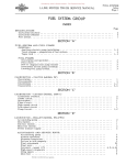
REAR AXLE APPLICATION AND LUBRICATION CAPACITIES
(R- LINE TRUCKS) ~
'"
~
"";
II
CODE
~
::"!l
~
~
-
MANUFACTURER'S IH MODEL NUMBER
ENGINEERING NUMBER HYD.
1401
R-I060
1402
R-1070
AIR
LUB.
CAPACITY
(PINTS)
DESCRIPTION
TRUCK MODELS
IH
Single Reduction
R-II0
IH
Single Reduction
R-120, RM-120, RA-120
4
IH
Single Reduction
RA-140, R-150, 153, RM-150
5
HYD.
AIR 4
----
--_.
1403
R-1170
Single Reduction
R-160, 163, 165, RC-160
IH
Single Reduction
R-164, 170, 173, 175
Single Reduction
R-174 Hydraulic, R-lS0,
R-lS3, lS5, lS53, RC-lS0
11
Single Reduction
R-194, 200, 201, 202, 205
36
R-2464
E-13600
Eaton Two Speed
R-160, 163, 165, RC-160"
13
1411
R-2467
E-13600
Eaton Two Speed
R-164, 170, 173, 175
1412
R-25S5
R-25S6
E-16600
E-16600
Eaton Two Speed
R-174, Hydraulic, R-lS0,
R-18.3, lS5, lS53, RC-lS0
16
1415
R-1540
R-154l
E-2613
E-2614
Eaton Double Reduction
R-lS4, 190, 193, 195
19
1416
R-1640
R-164l
E-2695
E-2696
Eaton Double Reduction
R-194, 200, 205
19
l41S
R-27S0
R-27S1
E-20500
E-20501
Eaton Two Speed
R-190, 200
20
1420
R-1S10
R-lSll
T-U-200P
T-U -200P Timken Double Reduction
R-210
3S
1423
R-2800
R-2S01
T-U -300P
T-U -300P
R-210
37
R-1440
1405
R-1470
1406
R-1530
R-1531
IH
1409.
R-1740
R-1741
T-R-I00
1410
T-R-I00
Timken Two Speed
2t
[Tl
IH
1404
~
S
a
13 ,
S:'
'0
~.
"
~
c:
()
?\
tn
~
@
CIl»
~><
~.
t'
~tz:1
~n
u III
I
~
: ::! tz:1
(1)g»
.... rn~
Donated by John & Susan Hansen - For Personal Use Only
'tI uql"
REAR AXLE APPLICATION AND LUBRICATION CAPACITIES - Continued
,
(R- LINE TRUCKS)
CODE
IH MODEL
ENGINEERING NUMBER
HYD.
AIR
MANUFACTURER'S
NUMBER
HYD,
DESCRIPTION
TRUCK MODELS
AIR
LUB.
CAPACITY
(PINTS)
R-2470
IH Two Speed With
Tim.ken E300 Differential
1426
R-2475
IH Two Speed With
Tim.ken E300 Differential
R-164. 170, 173, 175
1428
RF-1475
E-22M
IH Single Reduction
RF-170
11 ea, axle
1429
RF-1575
E-22M
Eaton Single Reduction
RF-174, 190
14 ea. axle
RF-194, 210
20 Forward
21 Rear
1430
RF-1685
E-36M
Eaton Single Reduction
1433
R-1l65
IH
IH Single Reduction
1435
R-2610
R-2611
TQ-301N
TQ-301P
1436
R-1547
R-1548
TL-101
TL-101
1438
R-2995
R-2996
TL-301
1450
R-2795
R-2796
TR-300
RF-1690
R-160, 163, 165
R-130
6
R-194, 200, 205
32
Tim.ken Single Reduction
R-190, 193, 195
23
TL-301
Tim.ken Two Speed
R-184, 190, 195
29
TR-300
Tim.ken Two Speed
R-200
34
E-36M
Eaton Single Reduction
RF-194,2l0
20 Forward
21 Rear
Tim.ken Two Speed
IH
IH Single Reduction
R-164, 170, 173, 175
8
1453
R-2466
E-13600
Ea ton Two Speed
R-164, 170, 173, 175
11
E-28M
Eaton Single Reduction
RF-174, 190
14 ea. axle
1455
R-2575
R-2576
E-17500
E-1750l
Eaton Two Speed
R-184, 190, 193, 195
17
1456
R-2620
R-2621
E-18500
E-1850l
Eaton Two Speed
R-194, 200, 205
16
1457
R-2366
Eaton Two Speed
R-150, 153
13
1458
R-1572
R-1573
E-1790
E-1791
Eaton Single Reduction
R-184, 190, 193, 195
22
1459
R-1632
R-1633
E-1890
E-1891
Eaton Single Reduction
R-194, 200, 205
21
E-1350
g>
UI~
8
R-1470
RF-1570
L
..'tzJ
o I
e:.~
"'tzJ
8
1452
1454
><
0
N::::OO
1425
1451
PI 'tl
~
()Q~ .....
~
Z
trl
3:
~
~
;;3
cn
~
Ul
~
~
Ell
Donated by John & Susan Hansen - For Personal Use Only
L-UNE MOTOR TRUCK SERVICE MANUAL
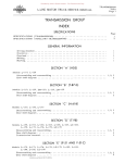
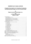
AXLE-REAR Index Page 1 REAR AXLE GROUP
SPECIFICATlONS
Page 1
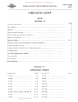
Axle identification chart Specifications • . . . . . Wrench torque chart • . . 2-5 6
SECTION "A"
GENERAL INSTRUCTIONS FOR ALL HYPOID AXLES: Axle housing breather . • . • . • . . . . . • . • . . Axle shaft removal. . . . . • . • . • . . • .
• .•..... Cone center specifications. . • . • . . . •
. •.•. Differential assembly (L-llO, L-l20). • . ,
.•.•.•. Gear adjus tmen t for lash.
. . . . •• Gear tooth contact
.•.•.... Hypoid rear axles. . • . • .
• .•.•.• Lubrication . . . . . . . . . , . . . • . • . Pinion bearing adjustment . . . . . . . . • . . Pinion setting . . . .. . . . . • . • . . • • . . . . Ring gear rivets . • . . . • . . . • • . . . . • . . Single reduction axles - - sec tional views . Straddle mounted pinion bearing . . • . . . • 9
8, 9 I, 2 10 5, 6 1
1
9, 10 6, 7 2, 3, 4 7, 8 11, 12 7
SECTION liB"
TWO-SPEED AXLE -- EATON Des cription. . . . . . • . . . • . Lubrication. . • . • . . . . • . Sectional view • . • . . . • • . Servicing and disassembly. . . . • . 2
3
1
2, 3 SECTION "C"
DOUBLE-REDUCTION AXLE -- EATON
Description . . . . . . . . . . . . , . . . . . • .
Differential lubricators. . . . . • . . • .
Herringbone gear adjus trnent . . . . . .
Herringbone gear shaft (cross-shaft).
Hypoid pinion shaft and adjustment
Sec tional view. . . . • . • . • . • . . . .
2
3
2
2
2
1
SECTION "D"
SINGLE-REDUCTION AXLE -- TIMKEN
Description . . • . . . . . • • . . . . . . • .
Differential carrier bearing pre-load.
Differential disassembly.
Gear adjus tmen t. . . • . • . • .
Lubrication • . . . • . . . .
Pinion bearing pre-load. . • .
Sec tional view . . • . • . • .
Thrus t block ins tallation . . .
Z
4
2, 3 4
5
3"
I
5
SECTION "E"
DOUBLE-REDUCTION, TWO-SPEED -- TIMKEN
Description . . . . • . . . . .
Differential adjus trnent .
Electric two-speed shift
Hypoid pinion and cage •.
Lubrication . . . . . . . . .
Shift collar adjus tment .
PRINTED iN UNITED STATES OF AMeRle ...
1
4
3
2, 3 4
3
Donated by John & Susan Hansen - For Personal Use Only
AXLE-REAR
Index
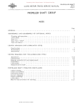
Page 2 L-LINE MOTOR TRUCK SERVICE MANUAL
SECTION "Fit
Page
DOUBLE-REDUCTION -- TIMKEN
Description • . . . • . • • • • • . • . • ,
Helical gear shaft (cross shaft), •.
Hypoid pinion and cage • . • . •
Lubrication. ,
Oil seals • . • . • . , , , . • . • .
I
3
3
3
2
SECTION "G"
TANDEM AXLES
Center cross bar and equalizing beam mounting.
Description . . . . . . . . . . . . . . . . . . . . . . . . . . . . . . . . . . . . . . . . . . . . Di'£ferential lock. • . • . • . • . • • • • • . • . . . • • • , Disassembly of power divider (axle mounted) .•. Equalizing beam ends. , , . • • . . . • • . . . • • • • . Legends for sectional view. . • . • . • . . . . . . • • Sectional view (axle mounted power divider) . , • Torque rod ends . . . . . . . . . . . . . . . . • . . . . . . . . . . . 4
I
2
3,4
4. 5 2
I
5
SECTION "H"
ELECTRIC SHIFT
Axle shift unit • . • . • . , .•• , ••.
Axle unit disassembly . . . • . • • • .
Des cription • . . . • . : .••
Lubrication • . . . • . • . • • • .
Par ts identification lis t. . • . . . . .
Service and trouble-shooting ..
Shifting ins tructions • .
Speedometer adapter ..
Wiring system . . • . • .
2, 3 4-7 1, 2 4
8
3,4 7
2
2
Donated by John & Susan Hansen - For Personal Use Only
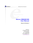
REAR AXLE IDENTIFICATION CHART 0
Axle Axle
Code Model
Nwnber Nwnber 0
0
,
0
,
0
'
1401 __ R-1060 Single-ReduCtion-IH•
..• ~ ...
- '
1402 R-I070 Single - Reduction-IH. • . •
XX .. :-
1403 R-1l70 ~!!!gle-Recluction-IHo •.•
X X X X
1404__ .&-}440 ~ Sinde-Reduction-IH••••
X X
XX
R-1470 SinKle-Reduction-IH••
1405
X
X X
X
R-1530 Single-Reduction-IH•• 1406
X
1407
R-1555 Sin~-.Reductio~n .
1408
R-1630 Single -Reduc Hon -Ea ton •
~.09 R-1741 Sing!E):~educ tion- Tirnken
R-2465 Tw<?~~.ed-:~a.~on_._._~~.~~~.
1410
XX
XX 1411
R-2466 Two-Speed-Eaton • X
X
X X
l- 1412
R-2585 Two-S:eeed-Eaton •.• ~.
X
R-2580 ~~p!:~.<i-E~ton •.•••
1413
1414 R-2000- Two-Speed-Eaton •••••
!---
1415 R-1540 Doub1e-Reduction-Eaton.
-R:'-1640
1416
DoulJ1e-Recl_~_H<:>n-Eat0!1...!. f - - !---- --,f'" 1417 1418 R-1731 Douh1e-Reduction1419
Tirnken • • • • • . . • . •
R-1810 Doub1e-Reduction1420
Tirnken
,J1~L~_ R~1140 ~l1gle-Reduction,::.Tirnken
1422
R-2741 Two-Speed-Tirnken ••••
l-
R'::Z800
1423
~Speed- Tirnken ••.•
1424----1425 R-2470 Two-Speed with Tirnken
~:---!'--~~
0
::
0
,
-
0
0
r
~~~
0
•
0
•
-~-
0
tz
~~
~.
X X
•••
$
X X
X
~
X
l -I -
X X
-;
XX
X
XX
:;0
XX
X
------
X
X
X
X
0
•
0
•
0
•••
0
f- 1-"
.~~
i-- !---
A
UJ
~~-
----
[TJ
:;0
<
~~
.
~~.
X
l
X
X
n
I~~~-
[TJ
XX
•
-~
o
f-- I-
XX
X
C
X
~~~-
o
:;0
l - I---
I~~-
I-~
XX
X
~~
----
[TJ
- I--
X X
X
-
0
--~
.
0
0
~ 0' O~ tOO
o~ 0 ~ 0 M to
...... 0 M ~ U') >.00 M~
M~ U') COo M
o U') No M
...... N , M ...... to U') ,>.0 >.0 >.0 >.0 ..... r- r-r- ~ """0
0' ~~ ..... ...... 0 0 ON ~ N NN NM N
co ...... 0'
...... ..... ...... ..... ..... co coco
......
......
...... ......
...... ...... ......
......
I NN N '
............
......
NN IN I ...... , I 1
,
I -;'~
I I!l 1
1 ~-;' 1 I 1 UI I
I Pt!1
UI I .....I I U
I
1
IU ~ ~ I I Pt!1 Pt!
...:I ...:1...:1 ...:I ...:I ...:I ...:I ...:1...:1 ...:I ...:I ...:I ...:1...:1 ...:1...:1 ...:I ...:1...:1 ...:1...:1 ...:l ...:1...:1 ...:I ...:I ...: ...:I Pt!
...:I ...:1...:1 ...:1...:1 ...:I .... ...:1...:1 ...:1...:1 ...:I
DESCRIPTION
t- I-
$
»
z
c
»
r
X
t-~
X
-------------
Di.f.f.
10 * .............. R-2-'!'75 Two':"Speed with Tirnken
i=-~ Difh...!_L~.· • . • • 1427 ~ R:'::Z590- Two-Speed with Tirnken 0
Dirf. '0
••
0
~~~
t
~~-
~
l-I-
i-
----
,0
I - I",
~>
•••••••
RF-1475 Single -Reduc tion::IH. _____.•
-1428
--RF'::Ts75 ~~!!g!e::~~dt1c~~on-IH••••
1429
RF-1685 ~_~!!gle-Reduction-~_~ton.
1430
1431 --
1432 1433
R·1l65 Single-Reduction-IH.• :-:.
X
X
I'"
,-
~~
-~
X
I-~
!--- I-
I- -
P. ~ - ---~
i-- i--
C' '--
X
I~~~
- - I
'---
\:!!tzl
ItJ (") I
III III ):tJ
OQ po: 1.'1
~
g >
-
UI
):tJ
Donated by John & Susan Hansen - For Personal Use Only
REAR AXLE SPECIFICATIONS
'tJUl)
------
- . - . - ................
~-
:root:"'
~ ><
--
~--
~M
N ....
RF-1475
REAR AXLE MODEL
R-I060
R-I070
R-1165
Code . • . . . . . . . • . • . . . • . .
1401
1402
1433
Type (Semi or Full-Floating).•
Semi
Full
Pinion Mounting . . • • . • • . .•
Straddled
Straddled
R-1440 R-1470 1403 1404 Full
Full
Straddled
Straddled
R-1l70
o
Forward
RF-1476
Rear
RF-1477
1405 1428
1428
Full Full Full
Full
Str-addled Straddled Overhung
Straddled
---
Number of splines . • • . • • •
Pinion Cone Center (amount of
variation marked on pinion).
p:M
0)
~:;l:I
r
tz
[Tl
Axle Shaft:
Diameter at splines • • . . . •
I
p.>:;l:I
1-9/32"
10
1-9/32 11
1-33/64"
16
10
1-33/64"
1-3/411
1-3/4"
16
16
16
1-3/411
16
1-3/411
16
~
o
d
:;0
--l
2.609
2.609
2.984
2.984
3.253
3.253
4.156
3.253
:;0
C
(')
Lubricant Capacity (Pints) •.•
Axle Ratios • . • . . . • . • . • . •
4
3.73
4.1
4
4
8
3
8
8-Axle
3-P.D.
8
(J)
[Tl
:;0
4.1
4.777
5.13
4.88
5.571
6.166
4.88
5.57
6.16
5.285
6.166
6.666
7.166
6.166
6.666
7.166
6.166
7.166
6.166
7.166
10
10
10
10
10
10
10
10
Cage Rotating Torque Scale
Reading (Lbs.) • . . . • . . . •
10-25
10-25
10-25
10-25
10-25
10-25
10-25
10-25
Pinion Nut Torque (Ft. Lbs.) .•
200-230
200-230
200-230
200-230
200-230
280-300
350-400
280-300
•005"-. 007" .005" -.007 11 .005"-.007 11 •005" -. 007" .005" -.007 11 .005" -.007" .005 11-.007 11
---
* Pressure against bearing race when checking rotating
---
--~
---
torque of pinion cage.
~
-.---
............
<
(')
[Tl
~
Pinion Adjus trnent:
Press pressure (tons)* . . . •
Differential Bearing Pre-load.
(Total). • . • • . • • • . . . . . • .005 11 -.007"
A
...........- -
»z
c
»
r
Donated by John & Susan Hansen - For Personal Use Only
REAR AXLE SPECIFICATIONS RF-1575
REAR AXLE MODEL
R-1530
R-1540
RF-1685
R-1555
Code . • . • • • • • . • . . • • . . . •
1406
1415
1407
1429
1429
Forward
RF-1686
1430
Type (Semi or Full-Floating).•
Full
Full
Full
Full
Full
Full
Forward
RF-1576
Rear
RF-1577
Rear RF-1687 R-1630 -----
1430 1408 Full Full ~
r
Pinion Mounting . • • • • • • . . •
Straddled
Overhung
Straddled
Overhung
Straddled
Overhung
Overhung Straddled $:
Axle Shaft:
Diameter at splines • • . . . •
Number of splines • . • . . . .
Z
[l1
1-7/8f!
16
1-63/6411
1-63/6411
16
16
1-3/411
16
1-3/41!
16
2-1/8 11
16
2-1/8
16
2-1/8"
16
o
-1
o:;0
-1
:;0
Pinion Cone Center (amount of
variation marked on pinion).
C
3.472
2.500
3.844
4.656
3.473
4.875
4.875
2.937
()
A
fJ)
Lubricant Capacity (Pints) • . .
Axle Ratios • • • • • • • • • . • . .
Pinion Adjus trnent:
Press pressure (tons)* • • . .
II
20
19
12-Axle
3-P.D.
5.571
6.5
7.166
7.049
7.754
9.025
5.571
6.5
7.166
6.166
7.166
10
10
10
10
--------
12
6.166
7.166
10
20-Axle
3-P.D.
5,756
6.940
10
-----
21
18
<
5.756
6.940
10
5.571
6.5
7.166
10
----------
Cage Rotating Torque Scale
Reading (Lbs.) • • • . • . . . •
10-25
10-25
10-25
10-25
10-25
10-25
10-25
10-25
Pinion Nut Torque • • • • • . • . •
280-300
280-300
350-400
350-400
280-300
600-900
400-500
350-400
Differential Bearing Pre-load.
(Total) • . • • • • • . • . • . . . • .005" -. 007" .005" -.007" .005" -.007" .005"-.007" . 005" -.007" •005" -. 007" .005" -.007" •005" -,007"
*
[l1
:;0
n
[l1
$:
»z c
»
r
en
'U'tl
>
:~~
(l)!::;t"
I.»~·M
III I
p:~
Pressure against bearing race when checking rotating torque of pinion cage,
oM
::s>
(f)~
Donated by John & Susan Hansen - For Personal Use Only
"tI
REAR AXLE SPECIFICATIONS
--
REAR AXLE MODEL
Code • • . . . • • . . • . . . • • . . •
R-1640
1416 R-1730
•
•
•
..
D
..
..
---
t"'
~S!M
n I
1lll:t1
R-1740
R-1810
R-2465
R-2466
R-2470
1419
1421
1420
1410
1411
1425
g.~
~ l:t1
-
Type (Semi or Full-Floating) . .
Full
Full
Full
Full
Full
Full
Full
Full
Pinion Mounting • • . • . • . • . •
Overhung
Overhung
Overhung
Straddled
Overhung
Overhung
Overhung
Overhung
r
r.
Axle Shaft:
Diameter at splines . • . • . •
Number of splines • . . . • . •
2-1/8 11
2-3/8 11
16
2-3/8 11
16
16
2-3/8 11
16
2-3/8 11
16
1-3/4"
16
z[TJ
1-3/411
1-3/4"
16
$:
o
16
-l
Pinion Cone Centers (amount of
variation marked on pinion).
2.625
Lubricant Capacity (Pints) •.•
19
.
.
.
. .
.. .. ..
38
. .. ..
o
. . ..
.. .. .. .. .. .. .. .. .. . . . .. . .. .. .. .
38
36
38
4.281
4.281
13
13
. .. .. . . . . ..
.. . .
. .. .. .
:;;0
;j
C
()
Axle Ratios • . • . • • • • • • . • •
7.049
7.754
9.436
5.91
6.51
7.79
8.69
9.76 5.91
6.51
7.79
8.69 9.76
5.28
6.83
7.41
5.91
6.51
7.21
7.79
9.76
5.14-7.15
5.83-8.11
6.33-8.81
5.l4-7.l5
5.83-8.11
6.33-8.81
6.13-8.10
6.70-8.86
A
tn
~
<
()
[TJ
Pinion Adjus tment:
Press pressure (tons)* .•••
10
10
10
10
10
10
10
.. . .. ..
,.
Cage Rotating Torque Scale
Reading (Lbs.) • . • • . . . • •
10-25
4-5 &:
4-5 &:
4-5, &:
4-5 &:
10-25
10-25
. .. . .
. .
Pinion Nut Torque (Ft. Lbs.) ••
400-500
700-900
700-900
700-900
700-900
280-300
280-300
See Note
See Note
See Note
See Note
-
. .. . . ..
&: Tirnken Axle. Tighten one notch each from .000" end play. torque of pinion cage. ..
. ..
.. .
•005" -.007" • 005" -. 007" .. .. .. .. .. . , ..
---
* Pressure against bearing race when checking rotating
NOTE:
.. . .
$:
»z
c
Differential Bearing Pre-load.
(Total)• • • . . . . . . . • • . . . .005"-.007"
>
~ n
--
R-1731
..
CIl
Jg ~ ~
--
»r
Donated by John & Susan Hansen - For Personal Use Only
REAR AXLE SPECIFICATIONS REAR AXLE MODEL
R-2475
R-2580
R-2585
R-2740
R-2600
R-2590
R-2741
R-2800
-----
1426
Code ................... ................
1413
1412
1427
1414
..
. .. .. . . .
.
1422
1423 -----
---
Type (Semi or Full-Floating).•
Full
Pinion Mounting . . • • . • . . . . Overhung
Full
Full
Full
Full
Full
Full
Full
Overhung
Overhung
Overhung
Overhung
Overhung
Overhung
Overhung
~
C
---
Axle Shaft:
z
I
1-3/411
Diameter at splines . . • • . .
1-63/6411
16
Number of splines • . • • • . •
1-7/8 11
1-7/8 11
16
16
2-3/8 11
2-1/8 11
16
[l1
16
2-3/8 11
16
3:
2-3/8 11
16
o
--l
o
;0
16
-----
Pinion Cone Centers (amount of variation marked on pinion). . .
Lubricant Capacity (Pints) •••
"
. . .. .. ..
5.281
. .. .. . .. ..
4.B12
22
20
.. .
.. .. .. .. ..
.
. .. .. .. .. .. . ..
5.281
.
.. .. ..
. .. ................
37
22
---Axle Ratios • . • . • . . . • • • . • 6.13-B.I0
6.70-8.86
.. ..
37
.
--l
..
;0
. .. .. . .. . C
() ~ 37
fJ) ---
5.571-7.594 5.571-7.749
6.5-B.B66 6.166-8.577
6.5-9.041
5,95-7.30
5.571-7,594
6.13-B.15 6.500-8.866
6.66-8.85 4.93-5,91
6.42-8,38
6.99-8,38
4.93-5.<:1
6.42-8.38
6.99-8.38
[l1
4.93-5.91
6.42-8.38
6.99-8.38
;0
<
n
[l1
-----
Pinion Adjus trnen t:
Press pressure (tons)* . • . .
. .. .. . .. .. .
Cage Rotating Torque Scale
Reading (Lbs.) • . • . • . . . • . .. .. ..
. .. .. .
-Pinion Nut Torque (Ft. Lbs.) .•
. .. .. .. .. .. .. .
10
10
.. .. . . .. .. .. ..
10
25
25
25
10-25
10-25
. . .. .. .. . .. ..
10-25
4-5 &:
4-5 &:
4-5 &:
BOO-IIOO
800-1100
800-1100
See Note
See Note
See Note
----
~--
350-400
280-300
---
.. .. .. .
.. ..
.. ..
---
Differential Bearing Pre-load.
(Total)• . • • . . . • • . • . • . • . . ..
.
..
3:
»
z
c
»
r
350-400
----
. .. .. .005" -.007" .005"-,007" .. . . .. .. .. .. .. .005" -.007"
.g>>
t1I :><
8.1:"'
!:t!M
* Pressure
agains t bearing race when checking rotating torque of pinion cage. &: Tirnken Axle.
NOTE: Tighten one notch each .from .000" end play.
'U (")
I
Pl~~
OQ
(I)
.....
M
g >
\J1Ul~
Donated by John & Susan Hansen - For Personal Use Only
AXLE-REAR
Specifica tions
Page 6
L-LlNE MOTOR TRUCK SERVICE MANUAL
B
Socket
Handle
A-22879
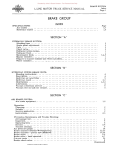
FT. LBS. WRENCH EFFORT ON WRENCH (APPROX.) TORQUE
A
B
200
1 foot
2 feet
200 Ibs. 1001bs. 250
1-1/2 feet
2 feet
170 Ibs. 125 Ibs. 300
1-I/Z feet
Z feet
3 feet
200 Ibs.
150 1bs.
100 1bs.
350
2 feet
2-1/2 feet
3 feet
3-1/2 feet
175
140
118
100
1bs.
Ibs.
1bs.
1bs.
450
2-1/2 feet
3 feet
3-1/2 feet
4 feet
180
150
129
113
Ibs.
1bs.
1bs.
1bs.
500
3 feet
3-1/2 feet
4 feet
4-1/2 feet
167 Ibs.
1441bs.
1Z5 lbs.
112 1bs.
550
3-1/2 feet
4 feet
4-1/2 feet
5 fee t
158 1bs.
1371bs.
123 1bs.
110 Ibs.
600
4 feet
4-1/2 feet
5 feet
15-1/2 feet I
1501bs.
1341bs.
1Z0 Ibs.
110 1bs.
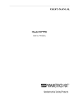
Wrench Torque Chart
The above chart illustrates the length of
the wrench handle (A) and the effort that must
be applied at (B) when tightening to secure the
indicated torque.
Donated by John & Susan Hansen - For Personal Use Only
AXLE-REAR
Section A
Page I
L-L1NE MOTOR TRUCK SERVICE MANUAL
AXLES-REAR GENERAL INSTRUCTIONS FOR ALL HYPOID AXLES HYPOID REAR AXLES (ALL MODELS)
REAR AXLE HYPOID GEAR REPLACEMENT
AND ADJUSTMENT
All rear axles have a hypoid :ring gear and
pinion, whether single reduction, double-Teduc
tion, double-reduction (single and two-speed
final drive) and two-speed differential. Hypoid
gears have a greater inherent torque capacity,
due largely to the fact that the hypoid pinion is
much larger in diameter and the pinion teeth
are correspondingly larger than those found in
a spiral bevel pinion for the same number of
teeth and the same diameter ring gear.
The hypoid pinion has a longer face because
of its offset location. It also has larger tooth
surface areas and usually has more teeth in
ins tant contact with the gear, It is thes e design
characteristics which contribute to greater
strength and quieter final drive operation. Be
cause of this greater tooth contact, it is more
difficult to secure correct pinion setting at
time of overhaul or when replacing differential
bearings and every effort must be made to be
sure the final setting results in best possible
tooth contact,
Hypoid Gear Tooth Contact (All Models)
The proper adjustment of hypoid gears in
assembly is a vital factor in obtaining quiet and
durable gears and the same methods of adjust
ment applies to both straight, spiral bevel and
to hypoid type gears.
There are two distinct considerations in
obtaining the proper tooth contact, cone center
and backlash.
Hypoid as well as bevel and spur gears are
cut with a predetermined amount of backlash.
The backlash usually varies from .004" to
.005" on small gears and increases on large
gears. Generally, the gears are machined to
run flush with each other at the outer end (heel
or large end) of the tooth, and gears should be
set according to their theoretical cone center
(Figs. 2, 3, and 4).
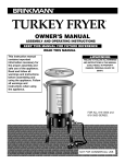
Cone Center Specifications
Note that the pmlOn center line (E, F) is
offset from the ring gear center line (C, D).
Matched and mated hypoid ring gears and
hypoid pinion gears are furnished both for
service and for production.
Mated gears are marked with figures
showing the amount of variation from their
theoretical cone center.
~~-----------D
,F
Tbeoretical cone center of
_ ' , / bevel drive gear and pinion
~~~Ii!--Ilt-~ ~ ..
~.,,,
.
I
i
pinion
A-22797
Fig. 2
A-2282B
Fig. I - Illustration shows location of pinion
in relation to center 1ine of ring gear. Center
line of pinion is below center line of ring
gear.
NOTE: When adding to or replacing lu
bricant in a rear axle having hypoid gears, use
only hypoid lubricants. (See under "Lubrica
tion" on page 9)
PRINTED IN UNITED STATES OF' """EAtCA
Fig. 2 illustrates a hypoid ring gear and
pinion adjusted to theoretical cone center,
wherein the cone centers of both gears coincide.
The specifications in this case would be the
distance from the line (A, B) (Fig. 1) drawn
through the center of the hypoid ring gear to
the ground face of the hypoid pinion on center
line (E, F). On some axles, the pinion is lo
cated above the center line (C, D) (Fig. 1). In
these cases the term "hypoid" still applies.
Donated by John & Susan Hansen - For Personal Use Only
AXLE-REAR
Section A
Page 2
L-UNE MOTOR TRUCK SERVICE MANUAL
center of pinion
Bracket screw
Fig. 3
Fig. 3 illustrates a setting wherein the
mating of the gears has necessitated the pinion
cone center being farther than the ring gear
center. The pinion marking in this case will
be minus (-) because the distance from the ring
gear center is less.
01 b"d
~:M;\. eo..~_""'"
.
......-.:
~~- ..
..
i
- ;;a
driv. gw
A-22BOI
Fig.
A-22494
..
~
Fig. 4 illustrates a condition where the
mating of the gears required the pinion cone
center to be farther OUT. The pinion marking
will be plus (+) because the distance is greater.
SE-1065 Pinion Setting Gauge
The SE-I065 pinion setting gauge is a pre
cision gauge designed for use in adjusting
differentials to the proper cone setting of the
ring gear and pinion. It is used only in adjust
ment of matched sets of gears. A step plate
and bracket have been added to the set so that
the gauge may be used on all hypoid differen
tials with satisfactory results.
NOTE: Be
sure to allow for thickness of the step plate
.400" when making calculations (Fig. 5).
The use of SE-I065 gauge makes possible
the exact duplication of the setting etched on
the pinion. This results in the best possible
setting with a minimum loss of time. It is ad
visable to check all pinion settings with a paint
impression before considering the work com
plete. By so doing, visible proof of the pinion
gauge setting accuracy is obtained, also long
and quiet gear performance is assured.
F j g. 5
Fig. 5 shows SE-I065 tool equipment in
position on hypoid differential case. Make
certain that the bearing bores are clean and
free of nicks or burns. The step plate must
be placed on the pinion end so that the lugs in
the step plate straddlt; the bearing staking in
dentations on the smaller axles.
2. Install step plate and bracket as shown in
Fig. 5. CAUTION: Be sure lugs on step
plate straddle the bearing staking indenta
tions.
3. Mount assembled SE-I065 gauge in bearing
bores of carrier.
4. Take micrometer reading to check point of
pinion. Add .400 11 (thickness of step plate)
to reading. Write down reading.
5. Locate specified cone center specification
for particular model on chart. Write down
specified figures.
6. Locate on pinion the etched marking which
indicates variation from zero cone center.
If a minus figure, subtract from specified
cone center, and if a plus figure, add to
specified cone center. Results of calcula
tion give corrected cone center.
7. Comparison of corrected cone center (6)
with actual measurement (4) indicates
amount of change necessary for pinion
position.
Adjustment of differentials is a simple
matter with the SE-I065 gauge. Briefly, it is
only necessary to:
8. Install ring gear and carrier in position.
1. Install pinion and bearing assembly
differential carrier.
9. Adjust backlash according to marking on
ring g ear. (See following page) in
Donated by John & Susan Hansen - For Personal Use Only
L-UNE MOTOR TRUCK SERVICE MANUAL
Example of Mathematics involved;
Truck model to be L-llO.
(a)
(b)
Micrometer reading (add
.400" for step plate) . .•
.. 3.4400"
Specified cone center on
chart • . . . . . . . . .
Checking tooth contact is accomplished by
means of oiled red lead applied lightly to the
bevel gear teeth (Fig. 6). When the pinion is
rotated, the red lead is squeezed away by the
contact, of the teeth, leaving bare areas the
exact size, shape, and location of the contacts,
3,400 11
(c)
Pinion marked (-5) . . .
.005"
(d)
Subtraction (b-c) gives
corrected cone center.
3.395"
(e) Subtract corrected cone
center (d) from actual
measurement (a) . . • . .
AXLE-REAR
Section A
Page 3
.045"
(f) It is necessary to move
pinion IN. . • . . . . . . . .
(g) Remember -- It is essential to arrive
at a measurement as nearly equal the
corrected cone center as possible.
Fig. 6
(h) DO NOT FAIL TO VERIFY ACCURA
CY OF THE ADJUSTMENT SECURED
WITH THE SE-l065 gauge by checking
the gear tooth contact using the paint
impression method as set forth under
General Rear Axle Hypoid Pinion and
Ring Gear Adjustment, which follows.
GENERAL REAR AXLE HYPOID PINION
AND RING GEAR ADJUSTMENTS
Fig. 7
(PAINT IMPRESSION METHOD)
The following general instructions and
suggestions are for the benefit of those service
stations not equipped with an SE-l065 pinion
setting gauge. Bear in mind that the accuracy
of the adjustment obtained with the following
procedure is dependent upon the skill of the
operator.
Hypoid gears when mounted should show a
bearing toward the toe or small end of the
tooth, never atthe heel or large end, the reason
being that it is practically impossible to make
gears and gear mounting rigid enough so that
there will not be some slight deflection when
fullloadis applied. This always has a tendency
to caus e the bearing to come on the heel of the
tooth and when gears are adjusted so that the
bearing is toward the heel of the tooth it re
s ults in a concentration of load on the top cor
ner of the heel and breakage will follow.
PRINTED IN UNITED STATES OF AMERICA
Sharper impressions may be obtained by
applying a small amount of resistance to the
gear with a flat steel bar and using a wrench to
rotate the pinion. When making adjustments,
check the drive side of the bevel gear teeth.
Coast side contact should be automatically
corrected when drive side contact is correct.
As a rule, coating about twelve teeth is suffi
cient for checking purposes.
With adjustments properly made, the
correct tooth contact shown in Fig. 7 will be
secured. The area of contact starts near the
toe of the ,gear and extends about 80 per· cent of
the tooth length. This adjustment results in a
quiet running gear and pinion set which, because
the load is distributed over the te eth within the
proper area, will deliver all the long service
built into it.
Figs. 8 to 11 illustrate method of adjust
ment in securing the proper gear tooth contact.
Donated by John & Susan Hansen - For Personal Use Only
AXLE-REAR
Section A
Page 4
L-UNE MOTOR TRUCK SERVICE MANUAL
A
A
CONTACT
4,OJUSTMENT
Conlac1
adjustm€nt
B
B
BACK lASH CORRECTION Sack lash
c.orrection
A HIGH NARROW CONTACT IS NOT
DESIRABLE. If gears are allowed to operate
with an adjustment of this kind, noise, galling
and rolling over of the top edges of the teeth
will result. To obtain correct contact, move
pinion toward bevel gear to lower contact
area to proper location. This adjustment will
decrease backlash between pinion and bevel
gear teeth, which may be corrected by moving
bevel gear away from pinion. Backlash of
..006" to .012" is correct.
A SHORT TOE CONTACT IS NOT DE
SIRABLE. If gears are allowed to operate
with an adiustment of this kind, chipping
at tooth edges and excessive wear due to
small contact area will result. To obtain
correct contact, move bevel gear away
from pinion. This will increase the length
wise contad and move contact toward heel
of tooth. Correct backlash of .006" to .012"
can be obtained by moving pinion toward
bevel gear.
A·15847
Fig. 8
A-15849
Fig. 10
A
A
CONTACT
CONTACT
ADJUSTMENT
AOJUSTMf:NT
B
B
BACK LASH
CORRECTION
A LOW NARROW CONTACT IS
BACK LASH
CORRECTION
NOT
A. SHORT HEEL CONTACT IS NOT DE
SIRABLE. If gears are allowed to operate
with an adiustment of this kind, chipping,
excessive wear and noise will result .• To
obtain correct contact, move bevel gear
toward pinion to increase the lengthwjse
contact and move contact toward toe. Cor
rect backlash of .006" to .012" can be ob
tained by moving pinion away from bevel
gear.
Several adiustments of both pinion and gear
may be necessary before correct confact
and backlash are secured.
DESIRABLE. If gears are allowed to oper
ate with an adiustment of this kind, galling,
noise a nd grooving of teeth will result. To
obtain correct contact, move pinion away
from bevel gear to raise contact area to
proper location. Correct backlash of .006"
to .0l2/f may be obtained by moving
bevel gear toward pinion.
A-15848
A·JSBSO
Fig. 9
Fig. I I
Donated by John & Susan Hansen - For Personal Use Only
L-L1NE MOTOR TRUCK SERVICE MANUAL
AXLE-REAR
Section A
Page 5
Gear Adjustment for Lash
Generally if original gears are being rein
stalled, red leading of teeth will not indicate
the same contact as new gears and can be mis
leading. Gears that have been in service for
long periods form running contacts due to wear
of teeth; therefore, the original shim pack
should be maintained to check gear lash. Gear
lash, when using original gears, can be reduced
only to a point of smooth rotation of gears.
If the gear lash is in excess of maximum
tolerance as stated under Gear Adjustment, the
lash may be reduced only in the amount that
will avoid overlap of the worn tooth section
(Fig. 12).
Rotate the gears and check for
smooth or rough operation. If a slight overlap,
as illustrated (Fig. 12),takes place at the worn
tooth section, rotation will be rough.
Fig. 13 - Checking gear lash.
Worm section
of ring gear
Pinion too deep in ring gear Adjust Differential Bearing Pre-Load
Using dial indicators at side of each bear
ing cap (Fig. 14), adjust to obtain bearing pre
load as follows:
Ring gear
Correct Overlap
1. Loosen adjusting nuts only enough to notice
end play on indicators.
2. Tighten adjusting nuts only enough to obtain
.000" end play reading on indica tors.
Note: While gear is held in ,000" end play
and before loading bearings. check gear
for runout. If runout exceeds .008". re
move differential and check for cause,
Incorrect
Dial indicators
A-19693
Fig. 12
Fig. 12 illustrates worn condition of gear
teeth and overlapping condition.
When installing new gears, check gear
lash with dial indicator (Fig, 13) and adjust to
obtain amount of backlash marked on ring gear
as follows:
1. Set pinion according to procedure outlined
under SE-I065 Pinion Setting Gauge.
2. To move ring gear, tighten or loosen
differential bearing adjusting nuts as re
quired.
3. After correct gear lash is secured, check
and adjus t as neces s ary to obtain the
correct tooth contact. (See Gear Adjust
ment for correct tooth contact.)
PRINTED IN UNITED STATEs OF AMERICA.
Fig. I~ - Adjusting
load.
differential
bearing pre
Donated by John & Susan Hansen - For Personal Use Only
AXLE-REAR
Section A
Page 6
3. L-UNE MOTOR TRUCK SERVICE MANUAL
Tighten BOTH adjusting nuts from .000"
end play to pre-load differential bearings.
Adjust pre-load to secure equal pre-load
reading at indicators. (See specifications
for pre-load data on the various axles.)
4. Tighten bearing cap stud nuts to specified
torque.
5. Install adjusting nut locks.
Pinion Bearing Adjustment for Pre-Load Using
Dial Indicator (This method should only be used
on the smaller axles).
An outside or bench assembly should be
made of bevel pinion, bearings and cage. With
cups assembled in cage, assemble the pinion
and inner bearing cone and roller assembly in
place, using the proper spacer to space the
pinion bearings. Next assemble the outer pin
ion bearing cone and rollers, spacer, compan
ion flange, washer and nut.
Pinion Bearing Adjustment for Correct
Pre-Load (Torque Method)
After the pInIon, the pInIOn bearings and
spacers have been assembled in the pinion
bearing cage, place the assembly in a press
being sure to use a sleeve adapter as shown in
Fig. 15. Press the bearing down firmly and
rotate the pinion cage to align the bearings and
assure normal bearing contact. Set press at
correct pressure and attach a spring scale to
pinion cage as indicated in Fig. 15. Read scale
only while pinion cage is turning. If preload
reading is incorrect, thE7 bearing load may be
increased by installing a thinner spacer ot
decreased by using a thicker spacer.
The correct press ram pressure and scale
reading for the various axles may be found in
the Rear Axle Specifications.
Fig. 16
Fig. 16 shows method of attaching dial
indicator when adjusting bearing pre-load.
This method can be used when press equipment
is not available.
NOTE: Do not install pinion bearing oil
seal until all adjustments have been completed.
Then check bearing fit to see that bearings
have no end movement with flange nut drawn
up tight. To secure this fit, p'roper spacer
must be found by trial as follows:
Fig. 15
Fig. 15 shows method of checking pinion
bearing preload using scales to measure
torque.
(I) Place assembly in vise in position shown.
(2) Mount indicator on propeller shaft flange
with indicator finger resting on upper face
of cage. (See A, Fig. 16.)
(3) With the tips of the fingers grasp the bear
ing retainer and work bearings up against
the back face of pinion. (See B, Fig. l6.)
(4) With the bearings held firmly against the
pinion, move the cage up and down, ob
serving the indicator reading. It is im
possible to accurately determine the end
play unless the bearing is worked loose
and up against the pmIon. Assemblies
having as much as .005" end play cannot
be moved enough to show on the indicator
until the bearing has been worked up and
away from the cup.
CAUTION
Bearings must be absolutely clean!
Donated by John & Susan Hansen - For Personal Use Only
L-UNE MOTOR TRUCK SERVICE MANUAL
AXLE-REAR
Section A
Page 7
Preload the pinon bearings by replacing
the spacer between the pinon bearings with one
smaller to the extent of the amount of the end
play plus .002t! for the loading, For example,
should there be .005" end playas indicated in
the sketch in the assembly, replace the spacer
with one .001" smaller. Do not depend upon the
spacers to be right according to number but
check each and everyone with an accurate
micrometer. Before reassembling the bear
ings to the pinion shaft they should be dipped
in rear axle lubricant. Propeller shaft flange
nut must be pulled down securely to assure
tight bearings. A wrench with 30 11 of leverage
should be used,
In order to determine if insufficient or
excessive preload has been applied, make the
following te st:
A-22727
(1) Place assembly in vise with jaws clamp
ing together on the flange of the pinion
bearing cage and with assembly in a hori
zontal position.
(2) Grasp the propeller shaft flange with one
hand and attempt to turn.
(3) If the pinion turns freely, assembly is too
loose. If pinion cannot be turned', assem
bly is too tight,
(4) The ideal condition is to secure a firm
drag when turning the pinion cage by hand.
Fig. 17 - Using the pinion staking tool.
Pinion Bearing (Straddle bearing)
The straddle pinion bearing is held in
place on the pinion by a staking operation.
The staking operation is accomplished
through the use of a hydraulic or screw press
applying 18 to 20 tons pressure on the special
staking tool as illustrated in Fig, 17, The re
sult will be uniformly spaced ball indentations
that securely lock the pinion bearing to the
shaft.
After proper bearing fit has been obtained,
place pinion bearing cage shims approximately
.020 in thickness over end of cage and place
cage and p,inion assembly in carrier, it being
necessary to match flange holes in cage, since
one hole is out of equal spacing to assure prop
er position of cage. Next assemble two cage
bolts only until gear setting is completed.
Assemble differential and bevel gear assem
bly and place bearing cap and adjuster in posi
tion, Tighten bearing cap bolts and back off
slightly to provide sufficient Iposeness to allow
turning the adjuster for a temporary backlash
adjustment of approximately .01 Ot!, After this
adjustment has been made, tighten each bearing
adjuster snug then give them a final tightening
operation, drawing them up to secure the .005"
to .007" total bearing'pre-load. This is im
portant in order to make certain that the bear
ings are seating properly.
Rivet Pressures
IMPOR TANT: Hypoid drive pmlon oil
seals must be soft and pliable before being in
stalled if the seals have become dried out and
hard while in stock, use kerosene and work it
in thoroughly. When seal has become soft and
pliable, dip it in hot oil and work this oil in
thoroughly.
Proper installation of differential ring
gear rivets demands that sufficient pressure
be applied to the rivets to expand them and
cause them to completely fill the holes in which
they are installed. Riveting should be done
with COLD rivets, Hot rivets will shrink when
cool, leaving s space and inviting shearing upon
the application of torque.
PR!NTED IN UNITED STATES
or
A ME J<:IICA
Differential Ring Gear Rivet Removal
If necessary to remove hypoid ring gear or
herringbone gear rivets, drill the rivet heads
from the gear side, using a drill slightly larger
than the rivet itself. Use a punch for the re
moval of the remaining portion of the rivet.
(See Fig. 18).
Knocking off or "busting" rivets is a dan
gerous practice both from the standpoint of
personal safety and because such practice may
cause distortion to the gear carriers or gears
and will elongate the rivet holes.
Donated by John & Susan Hansen - For Personal Use Only
AXLE-REAR
Section A
Page 8
L-UNE MOTOR TRUCK SERVICE MANUAL
Difierential case
A-22831
Fig. 18 - Drill rivet head and punch-out
as shown.
rivet
Riveting Jig SE-1575 is available and is
designed for use with hydraulic or ITlechanical
press equipITlent.
A.loon
Fig. 19 - Using a heavy hammer, strike sharply
on the center of the flange of the axle shaft.
This wi II unseat and loosen the tapered dowels
in each stud hole.
The following pressures are recoITlITlended
for differential ring gear rivet installation:
RIVET SIZE
(INCH)
PRESSURE
PER RIVET
(TONS)
5/16
3/8
7/16
1/2
9/16
5/8
12
17
30
45
60
60
to
to
to
to
to
to
15
20
35
50
70
70
Axle Shaft Removal (Timken Axles)
Axle shafts are attached to the wheel hubs
by studs and nuts at the flanged ene.. Stud holes
in each axle shaft flange are taper-reaITled to
receive split tapered dowels.
When disasseITlbling the axle, SOITle of the
bearing cage studs or axle shaft studs ITlay turn
loose froITl the housing rather than at the nuts.
When the axle is reasseITlbled, the nuts should
be reITloved froITl the studs and the studs re
placed in their tapped holes before installing
the cage or carrier.
When reITloving the axle shafts froITl the
Tirnken axle, reITlove the stud nuts and lock
washers and proceed as indicated in Figs. 19,
20, 21.
Fig. 20 - Remove the tapered dowels.
Note: When reassembling there must be a sl ight
clearance between the lockwasher and axle shaft
driving flange. Excessive wear onstuds, dowels,
or holes in the flange wi 11. indicate a lack of
clearance at this point.
Donated by John & Susan Hansen - For Personal Use Only
L-UNE MOTOR TRUCK SERVICE MANUAL
AXLE-REAR
Section A
9
Cap
Spring
Location of breather
valve on heavy duty
axles
Valve
body
Rear axle
breather valve
Fig. 21 - Push the axle shaft flange back into
position against the wheel hub, and again,
strike a sharp blow in the center of the axle
shaft flange. This will cause thi axle shaft to
spring away from the wheel hub and allow re
moval of the axle shaft without resorting to
the use of a pry bar or screwdriver. Do not
pry between the axle shaft flange and wheel
hub. To do so is apt to damage the seal as
sembly or machined surfaces of the wheel hub or
axle shaft flange.
When reinstalling the axle shafts the re must
be a slight clearance between the lockwashers
and driving
, see Fig. 20. Excessive wear
on studs, dowels or hole s in the axle flange will
take place when no clearance exists.
Axle Housing Breather Valve
When the rear axle becomes warm, after a
short period of operation, a pressure is built
inside the axle housing. To prevent this pre's
sure from forcing lubricant past the rear wheel
oil seals and damaging the brake linings, a
breather valve has been provided. The valve
is so constructed that warm air may pass out
of the axle to relieve built up pressure, yet
dirt and moisture are prevented from entering.
The location of the breather valve is shown in
Fig. 18, inset shows detail of valve.
The breather valve should be kept open
and clean. When the vehicle is operated or un
improved highways or in ice and snow it is
possible that dirt will be forced under the valve
cap, thus rendering the valve ineffective. Re
move valve occasionally and clean thoroughly
in a cleaning solution.
NOTE: Where power divider is mounted
on rear axle, the breather is mounted on upper
side of the power divider.
PRINTEO IN UNITEO STATES OF AMERICA
Fig. 22 - Keep breather valves clean and free
of obstruction. Breathers are usually located
in housing as illustrated.
IMPORTANT
Lubrication Of Hypoid Axles
The lubricant used in hypoid axles is an
important factor in obtaining long gear life and
satisfactory drive unit service. Past experi
ence proves that a large portion of service
problems can be traced to using incorrect, or
lubricant of poor quality.
In the selection of Hypoid Lubricants, it is
advisable to consider using products of unques
tionable quality.
Because of the higher unit pressures and
sliding tooth characteristics of h'ypoid gearing,
the lubricant must have properties which en
able it to withstand these actions.
It is important that the axle hypoid gearing
receive initial lubrication after overhaul, or
when a vehicle has been standing in storage,
and BEFORE THE AXLE IS SUBJECTED TO
HEAVY LOADS; Good practice is to check the
lubricant level in the axle housing then, JACK
UP BOTH rear wheels and operate the vehicle
in high transmission gear at approximately 25
miles per hour for five minutes. This' will
assure thorough lubrication of the gearing be
fore the unit is placed into service. (Do not
allow one wheel to race faster than the opposite
wheel.)
Where the axle pinion cage is provided
with a plug at the pinion cage, insert one pint
of lubricant to provide initial lubrication for
the pinion bearing.
Donated by John & Susan Hansen - For Personal Use Only
. AXLE-REAR
Section A
Page 10
L-UNE MOTOR TRUCK SERVICE MANUAL
Specified :Lubricant For Hypoid Axles
For hypoid axles (not Eaton) use SeL, EP
gear oil or a multi-purpose gear lubricant suit
able for hypoid axles and supplied by a reputa
blerefinery. SAE-90for cold climate and SAE
140 for warm climate. For Eaton hypoid axle,
use a hypoid gear lubricant available as Elco
Gear Safety 1\281\ or its equivalent. A number of
hypoid lubricantes are prepared by reputable
companies which contain Elco additive concen
trates. (See "Lubrication lf , section A).
2. Using punch, drive the cross pin out of
differential case far enough to remove the
thrust blocks (Fig. 24).
Retainer
NOTE: When reassembling the differential
gears, thrust washers, cross shaft spur gears
and bearings, lubricate the wearing surfaces
with a light coat of the specified axle lubricant.
Differential Assembly -- L-110 and L-120
The L-110 and L-120 Series Trucks use
differential assemblies that are identical in
construction except that a spacer or thrust
block is used when the unit is installed in a
L-110 axle.
Since the L-110 axle is of semi-floating
construction, a means of taking up "the end
thrust of the axles and wheels must be pro
vided. The block serves this purpose. The
wheel bearings pick up the end play or thrust
on the L-120 (full-floating) axles and no thrust
block is needed. Also the axle shafts in the
full-floating design are slightly longer than
those used in the semi-floating design and for
this reason the thrust block must be removed
when the differential unit is used in the L-120
series vehicle.
Fig. 2'"
3. Push cross pin back into position in the
differential case: Drive retainer pin into
position and stake case to secure retainer
pins (Fig. 25).
Stake the case
to secure
retainer pin
Removal of the thrust block is as follows:
1. Drive cross pin retainer pin from differ
ential case so as to clear the cross pin
(Fig. 23).
Fig. 25
A·2J436
Fig, 23 - Driving retainer pin from differen
tial case using a hammer and punch.
Donated by John & Susan Hansen - For Personal Use Only
L·LJNE MOTOR TRUCK SERVICE MANUAL
AXLE-REAR
Section A
Page 11
SINGLE-REDUCTION HYPOID AXLE
(UNIT SHOWN IS MODEL R-1060 OR R-1070)
A·22643
Fig. 26 - Sectional View of Hypoid Rear Axle.
1. Companion flange. 2. Propeller shaft mounting nut. 3. Propeller shaft mounting nut washer. 4. Pinion shaft bearing oil seal. 5. Pinion bearing cage to carrier capscrew. 6. Pinion bearing cage. 7. Pinion bearing, outer. 8. Pinion bearing 9. Pinion bearing, 10. Hypoid pinion gear (straddle mounting). 11. Pinion bearing. 12. Dif£e rential side gear. 13. Axle housing. 14. Differential bearing adjuster lock. IS.
16.
17.
18.
19.
20.
21.
22.
23~
24.
25.
26.
27.
28.
Differential cross pin.
Hypoid ring gear.
Hypoid ring gear rivet.
Diffe rential pinion.
Axle shaft.
Differential bearing adjuster.
Differential carrier to housing gasket.
Differential carrier to housing capscrew.
Differential ro.ller bearing.
Differential center block.
Differential cross pin retaining pin.
Differential case.
Differential carrier housing.
Pinion bearing cage shim.
NOTE: Rear Axle R-l070 is identical with above description except differential center block (24)
is not used.
PRINTEO IN UNITEO STATES 0"" ,6.MERICA
Donated by John & Susan Hansen - For Personal Use Only
AXLE-REAR
Section A
12
L-UNE MOTOR TRUCK SERVICE MANUAL
SINGLE-REDUCTION HYPOID AXLE
(MODELS R-1165, R-1170, R-1440, R-1470, R-1530, R-1555, R-1630)
--.::----6
30
7
29
8
28
27
26
9
25
24
23
22
21---.l:::......:!
Fig, 27 - Sectional View of Hypoid Rear Axle
1.
2.
3.
4.
5.
6.
7.
8.
9.
10.
11.
12.
13.
14.
15.
16.
17.
18.
19.
Axle housing.
Hypoid ring gear.
Differential bearing cap.
Differential bearing cap mounting stud.
Differential bearing.
Differential bearing adjuster.
Oil pasc:age to pinion bearings.
Pinion bearing cage shims.
Pinion bearing cage.
Pinion oil seal retainer.
Pinion oil seal.
Slinger.
Companion flange.
Thrust washer.
Propeller shaft companion flange nut.
Pinion cage mounting capscrew.
Differential carrier mounting capscrew.
Pinion bearing cage cork seal.
Thrust washers.
20.
21.
22.
23.
24.
25.
26.
27.
28.
29.
30.
31.
32.
33.
34.
35.
36.
37.
Pinion bearing, outer.
Pinion bearing spacer.
Pinion bearing, inner.
Hypoid pinion (straddle mounting).
Pinion bearing.
Differential case bolt lockwire.
Differential case bolt.
Differential carrier.
Differential carrier mounting gasket.
Axle shaft.
Diffe rential bearing adjuste r lock.
Differential side gear thrust washe r.
Differential case, plain half.
Differential side gear.
Differential spider pinion.
Differential spider pinion thrust washer.
Differential spider.
Differential case, flanged half.
Donated by John & Susan Hansen - For Personal Use Only
L-UNE MOTOR TRUCK SERVICE MANUAL
AXLE-REAR
Section B
Page 1
TWO-SPEED AXLES
SEE SECTION "Hit FOR ELECTRIC SHIFT
A.2UI4
Fi g. I - Two-Speed Axle (Eaton)
1.
2.
3,
4.
5.
6.
7.
8.
9,
lO.
11.
12.
13.
14.
15.
16.
Hypoid ring gear.
Oil collector drum.
Ring gear case.
Thrust washer.
Bearing cap stud.
Bearing cap.
Carrier bearing.
Clutch plate.
Sliding clutch
Shift fork.
Shift fork shaft.
Clutch plate.
Sliding clutch.
Diaphragm seal.
Gear case bolt.
Shifter motor stud.
17.
18.
19.
20,
21,
22.
23.
24,
25.
26.
27.
28.
29.
30.
31.
32.
PRINTED IN UNITED STATES OF AMERICA
Bearing, inner.
Hypoid pinion.
Bearing spacer,
Bearing. outer.
Companion flange.
Washer.
Nut
Cage capscrew.
Slinger.
Seal.
Washer.
Pinion cage.
Shims.
Carrier,
Carrier capscrew.
Gasket.
33.
34.
35.
36.
37.
38.
39.
40.
41.
42.
43.
44.
45.
46.
47.
Axle shaft.
Bearing adjuster lock.
Bearing adjuster.
Bearing cap,
Thrust washer.
Side gear thrust
washer.
Side gear.
Differential pinion.
Pinion thrust washer.
Differential case.
Pinion gear spider.
Ring gear case.
Idler pinion pin.
Idler pinion gear.
Axle housing,
Donated by John & Susan Hansen - For Personal Use Only
AXLE-REAR
Section B
Page 2
L-LlNE MOTOR TRUCK SERVICE MANUAL
EATON TWO-SPEED REAR AXLE
The two-speed rear axles are full-floating
hypoid drive type, having four planetary gears
which mesh with an internal gear on the hypoid
ring gear.
The primary reduction is accomplished
through the hypoid ring gear and a straddle
mounted hypoid pinion. The secondary reduc
tion is accomplished with a sliding clutch
serving to lock or unlock the planetary gears.
Serving
The correct servlcmg of this unit, as is
true with any mechanical equipment, .is impor
tant to satisfactory operation and life. Servic
ing the two-speed unit does not require special
tools. The ordinary equipment found in most
shops is sufficient for this work. Use the fol
lowing step-by-step procedure for disassem
bling. Direct reversal of the action will be the
proper reassembly procedure. (See Shop Talk
No. 1 for step-by-step illustrations on disas
sembly.)
Disassembly
Remove differential carrier assembly
complete from the truck, following the same
procedure as you would to take out a single or
double reduction unit, except in this case, the
two wires on the shift unit must be discon
nected. For convenience in handling, the head
maybe placed in the end of a clean small drum.
The opening should be large enough to accept
the bevel drive gear and bearing caps. Then
proceed as follows:
correct positioning of gear on reassembly.
(When reassembling hold adjuster and
bearing cap up away from threads in bore
of carrier unit; cap bolts are started.
Drop cap; the threads of the adjuster and
those in carrier will mesh freely.)
8, After removing bearing caps, tip up left
hand end of planetary unit and lift out.
9. Remove pinion bearing cage capscrews.
10. Using a suitable puller, remove pinion
assembly from carrier. May also be re
moved by using a brass drift and tapping
lightly from the inside. (Note shims under
pinion bearing cage.)
I L Remove pinion shaft nut and slide off com
panion flange.
12. Lift off pinion bearing
washer and spacer.
cage,
bearing,
13. Drive off pinion bearing cage by tapping
lightly between teeth of pinion alternately
on opposite sides of inner race. CA UTION:
Exercise care so as not to damage bearing
during this operation.
12. Remove pinion bearing cone and washer
cage assembly. Take out pinion bearing
cage cork. (Replace this cork with every
repair.)
15. Remove lockwires, nuts and bolts from
planetary unit (support case).
1. Remove the two shift housing to carrier
stud nuts and lockwashers and pull off shift
unit assembly. (See section IIH" for electric
shift instructions.)
16. Tap alternately on opposite sides of ring
gear with head of rawhide hammer until
gear is free of Hange on support cas e.
(When reassembling, use two bolts to as
sure proper alignment of bolt holes.)
2. Remove plug, washer, spring, capscrew,
lockwasher and oil distributor.
17. Lift off left hand support case and bevel
drive gear.
3. Pull out shift fo rk shaft aite r removing
shift fork shaft retainer (Fig. 2). The shift
fork may then be slipped from the sliding
clutch gear and removed through the back
of the differential carrier.
lH. Pry off high speed clutch plate and take
out idler pinions and pins.
4. Slip out sliding ~lutch gear.
5. Mark right hand differential bearing ad
juster with punch. (This is for relocating
when reassembling.)
6. Remove bearing cap bolt lockwires on both
right and left hand sides. Loosen cap bolts
only. Take off right hand bearing adjuster,
lock and cotter pin.
7. Remove left hand differential bearing cap
adjuster and lock as an assembly to assure
19. Lift out entire differential asseITlbly and
remove support case thrust washer.
20. Take out differential case bolt lockwire
and remove bolts. (Note short bolts be
tween spider arms.)
21. Lift off right hand differential case, Pick
up long hub side gear, right hand, and slip
off thrust washer. (Note-chamfered side
of washer agains t back face of gear.)
22. Pull out spider and di[feren tial s ide pin
ions noting thrus t washers behind pinions.
Slip washers and pinions off spider arms.
Take out short hub side gear, left hand
Donated by John & Susan Hansen - For Personal Use Only
L-UNE MOTOR TRUCK SERVICE MANUAL
and remove thrust washer. (Note cham
fered side of washer against back face of
gear .)
23. Remove differential bearing cones by
striking inner race on alternate sides
through holes provided in the support case.
24. In reassembling the pinion, use SE-I065
pinion setting gauge in adjusting matched
sets of pinions and ring gears to proper
cone settings. (Theoretical cone centers
for various axles are found under Specifi
cations, Rear Axle Section.)
REASSEMBLY -- IMPORTANT
Assembling Differential Unit
Lubricate both sides of all thrust washers
well. Chamfered sides of washers must be
against back face of side gears. Lubricate
spider arms, side-pinion bores and side-gear
hubs. Draw bolts tight with long-handled
wrench and securely fasten with lockwire.
Assembling Planetary Unit
Before placing thrust washer, lubricate
both sides well. Cover idler-pinion pins with
lubricant. Chamfered teeth on high-speed
clutch plate must face pinions. Place notches
in oil-collector drum between bolt holes in
bevel gear. Draw bolts tight with long-handled
wrench and secure wire.
Pinion Shaft Bearing Adjustment
Desired bearing tension is obtained by us
ing a spacer of the correct thickness between
the bearing inner races. There are 12 spacers,
each of different thickness, available for this
purpose. To make the assembly, proceed as
follows:
1. Place the pinion and bearings in position
in the cage using original spacer, provid
ing the pinion did not have any perceptible
end movement before disassembly.
2. Then assemble flange washer and flange.
Tighten retaining nut securely. There
should be no perceptible end play and bear
ing should roll freely. If correction is to
be made select proper size spacer to ob
tain de'sired fit.
Gear Tooth Contact
To secure best possible tooth contact, use
SE-I065 pinion setting gauge and follow in
structions under this heading, Section ''A", page
2. Check results obtained by making a paint
impression test of tooth contact. See Gear
Adjustment for correct tooth contact - Paint
Impression Method, Section "A", page 3.
Lubrication
An oiling system is provided to supply lu
bricant within a half a turn of the truck wheels
to the essential places during conditions when
splash and dip alone would be insufficient. A
heavy coating of oil is picked up by the oil
collector drum and transmitted to the oil
scoop. The oil scoop scrapes the oil from the
drum and splits it into two courses, One half
of this lubricant goes to the pinion bearings;
the other half, to the right hand differential and
planetary unit to the left differential bearing
and then returning to the reservoir.
Whenever a two-speed differential (new or
rebuilt) has been installed in the axle housing,
fill the oil reservoir to bottom of filler plug
opening and replace plug. Then add one addi
tional pint of lubricant using filler hole provided
at top of carrier housing just above pinion cage.
Use a hypoid gear lubricant available as
ElcoGear Safety 1t28 lt or its equivalent: Anum
ber of hypoid lubricants are prepared by repu
table companies which contain Elco additive
concentrates. Viscosity of the hypoidlubricant
should be SAE-90. When high atmospheric tem
peratures (above 100 0 F.) prevail, SAE-140 may
be used. See "Lubrication" section A.
Assembling Differential Carrier Unit
Lubricate all bearings as they are assem
bled in carrier. After adjusting gear, be sure
cap bolts are tight. Wire bolts securely, in
cluding capscrews, in adjuster lock.
Pinion Bearing Pre-Load
Follow instructions given in Hypoid Rear
Axle Section HAll, page 6.
Differential Carrier Bearing Pre-Load
The correct procedure for securing the
specified carrier bearing pre-load, as listed
in the Rea,r Axle Specification for these axles,
will be found in Section "All, Hypoid Rear Axles.
PRINTED IN UNITED STATES
or
AMERIG"
AXLE-REAR
Section B
Page 3
Fig. 2
Donated by John & Susan Hansen - For Personal Use Only
Donated by John & Susan Hansen - For Personal Use Only
AXLE-REAR
L-UNE MOTOR TRUCK SERVICE MANUAL
Section C
Page 1
DOUBLE-REDUCTION AXLE
(EATON)
~4i------::
'13
14
15
16
17
18
19,
, 20
,A.22813
Fig. I Double-Reduction Axle (Eaton)
1.
2.
3.
4.
5.
6.
7.
8.
9.
10.
11.
12.
13.
14.
15.
16.
Carrier gasket.
Carrier.
Herringbone gear.
Gear rivet.
Oil distributor disc.
Case, flanged half.
Case bolt and nut.
Thrust washe r.
Bearing cap.
Cap stud.
Lock ring.
Bearing.
Side gear.
Thrust washer.
Lock ring.
Oil scoop.
PRINTED IN UN!TEO STATES
17.
18.
19.
20.
21.
22.
23.
24.
25.
26.
27.
28.
29.
30.
3l.
32.
or-
AM£RICA
Spring and plug.
Axle shaft.
Counte r shaft bearing.
Pinion countersh3it.
Cage capscrew.
Bearing cage.
Carrier capscrew.
Cage shiITls.
Oil reservoir.
Hypoid pinion.
Bearing, inner.
Bearing spacer.
Bearing, outer.
Washer.
Slinger.
Companion flange.
33.
34.
35.
36.
37.
38.
39.
40.
4l.
42.
43.
44.
45.
46.
47.
48.
Cotter pin.
Nut.
Washer.
Oil seal.
Bearing cage.
Cage shims.
Oil passage.
Hypoid ring gear.
Oil distributor disc.
Oil scoop.
Oil scoop capscrew.
Spider pinion.
Pinion thrust washer.
Case, plain half.
Spider.
Axle housing.
Donated by John & Susan Hansen - For Personal Use Only
AXLE-REAR
Section C
Page 2
L-UNE MOTOR TRUCK SERVICE MANUAL
The Eaton double-reduction rear axles,
shown in Fig. 1, are heavy-duty. double reduc
tion type. The primary reduction is through a
hypoid ring and pinion gear while the secondary
reduction is through a set of herringbone gears.
IMPORTANT:
Hypoid drive pinion oil
seals must be soft and pliable before being in
stalled if the se;;Lls have become dried out and
hard while in stock, use kerosene and work it
in thoroughly. When seal has become soft and
pliable, dip it in hot oil and work this oil in
thoroughly.
Primary Reduction
Pinion Bearing Lubrication
The primary reduction gears are the hy
poid type, consisting of a hypoid pinion mounted
on the forward end of the carrier housing, and
meshed with a hypoid ring gear which is
riveted to an integral flange on the ring geariii
shaft. This shaft also carries, as an integral
part, the herringbone drive pinion for the
secondary reduction.
NOTE: When reassembling differential to
axle housing, or new and dry differential is
used from stock, be sure to inject about one
pint of differential lubricant into the pinion
bearing housing through the filler plug opening
at the side of the carrier. This will provide
immediate lubrication for the pinion bearings
upon placing the unit in operation.
Secondary Reduction
Herringbone Gear Shaft (Cross Shaft)
The secondary herringbone reduction gears
consist of a drive pinion and a mating gear.
The teeth on the secondary reduction gears are
right and left-hand spiral cut in line with each
other, forming a "VI!, the apex of which is at
the center of the gear face. A center cut
through the apex breaks the tooth line into two
separate and opposed spiral gears, each exert
ing equal and opposed pressure thus balancing
thE:; end thrust.
The herringbone drive pinion gear shaft is
mounted at right angles to the hypoid pinion
shaft in the carrier housing. This shaft is a
one-piece steel£orging consisting of an integral
herringbone gear in the center and an integral
flange on one end to which is bolted a hypoid
ring gear.
EATON DOUBLE-REDUCTION REAR AXLE
Installing New Herringbone Drive Gear (Differential Case) If new gears are being ins taIled, the pilot
diameter on differential case drive gear flange
should be checked to see that it runs true. If
inspections indicate a run out of .004", a new
differential case should be installed. When
assembling drive gear on face of flange, make
sure each rivet is tight. The best results are
obtained if a press is used to install rivets.
Follow the instructions outlined under Rivet
Pressures on page 8, Section "At!.
Hypoid Pinion Shaft and Adjustment
Adjustable hypoid pinion bearings are
assembled to pInIOn shaft and retained by
universal joint flange and nut on forward end
of pinion shaft.
A spacer (available in several thicknesses)
is used to maintain correct distance between
front and rear bearings and to secure the pin
ion bearings pre-load as indicated in Rear Axle
Specifications. The pinion cage is mounted in
the conventional manner and the correct. cone
center adjustrnen.t is secured by means of a
shim pack under pinion cage flange.
See
SE-l065 Pinion Setting Gauge, Section "A",
page 2).
To remove this shaft, it is necessary to
remove the differential and herringbone ring
gear assembly. Then withdraw the hypoid pin
ion and cage assembly far enough to clear the
hypoid ring gear, when being removed. (Re
moval of universal joint flange is unnecessary.)
Remove both bearing covers and using a soft
hammer, tap ring gear end of shaft until the
bearing cup at opposite end of shaft is removed
from carrier housing. This will permit suffi
cient opening to partly pass shaft through until
bearing is clear of carrier housing at ring gear
end of shaft. Tilt ring gear end of shaft to rear
and withdraw from carrier.
The cros s shaft bearing covers control the
hypoid pinion and ring gear backlash and tooth
contact as well as the bearing pre-load. This
is accomplished by means of a shim pack under
each bearing cover.
Herringbone Gear Adjustment
Herringbone gears are not adjustable for
backlash. This clearance is taken into account
in the construction and remains constant as long
as the gears remain undamaged or the differ
ential carrier bearings are not worn excessive
ly.
The self-aligning differential carrier bear
ings eliminate the need for adjustment to align
the herringbone pinion and herringbone ring
gear. The heavy duty roller bearings permit
Donated by John & Susan Hansen - For Personal Use Only
L-LINE MOTOR TRUCK SERVICE MANUAL
the differential carrier to move sidewise within
the bearing race sufficiently to keep both gears
in perfect alignment at all times.
Differential
Differential is convential four-pinion type
with thrust washers back of side gears and pin
ions. Cases are supported on heavy duty roller
bearings.
AXLE-REAR
Section C
Page 3
Lubrication of Hypoid Axles
The lubricant used in hypoid axles is an
important factor in obtaining long gear life and
satisfactory drive unit service. Past experi
ence proves that a large portion of service
problems can be traced to using incorrect, or
lubricant of poor quality.
In the selection of Hypoid Lubricants, it is
advisable to consider using products of "unques
tionable quality.
Differential Lubricators
The double reduction axles have special
provision incorporated to supply oil to the her
ringbone pinion shaft bearings as well as the
hypoid pinion shaft bearings. This is accom
plished by scooping lubricant from oil collector
discs mounted on the herringbone gear and the
hypoid ring gear. The lubricant is picked up
from these discs by oil scoops and circulated
through special passages to the differential car
rier bearings and the herringbone pinion shaft
bearings. Fig. 2 illustrate s the flow of oil and
the principal of this means of bearing lubrica
tion.
5
Because of the higher unit pressures and
sliding tooth characteristics of hypoid gearing,
the lubricant must have properties which en
able it to withstand these actions.
It is important that the axle hypoid gearing
receive initial lubrication after overhaul, or
when a vehicle has been standing in storage,
and BEFORE THE AXLE IS SUBJECTED TO
HEAVY LOADS. Good practice is to check the
lubricant level in the a.xle housing then, jack
UP BOTH rear wheels and operate the vehicle
in high transmission gear at approximately 25
miles per hour for five minutes. This will as
sure thorough lubrication of the gearing before
the unit is placed into service. (Do not allow
one wheel to race faster than the opposite
wheel.)
Where the axle plmon cage is provided
with a plug at the pinion cage, insert one pint
of lubricant to provide initial lubrication for
the pinion bearings.
NOTE: When reassembling the differential
gears, thrust washers, cross shaft spur gears
and bearings, lubricate the wearing surfaces
with a light coat of the specified axle lubricant.
This will help provide initial lubrication.
Fig. 2
PRINT!'::O IN UN'IT£O STAT£S 01' AME:RICA
Use a hypoid gear lubricant available as
ElcoGear Safety filS!! or its equivalent. A num
ber of hypoid lubricants are prepared by repu
table companies which contain Elco additive
concentrates. Viscosity of the hypoid lubricant
should be SAE - 90. When high "atmospheric tem
peratures {above 100 F.) prevail, SAE-I40 may
be used.
Donated by John & Susan Hansen - For Personal Use Only
Donated by John & Susan Hansen - For Personal Use Only
L-UNE MOTOR TRUCK SERVICE MANUAL
SINGLE-REDUCTION AXLE (TIMKEN 100 SERIES AXLES) Fig. I - Single-Reduction Timken 100 Series Axle
1.
2.
3.
4.
5.
6.
7.
8.
9.
10.
11.
12.
13.
14.
15.
16.
17.
18.
Pinion shaft nut.
Pinion shaft nut washer.
Companion flange or yoke.
Oil seal.
Thrust washer.
Pinion bearing, outer.
Pinion bearing spacers.
Cover gasket.
Bearing cover.
Pinion bearing cage shims.
Pinion bearing, inner.
Pinion.
Lubricant filler plug.
Pinion radial bearing.
Breather.
Differential side bearing.
Adjusting nut (differential).
Axle shaft.
PAINTEO IN UNITEO STATES OF AMEFfle,,"
19.
20.
21.
22.
23.
24.
25.
26.
27.
28.
29.
30.
31.
32.
33.
34.
35.
36.
37.
Adjusting nut lock.
Differential bearing cap.
Side gear thrust washer.
Side gear.
Pinion thrust washer.
Pinion bushing.
Differential spider.
Pinion gear.
Bevel drive gear.
Rivet.
Differential pan bolt, long.
Differential case.
Differential case bolt, short.
Thrust block adjusting screw.
Lock nut.
Thrust block.
Differential carrier.
Pinion bearing cage.
Slinger.
AXLE-REAR
Section D
Page 1
Donated by John & Susan Hansen - For Personal Use Only
AXLE-REAR
Section D
Page 2
L-LINE MOTOR TRUCK SERVICE MANUAL
TIMKEN SINGLE-REDUCTION AXLES
Description
The Timken Single-Reduction Rear Axle
(R-IOO) is a full-floating, hypoid-type final
drive, assembled in a one-piece axle housing.
The differential used in the R-lOO Timken
Single-Reduction Axle is of four-pinion-type
with thrust washers used between the pinions
and case. The pinions contain bushings which
can be renewed when necessary. Thrust wash
ers are also used between the side gears and
case. The two halves of the differential case
are machined as a complete assembly and must
be replaced as such.
Removal of Differential Carrier - Hypoid
To remove the differential carrier assem
bly, remove plug from bottom of axle housing
and drain out the lubricant. Disconnect the
propeller shaft atfront end of pinion shaft. {Be
sure to replace the universal joint trunnions on
their respective journals and hold them in
place with a short loop of wire until ready to
reassemble.} Remove axle shafts and differ
ential carrier to housing capscrews {or stud
nuts on heavy-duty axles}, and take out carrier.
Fig. 2 - Loosen lock nuts on two puller screws
provided, and turn pul Jer screws down into car
rier. It may be· necessary to break carrier
loose from housing by striking the carrier with
a heavy soft hammer (lead or leather).
When removing the differential from the
axle housing, it will be necessary to utilize the
two puller screws to loosen the differential
carrier as shown in Fig. 2.
The differential thrust block screw shown
in Figs. 3 &: 4 must be removed before the dif
ferential can be removed from the carrier.
Differential
The differential assembly of this axle con
sists of four nine-tooth pinions mounted on a
spider and two 16 tooth side gears all assem
bled into the differential case -- One half being
flanged to mount the hypoid ring gea r.
Fig. 3 - Place differential carrier in suitable
holding fixture or overhaul stand, and loosen
the lock nut on the drive gear thrust block ad
justing screw. Remove thrust block adjusting
screw from carrier. This wil I permit the thrust
block to fall into the carrier.
,Rotate gear to
Ibring hole.in block.
'iIi line with adjusting
Hardened steel thrust washers are installed
between the side
and the case and between
the pinions and
case. The differential case
is held together by twelve bolts. eight of which
are longe r than the remaining four.
Differential Disassembly
Mark each half of the differential case
before teardown so tnat they can be reassem
bled in the original position. Wash and inspect
all parts and replace any which are at all
questionable. Oil all parts with gear oil before
reassembly. Use new lockwashers when re
assembling.
Fig. ~ - When replacing thrust block, place
block on gear and rotate gear to bring block
in line with adjusting screw.
Donated by John & Susan Hansen - For Personal Use Only
L-UNE MOTOR TRUCK SERVICE MANUAL
AXLE-REAR
Section D
Page 3
Press
Preas burnishiDg ball
.. thro~b bushiDg
Fig. 5 - If it is necessary to remove the ring
gear from the differential case half, carefully
center punch each rivet in the center of the
rivet-formed head as shown. Dril~ through the
center of each rivet-formed head, using a dril I
sl ightly larger than the body of the rivet.
Punch or press rivet out of gear and case half.
If inspection reveals that the ring gear
should be replaced, exercise care when remov
ing the ring gear rivets.
Fig. 5 shows the
correct way to remove the ring gear rivets to
avoid damage to the differential case.
The four differential spider pmlOn gears
run on bronze bushings and where they are
found to be worn excessively, the bushings can
be replaced. Cut the old bushings out of the
pinions and using the special tool shown in Fig.
6, install and burnish the new bushings in the
pinions.
Fig. 6 - Use bar to press burnishing ball
through bushing. The correct size bal I should
be approximately .005" larger than the differ
ential spider trunnion.
Remove the pinion shaft from the pinion
cage on a press. Remove the inner pmlOn
bearing with a suitable puller. The inner radial
bearing retainer is removed after removal of
the retainer screw.
Pinion Bearing Pre-Load
When the pinion shaft, bearings, bearing
spacers and pinion cage have been reassembled,
Bronze bushings are burnished by means
of a stud ball which, when being pressed through
the pinion bushings, compresses the bushing
metal, giving a denser surface and tighter fit
in the pinion. The burnishing operation also
locks the bushings in place in the pinion, since
some of the bushing metal is compressed into
the locking groove located on the inside bore of
the pinion. The correct size ball should be ap ..
proximately .005 11 larger than the spider trun
nion. Do not attempt to ream the spider pinion
bushings.
Pinion
The pmlOn cage can easily be withdrawn,
from the differential carrier with the use of
puller screws provided.
PRINTED IN UN1T£O STATES OF' AMERICA
Fig. 7 - Checking pinion bearing pre-load using
torque method.
Donated by John & Susan Hansen - For Personal Use Only
AXLE-REAR
Section D
Page 4
L-UNE MOTOR TRUCK SERVICE MANUAL
be sure to check the bearing pre-load. Attach
a scale to the end of a soft wire wrapped around
the pinion cage as in Fig. 7.
Read the scale
only when pinion cage is :moving (rotating
torque). If first adjust:ment does not result
in correct pre-load, select a thicker co:mbina
tion of spacers to decrease, or use thinner
co:mbinations of spacers to increase the bearing
pre-load. The rear axle specifications list the
correct bearing pre-load for these axles.
Gear Adjustment for Correct Tooth Contact
Checking tooth contact is acco:mplished by
:means of oiled red lead applied lightly to the
bevel gear teeth. When the pinion is rotated,
the red lead is squeezed away by the contact of
the teeth, leaving bare areas the exact size,
shape and location of the contacts.
When installing new gears, check gear lash
with dial indicator (Fig. 8) and adjust to obtain
.006 11 to .01211 lash as follows:
1. To :move pinion toward gear, re:move shi:ms
fro:m pack under pinion cage.
2. To :move pinion away fro:m gear, add shi:ms
under pinion cage.
3. To:move gear,tightenor loosendiHerential
bearing adjusting nuts as required.
After correct gear lash is secured, check
and adjust as necessary to obtain the correct
tooth contact. (See gear Adjust:mentfor correct
tooth contact.)
Adjust Differential Bearing Pre-Load
Gear Adjustment for Lash
Generally, if original gears are being re
installed, red leading of teeth will not indicate
the sa:me contact as new gears and can be :mis
leading. Gears that have been in service for
long periods for:m running contacts due to wear
of teeth; therefore, the original shi:mpack should
be maintained to check gear lash. Gear lash,
when using original gears, can be reduced only
to a point of s:mooth rotation of gears.
If the gear lash in in excess of :maxi:mu:m
tolerance as stated under gear adjust:ment, the
lash :may be reduced only in the a:mount that
will avoid overlap of the worn tooth section.
Rotate the gears and check for s:mooth or rough
operation. If a slight overlap, takes place at
the worn tooth section, rotation will be rough.
Fig. 8 - Checking gear lash.
Using dial indicator at back face of ring
gear (Fig. 9), adjust to obtain bearing pre-load
as follows:
1. Loosen adjusting nut on side opposite gear
teeth only enough to notice end play on in
dicator.
2. Tighten sa:me adjusting nut only enough to
obtain .000 11 end p'lay reading on indicator.
NOTE: While gear is held in .000" end play
and before loading bearings, check gear for
runout. If runout exceeds .008 11 , re:move
differential and check for cause.
Fig. 9 - Adjusting
load.
differential
bearing
pre
Donated by John & Susan Hansen - For Personal Use Only
L-UNE MOTOR TRUCK SERVICE MANUAL
3. Tighten BOTH adjusting nuts one notch each
from .000" and play to pre-loaddifferential
bearings.
4. Tighten bearing cap stud nuts to specified
torque (L-lOOand R-100 Axle). (RearAxle
Specifications).
5. Install adjusting nut locks, capscrews and
lock wires.
Thrust Block Installation
Turn carrier assembly to bring back face
of ring gear facing upward and install the thrust
block as follows:
1. Place thrust block on rear face of gear
and rotate gear until hole in thrust block
is aligned with the adjusting screw hole.
NOTE: A light coating of grease placed
On the thrust block face will serve to hold
the block in position on the rear face of
the gear.
Fig. 10 - Adjusting clearance of thrust block.
Turn adjusting screw out of carrier I/q turn to
obtain .010 to .015 inch clearance.
2. Install adjusting screw and lock nut. Tight
en adjusting screw to force thrust block
against gear, then back off one quarter (1/4)
turn and lock securely with lock nut (Fig.
10). Clearance between back face of gear
and thrust block is .010 to .015". CAU
TION: Be sure that the adjusting screw
end is seated properly in the thrust block
hole.
PRINTED IN UNITED STATES OF AMERICA
AXLE-REAR
Section D
Page 5
Lubrication
1. Remove inspection and oil filler plug (Fig.
l) and fill to level of plug hole with spec
ified lubricant. Capacity for the R-lOO
axle is 30 pints (30lbs.). Capacity of the
L-lOO axle is 23 pints (23 lbs.).
2. Jack up BOTH rear wheels and operate
vehicle in high transmission gear at ap
proximately 25 miles per hour for five
minutes to assure proper lubrication of all
parts before the Unit is put into service.
Both wheels should rotate at approximately
the same speed while the vehicle is jacked up.
Do not allow one wheel to race faster than the
opposite wheel. To do so might cause serious
damage to the differential spider and gears.
Use SCL, EP gear oil or a multi-purpose
gear lubricant suitable for hypoid axles and
supplied by a reputable refinery. SAE-90 for
cold climate and SAE-140 for warm climate.
Donated by John & Susan Hansen - For Personal Use Only
Donated by John & Susan Hansen - For Personal Use Only
AXLE-REAR
Section E
Page 1
L-UNE MOTOR TRUCK SERVICE MANUAL
DOUBLE-REDUCTION TWO- SPEED AXLE
(TIMKEN 300 SERIES AXLES)
FAST SPEED
HELICAL GEAR
SLOW SPEED
HELICAL GEAR
FAST SPEED FREE ROLLiNG\VHEN COLLAR ENGAGES SLOW SPEED PINION SPACER-SELECTION OF PROPER SPACER GIVES DESIRED PINION BEARING PRE.LOAD SLOW
SPEED PINION
CROSS. SHAFT
ASSEMBLY
SHIFT COLLAR SLIDES ON
,SPLINED PORTION OF SHAFT
ENGAGING DESIRED PINION
A·I.579C/
Fig. I - Two-speed Double-Reduction Drive Unit
Description
gears attached to the tapered roller bearing
mounted diffe rential.
The Timken Two-Speed Double-Reduction
Final Drive Differential (Fig. 7) provides two
gear ratios--actually two full size final drives
in one unit; a "fast" ratio for maximum speed
and a "slow" ratio for maximum pulling power.
This feature enables the truck driver to use
the proper axle gear combination required for
speed, load and road conditions.
Operation
The first reduction in the Timken Two
Speed Double Reduction Drive Axle is through
a heavy duty hypoid bevel pinion and gear. The
hypoid bevel pinion and gear set operates in
conjunction with either of two sets of wide-face
helical spur gears and pinions of different ratios.
This second reduction is selective between a
fast or slow ratio.
The bevel pinion is mounted on two tapered
roller bearings in a pinion cage. The bevel
gear is locked on the cross shaft by a key. The
cross shaft is mounted on tapered roller bear
ings and carrier two free-rolling helical spur
pinions. Both spur pinions engage helical spur
PRINTED IN UNITED StATES OF' .MERICA
On the inner side of each of the spur pinions
are integral splines. On the cross shaft are two
rows of splined teeth. A shift fork, actuated by
an electric power shift unit, ITIoves the shift
collar on the splined portion of the cross shaft
to engage the splines on the fast or slow speed
spur pinion. See Fig. 4.
When the fast axle speed is selected and
torque released, the shift collar is moved to
ward the fast speed spur pinion, and atthe same
time disengages the splines on the slow speed
spur pinion. The fast speed spur pinion then
revolves as part of the cross shaft to drive the
fast speed spur gear. During this operation
the slow speed spur pinion is disengaged so as
to rotate freely on the cross shaft. Power is
transmitted through the hypoid pinion and gear,
cross shaft, clutch collar, fast speed spur pin
ion and gear, differential and axle shafts.
When the slow speed is selected and torque
released the shift collar moves in the opposite
direction disengaging the fast speed spur pin
ion and locking the slow speed spur pinion as
part of the cross shaft. Power is then trans
mitted through the slow speed spur pinion and
gear, differential and axle shafts.
Donated by John & Susan Hansen - For Personal Use Only
AXLE-REAR
Section E
Page 2
L-LINE MOTOR TRUCK SERVICE MANUAL
The design of the shift collar prevents dis
engagement until the opposite gear ratio is
selected and torque released.
installation the gear may be heated to 200 to
250 0 F. Be sure the key is in line with the key
slot in the gear before pressing the gear into
place.
Adjustments and Clearances
The fast speed pinion located between the
hypoid ring gear and splined teeth on the cross
shaft should have an end play of at least .010 11 •
Normal end play will be from .015" minimum
to ,030 11 maximum. The slow speed pinion end
play must also check to a minimum of .010".
The shift collar is installed over the springs
and poppets with the longer splines on the in
side diameter of the collar toward the hypoid
ring gear.
Various clearance adjustments are pro
vided for both in the axle gearing and shifting
mechanism. These adjustments once made,
seldom need attention. Where a disassembly
job is to be performed, the detailed information
found in Shop Talk No. 34 will be most helpful.
Hypoid Pinion and Cage
The pinion and bearings are installed in the
pinion cage witha pre-load secured by following
the instructions under PinionBearing Pre-Load,
Sec. A.
The pre-load in controlled by proper
selection of spacers, or combination of spacers,
located between the outer pinion bearing and
bearing seat on the pinion shaft (Fig. 1). These
spacers are ground to close tolerances and are
available in graduated thicknesses. Thicker
spacers decrease bearing pre-load and thinner
spacer
bearing pre-load. For correct
procedure see pinion bearing adjustment for
correct pre-load, Sec. A.
The cross shaft bearing pre-load is meas
ured by wrapping wire around the slow speed
pinion and pulling with a scale to a reading of
approximately 8 pounds rotating torque (not
starting torque), (Fig. 3).
To obtain correct pre-load add or remove
shims at shim pack under bearing cage on
cross shaft end opposite ring gear. Use origi
nal shim packs plus a new gasket when rein
stalling original gears.
When installing the pinion cage assembly
in the differential carrier, be sure that the oil
passage holes in the carrier housing, gasket,
shim pack and pinion bearing cage are aligned.
When the original gears are being reinstalled
use the original shim pack plus a new gasket
under the pinion cage.
Hypoid Ring Gear and Cross Shaft
The hypoid ring gear is assembled on the
cross shaft by pressing the gear firmly against
the cross shaft shoulder (Fig, 2), To facilitate
Fig. 3 - Checking cross shaft pre-load •
.~~~I!Jjjfii~:'
.010 MINf,,'
. C[EARANC~\
Gear Tooth Impression and Lash
'.7WHEN~""
HypoilYGEAR
IS PRESSEDf
. A-GAINSf'
-fiK'SEAT:;
When the hypoid gear sethas been renewed,
adjust gear back lash with dial indicator, and
adjust to obtain .006" to .01211 lash. Movement
of the gears is controlled as follows:
1. To move pinion toward ring gear, remove
shims from pack unde r pinion cage.
2. To move pinion away from ring gear, add
shims to pack under pinion cage.
Fig. 2 - Pressing hypoid gear on cross shaft.
3. To move ring gear away from pinion, re
move shims from pack under cross shaft
bearing cage (side opposite ring gear) and
add shims of equal thickness to pack under
Donated by John & Susan Hansen - For Personal Use Only
AXLE-REAR
Section E
Page 3
L-UNE MOTOR TRUCK SERVICE MANUAL
cross shaft bearing cage (ring gear side).
Shims should be transposed in this manner
to maintain the established pre-load.
4. To move ring gear toward pinion, remove
shims from pack under cross shaft bearing
cage (ring gear side) and add shims of equal
thickness to pack under cross shaft bear
ing cage (side opposite ring gear). Shims
should be transposed in this manner to
maintain the established bearing pre-load.
When correct gear lash is obtained, check
and adjust as necessary to obtain correct tooth
contact using oiled red lead applied lightly to
the ring gear teeth. Gear tooth impression
illustrations are shown in Section "A," pages
3 and 4.
Check clearance of shift fork collar (flat)
faces in shift collar with feeler gauge (Fig. 4).
The clearance should not be less than .010"
minimum on each side of the fork' in both the
fast and slow speed positions. When checking
this clearance the shift collar must be flush
with the end face of the spur pinion in both fast
and slow positions.
Shims located at the shifting chamber
bracket regulate the travel range of the shift
rail and fork. Add or remove shims to allow
the shift collar to seat flush against the spur
pinions in both high and lowpositions (Fig. 5 & 6).
The electric shift chamber and bracket assem
bly must be removed from the carrier in order
to remove shims.
Shift Collar Adjustment
The shifting collar serves as the lock be
tween the cross shaft and either the high or the
low speed spur pinions. When engaged with
either speed spur pinion the collar must be
flush against the spur pinion face (Fig. 4). The
collar is held flush against the pinions by three
spring loaded poppets located in the cross shaft,
and unless there is misadjustment in the loca
tion or travel of the shifting fork the collar will
seat itself against whichever gear is selected.
Spring - completes shift when engine torque is released I
A-22924
Fig. 5 - Details of front mounted electric
shifting mechanism. Note location of shims for
travel adjustment.
Electric shift motor
Spring-completes shift when engine torque is released Fig. ~ -Checking clearance between shift collar
and spur pinion. Clearance shoul~ not be less
than .010".
To check the travel of the collar when the
differential is mounted on the axle housing it is
necessary to remove the pinion cage assembly.
Illustrations show details of the checking pro
cedure with the carrier removed from the axle
housing and the differential gear assembly re
moved.
PRINTED IN UNITED STATES OF AMERICA
Fig. 6 - Showing details of side mounted elect
ric shift mechanism. Shims are provided to ad
just travel of shift fork. Overhaul procedure
for the electric shifting unit is given in the
Electric Shift Section "HR,
Donated by John & Susan Hansen - For Personal Use Only
AXLE-REAR
Section E
Page 4
L-UNE MOTOR TRUCK SERVICE MANUAL
Lubrication
1. Before starting new truck and after over
haul, remove pipe plug at pinion cage and
insert one pint of specified lubricant.
2. Fill axle housing to correct level with spec
ified lubricant. Capacity is 18-1/2 quarts
(37 1bs.).
3. Jack up BOTH rear wheels and operate
vehicle in high transmission gear at ap
proximately 25 miles per hour for five
minutes to assure proper lubrication of all
parts before the unit is put into service.
Fig. 7 - Adjusting stop screws to limit travel
of shifting fork. Fig. ~ shows point of contact
of the screws with the shifting collar.
Adjusting screws located on top of the car
rier housing (Fig. 7) provide means of limiting
the travel of the shifting fork and rail. Turn in
or out on each adjusting screw to stop the travel
of the shifting fork so that the fork does not
bear against the sides of the shifting collar
after the collar is seated flush with the spur
pinionface in both high and low positions. There
must be a minimum of .01 on clearance between
the fork and shift collar. This clearance is to
assure that the collar is free of shifting fork
interference and allows the poppets to hold the
collar against either qf the spur pinions. Also
the .01 on minimum clearance is running clear
ance between the forks and collar sides to pre
vent unnecessary wear to the two parts.
Both wheels should rotate at approximately
the same speed while the vehicle is jacked up.
Do not allow one wheel to race faster than the
opposite wheel. To do so might cause serious
damage to the differential spider and gears.
Use SCL, EP gear oil or a multi-purpose
gear lubricant suitable for hypoid axles and
supplied by a reputable refinery. SAE-90 for
cold climate and SAE-l40 for warm climate.
When reassembling the differential gears,
thrust washers, cross shaft spur gears and
bearings lubricate the wearing surfaces with a
light coat of specified axle lubricant. This will
help provide initial lu?rication.
Differential Adjustment
The differential assembly is installed in
the carrier with the helical gears located to
provide approximately 1/16 11 clearance between
the helical gear sides and shift collar faces in
both the fast and slow speed positions. Move
the differential assembly from side to side to
obtain this adjustment by turning on the adjust
ing nuts.
Using dial indicator at the side face of one
of the helical gears adjust to no end play (.OOO"
end play), in the differential bearings. Rotate
assembly several times to assure normal bear
ing contact. Tighten adjusting nuts one notch
each from .000" end play to secure the correct
differential bearing pre-load.
With the dial indicator contacting the side
face of the helical gear check for runout. If
runout exceeds .008" remove differential and,
check for ·cause.
Fig. 8 - Insert one pint of lubricant in pinion
cage before starting new truck or after over
hau I.
Electric Shift
The electric shift mechanism used on all
Tirnken double-reduction two speed axles is
identical with the electric shift used on Eaton
two speed axles. For detailed information see
Electric Shift Section "H".
Donated by John & Susan Hansen - For Personal Use Only
L-UNE MOTOR TRUCK SERVICE MANUAL
AXLE-REAR
Section F
Page 1
DOUBLE-REDUCTION AXLE
(TlMKEN 200 SERIES AXLES)
(See Shop Talk No. 25 for complete illustrated disassembly)
Hypoid gear
Hypoid pinion
Differential case Helical gear A-I0067
Fig, I - Double-Reduction Drive Unit (Timken).
The Timken S-200-P and U-200-P series
double-reduction rear axles (Fig. 1) introduce
improvemen ts in des ign and cons truction over
conventional rear axles for on-highway and off
highway service in heavy-duty motor trucks.
These axles provide increased torque ca
pacity and eliminate the former need, because
of specific chassis requirements, for both top
mounted and front-mounted double-reduction
final drive units.
The differential carrier on
the S-200-P and U-200-P axles is mounted at
an elevation which is a satisfactory compro
mise between the two extremes.
The S-200-P and U-200-P rear axles em
ploy the same differential and carrier assem
blies.
They differ only in that the rear axle
housing of the S-200-P is of lighter construc
tion for the S-200-P axle is not intended for
off-highway service.
legs are dowelled in the axle housing to elim
inate deflection under torque load.
Pinion Shaft Location
The pinion shaft is located at an elevation
midway between that used on the front-mounted
type axles, where the pinion shaft is on the
axle center line, and that used on the top
mounted type axles, where the pinion shaft is
considerably above the axle center line (Fig. 1).
Final Drive
The final gear-drive consists of a large
diameter hypoid bevel gear and bevel pinion
for the first reduction, and a wide-faced helical
gear and helical pinion for the second reduction.
A range of gear ratios is available to
meet all operating requirements. (See Specifi
cations.)
Drive Unit
Axle Housing
The drive unit, or differential carrier as
sembly, is mounted on the sloping front face of
the axle housing and is readily removable for
periodic inspec tion.
The differential bearing
The axle housings in both axles are simi
lar in design, although the U-200-P axle hous
ing has larger sections to produce its greater
load carrying capacity.
PRINTED IN UNITED STATES OF "MERICA
Donated by John & Susan Hansen - For Personal Use Only
AXLE-REAR
Section F
Page 2
L-UNE MOTOR TRUCK SERVICE MANUAL
Differential
The differential assembly of this axle con
sists of four 9-tooth pinions mounted on a spi
der and two 16-tooth side gears all assembled
into the differential case, both halves of which
are identical.
Hardened-steel thrust washers are in
stalled between the" side gears and the case and
between the pinions and the case. The large
helical gear is mounted between the differential
case halves and the assembly is held together
by twelve rivets. The differential assembly is
mounted in tapered roller bearings.
on Seals
4.19.63.4
The rear wheel outer oil seal is illus
trated in Fig. 2. This is the latest type oil
seal assembly and when installing this seal, be
sure to cement the new cork gasket to the inner
flange of the new wiper ring.
Fig. 3 - Illustrates wiper ring and gasket.
Fig.
1.1:
Axle
shaft
Cork gasket cemented to
seal wiper A.I60f4
Fig. 2 - Illustrates sectional
installed.
view of seal
The seal wiper and cork gasket are
pressed over the end of the axle tube. Be care
ful not to bend or damage the seal wiper when
installing. (Fig. 3).
The seal retainer assembly is placed over
the axle flange studs, as shown in Fig. 4, using
a gasket on both sides of the seal retainer as
sembly.
The rear wheel inner seal construction is
illustrated in Fig. 5. Before installing the
inner seal, check the location of the bearing
and oil seal spacer to be certain that the seal
lip on the oil seal assembly faces toward the
oil seal wiper ring in the wheel hub, as shown.
Special adapters should be used in seal
installation as described in Service Bulletin
B-97-1946 and Addendum No. 1.
Fig. 5 - Rear wheel inner seal.
Donated by John & Susan Hansen - For Personal Use Only
L-LINE MOTOR TRUCK SERVICE MANUAL
Lubrication
1. Before starting new truck and after over
haul, remove pipe plug at pinion cage and
insert one pint of specified lubricant.
2. Fill axle housing to correct level with
specified lubricant. The various axle ca
pacities are found in Lubrication Section.
3. Jack up BOTH rear wheel and operate ve
hicle in high transmission gear at approxi
mately 25 miles per hour for five minutes
to assure proper lubrication of all parts
before the unit is put into service.
Both wheels shOUld rotate at approximately
the same speed while the vehicle is jacked
up. Do not allow one wheel to race faster
than the opposite wheel. To do so might
cause serious damage to the differential
spider and gears.
Use SeL, EP gear oil or a multi-purpose
gear lubricant suitable for hypoid axles and
supplied by a reputable refinery. SAE-90 for
cold climate and SAE-l40 for warm climate.
Hypoid Pinion and Cage
The pinion and bearings are installed in
the pinion cage with a pre-load as indicated in
Rear Axle Specifications for these axles. The
pre-load is controlled by proper selection of
spacers, or combination of spacers, located
between the outer pinion bearing and bearing
seat on the pinion shaft. These spacers are
ground to close tolerances and are available in
graduated thicknesses. Thicker spacers de
crease bearing pre-load and thinner spacers
increase bearing pre-load. For correct pro
cedure, see Pinion Bearing Adjustment for
correct pre-load, Section "A", page 6.
When installing the pinion cage assembly
in the differential carrier, be sure that the oil
passage holes in the carrier housing, gasket
shim pack and pinion bearing cage are aligned.
When the original gears are being reinstalled
use the original shim pack plus a new gasket
under the pinion cage.
Helical Gear Shaft (Cross Shaft)
The helical gear or cross shaft is mounted
at right angle s to the hypoid pinion shaft in the
carrier housing. This shaft is a one -piece
steel forging consisting of an integral helical
drive pinion gear in the center. The hypoid
ring gear is aligned with key in shaft before
pressing gear onto shaft.
PRINTEO IN UNITED STATES OF AMERICA
AXLE-REAR
Section F
Page 3
To remove the cross shaft, it is necessary
to fir st remove the differential and helical ring
gear assembly:. second, withdraw the hypoid
ring gear when being removed. (Do not remove
universal joint flange.) Then remove both
bearing cages, move shaft enough to allow
bearing at ring gear end of shaft to clear the
carrier housing and tilt shaft to rear for re
moval from carrier.
The correct bearing pre-load is obtained
by adding or removing shims at shim pack
under the cross shaft bearing cage at end op
posite hypoid ring gear. Use orignial shim
pack plus a new gasket when reinstalling ori
ginal gears. To measure correct bearing pre
load, follow method outlined for Timken Double
Reduction Two-Speed Axles, Section E, Fig. 3.
Donated by John & Susan Hansen - For Personal Use Only
Donated by John & Susan Hansen - For Personal Use Only
L-L1NE MOTOR TRUCK SERVICE MANUAL
AXLE-REAR
Section G
Page 1
TANDEM AXLES See Legend on
following page
8-4745
Fig. I - Details of axle mounted power divider mounted on forward rear axle.
AXLES--RF-1475, RF-1575, RF-1685. FOUR-WHEEL, AXLE-MOUNTED POWER DIVIDER The above axles have a power divider built
as an integral part of the differential assembly.
This results in a more simplified tandem axle
design, with less moving parts. The compact
ness of the combined power divider and differ
ential makes possible the use of fewer propeller
shafts and eliminates the need for a propeller
shaft hanger at the rear of the vehicle. The
PRINTEO IN UNITEO !JT"'T£S OF AMERiCA
power from the engine is delivered through the
transmission
(and
auxiliary
transmission
where the truck is so equipped) to the power
divider which, as the name implies, divides the
power between the two axles. A differential
unit is included in the power divider to com
pensate for the difference in speeds between
the two axles. This difference in axle speeds
is brought about by wheels Slipping on either
of the axles or slightly different tire diameter
due to tire wear.
(Both rear axles on six
wheel (6x4) trucks have the same axle differ
ential ratio.)
Donated by John & Susan Hansen - For Personal Use Only
AXLE-REAR
Section G
Page 2
L-LINE MOTOR TRUCK SERVICE MANUAL
Legend For Fig. 1
1. Mainshait. *2. Companion flange retaining nut. 3. Companion flange.
washer. 5.: Slinger. 6. Felt.
7. Oil seal.
B. Bearing cover retaining nut.
9. Bearing cover.
10. Bearing cover gasket.
11. Mainshait bearing, front.
12. Differential lock.
13. Transfer case cover.
14. Thrust washer.
15. Forward axle bevel pinion shaft.
16. Pinion bearing cage cover.
17. Outer pinion bearing nut. lB. Pinion bearing cage capscrew. 19. Pinion bearing cage cover seal.
20. Pinion bearing cage.
21. Shims.
22. Thrust washer.
23. Pinion bearing, outer.
24. Pinion bearing spacer.
25. Pinion bearing, inner.
26. Spacer.
27. Differential spider thrust washers, power
divider. 2B. Transfer case. 29. Forward axle helical drive gear.
30. Oil seal assembly.
31. Pinion bearing.
32. Pinion bearing sleeve.
33. Pinion bearing sleeve set screw.
34. Power divider to differential carrier
mounting capscrew.
35. Power divider to differential carrier
mounting gasket.
36. Differential carrier.
37. Bevel ring gear.
38. Differential lubricator.
39. Differential lubricator retaining capscrew.
40. Differential carrier bearing adjuster.
41. Differential carrier mounting capscrew.
*4. Thrust
*
Rear-rear axle drive shaft outer bearing
cover assembly, flange nut and thrust washer
are identical with the units on outer end of
mainshaft.
A differential lock is available for the
power divider. This locking arrangement is
used to lock both the front rear and rear rear
axles together and is generally us ed when the
vehicle is operating in mud, snow or off the
highway.
42. Differential carrier to axle housing mount
ing gasket.
43. Axle shaft.
44. Differential carrier bearing.
45. Adjuster lock.
46. Differential case bolt and nut.
47. Bevel ring gear rivet.
48. Differential case, flange half.
49. Differential spide r.
50. Differential spider pinion gear thrust
washer.
51. Differential spider pinion gear.
52. Differential case, plain half.
53. Differential side gear thrust washer.
54. Differential side gear.
55. Axle torque arm.
56. Axle housing.
57. Rear-rear axle drive shaft companion
flange.
58. Rear helical and side gear thrust washer.
59. Rear helical and side gear.
60. Breather.
61. Differential case (male).
62. Differential spider.
63. Differential case (female).
64. Rear-rear axle helical drive gear.
65. Differential case bolts.
66. Differential spider pinion gear.
67. Front helical and side gear. 6B. Rear-rear axle helical drive gear. 69. Transfer case cover mounting gasket.
70. Transfer case cover.
71. Transfer case cover mounting capscrews.
72. Thrust washer.
73. Drive shaft bearing, inner.
74. Drive shaft nut, inner end.
75. Rear-rear axle drive shaft.
76. Shifter fork.
77. Shift fork bracket mounting gasket.
7B. Shift fork bracket retaining capsc rew.
79. Shift fork lever.
80. Shift fork lever boot.
81. Shift fork bracket.
NOTE: Rear-rear axle drive shaft inner
bearing (73) and nut (74) are identical with
mainshaft inne r bearing and nut.
CAUTION: The differential must not be
held in the locked position longer than neces
sary.
Driving the vehicle on improved or
paved roads with the differential lock engaged
will subject the axles and gears to unnecessary
strain.
The differential lock shift fork is
spring loaded and automatically releases the
lock when shift lever is released by operator.
Donated by John & Susan Hansen - For Personal Use Only
L-LINE MOTOR TRUCK SERVICE MANUAL
AXLE-REAR
Section G
Page 3
DISASSEMBLY OF POWER DIVIDER (AXLE MOUNTED) 12. Using a suitable puller, reInove both front
and rear Inainshaft bearings. This COIn
pletes disasseInbly of Inainshaft.
To disasseInble the power divider, proceed as
outlined in the following steps:
13. ReInove the nine transfer case cover re
tainer screws. Carefully reInove cover
so as not to daInage cover or gasket face of
transfer case, as cover Inust be reInoved
froIn front bearing of rear rear axle drive
shaft.
1. ReInove nine power divider to differential
carrier Inounting capscrews and lift off the
power divider. Be sure Inounting gasket is
also reInoved.
2. Place power divider in a transInission stand
or other suitable fixture and reInove the
four pinion bearing cage Inounting cap
screws and reInove pinion shaft cover.
3. ReInove self-locking setscrew in the trans
fer case to release pinion bearing sleeve.
4. ReInove pinion shaft outer bearing nut" and
using a soft haInIner, tap end of shaft to
release pinion bearing sleeve and bearing
froIn housing. Withdraw pinion shaft as
seInbly froIn transfer case. COInplete dis
asseInbly of shaft by reInoving inner pinion
bearing, spacer, front axle helical drjve
gear and pinion bearing.
5, ReInove pinion bearing cage froIn transfer
case.
6, ReInove Inainshaft bearing retainer nut
inner end.
7. ReInove cOInpanion flange mounting nut,
and using a suitable puller. reInove COIn
panion flange and slinger asseInbly.
S. ReInove four bearing cover capscrews and
lift off bearing cover.
9. Using a br onze bar, drive inner end of Inain
shaft until shaft passes through rear helical
and side gear and thrust washer. This gear
and washer can now be reInoved through
pinion bearing sleeve opening in transfer
case.
10, Continue pushing mainshaft toward front of
transfer case until differential case as
seInbly and thrust washers are free of shaft.
Differential case will also pass through
pinion bearing sleeve opening in case. Mark
differential case halves so original asseInbly
can be duplicated. Keep differential spider
thrust washers with differential case to as
sure correct reasseInbly.
11. Withdraw Inainshaft all the way. Front
helical and side gear, thrust washer and
differential lock (where power divi<;l.er is
so equipped) can now be reInoved through
pinion bearing sleeve opening.
PRINTED IN UNiTEO STATES OF """ERICA
14. ReInove nut at front end of rear rear axle
drive shaft. The cOInpanionflange at rear
of shaft should be used to hold shaft while
reInoving nut.
15, ReInove COInpanion flange retaining nut
and flange at rear of rear rear axle drive
shaft. ReInove cOInpanion flange with suit
able puller.
16. ReInove the four bearing cover retaining
capscrews and reInove bearing cover.
17. ReInove bearing at front end of rear rear
axle drive shaft using a suitable puller.
Also reInove helical gear retaining washers.
18. Tap front end of rear rear axle drive shaft
with a soft haInIner to reInove helical drive
gear and spacer. This action will also drive
the rear bearing out of case so that the
shaft Inay now be lifted out.
19. Place rear rear axle drive shaft in vice
having soft jaws and pull the rear bearing
off the shaft.
The power divider is now cOInpletely dis as
seInbled. Place all parts in a cleaning solution
to reInove all dirt and sludge deposits. Be sure
transfer case is free of any loose Inetal particles.
Carefully inspect all parts and replace any that
are doubtful as to further satisfactory service
ability.
To reasseInble the power divider, the exact re
verse procedure as outlined for disasseInbly
should be used. However, it is advisable to
observe the following precautions:
Be sure all sealing surfaces are free of nicks
and that the old gasket Inaterial has been COIn
pletely reInoved. NOTE: The transfer case to
differential carrier Inounting gasket is ,ODS"
thick.
The differential case was Inarked as to for
ward side and also for correct reasseInbly of
the two case halves. It is of utInost iInportance
that the eight differential case Inounting bolts
be so installed that the bolt heads are also
on forward side of differential asseInbly after
installation in power divider. NOTE: FeInale
half of differential case should be forward.
Donated by John & Susan Hansen - For Personal Use Only
AXLE-REAR
Section G
Page 4
L-LfNE MOTOR TRUCK SERVICE MANUAL
To secure the pinion bearing pre-load reading
specified in the Rear Axle Specifications for
this model axle, see Pinion Bearing Adjustment
for Correct pre-load. Make a bench assembly
of bevel pinion shaft, bearings, spacers and
pinion bearing cage. Place all parts in the same
position as in the final assembly. The pinion
shaft assembly may now be placed in the press
shown in Fig. 2. After the correct pinion bear
ing pre-load reading has been secured remove
outer pinion bearing and pinion bearing cage
only. The pinion shaft is now ready for install
ation. Complete assembly of pinion shaft to
transfer case by inserting pinion shaft through
pinion bearing sleeve opening until sleeve is in
correct position. Install pinion bearing cage,
outer pinion bearing, thrust washer and nut.
Do not fail to install pinion bearing sleeve set
screw after the cone center and back lash ad
justments have been made. Use a new bearing
cage cover oil seal when completing assembly.
After the correct pinion bearing pre-load has
been obtained, mount power divider on differ
ential carrier. The pinion cone center adjust
ment may now be made. Follow procedure set
forth under SE-I065 Pinion Setting Gauge. Bear
in mind the adjustment of the bevel pinion is
controlled by means of a shim pack under the
pinion bearing cage at forward side of power
divider. The differential assembly may noW be
completed and the bevel ring gear adjusted for
back lash -- as marked on outer rim of ring
gear. Be sure to obtain a tooth contact pattern
as outlined under General Rear Axle Hypoid
Pinion and Ring Gear Adjustment Point Im
pression Method.
The differential carrier and power divider
assembly is now complete and ready for in
stallation in forward rear axle housing. Use
a new differential carrier mounting gasket.
BUSHING
11\-16155
Fig. 2
Nut Lockwasber Felt retainer Center Cross Bar
The assembly of the center cross bar and
saddle is shown in Fig. 2. The sleeve is lo
cated in the saddle and is locked in place by
two thru-bolts. Inside the steel sleeve there
is a center cross bar, which must rotate freely
in the sleeve. In the LF-l 70 the center cross
bar is solid steel and on theLF-190andLF-210
it is a steel tube. In removing the tube or
cross bar, it is first necessary to jack up the
rear end of the truck, remove the spring
shackle pins, remove the two equalizer beam
end bolts, then remove the saddle, equalizer
beam and the springs. The tube or cross bar
is then removed from the supporting sleeve.
Felt seal
Lubricato..----i~
Equalizing Beam Ends
Equalizing beam end construction is shown
in Fig. 3." The beam end ball is supported in a
two-piece bronze socket which is pressed into
the beam end. Lock bolts prevent the sockets
A-22712
Fig. 3
Donated by John & Susan Hansen - For Personal Use Only
AXLE-REAR
Section G
Page 5
L*LINE MOTOR TRUCK SERVICE MANUAL
from moving and felt seals with spring retain
ers are used to guard against leakage of lubri
cant and entrance of dirt.
,......<?W~b.,.---Cotter pin
Nut
When replacing a socket or ball, assemble
both halves of the socket to the ball and press
the assembly into the beam end. Make sure
that the grease hole in the socket indexes with
the lubricator hole in the beam end - THIS IS
VER Y IMPORT ANT. Both sides of the socket
must be counterbored flush with counterbore in
beam so that the socket lock bolt and plain
washers will prevent the socket from shifting.
Torque rod ball
Install felt seals and spring retainers
before as sembling the beam end to the bracket.
The beam end bolt nut should be drawn up as
tight as possible and securely locked with a
cotter pin.
Torque Rods
Figure 4 illustrates the torque rod end
assembly used on six-wheel L-line models.
Shims are used between the ball sockets to
provide proper adjustment.
To disassemble. remove the torque rod
ball cap. then tap the torque rod near the
bronze socket and the lower half of the socket
will slip out. The ball stud nut should then be
removed and the ball stud driven out of torque
rod.
A·22729
Fig.
Reassembly is accomplished in the reverse
manner. Press upper half of ball socket into
torque rod and insert ball stud. Install shims
(approximately .035 11) and insert lower half of
socket. Assemble cap and tighten securely.
Check movement of ball stud, uS'ing a piece of
tubing about 16" long as a lever. If ball stud
moves too freely. remove a .005" shim. and if
too tightly, add another .005" shim. Only a
slight drag should be felt.
NOTE: Be sure that the felt seal retainer
and spring are replaced to prevent leakage of
grease and entrance of dirt.
PRINTED IN UNITED S'fATES OF AMERICA
~
Donated by John & Susan Hansen - For Personal Use Only
Donated by John & Susan Hansen - For Personal Use Only
AXLE-REAR
Section H
Page 1
L-LINE MOTOR TRUCK SERVICE MANUAL
ELECTRIC SHIFT (EATON)
USED ON EATON AND TIMKEN TWO-SPEED AXLES
\
Shifting
motor
assembly
Switch
receptacle
(part of wire .
I
harness)
.
A-22894
Fig. I - Electric Shift Unit.
speed axle.
Mounted on two
Description
The electric shift device consists, in the
main, of an electrically operated shifting fork
and shifting unit located on the two-speed axle
(Fig. 1). The shift fork is activated by a two
directional coil spring and lever assembly
(Figs. 6 and 7). The purpose of this spring and
lever asseInbly is to rr.ove the shiftfork quick
ly into the high or low speed position when
gear load is InoInentarily reInoved froIn the
differential.
The actual shifting or gear moveInent is
perforIned by the coil spring located in the
housing of the electric shift unit. The coil
spring which perforIns the shift Inust be placed
under tension or in a loaded state before gear
shift can be accomplished. This is provided
for by a reversible electric Inotor which drives
a power screw which in turn actuates a drive
nut in either direction. Trunnions on either
side of the drive nut engage slots in the spring
lever. l.1oveInent of the lever in either direc
tion energizes the spring which perforIns the
shifting InoveInent.
The control of the electric shift unit is by
means oia two-way switch located on the trans
Inission gear shift lever (Figs. 2, 3 and 4).
Moving control button up or down causes Inotor
at axle shift unit to rotate in either direction.
A UInit switch located in the electric shift unit
PRINTEO IN t)NITED STATes OF AM!;RICA
Fig. 2 - Electric Shift Unit Two Way Control
Switch
(Figs. 3 and 6) opens the circuit and stops the
Inotor when the shifting spring is fully ener
gized. Any time thereafter, the shift is COIn
pleted by the energy of the spring when torque
is InoInentarily rele.ased froIn the differential
gears either by releasing the clutch or closing
the throttle.
A two-speed adapter electrically operated
is located at the speedoIneter and is wired in
series with the ignition switch (Figs. 2, 3 and
5). The balance of the electrical circuit is
also wired in series with the ignition switch,
thereby preventing any closed electrical cir
cuits in the systeIn when the truck is idle and
the ignition switch is turned to the "OFF" po
sition.
AD
Circuit
hreaker
Gear shift
lever switch
To
Shift motor
ignition
switch
Automatic
switch
/" -,
.,./
'-----.......(.""-----.,:..J \'",
Red
------- Black
B
C
A·22525
Fig. 3 - Electric Shift Circuit Diagram
Donated by John & Susan Hansen - For Personal Use Only
AXLE-REAR
Section H
Page 2
L-UNE MOTOR TRUCK SERVICE MANUAL
Two-way
switch
Shifting motor
assembly
A-22895
Fig.
~
- Illustration Of Electric Shift Parts
Fig, 5 - Speedometer Two-Speed Adapter
The system is further protected by a self
resetting circuit breaker which becomes
operative when normal current flow continues
for a period longer than is required to complete
.a shift, or in case of an overload or direct
short.
circuit breaker protects the system in the event
of a short circuit. Should a short circuit occur,
it will open the circuit until the trouble has
been corrected.
Speedometer Adapter
Details of the various units of the "Electric
Shift" their function, and the servicing of each
fonows:
The speedometer adapter (Fig. 5) compen
sates for variations in the speed of the drive
shaft between high and low-speed range of the
axle.
The switch (Fig. 2) with which the operator
controls the axle is located on the transmission
gear shift lever.
This adapter is held in the high range by a
spring and in the low range by an electro mag
net. The inner mechanism is lubricated and
sealed for life. but the two shaft ends should
occasionally receive a small amount of light
oil at the oil-wick cups.
This control switch has two positions -- up
and down. Three wires are connected to the
switch.. When the selector button of the switch
is up, the battery wire (A -- Fig. 3) is con
nected to wire (B -- Fig. 3) leading to one field
of the motor in the axle shift unit proper.
When the button is down, the battery wire
is connected to wire (C -- Fig. 3) leading to the
other field of the axle shift unit motor and also
to the speedometer adapter.
As shown in Fig. 2, the control switch is
connected to the harness or wiring system by
plugging into the three-pronged connector
which is part of the harness. The switch is
removable by slipping the rubber boot up to the
knob and pulling apart.
Wiring System
The wiring system or harness as shown in
Fig. 3 has four terminals. Two of them (b) and
(c) in a double line run to the axle shift unit on
the axle. Of these the longer red one is con
nected to the bottom terminal, and the shorter
black one is connected to the top terminal. The
short single black wire (c) is connected to the
speedometer adapter and the green wire (a) is
connected to the circuit breaker. Wire (d)
connects the copper stud of the circuit breaker
to the cold side of the ignition switch. The
Axle Shift Unit
This unit shifts the axle into high or low
range. Fig. 6 shows the axle shift unit in the
high range of the axle. In this position wire (b)
(Fig. 3) carries current to one field of the
motor (6) (See Fig. 20 for Part Identification)
so that the armature and drive screw (20) turn
in a clockwis e direction and move the nut down.
When the nut has traveled a sufficient distance
to wind the spring (23). a contact bumper on the
nut breaks an electrical connection on the
automatic switch (17) so that the motor is no
longer energized and the armature stops rotat
ing. To make sure that the nut cannot travel
back on the screw due to vibration, a ball screw
detent spring (Fig. 12) mounted on the cover
(26) holds the nut at the end of its travel on the
screw. The nut moves the spring winding lever
(24) down which pivoting on the pin (21). winds
the tors ion spring (23) for high. Thus an in
creased load is put on the spring, and in this
position the axle is ready to snap into the high
speed ratio as soon as the load on the axle
gears is relieved.
The torsion spring is
assembled in the unit so that it is under 45 to
65 pounds pressure, depending on the size of
the axle. When the spring winding lever is
moved so that the spring is wound, the pressure
Donated by John & Susan Hansen - For Personal Use Only
L-LINE MOTOR TRUCK SERVICE MANUAL
AXLE-REAR
Section H
Page 3
SERVICE AND TROUBLE SHOOTING
screw
General Information
Limit switch Fig. 6 - Axle Shift Unit In High-Range Position
Lever
assembly
Power screw Drive
nut
----,
Limit switch A·22893
Fig. 7 - Axle Shift Unit In low-Range Position
of the spring is raised tofrom 90 to 135 pounds
again depending on axle size.
This additional means is us ed to shift the
axle, and when the shift is completed, the ends
of the spring come together leaving the origi
nal tension of 45 to 65 pounds on the spring.
This preload tension holds the axle in either
gear.
Shift To Low
When the button is pushed down, the motor
is energized so that the screw moves counter
clockwise and the nut travels to the top wind
ing the spring for a shift to low in the same
manner as before.
F"RINTED IN UNIT£D S"rATE$ 0 ' AMEAICA
1£ the electric shift should fail to operate
properly, the trouble should first be located.
A very handy tool for this is a test light con
sisting of a light bulb, either 6 or 12 volts,
depending on the electrical system of the truck,
with two wires a few feet long and small
battery clips on the ends. Refer now to the
wiring diagram Fig. 3 and first connect the
test light to Point (d) on the circuit breaker
under the dash or hood, depending on the test
light to ground. Turn on ignition switch, or
accessory switch in the case of a diesel, and
the light should show. If it fails to light at
this point, there is a poor connection or broken
wire between the ignition switch and circuit
breaker. Next connect test light to Point (a)
on the circuit breaker -- Fig, 3 -- and again
the light should show. If it fails to show im
mediately, watch the light carefully and listen
to the circuit breaker for a minute to see if it
is flashing off and on. The light should stay
on continuously at this point. If it flashes off
and on, or you hear the breaker clicking, it
indicates that too much current is flowing
and the circuit breaker is opening. This is
due either to a short circuit, or the motor in
the shift unit not being free to run. To deter
mine which of these it is, remove the two wires
(b) and (c) from the axle shift unit and recheck.
If the light still flashes off and on or you still
hear the breaker clicking, it is due to a short
in the harness, but if the light now stays on
continuously the trouble is in the shaft unit.
If there is no light at all at this point and
the circuit breaker cannot be heard clicking,
disconnect the green wire from terminal (a)
Fig. 3 and again clip the test light to terminal
(a) post on the circuit breaker. If the light
fails to show here and did show on terminal (d)
the circuit breaker is bad and should be re
placed.
If the test light glowed normally at point
(a), next remove the two wires (b) and (c) from
the axle shift unit and connect a test light wire
to one of these wires and the other test light
wire to ground. The red shift unit wire should
light the light only in high gear or up position
on the gear shift lever switch andthe black
wire should light the light only in the low gear
or down position of the gear shift lever switch.
If the light fails to glow in either of the above
tests, it indicates a broken circuit in the har
ness or gear shift lever switch. If both wires
light the test light in one position of the gear
shift lever switch, it indicates a short circuit
in the harness or gear shift lever switch.
Next connect the test light to the speedom
eter adapter terminal (c) and ground. Here
Donated by John & Susan Hansen - For Personal Use Only
AXLE-REAR
Section H
Page 4
L-UNE MOTOR TRUCK SERVICE MANUAL
the light should glow in the low gear or down
position of the gear shift lever switch only, 1£
it fails to glow, it indicates a broken circuit in
the harness or gear shift lever switch.
These checks above will quickly locate the
trouble. When checking the harness for short
or open circuits, watch for broken insulation
and do not overlook ~ gear shift ~ switch
which can best be tested by substituting a new
one in its place.
If the vehicle shifts normally but the
speedometer adapter fails to operate properly
make the above check with the test light to see
if it is getting current in the low range and if
it is, replace the adapter. When the trouble
has been traced to the shift unit, disassemble
as shown under disassembly and inspect the
parts carefully. All parts can be washed in
cleaning solvent except the motor,
When inspecting the parts, most failures
will be readily apparent; however, a few
assemblies should be checked as follows:
to the other battery terminal. The wrench
should then tend to turn with a torque or pull
of about 6" lbs. Allow the wrench to turn very
slowly. making sure that this pull or torque is
present the full 360 0 turn of the wrench. If one
armature winding of the motor is burned out,
this torque will disappear for a small part of
the 360 0 •
While making this test, care
should be taken not to overheat the motor. This
motor is lubricated and sealed for life.
Rubber Diaphragm
The rubber diaphragm between the shift
unit and the carrier assembly, which can be
seen in Fig. 8 under disassembly, should be in
good condition and a tight fit over the shift fork.
This diaphragm seals off axle lubricant from
the shift unit.
NOTE: During reassembly, extreme care
should be taken not to allow any dirt to enter
the axle shift unit.
Automatic Switch
For correct positioning of diaphragm refer
to lettering printed on its face.
The automatic switch (17) Fig. 20 (serv
iced only as an assembly) should have clean,
free moving points which close firmly under
spring tension.
Lubrication
Drive Screw
The drive screw (20) Fig. 20 (serviced
only as an assembly) should turn freely by ro
tating the s crew while holding the nut. When
the nut gets to the end of the screw, the screw
can continue to turn but the nut should not jam
or run off the end. By turning the screw in the
opposite direction, the nut will go to the other
end and stop as before while the screw can
continue to be turned.
The fiber bumper in the nut should be a tight press fit. Be sure in assembly that this fiber bumper is in towarc:ft'he switch. Motor
The motor (6) Fig. 20 (serviced only as an
assembly) is reversible so that with the motor
housing connected t6 one battery terminal and
either one of the two motor wires connected to
the other battery terminal, the motor will run
in one direction. With the other motor wire
connected to the battery, the motor will run in
the opposite direction. The motor has a stall
torque of approximately 6" lbs. The way to
check this motor is to put a small crescent
wrench on the rectangular drive on the arma
ture shaft. Hold the wrench in one hand, hold
the motor itself firmly in the other hand or in
a vis e and then connect one motor wire to a
battery terminal and connect the motor housing
The speedometer adapter requires no more
attention than would be required by the speed
ometer or the speedometer cable.
Several
drops of light oil should be applied in the pro
vided oil-wick cups.
On the axle shift unit, there is an oil filler
plug (27), so marked, provided in the front
cover (26) near the bottom. Upon installation,
the unit should be filled level with lubricant
and should be checked every 10,000 miles or 3
months, whichever comes first, to maintain
this level.
The lubricant us ed should be SAE 10 motor
oil, except where temperatures below 0 0 F will
be encountered, in which case use 3 parts SAE
10 motor oil to 1 part kerosene. This cold
weather mixture can safely be used in temper
atures u.p to 32 0 F.
To change lubricant, remove front cover
Whenever front cover is re
moved, care should be taken not to allow any
dirt to enter.
(26) and drain.
AXLE UNIT DISASSEMBLY
The axle unit (Fig. 1) is removed from the
differential carrier for disassembly and serv
icing as follows:
Donated by John & Susan Hansen - For Personal Use Only
L-UNE MOTOR TRUCK SERVICE MANUAL
AXLE-REAR
Section H
Page 5
Power
screw
Limit Iwitch ...;.-
Axle ,bift
usembly
fork notch
A.22648
Fig, 8 - Remove shift housing to carrier stud
nuts and lockwashers and lift off shift unit.
Upon reassembly, the swivel block must engage
the shift fork notch.
Fig. II - After removal of cover, note that nut
and lever assembly will be at either top or
bottom of screw, depending upon position in
which the shift button was last used.
Fig. 12 - By turning drive screw, run nut from
either top or bottom position to center of
screw. IMPORTANT: This step is essential to
prevent damage to drive nut contact bumper lo
cated in center of lower or inner trunnion. The
nut must be inthe center position upon assembly
also.
Fig. 9 - Remove lock nuts and two wires from
housing. In reassembling, the long or rod wire
goes to the bottom terminal.
Trunnion
( contact
bumper
Bearing cover
Fig. 10 - Remove cover screws, lockwashers,
cover and gasket. Drain lubricant from housing.
PRINTED IN UNITED STATES OF ".MERICA
Fig. 13 - Pullout
assemb I y.
pivot pin and remove lever
Donated by John & Susan Hansen - For Personal Use Only
AXLE-REAR
Section H
Page 6
L-L1NE MOTOR TRUCK SERVICE MANUAL
NOTE: When reassembling lever assem
bly. make certain that the contact bumper on
nut is toward the switch.
A-22644
Fig. I~ - Remove drive screw bearing cover and
push down on screw assembly until bearing is
free of housing. Insert screwdriver in drive
slot of screw and remove bearing retainer nut
and bearing.
Fig. 17 - Remove" jam" nuts (switch retainer
nuts) and fiber washers from back side of hous
ing. Remove switch center screw and I ift out
switch assembly.
Lever and Spring Assembly
Good practice is to perform the disassem
bly and reassembly of the lever and spring
unit only when necessary to replace one of the
parts.
Turn lever
This lever
Fig. 15 - Remove two lock nuts from switch ter
minals and remove wires.
Motor cover
A·22649
Fig. 16 - Remove three motor retainer screws,
remove cover and gasket, and pul I motor assem
bly out of housing.
Fig. 18 - Place lever assembly in vise as shown
Turn spring winding lever clockwise and pul I;
then al low spring to unwind. This operation
will permit disassembly of the leversandspring.
IMPORTANT: Do not disassemble this unit unti I
necessary to replace one of the parts.
Donated by John & Susan Hansen - For Personal Use Only
L-UNE MOTOR TRUCK SERVICE MANUAL
End of spring
to be located
AXLE-REAR
Section H
Page 7
SHIFTING INSTRUCTIONS FOR EATON TWO-SPEED AXLE ELECTRIC SHIFT TO SHIFT INTO LOW -SPEED RATIO:
1. Keep accelerator pedal down, push button
down.
Z. To complete shift, disengage and reengage
clutch as quickly as possible, holding
accelerator pedal down; or release and
reopen accelerator as quickly as possible.
TO SHIFT INTO HIGH-SPEED RATIO:
1. Keep accelerator pedal down, pull button
up.
Fi g. 19
Z. 1. When reassembling the spring and levers,
locate parts as shown (Fig. 19). Turn
lever and spring clockwise, bringing end
of spring around end of lever nearest vise.
Push end of spring into notch of actuating
lever nearest vise.
This will preload
spring.
Reassembly of the axle shift unit is the
reverse of disassembly.
To complete shift, release accelerator and
pause until shift is completed.
SPLIT-SHIFTING
To shift to next higher gear in the trans
mission and at the same time from high to low
speed axle, make the transmission shift in
usual way and just before engaging clutch push
the button down.
To shift to next lower gear in the trans
mission and at the same time from low to high
speed axle, pull the button up, then complete
the transmission shift in usual way.
IMPORTANT:
1. Always keep accelerator down when con
tool button is moved, except when split
shifting to low-speed r.atio.
2. For best results, start loaded trucks in
low-speed ratio.
PRINTE:O IN UNITEO STATES OF AMERICA
Donated by John & Susan Hansen - For Personal Use Only
AXLE-REAR
Section H
Page 8
L·LINE MOTOR TRUCK SERVICE MANUAL
!f1'-._ _-1IIr""-- 6
&-12
@--13
~I"
~IS
2S
I-
16
8·4746
Fig. 20 - Electric Shift Parts Identification List And Illustrations
1. Screw with lockwasher (motor cover to
housing).
2. Elastic stop nut (motor to cover).
3. Motor cover cable clip.
4. Motor support and cover.
5. Motor support and cover gasket.
6. Electric motor assembly.
7. Electric motor grommet.
8. Shift motor housing.
9. Jam nut (automatic switch terminal-
outside).
10. Fibre washer (automatic switch termi
nal -- outside).
11. Bushing (automatic switch terminal hole
in housing).
12. Bearing with snap ring.
13. Bearing lock nut.
14. Bearing cover gasket.
15. Bearing cover.
16. Screw with lockwasher (bearing cover to
housing).
17. Automatic switch, terminal screws, and
base gasket assembly.
18. Flat head screw (automatic switch to
housing -- inside).
19. Elastic stop nut (automatic switch termi
nals -- inside).
20 Drive screw assembly.
21. Spring winding and shift fork actuating
lever shaft..
22. Shift fork actuating lever assembly.
23. Torsion spring.
24. Spring winding lever assembly.
25. Shift housing cover gasket.
26. Shift housing cover.
27. lI8!! pipe plug.
28. Screw with lockwasher (shift housing cover
to housing).
Donated by John & Susan Hansen - For Personal Use Only
L-LINE MOTOR TRUCK SERVICE MANUAL BODIES. CABS &.
COWLS
Index
Page 1 BODY AND CAB GROUP SECTION "A" Page Cab door glass • • . . • . . . . . • • •
1, 2 Cab door glass window regulator.
2, 3 Cab door weather strips • . . . . •
3
Cab door glas s window channel.
Cab rear window glass . . .
3, 4, 5 . 5, 6 Panel body rear door glass
6
Windshields • • • . • . . . . • .
6, 7, 8, 9 Cab door vent glass windo,w •
9. 10 Cab door latch and remote control. •
11, 12, 13 Removal of outside door handle . . • •
13 Installation of outside door handle •.
13 Lock cylinders and keys
13, 14 Ignition switch.
14 Door lock . . . .
14 Cab door removal.
14, 15 Cowl ventilator
15, 16 Seat adjuster . .
16, 17 Cab mountings .•
.17, 18, 19, 20 20, 21 Hood assembly.
Fender and radiator grille.
Body mountings • . . . •
Fifth wheel mounting.
Panel and pick-up body mountings.
Windshield wiper • . . • . • . . . • • • • PRINTED iN UNIYED STAT£S OF' AMERICA
.21, 22, 23,24 24 25, 26 27 28 to 33 Donated by John & Susan Hansen - For Personal Use Only