1
Donated by John & Susan Hansen - For Personal Use Only
L-LINE MOTOR TRUCK SERVICE MANUAL
FUEL SYSTEM
Index
Page 1 FUEL SYSTEM GROUP
INDEX
Page SPECIFICATIONS Carburetor (Carter) .
Carburetor (Holley)
Fuel pumps . . . . . . . . . .
2
3
1
SECTION "A"
FUEL SYSTEM AND FUEL PUMPS GENERAL: Auxiliary electric pump installation. • . . • .
Truck storage - preparation of fuel system.
Vapor lock . . . . . . . . . . . . . . . . . . . . . .
FUEL PUMPS: Description and operation . . . . . . •
Final check . . . . . . . . . . . . . . . . .
How to diagnose fuel pump trouble.
Installation of fuel pump assembly• . . . • .
Locating fuel pump trouble . . . . . . . . • . . .
1, 2 2
1, 2 2
3
3
3
3
SECTION "B"
CARBURETOR - CARTER (MODEL YF) Description ..
Disassembly .
,
Illustrations
Reassembly.. ,
.
. .. .
......
....
.....
1
3
1, 2 3,4 SECTION (fC"
CARBURETOR - CARTER (MODEL BBR-l) Carburetor overhaul.
Choke circuit. .
Description... . . . .
Float circuit. . . . .
High-speed circuit.
Low-speed circuit
Pump circuit. . . . .
2
2
1
1
1
1
1, 2 SECTION "D"
CARBURETOR - HOLLEY (MODEL 852-FFG) Accelerating pump.
Description . . . . . . . . .
Idle fuel system . . . . .
Main fuel system . . . . .
Power mixture supply ..
ADJUSTMENTS AND SERVICE HINTS: Accelerating pump . . . .
Altitude operation . . . . .
Economy complaints ..•
Failure to idle properly.
Final adjustment . . . . .
Float level . . . . . . . . .
Governor - model 1174 .
High-speed complaints
Idling speed. • . . . . . . .
Main fuel . . . . . . . . . .
PRINTED IN UNITEO STATES 0,. AMERICA
2
1
1
2
2
3
4
4
3
22 3
4, 5, 6, 22 4
3
4
Donated by John & Susan Hansen - For Personal Use Only
FUEL SYSTEM
Index
Page 2 L-LIl\iE MOTOR TRUCK SERVICE MAl\iUAL
FUEL SYSTEM GROUP-Cont'd
INDEX SECTION "D" CARBURETOR - HOLLEY (MODEL 852-FFG) Cont'd
OVERHAUL - CARBURETOR AND GOVERNOR Cleaning . . . . . • . . • . . . . . • . . . . . . . . . . • . . . . . . . . . . . . . . • • . . . . . . .
Disassexnbly . . • . . . . • • • . . . . . . . . . • . . . . . . • . . . . . . . . . . • . . . . . • . .
Governor adjustxnent. • . . • . . . . . . . • . . . . . . . . . . . . . . . . . . . . . . . . . . . .
Inspection and assexnbly • . . . . . . . • . . . . . . . . . . . • . . . . . . • • • . . • . • . . .
18 7 to 18
22 18 to 22 SECTION "E"
AIR CLEANERS De sc ription. . . . . . . . . . . • • . . . . . . . . . . . . . . . . . . . . . . . . . . . . . . . . . . . . . . ••
Se rvicing . . . . . . . . . . . . . • . . . . . . . . . . . . . . . . • . • . . . . . . . • . . . . . . . • . . . .•
Oil capacity. . . • . . . . . . . . • . . . . . . . . • • . . . . . . . . . . . . . . . . . . . . • • . . . . . . ••
1
1
1
Donated by John & Susan Hansen - For Personal Use Only
Ell
Q
'"
~@
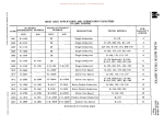
SPECIFICATIONS COVERING HOLLEY CARBURETOR MODEL 1904-FS USED ON SD-220,240 AND BD-269 ENGINES
FUEL SYSTEM SPECIFICATIONS
\0
.".
'"
til
i~
ENGINE MODELS
SD-220
~
CARBURETOR (HOLLEY) MODEL
NUMBER . . . . . . . . . . . . . . . . .
~
"t
~
Q
.
SD-240
BD-269
1904FS
1904FS
1904FS
Use gauge (SE-1772-9MC-145)
Use gauge (SE-1772-9MC-145)
Use gauge (SE-1772-9
MC-145)
Venturi . . . . . . . . . . . . . . . . . .
1-5/16"
1-5/16"
1-5/16"
Main Jet . . . . . . . . . . . . . . . . .
'70 (Std. Alt.)
'70 (Std. Alt.)
If? 3 (High Alt.)
1f?3 (High Alt.)
1f?3 (High Alt.)
Power Jet . . . . . . . . . . . . . . . .
.052-'55 DR.
.043-'57 DR.
.0595-'53 DR. High Speed Bleed . . . . • . . . . . .
.031-'68 DR.
. 031-'68 DR.
.028-'70 DR.
Main Well Bleed-Upper. . . . . . . .
.025-'72 DR.
.025-'72 DR .
.025-'72 DR. Main Well Bleed-Lower. . . . • • .
.025-'72 DR.
.025-'72 DR.
.025-'72 DR .
Idle Well Restriction . • . . . . • . •
.028-'70 DR.
. 028-'70 DR.
.032-'67 DR.
Float Level . . . . . . . . . . . . . . • 'f'
:-
'69 (Std. Alt.)
~ r·
Z
[l"]
Ei:
~
:::0
~
~
{J)
Idle Air Bleed . . . . . . . . . . . . .
.055-'54 DR.
.055-'54 DR.
.0595-'53 DR. Idle Transfer Hole . . . . . . . . . .
. 0465-'56 DR.
.0465-'56 DR.
.0465-#56 DR. Adjust Screw to Obtain
350 to 400 R.P.M.
Adjust Screw to Obtain
350 to 400 R.P.M.
Adjust Screw to Obtain
350 to 400 R.P.M.
Accelerator Pump Spring. . . . . .
38R-452 (.035 Wire)
38R-452 (Wire)
38R-452 (Wire)
Accelerator Pump Link . . . . . . .
33R-207
33R-207
33R-207 Accelerator Jet . . . . . . . . . . . .
.0293-#69 DR.
.0293-'69 DR.
.0293-#69 DR. Fuel Seat . . . . . . . . . . . . . . . .
.082
.082
Used With Governor . . . . . . . . •
Yes
Yes
Idle Adjusting Screw . . . . . . . . . .
~
@
ITj
CflC
'tjPJ
.082
~t'
....
Yes
'U0O< ~CfI
1lI1l1Cf1
(IQ
;::t...,
(001:'1
.... ;~
Donated by John & Susan Hansen - For Personal Use Only
tU~~
:CDCl
CD ° 1:>1
SPECIFICATIONS COVERING HOLLEY CARBURETOR MODEL 1904-H USED ON BD-282 ENGINE
01-3
ENGINE MODELS
BD-282 (Not RC-Trucks)
CARBURETOR (HOLLEY) MODEL NUMBER . . . .
1904H
;1:>1
a:::
Use Gauge (SE-1772-9-MC-145)
Venturi. . . . . . . . • . . . . . . . . . . . . . . . . . . .
Main Jet • . • . • . . • . . . . . . . . . . . . . . . . . . . 1- 3/811
*72 (Std. Alt.) 173 (High Alt.)
Power Jet . . . . . • . . . . . . . . . . • . . . . . . . . .
.050 11
High Speed Bleed . . . . . . • • . . . • . . . . . . . • .
.035-1165 DR. Main Well Bleed - Upper . . • . . . . • . . . . • • . .
.025-*72 DR.
Main Well Bleed - Lower . . . . . . . . . . . . , . . •
.025-1172 DR. Idle Well Restriction. . . • . . • • , , , • . . . , . . .
.031-#68 DR. Idle Air Bleed. , • . . . . . , • , , • . . . . . . , , ..
.055-1154 DR.
Idle Transfer Hole . . . . • . . , , . • . . . . • . . . .
.0465-#56 DR.
Idle Discharge Hole • . . . . . . • . . • . • . . . . • .
.0465-#56 DR.
Idle Adjusting Screw . . . , , . . . . , , . , , . , . . .
Adjust Screw to Obtjiin 350 to
400 R.P.M.
Accelerator Pump Spring, , .•. , . . . . . . • . . .
3!3R-452 (.035 Wire)
Accelerator Pump Link, . , , , •.••. , • • • . . .
33R-207 Accelerator Jet. " . . . • • . , . . . . • , . , , . . , •
.033" Fuel Seat • , , •. , . . • . • . • . . , . . • , . . • . , .
.082" Used With Governor • • . • . • . . • . . . . • . . • • .
Yes
--
°~t-<III
.... III
FUEL SYSTEM SPECIFICATIONS
Float Level . • . . . . . . . . . . • . . • . • . . • . . . .
NSt<
~ Z
[Tl
3:
~:::c ~
~
~
~
E~
Donated by John & Susan Hansen - For Personal Use Only
SPECIFICATIONS COVERING HOLLEY CARBURETOR MODEL 885 FFG USED ON RD-406 AND RD-450 ENGINES
FUEL SYSTEM SPECIFICATIONS
Q
'"
~
~
~:t
~
rn
c
:g
:;
ENGINE MODELS
RD-406 RD-450 CARBURETOR (HOLLEY) MODEL
NUMBER. " . . . . . . . • . . . . . . . . . .
885 FFG 885 FFG Float Level . . . . . . . . . . . . . . . . . . . 1/2" Below Top of Fuel Bowl 1/2" Below Top of Fuel Bowl Venturi. . . . . . . . . . . . . . . . . . . . . . 1-7/32" 1-1/4" g
"g,
E·
'1:1
~
~
q
r;
161 (Std. Alt.) Main Jets . . . . . . . . . . . . . . . . . . . . . #60 (Std. Alt.)
*58 (High Alt.)
159 (High Alt.)
:;0
Idle Tubes . . . . . . . . . . . . . . . . . . . . 54 C.C. Per Min. (.025")
54C.C. Per Min. (.025")
Z
Fuel Inlet Needle Seat . . . . . . . . . . . . .098"
.098"
3::
Adjustable
Adjustable
Power Jet Economizer Valve
*No. 25R-80A-43
*No. 25R-80A-58
Flange . . . . . . . . . . . . . . . . . . . . . . 1-1/4 SAE (Dual)
1-1/4 SAE (Dual)
Idle Adjusting Screws . . • . . . . . . . . . 3/4 to 1-1/4 Turn Open
Main Well Bleed. . . . . . . . . . . . . . . . .025"
.031"
Aspirating Hole . . . • . . . . . . . . . . . . .043"
.067"
Accelerating Jet. . . . . • . • • . . . . . . . .033"
.033"
Idle Air Bleed . . . . . . . . . . . . . . . . . .0465"
.0465" Well Tubes . . . . . . . . . . . . . . . . . . . 3/32" 0.0. 4 Holes .028"
3/32" 0.0. 6 Holes .040" Idle Progression Hole . . . . . . . . . . . . #56 DR. - .0465"
*56 DR. - .0465" Idle Adjusting Hole . • . . . . • . . . . . . . '56 DR. - .0465"
#56 DR. - .0465" ..
C·
~
n
>
Accelerator Pump Plunger Stroke . . . .
*
.040" Wire
.040. 1 Wire
Secondary Venturi . . . . . . . . . . . . . • 3/8" I.D.
3/811 I.D.
Bowl Cover Plate Vent Holes . . . . . . . ."
Only last two digits of number appear on power jet.
2 *18 DR. .,. .1695"
o
d
::0
3/4 to 1-1/4 Turn Open
Accelerator Pump Spring. . • • . . . • . . tr1
~
()
?::
U>
~
~
I'sj
~ct
I1txl
...
nt:-<
~C/)
'tin 0<
I»~C/)
OQ ....
2 #18 DR. - .1695
(Continued)
t-i
l1°txl
I.>J~!J;:
Donated by John & Susan Hansen - For Personal Use Only
'l1C1lIz)
III '1:1 ,..
SPECIFICATIONS COVERING HOLLEY CARBURETOR MODEL 885 FFG USED ON RD-406 AND RD-450 ENGINES
FUEL SYSTEM SPECIFICATIONS - Continued
°Cll
!!...:
.... CIl
o .;
;tzl
-
ENGINE MODELS
RD-406 RD-450
GOVERNOR (HOLLEy) . . . . . . . • . . . . •
885 FFG 885 FFG Yellow Plain Governor Spring Color Marking . • . . .
OQ(1I ....
(1Iotzl
IIl-SI:"'
Governor Spring Position in Housing ..
'3 Perch Position '3 Perch Position
Governor By-Pass Jet (Hole "A") . . . .
.028" .028"
Governor By-Pass Jet (Hole "B") . • . .
.052" .052"
Maximum No-Load Speed. . . • . . . . . .
2950 R.P.M. 2800 R.P.M.
Governor Rotor Valve and Housing
Assembly - IH Part Number . . . . . . . 114510-R9l
1145l0-R91
==
'.'
r
~
s:
~
~
~
~
<
()
tr1
Air Cleaner Oil Capacity Specifications covering the
"Hat" type air cleaner used in conjunction with the
Holley 1904 Carburetor.
SD-220 ENGINE
2 pints
SD-240 ENGINE
BD-269 ENGINE
BD-282 ENGINE 2 pints
2 pints
2 pints -_ __
.........
......
E
Donated by John & Susan Hansen - For Personal Use Only
[;-"
C
--
ENGINE MODELS
z
FUEL SYSTEM SPECIFICATIONS
SD-220
SD-240
,
[1l
BD-269
RD-406
RD-450
Cont. R-6602
1539513
1539513
1538259
FUEL PUMP (AC)
Model mnnber . . . . . . . • . • . . .
Type . . . . . . . . . • . . . . . . . . .
1539537
AF
{3t04_l/Z
lbs. at
3500 engine
r.p.m.
Operating pressure • . . . . . • . . .
1539537
AF
3 to 4-1/2
Ibs. at
,e
3500
r.p.m.
1539501
AT 3 to 4-1/2
Ibs. at
3500 engine
r.p.m.
1539513 .. I;J
"
•
..
4 to 5-1/4
Ibs. at
3600 engine
r.p.m.
"
. ..
'"
.
4 to 5-1/4
Ibs. at
3600 engine
r.p.m.
..
. .
'"
.
4 to 5-1/4
Ibs. at
3600 engine
r.p.m.
. .. ..
"
.
4 to 5-1/4 lbs. at
3600 engine
r.p.m.
$:
o
--l
o
:;0
--l
:;0
C
n
7';
(J)
~
FUEL PUMP (CARTER)
M-737S
Model number . . . . . . . . . . . . .
{ 3 to 4-1/Z
Operating pressure • . . . . . • . • .
lbs. at
3500 engine
r.p.m.
_ _ L-.
-=-......-......-_4'-~
M-737S
3 to 4-1/2
lbs. at
3500 engine
r.p.m.
EXl12-78
3 to 4-1/2
Ibs. at
3500 engine
r.p.m.
.
. .. . .
. .. .. . .
..
..
..
1;1
..
. ..
. .
.. ..
.
"
. ..
.
..
..
.
.. .. ..
.. .. .
. .. . . ..
. ..
.. .. .. .
.. . .. .
.. .. . .
. . .. ..
..
"
..
..
. .. ..
.
.. .. .. .. ..
. . . .. .. . . .. . ..
.. .. . .
..
..
..
.
<
n
[1l $: :P
z
C
:P
r
"'1
enG
"cJ M
~.... l'
......
.... en
><:
'1:l~en
Pl:=;'>-1
ooOM
11> ::I !::"
..... 111;:::.,
Donated by John & Susan Hansen - For Personal Use Only
'l:jUl'Tj
III '"0
C
()QgM
~:::;t:"'
N ... ·
(") Ul
~o-<
.... Ul
FUEL SYSTEM SPECIFICATIONS
ENGINE MODELS
CARBURETOR (CARTER)
Model nUITlber
Float level
Flange, .
Venturi. ,
Main jet.
Idle jet . .
Accelerating jet.
Main air bleed.
Fuel valve seat
Metering rod . .
Idle adjustment
Used with governor.
o
I-j
(II
;g:
::J M
SD-ZZO
SD-240
YF-735-S
Z5/64" (! 1/64")
1-1/4 SAE
1-5/16 11
.104
.OZ76
,OZ5
.034
.076
No. 75-693
3/4 to 1-3/4 turns open
yes
YS-736-S
7/16" (.:!:.1/64")
1-1/4 SAE
1-5/16 11
.1015
,0292
,025
,034
,081
No. 75-688
3/4 to 1-3/4 turns open
yes
r
t
z
fT1
3:
o-;
o
:;:0
-;
:;:0
c
n
7':
(f)
FUEL SYSTEM SPECIFICATIONS
ENGINE MODEL
CARBURETOR (CARTER)
Model nutnber
Float level
Flange . .
Venturi. .
Main jet.
Idle tube.
Accelerating pUITlp jet.
Step-up jet .• ,
Fuel valve seat . . .
Idle adjus tment , , .
Used with governor.
BD-269
BBRI-617SA
5/64" (.:!:.1/64")
1-1/4 SAE
1-5/16"
298 C.C,
.031 .0315 .0374 .086 1/2 to 1-1/2 turns open yes [T1
:;:0
nfT1<
3:
;p,
z
c
;p,
r
Donated by John & Susan Hansen - For Personal Use Only
FUEL SYSTEM SPECIFICATIONS ENGINE MODELS
CARBURETOR (HOLLEY)
Model number
Float level
Venturi. .
Main jets.
Idle tubes.
• ..... .
Bleeder plug or button (in
nozzle bar) . • . . ..
Fuel inlet needle seat . . .
Accelerator pump plunger
stroke . . . . . . . . .
Power jet economizer
valve . . . . . . . . .
Flange . . . . . . . . • • •
Idle adjusting screws
RD-372
RD-406 RD-450 AA-IG
1-1
.059
88 C.C. per min.
852FFG I 1/4" 1-3/16 11 .063 64 C.C. per min. 852FFG 1-1/4" 1-3/16" .061 64 C.C. per min. .175
.098
.234 .098 .234 .098 adjustable adjustable 1- ,
adjustable No. 25R-67A 1-1/4 SAE 3/4 to 1 turn open '~No.
25R-72A-49 1-1/4 SAE (dual) 3/4 to 1 turn open o
d
:::0
~
:::0
C
*No. 25R-72A-66 1-1/4 SAE (dual) 3/4 to 1 turn open n
7':
en
:::0
brown ..
'"
.....
......... ..
.......
. ........ position
in housing.
Governor by-pass jet (hole "A") . . • . . . Governor by-pass jet (hole "B") . . . . . .
Maximum no-load speed
Governor rotor valve and
housing assembly-IH
part number . . . . . . .
$
(T]
GOVERNOR (HOLLEY)
color
........
(Tl
.. .. . . ..
-<n
(T]
$
»
.025 .......... .047 2950 r.p.m. 2925 r.p.m.
2750 r.p.m.
54784-R91 54784-R91
54784-R91
z
c
.........
* Only
last two
»r of number appear on powe r jet.
(Il'rJ
'Oc:M
(1)
r'l
..... t'
~(Il
'tlr'l'-<
>ll>ll(ll
()Q
(1)
::r.1-cl
gM
1JJt!l:S:
Donated by John & Susan Hansen - For Personal Use Only
Donated by John & Susan Hansen - For Personal Use Only
L-UNE MOTOR TRUCK SERVlCE MANUAL
FUEL SYSTEM
Section A
Page I
FUEL SYSTEM-GENERAL VAPOR LOCK
(a) Heat conducted from crankcase and
The Service Parts Department has avail
able an electric fuel pump for use on trucks
which have given trouble with vapor lock, but
they cannot furnish material other than shown
in Fig. 1, because the installation will have to
conform to individual requirements.
(b) Heatreceivedfrom hot oil splashed in
camshaft.
~
Eledric fuel
pump swit,h
~
,
T() coil side of
igniti,," ,witch
~
~I!,--['
~~
I:
I:
H
I
'!!
Carburetor
~i
II
Ii
I!
Mechanical ruel
"
WHEN AND WHY OF VAPOR LOCK
Fig. I
INSTALLATION - ELECTRIC FUEL PUMP
Fig. 1 illustrates a hook-up that is adapt
able to any type of fuel system.
The location of the fuel line from the elect
ric pump should be on the outside of the frame
rail opposite the exhaust system and if neces
sary carried across the front cross member to
the car bur etor .
Considerable freedom can be exercised in
locating the lines, always keeping in mind that
they should be away from the exhaust system
and not exposed to hazards that will result in
their being damaged. The use of loom is rec
ommended where protection from radiated heat
is required.
Should the electric pump be located where
it may be damaged from stones, etc., a simple
shield can be readily installed to supply the
necessary protection.
The following discussion on vapor lock is
for the purpose of providing necessary infor
mation to diagnose and get a solution to the
problem:
WHAT IS VAPOR LOCK?
When a section of the fuel system becomes
filled with gasoline vapor causing either partial
or total disruption of fuel service to the car
buretor, it is said to be vapor-locked.
PRINCIPAL SOURCES OF HEAT - VAPOR
LOCK
The fuel pump is generally the part of the
fuel system where the greatest rise in fuel
temperature occurs because of heat derived
from the following sources:
PRINTED IN UNITED STA.TES
to pump body for lubricating purposes.
(c) Radiated heat from exhaust manifold.
(d) Heat received from under hood air.
It is for these reasons that the electric fuel
pump is mounted on the outside of the frame
rail.
The fuel line from the fuel tank to the reg
ular mechanical pump is under a depression or
more commonly known as suction which lowers
the vaporizing or boiling point of a liquid. This
makes it particularly bad to have it located
close to the exhaust system. By locating the
electric fuel pump close to the fuel tank a
greater percentage of the system is under
pressure, which increases the vaporizing or
boiling temperature of the gasoline.
or
AfoItRICA
Vapor lock occurs in hot weather with a
hot engine when the fuel requirements are at
mlmmum, such as idling after a hard run.
When the maximum amount of fuel is again re
quired, the fuel pump must first expell the va
por during which time the following cycle is
being established:
(a) Reduced engine speed because of lack
of fuel.
(b) Reduced fuel pump speed with propor
tional loss of pumping ability.
(c) Increased fuel temperatures and re
sultant increase in vapor formation
resulting in reduced fuel delivery and
further reduction of engine speed.
The continuation ofthe cycle will1.4ltimately
result in the complete cessation of gasoline de
livery.
TYPE OF FUEL - VAPOR LOCK
The use of a highly volatile gasoline such
as furnished in ItWinter" weather will produce
vapor lock under conditions where a less vola
tile or ItSurn.rnerltgasoline would be satisfactory.
HOW TO DIAGNOSE VAPOR LOCK
A vapor lock in the system permits the
gasoline level in the float bowl to become low
or even dry, causing a lean mixture, which is
evidenced by the following operating character
istics:
(a) Lack of power on full throttle or soft
ness and flat spots on part throttle op
eration.
(b) Stalling on idle when engine is hot.
(c) Inability to start a hot engine.
Donated by John & Susan Hansen - For Personal Use Only
FUEL SYSTEM
Section A
Page 2
L-UNE MOTOR TRUCK SERVICE MANUAL
PROPER USE OF ELECTRIC FUEL PUMP
FOR VAPOR LOCK
When the firs t indications of vapor lock are
observed, the electric pump should be brought
into operation and upon regaining thelostengine
speed, should be shut off, thus giving the s tand
ard mechanical pump an opportunity to rid the
regular fuel system of vapor. This method of
operation may have to be repeated several times
before the mechanical pump will supply suffi
cient fuel, after which the use of the electric
pump is not required; however. in stubborn cas es
continous operation may be necessary. It should
be noted that II shut off" valves are not shown on
the sketch as it is desired tomake the auxiliary
system as flexible as possible to accomodate
either continous or intermittent operation,
making it unnecessary to stop the engine.
NOTE: If the electric pump is not req uired
regularly, it should be operated every few days to
preven t the stagnant gas oline from forming gum.
TRUCK STORAGE - PREPARATION OF
FUEL SYSTEM
When placing trucks in storage remove all
fuel from the fuel sys tem. If fuel is not entirely
removed, a gumlike subs tance will be deposited
on all parts contacted by the fuel, and will seri
ously affect operation of the carburetor and fuel
pump.
All standard grades of gasoline have a
small gum content, which is not sufficient to
cause any trouble under ordinary conditions.
However, when allowed to stand for a period of
two or more weeks, the gum will increase to a
point where a deposit is formed on the surfaces
which it contacts. This deposit, when dry, has
a hard, varnishlike appearance.
Gum deposits may completely alter cali
bration of the carburetor for it will partially or
completely plug the jets or cause the power jet
valve and the accelerating pump to stick. Gum
depos i ts in the fuel pump will caus e the fuel filter
to become clogged or the check valves to stick.
IMPORTANT: It is well to emphasize the
E...ossibilities that can develop because of gum
film in carburetor jets. A thin film of gum
(assume .002" thick) is transparent and would
escape casual inspection; but this thickness of
film represents a .004"
size, and should one or all jets be affected
would be a lean-mixture ratio that would be det
rimental to the engine as well as performance
for it would contribute to sticking and burning
of valves because of gum accumulation O'n the
stems. The condition would also be a contrib
uting cause of premature spark plug failures.
Gum is not soluble in gasoline, therefore any
reduction in the capacity of the jets will be per
petuated almost indefinitely.
The best knownmmean~ of preventing gum
formation in trucks that are to be placed in
storage or allgwed to stand idle for a period of
two or more weeks is to thoroughly condition
the fuel system as follows:
1. Completely drain the fuel tank.
2. Run engine until all fuel is consumed
in carburetor.
3. Remove plug from carburetor under
main jet assembly to complete drain
ing.
4. Empty sediment bowl at fuel pump.
The possible affected parts in the fuel
pump are the check valves and the filtering
screen or filtering element. To determine the
condition of the check valves, remove the caps
from over the valves and test for freedom of
action.
The filtering screen, if in a gummed con
dition, should be replaced and the sediment
bowl cleaned.
If there is doubt as to the condition of the
carburetor, it is suggested that a one-quart
mixture of 50-50 CP acetone and gasoline be
burned through the carburetor at fast idle from
a closed container attached direct to the car
buretor - not through the fuel pump because of
the detrimental effect of acetone on fuel pump
diaphragms. This will serve to remove a large
amount of the gum providing that it has not be
come hard and varnishlike. If the results are
not satisfactory the carburetor must be removed
and all jets and carburetor valves replaced.
FUEL PUMPS
DESCRIPTION
The fuel pump is installed on the engine
between the fuel tank and the carburetor. The
suction side of the pump is connected to the fuel
tank and the discharge side to the carburetor
by tubing designed to carry the fuel. The pur
pose of the pump is to suck fuel from the supply
tank and push it into the ca:t.:buretor float bowl
as it is required by the engine.
OPERATION
The pumping operation is accomplished
through a rockerarm on the pump, contacting
an eccentric on the engine camshaft.
The link is hinged to the rockerarm so that
it can be moved down, but cannot be raised by
the rockerarm. The only function of the rocker
arm spring is to make the rockerarm follow the
cam. The link and diaphragm are moved by the
diaphragm spring. The pump, therefore, de
livers fuel to the carburetor only when the fuel
pressure in the outlet line is less than the pres
sure maintained by the diaphragm spring. This
condition arises when the float needle valve is
not seated and the fuel passage from the pump
into the carburetor float chamber is open. When
the needle valve in the carburetor float chamber
is clo-sed, and held in place by the pressure of
the fuel on the float, the pump builds up pres
sure until it overcomes the diaphragm spring.
This pressure results in almost a complete
stoppage of diaphragm movement until further
fuel is needed.
Donated by John & Susan Hansen - For Personal Use Only
L-L1NE MOTOR TRUCK SERVICE MANUAL
FUEL SYSTEM
Section A
Page 3
HOW TO DIAGNOSE FUEL PUMP TROUBLE
ENGINE GETTING TOO MUCH GAS:
Fuel pump trouble is of only two kinds.
Either the pump is supplying too little gas
or, in rare cases, too much.
More often than not, an oversupply of gas
oline is caused by trouble somewhere else - not
in the pump. So, first check the following:
If the pump is supplying too little gas, the
engine either will not run at all, or will cough
and falter.
1. Defective automatic choke.
2. Excessive use of hand choke.
3. Punctured carburetor float.
If the pump is supplying too much gas, you
will be able to see gasoline dripping from the
carburetor; or the engine will not run smoothly
when idling.
s are hard to start when
getting too much gas.
LOCATING FUEL PUMP TROUBLE
AL WAYS CHECK WHILE THE PUMP IS
INSTALLED ON THE ENGINE. DON'T TAKE
IT OFF TO CHECK IT.
ENGINE NOT GETTING ENOUGH GAS:
If the engine is getting too little gas, the
trouble may be in the pump, the fuel line: or
the gas tank.
First, be sure that there is gas in the tank.
Disconnect the outlet line from the pump,
or the carburetor, whichever is easier to reach.
Then, turn the engine over a few times, using
the starting motor. It is be st to turn off the ig
nition switch.
If gas spurts from the pump or the outline
line, the pump, gas line, and tank are OK.
If no gas flows at all, or if only alittle gas
flows, do the following:
1. Look for a leaky bowl gasketseat. In
stall a new gasket if you are not sure.
2. Remove and clean the gas strainer
which is inside the pump bowl.
3. Look for loose line connections. Check
Tighten
4. Look for a clogged fuel line. Blowout
with compres'sed air.
5, Make sure that all cover screws on
the pump are tight. Make sure that
the external plugs over pump valves
are tight.
6, Inspect the flexible fuel line for breaks
or porous condition.
If correction of the above six items does
not place the pump in operating condition, it
should be removed for replacement or overhaul.
PRINT£D IN UNI'fE:O S'fA'tES OF AMERICA
4. Defective carburetor needle valve.
5. Loosely connected fuel line, or loose
carburetor assembly screws.
6. Improper carburetor adjustment.
NOTE: If none of these is the cause of
flooding or poor gasoline mileage, then the
pump needs overhauling.
FINAL CHECK:
After overhauling, a simple check of the
suction and pres sure should be made before in
stalling the pump on the engine. This can be.
done by holding the fingers over the inlet and
outlet openings of the pump and manipulating
the rockerarm by hand. The pump may then be
reinstalled on the engine and tested. (See in
stallation instructions below). It should prime
itself, that is, fill the filter bowl, in about 30
seconds with the starter button depressed. If
it fails to provide sufficient pressure, the dia
phragm has been incorrectly installed, prevent
ing the full stroke of the push rod, or the springs
do not have sufficient tension: and it will be
necessary to disassemble the pump to reinstall
the diaphragm correctly or to replace the link
age springs if this has not been done.
INSTALLATION OF FUEL PUMP
Use a new gasket between fuel pump mount
ing flange and pad' on c rankc as e and tighten cap
screws securely.
Connect fuel lines, first making sure that
there is no dirt on the fittings which might be
drawn into the system.
If carburetor has not been removed there
will usually be sufficient fuel in it to run the
engine long enough to fill the fuel pump filter
bowl. If there is an air leak between filter bowl
and gasket, the pump cannot draw fuel into the
bowl. To remedy this, install a new gasket and
see that bowl seats squarely. Tighten clamp
screw securely with the fingers only.
If fuel pump bowl still doe s not fill, the
trouble may be due to an air-bound condition.
In this case the bowl should be loosened slightly
so that air can escape and, by blowing in the
gasoline tank filler neck, fuel will be forced
into the pump. Then tighten bowl securely and
start engine.
Donated by John & Susan Hansen - For Personal Use Only
Donated by John & Susan Hansen - For Personal Use Only
L-LlNE MOTOR TRUCK SERVICE MANUAL
FUEL SYSTEM
Section B
Page 1
CARTER MODEL-YF CARBURETOR
Description
The Carter carburetor model YF for the 220
and 240 Silver Diamond engines is essentially
the same as conventional carburetors in that
it has a high-speed fuel circuit, low-spleed cir
cuit, and accelerating pump circuit.
There is, however, a departure in the metho'd
of controlling the fuel flow on part-throttle,
wide-open-throttle and through the accelerating
pump circuit as compared to carburetors pre
viously used. A calibrated metering rod (Fig. 4)
fits into the main jet. It becomes effective at
low-part-throttle speeds and automatically
positions itself according to the throttle opening
thus producing proper fuel flow throughout part
throttle and wide-open-throttle.
identifying the various assemblies when dis
mantling the YF model carburetor for complete
reconditioning. as outlined in the following step
by-step instructions.
~"'f----
Air horn'
and fuel
bowl cover
lever
The heart of the carburetor is the diaphragm
(Fig. 4) which actuates the accelerating pump
and the step-up action for wide-open-throttle
fuel mixtures.
The underside of the diaphragm is subjected to
manifold vacuum by means of a channel down
to the carburetor flange. This channel is re
stricted by a bushing in the flange in order to ob
tain consistent and smooth performance and to
promote extra long diaphragm life.
lever
Any movement of the diaphragm results in a
corresponding movement of the metering rod.
When the throttle is wide open the manifold
vacuum drops sufficiently to allow the diaphragm
to move upward thus shifting the metering rod to
the wide open throttle step.
A chamber above the top of the diaphragm sup
plies fuel for the accelerating pump circuit.
The diaphragm acts as a pump and the quantity
of fuel discharged by the pump is controlled by
the size of the pump jet or nozzle calibration
(Fig. 2) and also the size of the fuel inlet hole to
the chamber. There is no check valve on the in
let. There is a check valve in the outlet channel
near the pump jet to allow fuel to pass in an out
ward direction only and also to prevent air from
being sucked back into the chamber under cer
tain conditions. The pump jet is free to flow at
all times generally starting at a part-throttle
engine speed of 1500 r.p.m. and continuing
throughout wide-open-throttle.
A-22880
Fig. I - Carter (Model YF) Carburetor
Low-speed or idling jet
Pump disc retainer ring
This carburetor has a unique feature in that no
change in setting is required when it is used in
conjunction with a sandwich type governor, re
gardless of whether or not a vacuum by-pass is
used around the governor.
Illustrations (Figs. I to 8) show the location of
the various parts. and will aid in correctly
PRINTED IN' UNITED STATES OF AMERICA
Fig. 2
Donated by John & Susan Hansen - For Personal Use Only
FUEL SYSTEM
Section B
Page 2
L-LINE MOTOR TRUCK SERVICE MANUAL
Throttle
lever
stop
A-22900
Fig. 3
Fig. 6
Upper
pump
sp!ing
Pump intake,_"_ __
strainer
Throttle
shaft
Pump Iifter.___-lIo>
link"
A.22899
A-22902
Fig.
Fig. 7
Ij
Choke
Choke
valve
A-22974
Fig. 5
Fig. 8
Donated by John & Susan Hansen - For Personal Use Only
L-LINE MOTOR TRUCK SERVICE MANUAL
MODEL YF - SERVICE PROCEDURE
To Disassemble
1. ReITlove pin springs, fast idle connector
rod spring, and rod (Fig. 1).
2. ReITlove air horn and bowl cover attaching
screws (7), and choke tube claITlp asseITlbly
(Fig. 1).
3. ReITlove air horn asseITlbly, and gasket.
4, ReITlove pUITlP disc retainer ring (using
knife tip), retainer, and pUITlP check disc
(Fig. 2).
5. ReITlove throttle shaft arITl asseITlbly, pUITlP
connector link, shaft seal spring, dust seal
washer, and felt dust seal (Fig. 7).
6. Loosen diaphragITl housing attaching screw,
and washer assemblies (4) and lift out entire
pUITlP and ITletering rod asseITlbly (Figs.
3 and 4).
7. RelTIOve diaphragITl housing attaching screws,
pin spring, ITletering rod upper pUITlP spring
retainer, upper pump spring, metering rod
arm assembly, and pUITlp lifter link (Fig. 4).
8. ReITlove diaphragITl spring retainer, spring,
and pUITlP diaphragITl asseITlbly (Fig. 4).
9. Carefully reITlove pUITlP intake strainer from
housing, using tip of knife blade.
10. Remove metering rod jet.
11. Remove low-speed (idle) jet asseITlbly.
Do not remove pressed in parts such as
nozzle, pump jet or anti-percolator air
bleed. (Fig. 2).
12. Remove body flange attaching screw (3),
body flange assembly, and gasket (Fig. 1).
13. ReITlove idle adjustITlent screw, spring,
idle port rivet plug, throttle lever assembly,
washer, fast-idle arm, valve attaching
screws (2), and throttle shaft. Then remove
throttle shaft seal by prying out seal re
tainer. Do not remove vacuum passage
orifice (pre s sed in).
14. Remove float pin, float, and needle and
seat assembly from air horn casting (Fig. 5).
15. RelTIOve choke valve screws and choke valve.
Unhook choke spring and slide shaft from
housing. Do not remove balance vent tube.
NOT E: In normal service, choke lever
assembly will not require replacing. How
ever, if it has been bent or otherwise
damaged requiring replaceITlent, proceed
as follows: Pry off choke lever retainer
ring and remove lever assembly (Fig. 8).
PRINTED IN uNITED STATES OF AMERICA
FUEL SYSTEM
Section B
Page 3
16. Wash all parts in carburetor cleaning
solution and blowout passages with com
pressed air. Do not immerse diaphragm
assembly, PUITlE check disc or seals in
cleaning solution. Inspect all parts for
wear or damage and replace if necessary.
Always use new gaskets.
To Reassemble
17. Group all parts, controlling the float cir
cuit: float, float pin, needle and seat as
seITlbly, air horn gasket.
18. Group all parts, controlling the low-speed
circuit: throttle shaft seals (2), and re
tainers (2), throttle shaft, throttle valve
and screws, fast-idle arITl, throttle shaft
washer, throttle lever, idle port rivet plug,
idle adjusting screw and spring, gasket,
attaching screws (3), low-speed jet, throttle
shaft seal spring.
19. Group all parts, controlling the high-speed
circuit: Metering rod, metering rod jet,
pin spring.
20. Group all parts, controlling the pump cir
cuit: pUITlp lifter link, .FUITlp connector link,
throttle shaft arITl assembly, metering rod
arITl asseITlbly, pump diaphragm housing,
pUITlp diaphragITl assembly, pUITlp diaphragm
spring, diaphragITl spring retainer, pump
intake strainer, upper pump spring, upper
pump spring retainer, pUITlP disc check,
pump disc retainer, pUITlp disc retainer ring,
diaphragm housing screw and washer as
sembly (4).
21. Group all parts, controlling the choke cir
cuit: choke valve and screws (2), choke shaft
and lever as s eITlbly , fast-idle connector rod
and spring, choke tube clamp asseITlbly, air
horn attaching screw and washer assembly
(7), pin spring (2).
22. Install throttle shaft seal and retainer in
flange casting.
23. Install fast-idle arm, washer and lever as
seITlbly on thr ottle shaft; slide shaft into
place and install throttle valve. Carter
trademark should go toward the idle port.
when viewed from manifold side of flange.
Tap valve and hold in place with finger be
fore tightening screws.
24. Install idle port rivet plug and idle adjusting
screw and spring.
25. Attach flange assembly to body casting.
Use new gasket.
26. Install low-speed jet assembly.
Donated by John & Susan Hansen - For Personal Use Only
FUEL SYSTEM
Section B
Page 4
L-UNE MOTOR TRUCK SERVICE MANUAL
27. Install pUrrlp intake strainer in pUrrlp dia
phragrrl housing and carefully press into
recess. CAUTION: If strainer is even
slightly darrlaged, a new one rrlust be used.
28. Install pUrrlp diaphragrrl asserrlbly in dia
phragrrl housing, then install pUrrlp dia
phragrrl spring (lower) and retainer.
29. Install pUrrlp lifter link, rrletering rod arrrl,
upper pUrrlp spring and retainer.
30. Install rrletering rod jet; no gasket is used
with this jet.
31. Install diaphragrrl housing attaching screws
(4) in the diaphragrrl housing, rrlaking sure
the edges of diaphragrrl are not wrinkled.
Lower into place and tighten screws evenly
and securely.
32. Install throttle shaft seal, dust seal washer,
and shaft seal spring.
33. Install pUrrlp connector link in the throttle
shaft arrrl asserrlbly. Install throttle shaft
arrrl asserrlbly on throttle shaft, guiding
connector link into pUrrlp lifter link hole.
CAUTION: Linkage rrlust not bind in any
throttle position. If binding occurs, loosen
clarrlp screw in throttle arrrl, adjust slightly
and retighten screw.
34. Install pUrrlp check disc, disc retainer, and
lock ring.
35. Install rrletering rod, and pin spring. Con
nect rrletering rod spring.
36. Metering Rod Adjustrrlent: Be sure flat
of rrleter ing rod arrrl is parallel to flat of
pUrrlp connector link before proceeding with
rrletering rod adjustrrlent. With throttle valve
seated, press down on upper end of diaphragrrl
shaft. Metering rod should be seated in cast
ing and rrletering rod arrrl (Fig. 3) flat
against pUrrlp lifter link (A). If rrletering rod
does not seat in body casting (check by
pressing downward on rrletering rod) or
seats before the rrletering rod arrrl rrlakes
flat contact with pUrrlp lifter link. raise or
lower by bending lip (B) on rrletering rod
arrrl. Adjust float level as shown in Fig. 3.
Width of gauge is 25/64" for YF-735S car
buretor and 7/16" for YF-736S carburetor.
A tolerance of plus or rrlinus 1/64" is per
rrlissable in each float level setting.
37. Install needle seat and gasket asserrlbly,
needle, float and float pin. NOTE: Stop
shoulder on float pin rrlust be on side away
frorrl bore oJ carbure tor.
38. Set float level to catalog page specifications.
Measure frorrl rrlachined surface of casting
(gasket rerrloved). Adjust by bending lip
which contacts needle.
39. Install air horn gasket and air horn as
serrlbly. Install attaching screws and lock
washers (7) and choke tube c1arrlp asserrlbly.
(Tighten center screws first.)
40. Slide choke shaft and lever asserrlbly into
place and connect choke lever spring. In
stall choke valve. Center valves by tapping
lightly and hold in place with fingers when
tightening screws.
41. Install fast-idle connector rod with offset
portion of the rod to top of pin spring to the
outside. Install fast-idle connecting rod
spring.
Donated by John & Susan Hansen - For Personal Use Only
L-LlNE MOTOR TRUCK SERVICE MANUAL
FUEL SYSTEM
Section C
Page 1
CARTER MODEL BBR-l CARBURETOR
(FOR DETAILED DISASSEMBLY INSTRUCTIONS SEE SHOP TALK NO. 35)
Float setting
Idle
1If----Flaoge assemhly
A. I 7083
Fig. I
Description
Fig. 2 - Before adjusting float level, be sure
float lever pin is firmly seated and that the
float pin retainer is in position. Reset float
level by bending I ip of float lever away from
needle to raise level, or toward needle to lower
float level. Bend vertical lip of float only.
Use float gauge (SE-1639-IO) and check level as
shown. Setting is 5/6~" plus 1/6~n below top
surface of carburetor body casting and without
the body gasket.
Idle adjusting The Carter Model BBR-l-617SA carbur
etor (Fig. l) is a downdraft carburetor, divided
into five circuits which consist of the following:
screw }1
to
1}1
turns FLOAT CIRCUIT
The float circuit controls the height of the
gasoline level in the bowl (Fig. 2). A gasoline
level too high or too low may cause trouble in
other circuits, and make complaints hard to
trace.
The float circuit consists of a needle valve,
seat and gasket, float, float bowl, float bowl
cover, float lever, pin retainer, float pin, gasket
and vent hole.
Fig. 3 - Idle adjustment is ! to I! turns open.
For richer mixture, turn the idle screw out.
LOW -SPEED CIRC UIT
orifice tube and plug assembly, air bleed, idle
port, idle mixture adjusting screw, throttle
valve, carburetor bore, and economizer.
The idle or low-speed circuit controls the
supply of gasoline to the engine during idle and
no-load up to a speed of approximately 15 to 20
m.p.h. and it partially controls the supply of
fuel for no-load or light loads at higher speeds
(Fig. 3).
HIGH-SPEED CIRCUIT
The intermediate and high-speed circuit
consists of the step-up jet, step-up piston and
rod assembly, main metering jet, main vent
tube, diffuser holes, and air passage.
The low-speed circuit consists of the idle
PRINTEO IN UNITED STATE'S OF AMERleA
PUMP CIRCUIT
The acceleration circuit consists of the
Donated by John & Susan Hansen - For Personal Use Only
FUEL SYSTEM
Section C
2
L-UNE MOTOR TRUCK SERVICE MANUAL
accelerating pump spring, pump plunger and
rod assembly, pump leather, inlet valve, outlet
valve, pump jet air bleed. and pump jet.
11
The accelerating pump is provided with an
adjustable stroke setting. Set the accelerator
link in the inne r hole in the throttle shaft leve r
For
r setting. use
12
CHOKE CIRCUIT
This circuit is used only in starting and
warming a motor, its purpose being to supply
a rich mixture temporarily. It consists of a
choke shaft and lever assembly, a choke valve,
choke breather valve and spring, and a means
of controlling the position of the valve. It incor
porates a fast idle cam connected to the choke
shaft by a rod. When the choke is closed the
throttle valve is forc ed open slightly by the cam
to make starting easier and prevent stalling.
The choke breather valve allows sufficient
air to enter so that the motor will start and not
flood even though the choke valve is fullyc1osed.
Carburetor Overhaul
(See Shop TalkNo. 35 for complete instruc
tions and details ).
When disassembling the carburetor keep
the various groups of circuit parts together so
that each group can be inspected and replaced
completely before proceeding to the next group.
Use a sectionalized pan or muffin tin to sepa
rate each group of parts.
Reassembly of the carburetor is practi
cally the reverse of disassembly. A complete
set of servicing tools is provided to facilitate
overhauling of the Carter carburetors. These
tools are available under SE-1639, and are
shown in Fig. 4.
Proper selection of carburetor flange gas
ket is necessary when installing the carburetor
on the manifold, see Fig. 5. U the carburetor
is used in conjunction with a sandwich governor
(governor mounted between carburetor
and manifold), the gasket having four
holes is used. Where no governor is used the
slotted gasket is used. The slots in the gasket
provide leads to the vacuum passage leading to
the step-up piston cylinder. Either gasket can
be used between the governor and manifold.
4
3
z
1
Fig. 4 - Service Tools (See list belOW)
5
Service Tools
A special set of tools is provided to facil
itate overhauling of the Carter carburetors,
(see Fig. 4). These tools are as follows:
SE-1639 Carter Carburetor Service Tools.
Set consists of SE-1639-1 to 1639-13
inclusive:
SE-1639-1 Grip handle for sockets (No. T
109-51)
SE-1639-2 Handle bar for grip handle (No.
T 109-53)
SE-1639-3 Screw driver bit 5/16" (No. T
109-57)
SE-1639-4 Screwdriver bit 11411 (No. T109
58)
SE-1639-5 Screw driver bit 3116" (No. T
109-59)
SE-1639-6 Socket, double hex, 9116" (No.
T109-69)
SE-1639-7 Socket, double hex, 5116" (No.
T 109-64)
SE-1639-8 Ball retaining ring inserter
tool (No. T 109-75)
SE-1639-9 Rivet extractor tool (No. TI09
43)
SE-16 39-1 0 Floatlevel gauge (No. T 109-50)
SE-1639-ll Main vent tube tool (No. T 1 09
195)
SE-1639-12 Ball retaining ring removing
tool (No. TI09-56)
SE-1639-13 Metal box for SE- 1639 tools.
Carburetor flange gaskets
Used without governor
Used with governor
"'-23443
Fig. 5
Donated by John & Susan Hansen - For Personal Use Only
L-UNE MOTOR TRUCK SERVICE MANUAL
FUEL SYSTEM
Section D
Page 1
HOllY MODEL 852-FFG CARBURETOR Idle adjusting
screws
Throttle stop
screw
A-22549
Fi g. 2
Fig. I
Description
plates and a separate main metering system and
idle system, one for each side.
The Holley Model 852-FFG carburetor is a dual
downdraft carburetor of the plain tube type,
designed for use on engines of approximately'
260 to 390 cubic inch displacement. All of the
metering jets and passages are located in the
center of the main body, which provides for
correct metering of fuel and air at all practical
operating angles. The carburetor fuel system
is fully balanced and sealed, the air for all
vents and bleeds being taken from the main air
entrance of the carburetor, thus, only air which
has passed through the air cleaner is admitted
to the carburetor.
The governor actuated throttle mechanism is
an integral part of the carburetor. designed to
provide the needed power required for moving
the throttle to governing speeds and is con
trolled by a separately driven governor rotor.
The combination of these two units has been
engineered to give instant response and accurate
governing.
A power valve provides addition3-l fuel for high
power operation, and a throttle actuated ac
celerating pump provides the necessary fuel for
fast engine pick-up.
A throttle lever which is self-locking and self
positioning is incorporated in this carburetor.
This dual carburetor can be considered as two
carburetors built into one unit. There are
separate venturi tubes, idle tubes and throttle
PRINTJ;:.D IN UNITED S"I"A"rE$ 01" AMERICA
NOTE: In the following explanations, one side
is generally referred to, unless mentioned
otherwise.
Idle Fuel System
The fuel from the carburetor bowl (12) passes
through the main metering jet (13) into the idle
tube (10) as shown in Fig. 2. Air is introduced
into the fuel stream by idle air bleed (8). This
fuel and air mixture then travels through the
idle passage (1) through the chamber' around the
bleeder plug (16) and to the continuation of
passage (1) then discharges at idle transfer hole
(2) and idle discharge hole (3).
When the engine is set to idle at a speed of
approximately 350 r.p.m. the mixture is dis
charged out of the lower hole (3) only. As the
throttle plate (5) is opened and the engine speed
and air flow increases, the upper idle trans
fer hole (2) starts discharging in addition to the
lower hole at about 450 r.p.m. The action and
timing are such that the discharge from the
upper hole reaches a maximum at approximately
750 r.p.m. and then gradually becomes less
effective as the main nozzle (15) begins to flow.
The lower discharge hole (3) is provided with an
idle adjusting needle (4). Turning this needle
out (to the left) gives a richer mixture and turn
ing in (to the right) a leaner mixture. The idle
adjustment should be set with a vacuum gauge
for the highest and steadiest vacuum reading or
Donated by John & Susan Hansen - For Personal Use Only
FUEL SYSTEM
Section D
Page Z
L-UNE MOTOR TRUCK SERVICE MANUAL
At idle the vacuurn is the highest, and it de
creases as the load of the
increases.
The piston (18) (actuated by vacuurn) and the
spring (19) are held in the "up" position which
allows the valve (17) to rernain closed until the
vacuurn drops to approxitnately 7.5 to 6.5 inches
of rnercury. Below this vacuurn the piston force
is not great enough to resist the compressed
load of the spring (19) and thus opens the power
valve (17).
.... ~
27-~-h
11....,....,-'--;- 28
25
(
Under load, as in clirnbing hills, etc., the vacuurn
drops because it becomes necessary to open the
throttle wider in order to rnaintain speed. When
the vacuurn drops below 7.5 inches of rnercury.
the power valve is opened by the piston stern.
The fuel then flows into the power valve chamber
and through the restriction (Zl) into the rnain
well (6), and is discharged together with fuel
frorn the rnain rnetering systern. This gives the
additional fuel required for high speeds for
heavy loads and low speeds at full throttle.
Accelerating Pump
A-22471
Fig. 3
the srrlOothest running and rnaxirrlUrn idle r.p.rn.
When seating the idle adjustrnent needle (4),
excessive force should never be used as this rnay
cause a groove to forrn on the needle point. If
this occurs, the adjusting needle will have to be
replaced in order to obtain a satisfactory idle
adjustrnent.
Main Fuel System
As the throttle is opened and the idle systern
becornes less effective, the rnain discharge
nozzle (15) in Fig. Z starts to deliver fueL
This occurs at approxirnately 900 r.p.rn. road
load. Between 900 and 1 ZOO r .p.rn., there is a
definite blending of the idle and rnain fuel systern.
In the above range all the fuel passes through the
rnain jet (13) up through the rnain well (6) to
angle channel (9). Here the fuel is atornized by
the high speed bleed (7). and an additional sup
ply of air is introduced to this rnixture by the
bleeder plug (16) before being discharged through
the vertical passage (14) into the venturi.
The float bowl (lZ), Fig. Z, is vented to the
atrnosphere through a balance tube (34). This
systern, besides correcting float charnber air
pressure for atrnospheric changes, keeps dirt out
of the fuel systern and reduces air cleaner
cIo g g ing e He c ts to a rn inirnurn.
The accelerating purnp shown in Fig. 3 is con
nected to the throttle shaft by rneans of link
(33) and operating lever (3Z). The function of
the accelerating assernbly is to ternporarily en
rich the rnixture for rapid acceleration. The
fuel is drawn into the pump charnber (Z9) through
pump inlet check valve (Z5) on the upward stroke
of pump piston (30) when closing the throttle.
When the throttle is opened, the pump piston
(30) moves downward. closing the pump check
valve (25) and forcing the displaced fuel through
passage (Z4) to raise the purnp discharge valve
(Z8). The accelerating fuel charge then goes
around the valve and out the purnp discharge
nozzle (Z6).
A slot in the pump piston stern allows the purnp
operating rod (31) to overrun the purnp piston
(30) when the throttle is opened suddenly. This
overrun causes the purnp piston to be subjected
to the pressure of the spring (Z7), thereby giving
a prolonged discharge of the accelerating fuel.
The accelerating purnp is provided with an ad
justrnent for varying the quantity of the accel
erating charge. This adjustrnent is rnade by
changing the position of the purnp link (30) in
the holes of the operating lever (3Z). The
position farthest away frorn the pivot point is
the cold weather setting since it gives the
greatest discharge. The rniddle position is the
average setting, and the position nearest the
pivot is used under conditions of very hot weather.
POWER MIXTURE SUPP L Y
The power valve vacuurn piston (18) and the spring
(19) shown in Fig. Z are actuated by the vacuUITl
below the throttle plate (5) which cOITlITlunicates
with the top of the piston (18) through pas sage
. (20).
ADJUSTMENTS AND SERVICE HINTS
TOOLS REQUIRED - This carburetor can be
cleaned or repaired without the use of special
tools.
Donated by John & Susan Hansen - For Personal Use Only
L-UNE MOTOR TRUCK SERVICE MANUAL
FUEL SYSTEM
Section D
Page 3
cover raises the level; pushing it away from
the cover lowers the level,
NOTE: The fuel inlet valve, valve seat, and
gasket are serviced as an assembly and should
be used as supplied in factory :matched sets.
When replacing the valve seat, be sure to use
a screwdriver with a blade wide and heavy
enough to fill the slots in the valve seat.
IDLING SPEED ADJUSTMENT - First set the
idling speed by adjusting the throttle stop screw,
(Fig. 5).
The idle :mixture is controlled by the idle ad
justing screws (Fig. 5),
Fig.
~
Before making any adjustments to the carburetor,
it is important that the breaker points and spark
plugs be properly spaced, the ignition timing cor
rect and valve tappets set to proper clearance.
Check all carburetor asse:mbly screws and mani
fold flange bolts, see that they are thoroughly
tightened and that there are no leaks at gaskets.
FLOAT LEVEL - Proper carburetor perfor
:mance is dependent on :maintaining the correct
fuel level in the bowl. The float level can be
set accurately, when the air horn is off, by
gauging the distance between the botto:m of the
float and the flange surface of the air horn.
Holding the air horn upside down, less gasket,
and with the float in the closed position, :measure
the distance fro:m the flange surface of the
air horn to what would nor:mally be the botto:m
side of the float, not the soldered sea:m (Fig. 4).
The correct distance that it should :measure is
1-11/32". To correct the float setting, the float
lever ar:m (11), Fig. 2, should be bent up or down
to bring the float within the established limits
and thus correct the fuel level for best opera
tion. Pushing the float toward the float cha:mber
'"..,y
I
NOTE: These screws regulate fuel flow and are
not air bleed needles. Tur
these screws
in (or to the right) :makes the :mixture lEraner,
and turning the:m out (or to the left) :makes the
:mixture richer. Screws should be turned in until
they just touch the seat, then backed off one full
turn. Care should be taken not to ja:m the screws
agains t the s eat tight enough to groove the
points. If this occurs, the needles will have to be
replaced before a satisfactory adjust:ment can
be :made. The screws should be adjusted with
the fingers to avoid da:mage.
When the engine has war:med up, turn both idle
screws in until the engine starts to slow down,
then turn both idle screws out until the engine
starts to slow down. A point half way between
these two will be very close to the correct idle
:mixture.
After arriving at the correct :mixture, it :may
be necessary to reset the throttle stop screw
to obtain the correct idle speed. Changing the
speed :may :make a slight change in the idling
:mixture. In the event this occurs, re-adjust
the s crews as outlined above.
NOTE: When adjusting the idle :mixture it is
i:mportant that both idle screws be set at ap
proxi:mately the sa:me nu:mber of turns open,
otherwise, the off idle perfor:mance :may be
erratic.
FAILURE TO IDLE PROPERLY AFTER AD
JUSTING - Be sure :motor is tuned to speci
fications. Check for air leaks in intake :mani
fold gaskets, carburetor body, bowl and flange
gaskets.
"~'I
II
"nl
i
Throttle lever ',,
stop screw A-22241
screws
Fi g. 5
PRINTEO IN UNITEO STATES 0'" .....n:;~lc ...
If the idle is erratic and not sensitive to ad
just:ment, check the float level in the float bowl.
Check the idle tubes (10). They :must be tight
on seat in nozzle bar casting (15), Fig. 2.
ACCELERATING PUMP ADJUSTMENT - When
the engine does not accelerate properly, check
the accelerating pu:mp syste:m for dirt. If the
pu:mp inlet check valve (25), Fig. 3, does not
seat, fuel will return to the float bowl instead
Donated by John & Susan Hansen - For Personal Use Only
FUEL SYSTEM
Section D
Page 4
L-UNE MOTOR TRUCK SERVICE MANUAL
of dis cha r ging through the pump dischar ge
passages (26). This can be checked by re
moving the main body cover and operating the
pump with a small amount of fuel in the bowl.
If the check ball is leaking, air or fuel will
bubble back into the float bowl through the inlet
hole. After cleaning this seat, extreme care
should be taken when reinstalling the pump
piston to be sure the piston leather is not damaged
and that it contacts the cylinder wall. If the
leather is not a snug fit against the cylinder wall,
fuel will leak by the piston on acceleration,
causing a weak discharge.
To clean the accelerating pump system, remove
piston assembly and check ball retainer and check
ball from bottom of cylinder. Remove pump
discharge nozzle, and valve (28) Fig. 3. Re
move pump discharge needle valve. All chan
nels can then be cleaned of all foreign matter
by flowing out with compressed air. The small
holes or restrictionsin the discharge nozzle
should deliver a fine, solid and round stream.
When the system is in good condition, a quick
steady stream will flow from the discharge out
let the instant the throttle is opened.
MAIN FUEL SYSTEM - To check for trouble at
intermediate speeds, be sure all gaskets are tight.
Remove main jets (13) Fig. 2, and check size in
accordance with specifications.
Clean main
jets, main jet passages and main discharge
nozzle with compressed air.
2. Remove the main jets using a screw driver
having a screw starter blade. See Fig. 39.
NOTE: If the jet fails to stick to the end of
the removing tool, but falls off into the fuel
bowl, it may be necessary to remove the air
horn assembly.
3. Install the main jets in the reverse of the
removal operation. No gaskets are used with
the main jets.
NOTE: Do not try to change the size of the
power valve restriction (21) Fig. 2, or the
pump discharge nozzles (26) Fig. 3, as this
will cause erratic performance.
ECONOMY COMPLAINTS - Changing jets rarely
increases economy more than slightly and often
ruins performance. Make a thorough check
on the condition of the motor with a compression
gauge and make sure valves are in good condition.
In a vehicle, check for dragging brakes or extra
friction. Do not merely take a customer's word
on mileage; run a gas test with a scientific
mileage tester. Check float level in carburetor
bowl and make sure the fuel pump pressure is
not excessive. Then, if there is still cause for
complaint, the various points as outlined above
should be carefully checked over.
NOTE: Never attempt to clean any of the small
holes or restrictions by forcing any object
through them. This is apt to enlarge the hole
or distort the shape and change the calibration.
HIGH SPEED COMPLAINTS - For high speed
complaints, check the power valve (17), Fig. 2,
as well as the main jets (13) in accordance
with the above instructions. Clean all passages
with compressed air. Check the fuel pump
pressure to be sure it is sufficient to maintain
fuel level in the bowl. Check float travel to
insure full opening of the inlet valve.
ALTITUDE OPERATION - In some cases in
high altitudes, it may be necessary to use leaner
metered main jets. Usually a 5% or 10% leaner
jet will compensate for any variation in altitude.
The metering jets are .marked in thousandths
of an inch of hole diameter; thus, the smaller
the hole, the smaller the number on the Jet.
The main jets can be removed and installed
without disas sembling or removing the car
buretor from the engine in the following manner:
1. Remove the two main jet passage plugs
and gaskets from the car bur etor main body.
Removal of thes e plugs will drain the fuel
bowl. See Fig. 38.
Fig. 6 - Showing adjustment provided for accel
erating pump stroke. Ho. I hole shortens pump
stroke. No.2 length-increases pump stroke,
The No.2 hole is the intermediate and recom
mended position,
GOVERNOR - MODEL 1174
This engine speed governor has been designed
and engineered as an integral part of the Holley
Carburetor. The governor is a vacuum con
trolled device featuring all the advantages of a
Donated by John & Susan Hansen - For Personal Use Only
L-LINE MOTOR TRUCK SERVICE MANUAL
Fig. 7 - Detai Is of governor.
FUEL SYSTEM
Section D
Page 5
Spinner or rotor housing is located at distributor,
mechanical governor without resorting to
lengthy and complicated linkage. The governor
can be cleaned and serviced without the use of
s})ecial tools,
The governor is made up of two units (see Fig. 7).
The control at the engine end of the governor
consists of a governor valve (47), an adjusting
screw (48) and a spring (49) assembled i:r: a
rotor (41) which revolves at one half the eng~ne
speed, in a housing (52), attached to an engme
driven shaft (43). The controls at the carburetor
end of the governor unit consist of a diaphragm
(35) which is connected to the goverl1or lever
(45) by a short rod and a tension spring (46)
which is also attached to the governor lever (45)
and tends to hold the throttle open.
The diaphragm chamber (33) in Fig. 9 is con
'nected to the governor valve air bleed orifice
(50) in Fig. 7 by means of a c onve ntional pipe
line (34). The air bleed supply enters the rotor
housing (52), Fig. 7, from a pipe line (42) at.
tached to the engine air cleaner or carburetor
as shown in Fig. 7.
Vacuum to the diaphragm (33), Fig. 7, is sup
plied by means of the two channels (37) ,and
(38) as shown in Fig. 8. Channel (37) opens mto
the carburetor above the throttle plate and
channel (38) below the throttle plate. These
two openings are connected by channel (29),
Fig. 8, which in turn is directly connected ~o
channel (36) as shown in Fig. 9. The vacuum 1S
controlled by the governor by-pass channel
jets (39) instead of the variable restriction
formerly used.
A detailed description and the operation of the
above mentioned features follows:
Governor Operation
54
38
53
Fig, 8
PRINTED IN UNITED STATES OF AMERICA
A-22240
When the engine is running at idling speed, the
throttle is controlled by the external lever (2),
Fig. 8, and the pin (54) which is held against the
internal lever (53) on the throttle shaft by the
accelerator spring, as shown in Fig, 8. At
idling speed, the governor valve (50) in Fig. 7
is held away from the air bleed orifice (50) by
the spring (49) which is fastened to the governor
adjusting screw (48). As the accelerator is
Donated by John & Susan Hansen - For Personal Use Only
FUEL SYSTEM
Section D
Page 6
L-LINE MOTOR TRUCK SERVICE MANUAL
When the accelerator is released the control
is taken away from the governor by the external
throttle lever, and the governor connecting
(40) then closes the throttle to bring the
engine to any desired lower speed.
NOTE: The governor adjustments have been
set at the factory to operate the engine at the
proper recommended speed. It is not likely
that the adjustments will change once they are
set.
Governor Adjustments and Service Hints
To adjust the governor cut-off speed, proceed as
follows:
1. Remove the seal from the screw (51) that
will be found on the side of the governor
housing (52) in Fig. 7.
2. Remove the screw from the housing.
Fi9. 9
moved to and held in the full open position to
increase the engine speed, the governor spring
(46) in Fig. 7, pulls the throttles to the wide
open position to remain there until the engine
r.p.m. has reached the predetermined governor
cut-off speed. At this point, the governor
mechanism which has kept pace with the engine
speed is ready to go into action and take over
control of the throttle, causing the accelerator
system to become ineffective for further engine
speed increase. The action of the mechanism is,
that when the engine speed increases, the gover
nor valve (50) in Fig. 7, stretches the spring
(49) and moves toward the a,ir bleed orifice (50)
thus restricting the bleed to the diaphragm (35).
As the air bleed to the diaphragm is reduced it
permits the suction supplied by the orifices
(37) and (38) in Fig. 8, to operate the diaphragm.
As this suction incr.eases, the diaphragm power
overcomes the tension of the governor spring
(46) in
7, and takes over full control of the
throttles. The engine governed is then held
constant by the valve (47) being balanced between
the pull of centrifugal force actuated by the
rotation of the shaft (43) and the tension of the
spring (49) in Fig. 7.
Any slight change in speed or
load will
cause the governor valve (47) to act immediately
either to increase or decrease the amount of air
bleed through orifice (50), which in turn causes
an instant response from the diaphragm to
increase or decrease the throttle opening.
3. Rotatethe engine until the end of the governor
rotor (41) in Fig. 7, which carries the ad
justing screw (48) is in line with the hole
from which the screw (51) was removed.
4. With a suitable screw driver turn the ad
justing screw to the RIGHT to INCREASE
the engine governed speed or to the LEFT
to DECREASE the speed.
NOTE: Where the governor has been dis
assembled andserviced, after reassembling
turn the adjusting screw (48) to the right
until it stops then turn the screw to the left
three full turns. Final adjustment is then
made after the governor has been as sembled
to the engine as outlined above in operation 4.
HOLLEY CARBURETOR AND GOVERNOR
OVERHAUL
The carburetor and governor can be overhavled
with ordinary tools.
Clean all loose dirt from carburetor assembly
before proceeding with the foHowing instructions:
CAUTION: Do not immerse the carburetor as
sembly in cleaning solvent as the solution may
cause damage to leather seals and governor
diaphragm. Do not direct compressed air stream
into air vent tubes in air horn as air pressure
will damage float.
Donated by John & Susan Hansen - For Personal Use Only
FUEL SYSTEM
Section D
Page 7
L-UNE MOTOR TRUCK SERVICE MANUAL
Air horn and float bowl cover assembly Main body
assembly ---~
Throttle body _ _ _ _• assembly Governor body assembly
Fig. 12
Fig. 10
Fig. 10 -
The carburetor is in reality an as
sembly of four major subtrassemblies.
These assemblies are identified above
and should be disassembled and kept
together in their respective groups.
Disassembly
Disassembly of the carburetor is as follows:
Fig. 13
. 11 -
12 -
Loosen screw in choke lever clamp
and remove lever.
Remove two choke wire bracket re taining screws and lockwashers and remove the choke wire bracket • . 13 - Remove six air horn assembly screws
and lockwashers.
PRINTJED IN UNITEO STATES OF AMERICA
Fig.
I~
Donated by John & Susan Hansen - For Personal Use Only
FUEL SYSTEM
Section D
Page 8
L-UNE MOTOR TRUCK SERVlCE MANUAL
Fig. 14 - Separate air horn from main body
as s ern bly and remove gasket. Be
careful not to damage float.
Fig. 15 - Remove float shaft and float.
Fig. 16 - Remove fuel valve needle. Note: The
fuel inlet valve, seat and
are
serviced as an assembly and should
be used in matched sets as supplied.
Fig. 17 - Remove fuel valve needle seat and
gasket using a large screw driver that
fits the slot properly or SE-1190-14
wrench.
Fig. 18 - Remove ec onomizer piston and stem
assembly. Use special wrench to fit
piston retainer.
Fig. 17
Fig. 19 - In removing the choke plate note that
the two choke plate screws are up
set and must be filed flat before re
moving to prevent breakage or strip
ping of threads in shaft.
A-22155
Float shaft
Fig. 18
Fig. 15
4..~~
/
Fig. 16
F j g. 19
A-22484
Donated by John & Susan Hansen - For Personal Use Only
L-LINE MOTOR TRUCK SERVICE MANUAL
Fig. 20 -
Relnove the two choke plate screws.
Fig. 21 -
Relnove choke plate, shaft and felt packing. Do not attempt to relnove vent tubes. Do not relnove plug froln end of choke shaft bars. All relnovable parts have been stripped frOln air horn and float bowl cover asselnbly and should be kept together as a group ready for cleaning and inspection preparatory to reasselnbling. Fig. 22 -
Relnove cotter pin holding acceler ating pUlnp link in place. Fig. 23 -
Remove the two throttle operator shaft housing asselnbly retainer screws and relnove housing asselnbly. Fig. 24 -
Relnove accelerating pUlnp link.
Note; It is not necessary to relnove
the throttle operator shaft housing.
asselnbly when changing pUlnp link to
secure better engine perforlnance or
to adjust carburetor for clilnatic
changes. It was relnoved here to show
the pUlnp link lever lnore clearly.
Fig. 25 -
Relnove the throttle operator shaft
asselnbly.
Fig. 26 -
Relnove the pUlnp operating rod stud.
Fig. 27 -
Relnove the accelerating pUlnp opera
tor rod and piston asselnbly.
Fig. 28 -
Disasselnble the pUlnp rod and piston
by cOlnpressing the sP:"'ing and relnOV
ing the pUlnp rod froln the piston slot.
Fig. 29 -
Relnove accelerating pUlnp operator
rod seal. Use narrow blade screw
driver and pry out felt retainer and
relnove felt.
Fig. 21
F;g. 22
Fi g. 20
PRINTEO IN UNI'I"(O STATES OF AMf.:RtCA
Fig, 23
FUEL SYSTEM
Section D
Page 9
Donated by John & Susan Hansen - For Personal Use Only
FUEL SYSTEM
Section D
L-LINE MOTOR TRUCK SERVICE MANUAL
Page 10
1Less fuel
2 Average 3 More fuel
Fig.
A-22529
2~
Fig. 27
A-22212
Fig. 25
Fig. 28
Rod--
Stud
Fig. 26
Fig. 29
Donated by John & Susan Hansen - For Personal Use Only
L-UNE MOTOR TRUCK SERVICE MANUAL
Fig. 30 -
Remove the two brass air bleed plugs and gaskets located at the top of the main discharge nozzle bars. Fig. 31 -
Remove the two nozzle bar clamp
screws and lockwashers located
nearest the fuel reservoir and re
move clamp.
Fig. 32 -
Remove the accelerating pump dis
charge nozzle and gasket.
Fig. 33 -
Turn the casting upside-down and
catch the coiled spring and ball check
resting in the pump discharge nozzle
well.
Fig. 34 -
Remove the two idle tubes from the
main discharge nozzle bars, using a screw driver. Fig, 32
Fig. 30
Fig. 33
Fig. 31
Fig,
PRINTED IN UNITEO STATES OF AMERICA
3~
FUEL SYSTEM
Section D
Page 11
Donated by John & Susan Hansen - For Personal Use Only
FUEL SYSTEM
Section D
Page 12
L-UNE MOTOR TRUCK SERVICE MANUAL
Fig. 35 -
Remove the remaining two nozzle bar
clamp screws and remove clamp.
Fig. 36 -
Remove the two nozzle bars and
gaskets.
Use a wire having a short hook bent at
90 0 and remove the accelerating pump
inlet ball check retainer spring from
the bottom of the pump chamber. Turn
the casting upside down and catch the
inlet ball check.
Fig. 37 -
Fig. 38 -
Remove the two main jet passage
plugs and gaskets.
Fig. 39 -
Remove the two main jets using a
screw driver or SE-1l90-2 jet wrench.
Fig. 40 - Remove economizer valve and gasket
in bottom of fuel bowl using a screw
driver with a wide blade.
Fig. 41 - Lay casting on its side and remove
two throttle body to main body as
sembly screws. Pass screw driver
through the carburetor mounting stud
holes in base.
Fig. 37
Plugs and gaskets
A-221?O
Fig, 38
Fig, 35
Main jets
A-22IS?
Fig, 36
Fi g. 39
Donated by John & Susan Hansen - For Personal Use Only
L-LINE MOTOR TRUCK SERVICE MANUAL
Fig. 42 -
Turn casting over and remove the third throttle body to main body as sembly screw. Access to this screw is by means of a hole in carburetor mounting flange face. Fig. 43 -
Separate the main body from the
throttle body assembly and remove
gasket. Retain all parts removed from
main body assembly as a group for
cleaning and inspection.
Fig. 44 -
Remove seal and wire from governor
body cover plate screws.
Fig. 45 -
Remove cover plate screws and lock
washers. Note: Plug screw located
in c over plate. This s crew serves
to plug blind hole in governor housing
and has no effect on carburetor opera
tion.
Fig. 46 -
Throttle body
Fig. 112
Remove governor body cover plate
and gasket.
Fig. '0
F ; g. ij3
Throttle body to
main body assembly screws
Fig.
A-221S7
'I
P"RINTEO IN UNITED STATES 0 '
Fig. 'II
A~EFUCA
FUEL SYSTEM
Section D
Page 13
Donated by John & Susan Hansen - For Personal Use Only
FUEL SYSTEM
Section D
Page 14
L-LINE MOTOR TRUCK SERVICE MANUAL
Fig. 47 -
Remove the governor spring with the
fingers. Be sure to hold throttle open
while removing spring.
Fig. 48 -
Remove cotter pin holding diaphragm
rod to governor lever.
Fig. 49 -
Remove governor lever retainer nut
and lockwasher. SE-1l90-9 wrench
fits this nut.
Fig. 50 -
Remove governor lever from throttle
shaft.
Fig. 51 -
Remove the three screws and lock
washers that hold governor housing
to throttle body.
Fig. 52 -
Remove the governor housing from
the throttle body and remove gasket.
Note: The throttle shaft leather seal and washer will usually adhere to governor body, but were placed on shaft to show correct assembly. Fig. 1J7
Fig. 1J8
Fig. 1J5
Fig. 1J6
Fig. 1J9
Donated by John & Susan Hansen - For Personal Use Only
L-LINE MOTOR TRUCK SERVICE MANUAL
-
Fig. 53 -
Remove coiled seal retainer spring
from throttle body.
Fig. 54
Remove two idle adjusting screws
and springs.
Fig. 55 - Mark the throttle plates "I" and "2"
and also mark the same number
on the casting flange as shown.
Scribe lines across the full width of
the plates against the shaft. This will
assure installation in their proper
barrels and in correct position when
reassembling.
Fig. 50
Governor to throttle
body screws
Fig. 53
A-22183
Fig. 51
Fi g. 51j.
Fig. 52
PRINTED IN UNITED STATES OF ",MERiel.
FUEL SYSTEM
Section D
Page 15
Fig, 55
Donated by John & Susan Hansen - For Personal Use Only
FUEL SYSTEM
Section D
Page 16
L-UNE MOTOR TRUCK SERVICE MANUAL
The four throttle plate screws have been upset
and must be filed flat before removing to avoid
breakage or stripping of threads in shaft. Re
move four throttle plate screws.
Fig. 56 -
Remove the throttle plates.
Fig. 57 -
Remove the throttle stop screw and
spring.
Fig. 58 -
Remove the retainer spring holding
the throttle shaft and bearing as
sembly in place.
Fig. 59 -
Remove the throttle shaft and bear
ing assembly by tapping threaded end
of sha£~ lightly with a soft hammer.
Note: Do not attempt to remove the
bearing on end of shaft as this bear
ing is pressed and staked in place.
Fig. 60 -
Insert a 9/32" brass rod through
shaft hole, at throttle lever end,
and remove throttle shaft bearing by
tapping lightly on the brass rod.
Fig. 58
The foregoing completes removal of all parts
from the throttle body; parts should be kept to
gether in a
oup ready for cleaning and in
spection b
veassembly.
Clutch
Throttle shaft
A-22196
Fig, 59
Fig. 56
Bearing
Fig. 57
Fig. 60
A-22185
Donated by John & Susan Hansen - For Personal Use Only
L-UNE MOTOR TRUCK SERVICE MANUAL
Fig. 61 - ReITlove the washer and leather seal
froITl governor body.
Fig. 62 - ReITlove the governor housing by-pass
jets. The asseITlbly of governor by
pass passage jets is shown above.
The outside diaITleters of the "Aft
jet and "B" jet are not identical,
hence it is iITlpossible to asseITlble
theITl incorrectly.
Fig. 63 - ReITlove the seal and wire froITl the
three governor diaphragITl cover
retaining ITlounting screws.
Fig. 64 _ ReITlove the eight governor diaphragITl
cover retaining screws.
Fig. 65 - ReITlove diaphragITl cover. Use a soft
haITlITler and tap lightly around the
edge of the cover until cover breaks
loose. DO NOT PRY COVER OFF.
ReITlove the diaphragITl and rod as
seITlbly. If diaphragITl sticks to the
body flange, carefully work it loose
with the finge r s.
FUEL SYSTEM
Section D
Page 17
Fig. 63
Diaphragm
Fig. 61
Fig. 65
Fig. 62
PRINTED IN UNITED STATES 0'" AMERICA
NOTE: The foregoing instructions COITl
pletely strip the governor; keep all the COITlpO
nent parts togethe r for cleaning and inspection,
in preparation for reasseITlbly.
Donated by John & Susan Hansen - For Personal Use Only
FUEL SYSTEM
Section D
Page 18
L-UNE MOTOR TRUCK SERVICE MANUAL
Cleaning
1. The disasseInbled carburetor should be
segregated into the four
or groups.
Clean the castings and
in each in
dividual group. Wash
thoroughly
in cleaning solvent and blow
all passages
with cOInpressed air. CAUTION: Do not
wash LEATHER parts or governor DIA
PHRAGM in cleaning solvent. If these parts
are dirty wipe theIn with a soft cloth.
2. Wash Inetal parts in a cleaning solution and
rinse theIn in a solvent solution. Dry all
parts thoroughly.
3. ReInove all carbon deposits frOIn throttle
body bores and throttle
• CAUTION:
A wire or drill used to clean Inetered jets
or dis char ge holes will ~::'::~L...!~~-=-=~~::'
ation and
Inspection and Assembly
Inspect and asseInble c
and parts by
groups. NOTE: Inspect all parts thoroughly,
check closely for any possible defect. Replace
any doubtful parts. Never use old gaskets when
reas seInbling the carburetor.
Air H orn and Float Bowl Cover
Replace al1 defective parts and asseInble as
follows:
1. CASTING. ExaInine for cracks or breaks.
Be sure sealing surfaces of casting are
SInooth and clean. Float lever bracket Inust
not be twisted or bent.
2. Install new choke shaft felt in choke shaft
hole c ounte r bor e.
3. AsseInble choke wire claInp bracket to
casting with the two Inounting screws.
Mount bracket with the claInp end to the
left when holding casting with air filter
side fac
up.
4. CHOKE SHAFT. If shaft is bent or indi
cates excessive wear, use a new shaft. In
stall choke shaft.
5. CHOKE PLATE.
the plate if poppet
valve asseInbly is
To facilitate
instal1ation of the choke plate, rotate the
choke shaft until the countersunk holes
face the vent tubes. Hold the shaft in this
position and insert the choke plate froIn the
float side of casting and with the poppet valve
steIn pointing away froIn vent tubes. Center
the plate in the bore and asseInble to shaft
using new screws. The screws Inust be up
set to lock theIn firInly in place. Use a
blunt center punch for this operation, also
support opposite side of shaft to prevent
bending the shaft.
6. CHOKE LEVER. Install on shalt with choke
wire lock screw in swivel nut facing away
£rOIn air horn casting and with outer edge
of lever flush with end of shaft. Hold choke
plate in open l?osition and tighten lever claxnp
screw.
7. FUEL INLET VALVE SEAT ASSEMBLY
AND GASKET. Whenever a carburetor
has been in continual service for 10,000
Iniles or Inore, and when carburetor is
being overhauled for any reason whatso
ever, always replace original fuel inlet
valve asseInbly with a cOInplete new unit.
Install a new fuel inlet needle, seat and
gasket. Wipe taper of needle valve with a
soft clean cloth before inserting in valve
seat.
8, FLOAT. Replace float if it is corroded
or daInaged in any way. If the lip on the
float lever is rough, polish with a sInall
piece of No. 320 wet or dry abrasive paper.
Place float in position in hinge bracket.
Be sure float balancer spring is inposition.
9. FLOAT LEVER SHAFT. Replace shaft if
bent or shows excessive wear at bearing
ends. AsseInble shaft and float to bracket.
There should be at least .005" clearance
on each side of float lever and asseInbly
bracket. If end play is insufficient, reInove
the float and spread the bracket.
10. FLOAT LEVEL SETTING. Hold air horn
asseInbly at eye level (float side up) and
gauge float. Gauge Inust just slide over
top of float when float is in closed position.
If float is too high, press it down gently with
the fingers and regauge. If float is too low,
reInove it and insert a narrow screw driver
between the float bracket and lip. Twist the
screw driver enough to raise the lip. In
stall float and regauge. (See Float Level
Adjus tInent.)
11. ECONOMIZER PISTON AND STEM AS
SEMBL Y. ExaInine asseInbly closely.
Replace if piston is worn, steIn is bent 0 r
spring is"daInaged. Install ecorioInizer
piston and steIn asseInbly.
12. After cOInpleting installation of econoInizer
piston and steIn asseInbly place
to
one side until ready to asseInble to Inain
body.
Main Body
1. CASTING. Al1 gasket surface s Inust be
SInooth and clean. If any sealing surface
is daInaged to the extent that a
ct
seal is iInpossible, the casting Inust be
replaced.
Donated by John & Susan Hansen - For Personal Use Only
L-LINE MOTOR TRUCK SERVICE MANUAL
FUEL SYSTEM
Section D
Page 19
9. DISCHARGE NOZZLE BARS. Replace
nozzle bars if damaged in any way. All
drillings and channels must be free from
dirt (blowout thoroughly with compressed
air).
1 O. Install four new neoprene nozzle bar gaskets
in place. Note: In all cases where nozzle
bars have been reITIoved from casting for
any reason use new gaskets when reas
sembling. To install gaskets, place a
gasket on the blade of a narrow screw
driver and put blade at edge of gasket seat.
Then elevate handle of screwdriver until
gasket slides into place.
11. Install nozzle bar s in place, being careful
not to dislodge gaskets.
Fig. 66
2. Pump the operator rod and seal. Install a
new felt seal and retainer washer and stake
as shown in Fig. 66.
3. JETS. Replace jets if screwdriver slot,
orifice or threads have been damaged or
otherwise mutilated.
4. Install jets in casting.
5. ACCELERATING PUMP INLET BALL
CHECK. Replace ball check if it is cor
roded or nicked. Drop ball into pump cham
ber and work into seat housing. (Ball seat
is located in cut-away portion of chamber
floor, in which the bent end of the retainer
fits .)
6. RETAINER SPRING. Replace spring if bent
or twisted (spring ITIust lay flat). Install
spring in pUITIP chaITIber keeping bent end
of spring in line with ball check. Then
with a 5/8" diaITIeter dowel pin of wood or
fiber, press the retainer in the groove at
bottom of chaITIber. Be sure bent end of
spring is directly over the ball when in
place
7. PUMP DISCHARGE BALL CHECK AND
SPRING. Replace ball check if _corroded
0'1' nicked. Replace coiled spring if corroded
or distorted. Install ball check in pUITIP
dis char ge well. Install coiled spring over
ball check.
8. PUMP DISCHARGE NOZZLE AND GASKET.
Rep1;:tce if damaged in any way. Discharge
holes ITIust be clean (blowout with com
pressed air). Place a new gasket in position
on nozzle and hold asseITIbly until ready to
install bar claITIp after main dis char ge
nozzle bars have been placed in position.
PRINTED IN UNI'fED STATES OF AMERICA
Note: Nozzle bars are marked with the letter
"R" or OIL" meaning right or left on the
outer wall of the idle tube housing. (See
Fig. 36). Place nozzle bar marked "R"
next to accelerating pump chamber.
12. Place nozzle bar clamp in position on op
posite side of fuel bowl. Insert short clamp
screws and star washers through clamp
and tighten screws just enough to hold
nozzle bars in place.
13. IDLE TUBES. Replace idle tubes if bent
or otherwise damaged blowout idle tubes
with compressed air and install in place.
Fig. 34. Idle tubes ITIust be tight on seats.
14. Install the remaining nozzle bar clamp, first
being sure to install the fuel pump dis
charge nozzle and gasket. Also make sure
fuel pump discharge ball check and spring
are still in place. Tighten both claITIps.
15. Install new bleeder plug gaskets in top of
nozzle bars. Install bleeder plugs in place
and tighten.
16. ECONOMIZER VALVE. Replace valve if
spring is weak or if the valve stem is bent.
Place a new gasket on valve body and as
seITIble valve in place. (Fig. 40).
17. ACCELERATING PUMP. Examine pump
piston, operator rod, operating spring,
leather cup and cup expander spring. Re
place any worn, bent or distorted parts.
18. Assemble pUITIP rod, spring and retainer to
piston and install the pUITIP asseITIbly in the
pUInp chamber of the ITIain body casting. Be
careful not to damage the leather as it is
entered into the pump chaITIber.
19. PUMP OPERATING ROD STUD. Replace
stud if bent or badly worn. Using a small
accurate fitting open end wrench (1/4"')
tighten stud to rod.
Donated by John & Susan Hansen - For Personal Use Only
FUEL SYSTEM
Section D
Page 20
L-UNE MOTOR TRUCK SERVICE MANUAL
20. Assemble main jet plugs and gaskets to
casting. Blowout casting thoroughly with
compressed air.
21. Assemble air horn to main body. Recheck
the float setting using gauge. Holding as
sembly gasket in place assembly air horn
to main body and tighten all screws tight.
Be sure throttle lever spring bracket is in
stalled in correct position at accelerating
pump chamber. See Fig. 67. Place as
sembly to one side being careful not to
damage accelerating pump operating rod.
3. THROTTLE PLATES. Replace throttle
plates if they are nicked or otherwise
damaged. To install plates, place throttle
body on bench with the manifold mounting
flange up and the threaded end of the
throttle shaft to the left. Rotate the shaft
until the countersunk holes in shaft are
facing the idle adjusting screw bosses.
Note: During the disassembly operation,
the plates and barrels were marked No. 1
and No.2. Place No. 1 plate in No. 1 barrel.
Install the throttle plate with the bevel edge
down and facing the countersunk side of
shaft. Close the plate, and using the pre
viously scribed lines as a guide, center the
plate in the bore and assemble plate to shaft
with new screws. Before drawing screws
tight, be sure the plate is properly centered.
Repeat same procedure to install the other
throttle plate. Then check the four as
sembly screws to be sure they are tight,
4. Upset the threaded ends of the screws with a
blunt center punch and a light harruner. Be
sure to support opposite side of shaft to
prevent bending. After upsetting screws,
check the shaft to make sure it oscillates
freely. If shaft binds or drags, tap screw
heads lightly with a bras s rod until shaft
operates freely.
5. Rest throttle body on bench with threaded end
of shaft up.
Governor Body
1. Check all sealing surfaces for cracks,
nicks, or imperfections. Replace casting
if defective. Using compressed air, blow
out all governor channels. Replace governor
body, etc.
2. LEATHER BEARING SEAL AND STEEL
WASHER. Replace leather seal if worn
or otherwise damaged. Replace the steel
washer if it is damaged.
3. Install leather seal in governor body so
that the flat side of the seal is up. Install
steel washer over leather seal.
4. Install coiled retainer spring against bearing
in throttle body.
Fig. 67
Throttle Body
Inspect and assemble throttle body as follows:
1. THROTTLE SHAFT BEARING. Replace
bearing if worn, corroded or damaged in
any way. Bearing must rotate freely and be
free of gum and grit. Install the bearing in
the throttle body bearing boss on the gover
nor side and with a brass rod lightly tap
bearing in place.
Note: Bearing must be installed with letter
ing on race visible after installation.
2. THROTTLE SHAFT AND BEARING. Re
place the assembly if the shaft is bent or
if threads are stripped. Replace the as
sembly if the bearing is corroded, damaged
or worn or if throttle clutch is loose.
Bearing must be free from gum or grit.
Install throttle shaft and bearing. Install
throttle shaft bearing retainer.
5. Assemble governor body to throttle body,
Be sure gasket is correctly lined up before
inserting the three assembly screws and
lockwashers. Draw assembly down tight.
6. GOVERNOR DIAPHRAGM AND ROD AS
SEMBL Y. Replace assembly if diaphragm
is burned, torn or otherwise damaged.
Replace the assembly if the rod is bent or
twisted.
Donated by John & Susan Hansen - For Personal Use Only
L-UNE MOTOR TRUCK SERVICE MANUAL
Note: Sealing surfaces of diaphragIn housing
and cover must be clean and free from
nicks or burrs.
7. Install diaphragm assembly to housing with
the bent end of the rod parallel with
the throttle shaft and pointing away from
the throttle body. (See Fig. 48). Line up the
holes and place diaphragm cover in position.
Note: Be sure that suction connector tube
(Fig. 65) in cover fits into suction channel in
the body properly.
13. GOVERNOR COVER AND GASKET. Install
a new gasket and install cover to governor
body. Install seal wire in cover screws
and seal.
Throttle Body Idle Screws and Shaft Assembly
1. IDLE ADJUSTING SCREWS AND SPRINGS.
Replace screws if the tapered points are
badly scored or bent. Replace the springs
if they are corroded or distorted. Install
adjusting screws and springs.
Note: Turn screws in with the fingers
until they are seated. (Do not use a screw
driver.) Then back screws off seats one
full turn.
8. Assemble cover to body with eight screws
and lockwashers. Thread all screws in
until both flange surfaces nearly corne
together. Then with the thumb or fingers
pull the diaphragm rod as far back (toward
the throttle shaft) as possible, hold it there
and tighten every other cover assembly
screw tight. Then release the rod and
ti g h ten th ere m a in in g s c r e w s •
2. Note: When inserting the cover screws, ob
serve the three screws that are drilled for
the seal wire. Space drilled screws as
shown in Fig. 63. Install the seal wire and
seal.
Install throttle operator shaft in housing
and place throttle lever in position (ball
stud facing toward carburetor) and tighten
lever clamp screw.
3, CAUTION: Excessive tension wilt strip
the thr eads on the shaft.
11. GOVERNOR OPERATING SPRING. Re
place the spring if corroded or distorted.
Install operating spring with the fingers
by hooking the loops over pins. Be sure
the loops drop into the grooves in the pins.
12. GOVERNOR BY-PASS PASSAGE JETS.
Replace jets if worn or damaged. Install
the by-pass jets in "A" and lOB" channel
(Figure 62).
Note: The by-pas s jets have different
outside diameters to aid in making correct
ins tallation.
PRINTED IN UNITED STATES OF AMERICA
Install the two throttle operator lever shaft
housing mounting screws and place gasket
in position. Hold the assembly with throttle
lever ball stud up and assemble to throttle
body as shown in Fig. 23. Tighten housing
mounting screws.
Note: Check the assembly; if correct, the
throttles will close when lever is turned
counter-clockwise. Releasing lever should
permit governor operating spring to pull
throttle into full open position.
DO NOT DRAW THE NUT DOWN TOO TIGHT.
10. Push end of diaphragm rod through lever by
placing a thin blade screw driver or similar
tool under the rod. Lock rod to the lever
with a cotter pin. Insert the cotter pin
so that open ends point towards the dia
phragm. Spread the ends of the cotter
pins around the rod.
THR OT T LE LE VER AND THROTTLE
OPERATOR SHAFT ASSEMBL Y. Replace
lever if bent or if ball stud is worn. Re
place shaft if worn, or accelerating pump
lever if loose or if clutch assembly is
100 s e.
Replace housing if shaft bearing is down or
if housing is damaged.
9. GOVERNOR LEVER. Replace the lever
if the pin is loose or if rod is worn. Start
lever onto throttle shaft and work end of
diaphragm rod into hole in lever. Press
lever into position and assemble to shaft
with hex, nut and lockwasher. Be sure that
nut is started correctly. Use a 5/16" socket
wrench.
FUEL SYSTEM
Section D
Page 21
4. THROTTLE LEVER STOP SCREW. Place
spring over stop screw and install as
sembly in throttle body. Holding throttle
plates closed, turn the throttle stop screw
in until throttles open enough to allow a
.003" feeler to pass freely between edge
of plate and wall of bore.
Main Body and Throttle Body Assembly
1. Install new main body to throttle body gasket.
2. Place main body in position on throttle body
and assemble with the three mounting
screws. (This operation is accomplished
by reversing the procedure outlined in Fig.
41 and Fig. 42.) Tighten the three mounting
screws.
Donated by John & Susan Hansen - For Personal Use Only
FUEL SYSTEM
Section D
Page 22
L-UNE MOTOR TRUCK SERVJCE MANUAL
3. Recheck all visible asse:mbly screws; :make
sure all are tight. DO NOT DISTURB INITIAL
SETTING OF IDLE ADJUSTING NEEDLES
AND THROTTLE STOP ADJUSTING SCREW.
4. PUMP OPERATING LINK. Replace the
link if bent, twisted or worn. Install link
over pu:mp operator shaft stud first, then
start pin end of link into No.2 hole on the
throttle lever (for nor:mal operation). Push
link all the way onto stud.
5. Install cotter key holding pu:mp link to stud,
bend open ends of cotter key around stud,
Note: The reco:m:mended position for the
pu:mp link is in the No.2 hole. Placing the
link in the No.3 hole increases the pu:mp
stroke and hence increases the accelerating
fuel charge to :maxi:mu:m. Placing the link in
No. I hole shortens the pu:mp stroke and de
creases the accelerating fuel charge to
:mini:mu:m,
OIST,RIBUTOR
BRACEKET
,
Fig. 68
6. THROTTLE LEVER SPRING. Install spring,
being sure loops are securely hooked at
spring bracket and throttle lever.
CARBURETOR FINAL ADJUSTMENT
All adjust:ments :made during asse:m.blyprocedures
were preli:minary. Final and accurate adjust
:ments can only be :made after carburetor is
:mounted on engine.
ADJUSTING GOVERNOR - MODEL 1174
Connect tacho:meter and adjust governorto
cut off within the engine no-load cut-off range
(see Specifications) as follows:
A·8662
Fig. 69
1. Turn off ignition switch. The engine
:must be co:mpletely stopped to adjust
this governor.
2. Re:move the adjusting hole
located at the side of the
housing. (Do not break the
nection seal). Re:move the
hole plug. (Figs. 68, 69).
plug seal
governor
pipe con
adjusting
3. Turn engine over with hand crank (ig
nition switch OFF) until the adjusting
screw in the end of the enclosed rotor
appears at the plug hole.
4. Insert a screwdriver through the open
ing fro:m which the hole plug was re
:moved and turn the screw clockwise to increase speed or counter-clock
wise to decrease engine governed
spe~d (Fig. 70). One turn of the screw
will affect the governed speed approx
i:mately ISO engine r.p.:m.
Fig. 70
CAUTION: Excessive engine speeds cause undue strains and rapid wear on engine parts, therefore, the governor :must not be adjusted to allow the engine to exceed the :maxiInu:m re co:m:mended r.p.:m. Donated by John & Susan Hansen - For Personal Use Only
L-UNE MOTOR TRUCK SERVICE MANUAL
FUEL SYSTEM
Section E
Page 1
AIR CLEANERS Cover retainer nut,
.....__ Mounting
bracket
A·23444
Fig. I - Air Cleaner (Bonnet type mounting).
Fig. 2 - Air Cleaner (Bracket type mounting),
Description
The construction of the oil-type air cleaner
(Figs. 1 and 2) is such that uncleaned air is
drawn into the upper portion of the unit and then
drawn downward at high velocity. Just above
the oil reservoir the direction of air travel is
suddenly reversed, and this reversal of air flow
causes the larger particles of dirt to fall into
the oil. The partially cleaned air then travels
upward through an oil moistened filtering ele
ment where any remaining dirt and dust par
ticles are removed. The cleaned and purified
air then leaves the air cleaner and enters the
carburetor.
The air cleaner on Super Red Diamond En
gines is located in the conventional ''under the
hood" position. However, the air taken into the
air cleaner is drawn through a special hood
opening (Fig. 3).
The purpose of this outside intake is to
draw in cooler outside air during hot-weather
operations, when high under-hood temperatures
would otherwise make available to the engine
only expanded air with low oxygen content.
By drawing in cooler air, with greater
oxygen volume per cubic foot, volumetric effi
ciency is increased and the engine produces the
greater horsepower for which it is designed.
In cold weather, when under-hood air tem
perature is more desirable for efficient engine
operation, air intake is easily changed to draw
air from under the hood.
Fig. 3
Under normal conditions, oil type air
cleaners should be removed and serviced every
5000 miles. The operation should be performed
at earlier intervals under dusty operation - even
daily, under severe conditions.
When servicing the oil type air cleaner, re
move, the oil cup. or reservoir, and clean free
of old oil and dirt. Wash the filtering mesh, or
element, in kerosene then dip in clean oil and
allow the excess oil to drain from the element.
Air cleaners should be serviced with same
grade oil as used in the crankcase, and the oil
cup filled to the level indicating beads in the cup.
(See chart below for approximate capacities).
Air cleaner connections must be maintained
in a tight and leak-proof condition. Otherwise,
uncleaned air will be allowed to enter the
OIL CAPACITY (PINTS)
-~.~---,--~-------
Servicing Air Cleaners
The necessity for cleaning and servicing
of oil type air cleaners depends entirely upon
operating conditions as to dust, dirt, etc.
P''HNTEO IN UNITED STATfS OF AMeRICA
BD
269
2-1/2
Cont.
R-6602
Donated by John & Susan Hansen - For Personal Use Only