1
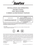
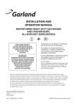
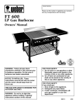
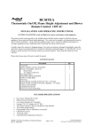
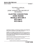
Service Manual
Master Gas
Production Griddles
models
CG-24, CG-36,
CG-48, CG-60, CG-72
FOR YOUR SAFETY:
DO NOT STORE OR USE GASOLINE
OR OTHER FLAMMABLE VAPORS OR
LIQUIDS IN THE VICINITY OF
THIS OR ANY OTHER
APPLIANCE
WARNING:
IMPROPER INSTALLATION, ADJUSTMENT,
ALTERATION, SERVICE OR MAINTENANCE
CAN CAUSE PROPERTY DAMAGE, INJURY,
OR DEATH. READ THE INSTALLATION,
OPERATING AND MAINTENANCE
INSTRUCTIONS THOROUGHLY
BEFORE INSTALLING OR
SERVICING THIS EQUIPMENT
PLEASE READ ALL SECTIONS OF THIS MANUAL
AND RETAIN FOR FUTURE REFERENCE.
THIS PRODUCT HAS BEEN CERTIFIED AS
COMMERCIAL COOKING EQUIPMENT AND
MUST BE INSTALLED BY PROFESSIONAL
PERSONNEL AS SPECIFIED.
IN THE COMMONWEALTH OF MASSACHUSETTS
THIS PRODUCT MUST BE INSTALLED BY A
LICENSED PLUMBER OR GAS FITTER. APPROVAL
NUMBER: G-1-07-05-28
For Your Safety:
Post in a prominent location, instructions to be
followed in the event the user smells gas. This
information shall be obtained by consulting
your local gas supplier.
Users are cautioned that maintenance and repairs must be performed by a Garland authorized service agent
using genuine Garland replacement parts. Garland will have no obligation with respect to any product that has been
improperly installed, adjusted, operated or not maintained in accordance with national and local codes or installation
instructions provided with the product, or any product that has its serial number defaced, obliterated or removed,
or which has been modified or repaired using unauthorized parts or by unauthorized service agents.
For a list of authorized service agents, please refer to the Garland web site at http://www.garland-group.com.
The information contained herein, (including design and parts specifications), may be superseded and is subject
to change without notice.
Garland Commercial Ranges, Ltd.
1177 Kamato Road
Mississauga, Ontario L4W 1X4 Canada
P: 905 624 0260 F: 905 624 5669
www.Garland-Group.com
Parts & Service
1 800 427 6668 (Phone, US & Canada)
1 800 361 7745 (Fax, US & Canada)
G_GC_SM_CHAINGRIDDLE_GCGTRAINING06 (03/19/13)
(03/19/13)
G_GC_SM_CHAINGRIDDLE_GCGTRAINING06
© 2013 Garland Commercial Ranges,
Ltd.1
Page
IMPORTANT INFORMATION
WARNING:
This product contains chemicals known to the state of California to cause cancer and/or birth defects
or other reproductive harm. Installation and servicing of this product could expose you to airborne
particles of glass wool/ceramic fibers. Inhalation of airborne particles of glass wool/ceramic fibers
is known to the state of California to cause cancer. Operation of this product could expose you to
carbon monoxide if not adjusted properly. Inhalation of carbon monoxide is known to the state of
California to cause birth defects or other reproductive harm.
Keep appliance area free and clear of combustibles.
Page 2
G_GC_SM_CHAINGRIDDLE_GCGTRAINING06 (03/19/13)
TABLE OF CONTENTS
IMPORTANT INFORMATION. . . . . . . . . . . . . . . . . . . . . . . . . . . . . . . . . . . . . . . . . . 2
DIMENSIONS AND SPECIFICATIONS . . . . . . . . . . . . . . . . . . . . . . . . . . . . . . . . . . 4
WHAT IS A CHAIN GRIDDLE . . . . . . . . . . . . . . . . . . . . . . . . . . . . . . . . . . . . . . . . . . 5
How Does it work? . . . . . . . . . . . . . . . . . . . . . . . . . . . . . . . . . . . . . . . . . . . . . . . . . . . . . . . . . . . . . . .5
INSTALLATION . . . . . . . . . . . . . . . . . . . . . . . . . . . . . . . . . . . . . . . . . . . . . . . . . . . . . . 6
Mechanical . . . . . . . . . . . . . . . . . . . . . . . . . . . . . . . . . . . . . . . . . . . . . . . . . . . . . . . . . . . . . . . . . . . . . .6
Gas Supply . . . . . . . . . . . . . . . . . . . . . . . . . . . . . . . . . . . . . . . . . . . . . . . . . . . . . . . . . . . . . . . . . . . . . .6
Electrical Power, Lighting & Control . . . . . . . . . . . . . . . . . . . . . . . . . . . . . . . . . . . . . . . . . . . . . . .7
Ventilation . . . . . . . . . . . . . . . . . . . . . . . . . . . . . . . . . . . . . . . . . . . . . . . . . . . . . . . . . . . . . . . . . . . . . . .7
Start-Up . . . . . . . . . . . . . . . . . . . . . . . . . . . . . . . . . . . . . . . . . . . . . . . . . . . . . . . . . . . . . . . . . . . . . . . . .7
OPERATION & MAINTENANCE. . . . . . . . . . . . . . . . . . . . . . . . . . . . . . . . . . . . . . . . 8
Cleaning. . . . . . . . . . . . . . . . . . . . . . . . . . . . . . . . . . . . . . . . . . . . . . . . . . . . . . . . . . . . . . . . . . . . . . . . .8
SERVICING. . . . . . . . . . . . . . . . . . . . . . . . . . . . . . . . . . . . . . . . . . . . . . . . . . . . . . . . . . 9
Have The Right Tools And Instruments . . . . . . . . . . . . . . . . . . . . . . . . . . . . . . . . . . . . . . . . . . . .9
Adjustments . . . . . . . . . . . . . . . . . . . . . . . . . . . . . . . . . . . . . . . . . . . . . . . . . . . . . . . . . . . . . . . . . . . . .9
Pilot Flame Adjustment . . . . . . . . . . . . . . . . . . . . . . . . . . . . . . . . . . . . . . . . . . . . . . . . . . . . . . . . . .9
Burner Air . . . . . . . . . . . . . . . . . . . . . . . . . . . . . . . . . . . . . . . . . . . . . . . . . . . . . . . . . . . . . . . . . . . . . . .9
Removing the Griddle Plate . . . . . . . . . . . . . . . . . . . . . . . . . . . . . . . . . . . . . . . . . . . . . . . . . . . . . .9
Thermostat . . . . . . . . . . . . . . . . . . . . . . . . . . . . . . . . . . . . . . . . . . . . . . . . . . . . . . . . . . . . . . . . . . . . .10
Thermocouple . . . . . . . . . . . . . . . . . . . . . . . . . . . . . . . . . . . . . . . . . . . . . . . . . . . . . . . . . . . . . . . . . .10
How To Replace A Thermocouple . . . . . . . . . . . . . . . . . . . . . . . . . . . . . . . . . . . . . . . . . . . . . . . .10
Incandescent Lamps . . . . . . . . . . . . . . . . . . . . . . . . . . . . . . . . . . . . . . . . . . . . . . . . . . . . . . . . . . . . 11
Pilot Ignition Control (Control Module) . . . . . . . . . . . . . . . . . . . . . . . . . . . . . . . . . . . . . . . . . . . 11
Gas Valve Regulator . . . . . . . . . . . . . . . . . . . . . . . . . . . . . . . . . . . . . . . . . . . . . . . . . . . . . . . . . . . . .12
Power Switches . . . . . . . . . . . . . . . . . . . . . . . . . . . . . . . . . . . . . . . . . . . . . . . . . . . . . . . . . . . . . . . . .12
Control Circuit . . . . . . . . . . . . . . . . . . . . . . . . . . . . . . . . . . . . . . . . . . . . . . . . . . . . . . . . . . . . . . . . . .12
CONTROL PANEL SCHEMATIC DIAGRAM . . . . . . . . . . . . . . . . . . . . . . . . . . . . . 13
SERVICE BULLETIN #95-5 . . . . . . . . . . . . . . . . . . . . . . . . . . . . . . . . . . . . . . . . . . . 14
Revision History (CG Griddles) . . . . . . . . . . . . . . . . . . . . . . . . . . . . . . . . . . . . . . 18
G_GC_SM_CHAINGRIDDLE_GCGTRAINING06 (03/19/13)
Page 3
DIMENSIONS AND SPECIFICATIONS
Combustible Wall Clearances
Electrical Requirements
Sides: 6” (152mm)
Manifold Pressure Required
After Built-in Regulator
Back: 6” (152mm)
Natural:
3.5" W.C. (8.75mbar)
120 V, Single Phase, 60Hz, 1 A
6’ (1829mm) power supply cord provided.
IMPORTANT:
Minimum Supply Pressure Required:
Specifications:
Propane:
10" W.C. (25mbar)
NOTE: No cord and plug on export units
Unit must be
installed on legs for proper air
circulation.
Natural:
7" W.C. (17.4mbar)
Propane:
11" W.C. (27.4mbar)
Export Voltages:
Ventilation
NOTE
Commercial cooking equipment
requires an adequate ventilation
system.
Gas Input Ratings shown are for
installations up to 2,000 feet (610mm)
above sea level.
BTU input ratings must be derated for
high altitude installations.
Refer to the National Fire
Protection Association’s standard
NFPA96.
Direct connection on junction box.
NOTE: Export voltages are available on
request.
220-240 V, 50 Hz, 0.4 A, Single Phase.
0.625
16
5.75
146
3" [76mm] Extended Bumper
to Prevent Flue Vent Blockage
2.5
84
Cooking Surface
Electric Cord/Connection
Gas Connection Rear
Gas Inlet
10
254
3.25
83
Grease Trough
Gas Connection Centered
On Unit Width [Left to Right]
20
508
35
889
24
38.75 610
984
Electric
Cord/Connection
Inches
mm
DIMENSIONS:
Available in 24, 36, 48, 60 & 72 Widths
610, 914, 1219, 1524 & 1829
5.5
140
4.75
121
15
381 Optional
Stand
Counter
Removable
Leg
Grease
Drawer 27
686
15.75
400
6
Counter 152
Finished
10 Floor
254
6
152
SIDE VIEW
1.5
38
5
127
PLAN VIEW [Model CG-48R]
Dimensions - All Models
INPUT CHART - Natural Or Propane Gas
Grease Drawer(s)
2' & 3' Units - One
4', 5' & 6' Units - Two
Finished Floor
Optional Stand
Shipping
Weight
Model
Number
BTU/
hour
kW
Gas
Inlet
CG-24R
60,000
17.60
3/4"
335/152
CG-36R
90,000
26.40
3/4"
485/220
CG-48R
120,000
35.00
3/4"
625/284
CG-60R
150,000
44.00
3/4"
765/348
CG-72R
180,000
52.70
1"
995/411
lb./kg.
FRONT VIEW [Model CG-48R]
Page 4
G_GC_SM_CHAINGRIDDLE_GCGTRAINING06 (03/19/13)
WHAT IS A CHAIN GRIDDLE
Commercial chain restaurants impose strict food procedures
on franchise owners and operators to guarantee the quality
and consistency of the product. Beef burgers, hamburgers,
french fries, onion rings, fried chicken and tortillas for
example, must meet rigid standards of quality involving the
ingredients used, the recipes followed, storage and, not least,
the cooking temperature and time of cooking.
Figure 1 -Front view of counter-top chain griddle
Accuracy of temperature control and the heating stability of
the cooking surface are essential in maintaining consistent
quality in the product. Control and stability are the two
primary features in the new chain griddle. As compared with
previous gas griddles of the same kind, temperature control
of heating zones in the chain griddle is far tighter and more
precise.
Main power
ON
green
indicator
light
Two features provide precision control. One feature is a
burner for every foot of griddle surface. The other is that each
burner is electronically monitored for temperature control.
As a result, at 30,000 BTU using natural gas, there is excellent
energy management and power recovery.
How Does it work?
Temperature sensors are embedded in the griddle plate.
Each sensor is close to the plate surface where the load
is. The effect of this arrangement is to achieve an even
temperature gradient across the plate. Thanks to the
electronic monitoring feature, a much faster response to
changes in surface temperature is achievable in the chain
griddle than in previous units.
The smoother temperature gradient per unit surface area
and accurate temperature control has made the chain
griddle an instant success. This simple explanation of the two
main features of the unit is what makes it so special. Without
fast response and a smooth gradient, the chain griddle
would be just another design among many.
Explaining why the unit is special is one thing and
understanding how it works in another. Service technicians
need to know this to have complete confidence when
servicing the unit. We describe how it works in the next part
of this section.
G_GC_SM_CHAINGRIDDLE_GCGTRAINING06 (03/19/13)
Burner ON amber
indicator light
Air vents
Flame
Securing
Pilot ON green viewport
fasteners
indicator light
for removable
Removable top
Zone
top
access panel
thermostat
access panel
Main power
switch
Hinged
drop-down
bottom half
access
panel
Zone power
Leg of counter-top
switch
style griddle
Grease tray
When the main power switch is turned on, the power
indicating lamp is illuminated and power is applied to the
thermostat input of the ignition modules. This will initiate
the pilot ignition sequence. The ignition module supplies a
spark ignition at the pilot burner and will energize the pilot
solenoid valve for a maximum trail period of 50 seconds.
If the pilot flame ignites and is sensed within the 50 second
period, the main burner output of the ignition module will
be energized. The pilot indicating lamp will illuminate. The
main burner solenoid valves are then controlled by the
thermostats. As a thermostat calls for heat, it will energize
its output and the main burner valve along with the burner
indicating lamp will energize. The main burner will cycle with
the thermostat.
There is only one trial for ignition. If the pilot flame is not
sensed during the trail period, the ignition module will lock
out. All ignition module outputs will be de-energized. To reset
the ignition module the main power switch must be turned
off for a period of 30 seconds.
Page 5
WHAT IS A CHAIN GRIDDLE continued
During normal operation, the pilot flame is continually
monitored. The flame current signal must maintain 0.15
microamps minimum. Flame failure response time is 0.8
seconds maximum. If at any time the ignition module does
not detect a pilot flame, it will repeat the ignition process by
allowing a 50 second trial of ignition.
Figure 2 – Sequence of Operation
Power
Spark
o/p
Ignition
Flame
sensor
Pilot valve
Figure 2 illustrates this sequence of operation.
Main valve
INSTALLATION
The instructions given for installation form part of the
delivery package. Anyone installing a chain griddle should
follow a strict procedure to make sure installation and
commission are safe, efficient and complies with the
applicable local codes. Here is a check list of things to do in
the order we recommend.
CAUTION : Check the pipe capacity tables given in the
installation code. When a long supply pipe run is necessary,
you may have to install a supply line lager than 3/4”
•
Have a qualified gas technician check the gas supply to
make sure it will deliver the BTUs of gas the unit requires
to operate with no more than 1/2” water pressure
drop. Also when making this check be certain that all
equipment on the gas line is turned to the ON position.
•
If you are installing the unit using a new gas installation,
make sure the supply lines have been cleaned and
purged of piping compound, chips and other debris.
Mechanical
•
•
Uncrate and check for shipping damage both obvious
and hidden. Write a damage report and report
immediately to the carrier.
Check the serial plate behind the front panel. To do this,
remove the front panel by unscrewing the two screws in
the upper right and left corners. Next unscrew the two
fasteners securing the hinged lower font panel in place.
Note the burner inputs shown on the serial number
plate. It may be necessary to refer to these later. You also
need to be certain of the type of gas to which the unit
is connected. The serial plate also specifies the type of
gas required for the unit. Also, check that the electrical
connections are in good order.
NOTE : The chain griddle is certified for installation on a
combustible base with minimum clearance of 6” (152mm)
back and 6” (152mm) sides from combustible walls.
•
Every unit is fitted with a readily accessible shut-off valve
at the main manifold. Use a minimum of 3/4” NPT pipe to
connect the incoming gas supply.
Page 6
WARNING : Use soap solution if you have to check the gas
lines for leaks.
•
Place and install the unit on the legs or caters provided,
and make sure there is a minimum of 4” (102mm) air
space below the unit for adequate air flow to the burners.
CAUTION: Check for obstructions or objects that could
restrict the air flow to the burners.
•
Using a spirit level variously across the front, rear and sides
of the unit, level it by adjusting the leveling legs.
Gas Supply
NOTE : For efficient operation, the griddle plate must be
level.
G_GC_SM_CHAINGRIDDLE_GCGTRAINING06 (03/19/13)
INSTALLATION continued
•
•
•
Each thermostat controls one zone burner though a
dual solenoid-pressure regulator valve complete with a
pressure test spigot. Check the manifold gas pressure on
each combination valve to make sure it is the same as
that shown on the serial plate. The gas pressure should be
3.5” WC for natural gas and 10.0” for propane gas.
For access to the pressure test spigots, turn the main
power switch and all zone power switches to the OFF
position and lower the front panel on its hinge. This is a
safety precaution. The test spigots are at the rear of the rear
of the combination regulator valves.
Connect your manometer to the first valve for test and
turn the manual shut-off valve to the ON position.
NOTE : The shut off valve is under the unit. When it is ON and
in the open position, the valve position is in line with the
piping. Also, see the electrical procedure below for notes on
the status indictor lights and setting the thermostats.
•
Turn the main power switch and the zone power switches
to the ON position.
•
Set all the thermostat dials to 350˚F. When all the burners
are operating, check and record the manometer reading,
which should be the same manifold pressure as that
specified on the serial plate (3.5” WC for natural gas and
10.0” for propane gas). Adjust the regulator to obtain the
pressure rate specified.
•
When satisfied with the reading obtained, turn the main
power switch OFF. Remove the manometer test tube and
re-cap the test spigot.
•
Repeat this operation on each combination regulator
valve to correctly set it. Then turn each thermostat, zone
and main power switch OFF.
Electrical Power, Lighting & Control
WARNING : Do not work on ungrounded equipment. It is
dangerous.
•
National and local electrical codes require that all devices
of this type be electrically grounded. Check to make sure
the unit is grounded.
CAUTION : Make sure the electrical connections enclosed by
the panels are in good order and undamaged before closing
and securing the front panels.
•
To check the unit lighting, turn the main power switch of
the unit to the ON position. The green light of the power
switch and the green indictor of the gas pilot of each
section of the griddle should illuminate.
CAUTION : If after two minutes the pilot ignition fails, turn
the main power switch OFF. Wait five minutes and switch the
main power ON again.
•
When the green indicator for each zone is illuminated,
turn the zone power switch for each zone ON. The
thermostats can now be set to the desired temperature.
•
The amber light burner indicator cycles with the
operation of the thermostat.
Ventilation
For efficient operation this unit requires a minimum
ventilation air supply of 50frm. The ideal method of
ventilation is a well-designed canopy of hood that exceeds 6”
(152mm) beyond all sides of the unit. Ideally, the bottom of
the hood should be set 6’6” (1981mm) from the floor.
Gas burners and pilot devices need a sufficient air supply to
operate efficiently, so do not place large objects anywhere
near them to restrict or in any way limit the air flow.
In most operations, the chain griddle will be used in
conjunction with other kitchen equipment. The need for
the ingress of air to the kitchen area must be sufficient to
compensate for the air the ventilation system abstracts.
Unless the air flow is sufficient a subnormal, and probable
negative, atmospheric pressure will result, which will
adversely affect the operation of the equipment and make
work in the kitchen area unpleasant.
Start-Up
When the chain griddle is used for the first time, the griddle
top requires seasoning. To season a griddle surface, follow
this procedure.
1. Wash the griddle surface with a hot, mild detergent or
soap solution, then rinse and dry thoroughly.
2. Set the thermostat to 175˚F for 30 minutes, then apply a
film of cooking oil to the cooking surface and wipe away
the excess.
3. After (5) five minutes, wipe the griddle plate clean.
NOTE : This griddle is equipped with a 3-pronged plug cord
set to fit any 120V AC3-prong, 15 amp-rated, grounded
receptacle.
G_GC_SM_CHAINGRIDDLE_GCGTRAINING06 (03/19/13)
Page 7
INSTALLATION continued
4. Re-set the thermostat to 275°F and apply a second film of
oil. After (5) five minutes, wipe off the excess oil.
5. Reset the thermostat to the cooking temperature and
apply a final film of oil. After (3) minutes, wipe off the
excess oil. The griddle is now seasoned and ready for use.
NOTE : We recommend reseasoning the griddle before each
day’s operations begin. Franchise operators who follow
explicit operating procedures should be made aware of this
recommendation.
OPERATION & MAINTENANCE
During idle periods, reduce the thermostat settings to
conserve energy. A setting of 175°F to 200˚F is enough to
keep the plate warm. Reducing the temperature also reduces
the load on the thermostat.
1. At then end of the operations, turn the power and zone
switches OFF. There is no need to change the thermostat
settings when the unit is not in use.
2. Don’t overheat the griddle. Excessive heat causes grease
to carbonize and makes the surfaces hard to clean.
3. For a more thorough cleaning, use Garland Ranges F69
fryer and griddle cleaner. Polish the plate to a bright finish,
then wash, rinse and thoroughly dry it.
4. Follow the procedure specified (see Start-Up) to reseason
the cooking surface.
5. To clean the exterior surface of a chain griddle, clean the
stainless steel with a hot detergent or soap solution.
Remove baked on grease by applying the cleanser in
the direction of the polishing lines of the stainless steel
surface.
3. Empty the grease trays often to avoid spillovers.
4. For extended shutdown or major maintenance, turn the
power and zone switches OFF, close the manual shut-off
gas valve, and unplug the electrical power cord.
Cleaning
1. At the end of the cooking operations, wipe and clean the
unit while it is still warm. Use a spatula to remove food
residue and burnt grease.
2. When the plate is cool, wash it with a mild detergent, dry
it, and wipe it with a slightly oiled cloth.
Page 8
CAUTION : Do not rub stainless steel in a circular motion. This
destroys the finished surface of the metal and detracts from
its appearance.
If it is necessary to remove hard and burnt on deposits
from high quality surfaces, use SCOTCH-BRITE or STAINLESS
scouring pads by running with the grain of the finished
steel. Remove heat tint the same way, using if necessary a
non-abrasive powered cleanser with the SCOTCH-BRITE or
STAINLESS pad. On no account use ordinary steel wool, it will
damage the finished surface.
G_GC_SM_CHAINGRIDDLE_GCGTRAINING06 (03/19/13)
SERVICING
Many factors affect the serviceability of equipment. In the
chain griddle, there are more components to service than in
older models. The new griddle is a compact design. Access
to the temperature control circuitry and ignition units is
easy. Service techniques for the thermocouple will vary
depending on the model type.
They unit is available with a 6” (152mm) leg which means
that under the griddle plate there is only 6” (152mm) of
working room. To replace a thermocouple it is difficult to
lift the griddle plate, firmly secured to the support frame. To
replace a thermocouple requires bottom access because the
plate is securely fixed (see Figure 3).
With this introduction to serviceability, and apart from
the features that make the chain griddle superior to more
conventional units, many of the servicing tasks are standard;
the adjustments likewise. The procedures that follow are
a plain guide to servicing, beginning with adjustments to
various components.
Have The Right Tools And Instruments
In addition to a service technician’s normal hand tools, for
servicing this chain griddle we recommend:
1. A manometer or other suitable instrument for measuring
gas pressure
2. A multimeter
3. A digital read-out temperature meter
4 A micro-ammeter
CAUTION : In this chain griddle we use a J-type
thermocouple, which requires a meter with a J-type
connection for checking. Most meters have K-type
connections.
1. To remove the upper front and lower front panels, refer to
the installation procedure given earlier.
2. To reduce the volume of gas feed to the pilot, turn the
small screw in the pilot adjusting valve clockwise.
3. To increase the gas feed to the pilot, turn the same screw
counter-clockwise.
NOTE : Adjust the gas feed to produce a 7/16” (11mm) long
flame to make sure the flame envelopes the top of the flame
sensor.
Burner Air
Make sure a burner is warm before adjusting the air shutters
and follow this procedure.
1. First, loosen the screw along the side of the burner near
the orifice.
2. A burner flame that gets too much air appears to lift
above the burner as though separated from it. This
means the shutter needs throttling back to a more closed
position.
3. A yellow tip on the flame is a sign that the shutter is
not passing enough air to feed the flame. In this case, it
necessary to open the shutter.
4. When the shutter adjustment is complete, tighten the
screw to lock the shutter setting in the adjusted position.
5. Re-close the upper and lower front panels and replace
the fasteners.
Removing the Griddle Plate
If it is necessary to remove the griddle top, follow this
procedure:
Adjustments
1. Disconnect the power supply.
Every griddle is inspected and tested before it leaves the
factory. Adjustments to the unit during installation and
servicing are the responsibility of the field operator and are
not considered to be defects in material or workmanship.
For this reason, adjustments are not covered under the
equipment warranty.
2. Remove the upper control panel.
Pilot Flame Adjustment
5. Remove the griddle top retaining bolts (both left and
right).
A pilot adjustment valve is in the line form each pilot
combination valve and access to it is behind the lower front
panel.
G_GC_SM_CHAINGRIDDLE_GCGTRAINING06 (03/19/13)
3. Open the lower control panel.
4. Disconnect all thermocouple sensors and shield bayonet
adapters. (To reassemble, see the Thermocouple section.)
6. Remove the back flue.
7. The griddle top is now easily removed.
Page 9
SERVICING continued
Thermostat
Make sure the thermostat knob is correctly aligned with
the dial indicator. To align the knob with the graduated dial
correctly, follow this procedure.
1. Turn the knob and shaft fully counter-clockwise. Loosen
the set screw in the knob and align the pointer with the
first line of the scale at the lower left position.
NOTE : When the knob is fully rotated clockwise, the pointer
should align with the last line of the scale.
2. Set the dial to 350˚F. Wait at least three cycles before
monitoring the temperature.
3. Use a surface temperature probe disc positioned on the
center line with the thermostat knob and centered front
to back on the griddle plate.
The thermostat will overshoot and undershoot as caused
by the lag time in the thermal response of the heat sourceto-plate and plate-to-sensor. The calibration temperature
will be the mid-point between the minimum and maximum
readings. Other than the alignment of the knob pointer,
there is no means to calibrate the thermostat. It has been
precisely calibrated by the manufacturer.
Thermocouple
If the temperature is incorrect check the thermocouple.
The thermocouple in this unit is a Type J, which requires
the use of a J-type temperature meter for checking. For a
complete understanding of the thermocouple used in the
chain griddle see the GCR Service Bulletin #95-5 entitled
“Thermocouples”.
A thermocouple is an accurate temperature measuring
device that consists of two dissimilar conductors joined
together at their ends. It works on a simple principle, which
is that the thermoelectric voltage between the two junctions
is proportional to the temperature difference between them.
This principle is applied to measure the temperature at one
of the junctions when the other is held at a fixed known
temperature. The technology is not new, but its use in GCR
griddles is recent.
The thermocouple probe is embedded in the griddle plate
and accurately registers the surface temperature. It is a
reliable device, but can cause problems when it fails for any
reason. In addition to deterioration from aging, it can fail in
two ways: one from an open-circuit (that is, a break in one of
its wired); the other when it short-circuits.
Page 10
If a thermocouple open circuits, the thermostat will shut off
and prevent the gas valve from opening, which means the
burner will not function.
If a unit short circuits somewhere behind the junction, it
creates a new junction and because the circuit cannot detect
the existence of a short circuit fault, there is a dramatic
increase in temperature. The thermocouple detects changes
in temperature, but because of the short circuit it may fail to
register the set temperature at the thermostat. This means
the burner may not shut off. At the other extreme, the short
circuit may occur in a place not shielded from the flue gases,
which means the burner may shut off prematurely. These are
the two conditions to look for in a shorted thermocouple.
Deterioration from aging and from welding dissimilar metals
together to for a junction introduces a contaminant that
causes mechanical stress. Over time, five to ten years, metal
fatigue from aging is certain. As a result, the temperature
curve will vary.
How To Replace A Thermocouple
A heat shield protects the thermocouple from the burner
flames and flue gases. Without the shield, the thermocouple
would register flame heat to the thermostat instead of
sensing the temperature of the griddle plate.
To replace a thermocouple (refer to Figure 3), following this
procedure:
1. Open the front panel to get access to the terminal board.
2. To withdraw the thermocouple, first remove the heat
shield. It is held in place by two combination Philip
and Robinson-heat size number 10 sheet metal screws.
Remove the heat shield by sliding it down the wire.
3. A bayonet connector secures the thermocouple in place.
Reach inside the hole and push and twist the bayonet
connector a quarter turn.
4. Remove the connection to the terminal board and feed
these wires through the heat shield. The thermocouple is
now removed.
5. Connect the wires of the replacement thermocouple, but
make sure the polarity is correct. Connect the negative
red wires to terminal 7 on the thermostat and the positive
white wire to terminal 8. (See schematic diagram).
6. Thread the thermocouple through the heat shield and
into the plate cavity.
G_GC_SM_CHAINGRIDDLE_GCGTRAINING06 (03/19/13)
SERVICING continued
Figure 3 – Replacing a thermocouple
Bayonet
adapter
Adjust to
about 4.5"
before
installing
Griddle plate
About 1"
before compression
Probe heat
shield assembly
7. The bayonet connector is spring loaded. Turn the
connector so that it makes good contact with its seat on
the plate, and adjust the spring so that at least 1” (25mm)
of spring is available to push home. This is, it is loaded 1”
(25mm) from the bayonet adapter.
8. Once this adjustment is made, remove the thermocouple
from its cavity, pry the old heat sink material from the
cavity and apply fresh heat sink compound (Garland
Commercial Ranges part #77024).
9. Re-assemble the unit.
Incandescent Lamps
These lamps, similar in construction if not in shape to
ordinary incandescent light bulbs, sometimes fail because
of metallurgical breakdown of the light filament material.
The green status light (PL1) should illuminate when the main
switch SW1 is closed.
G_GC_SM_CHAINGRIDDLE_GCGTRAINING06 (03/19/13)
•
If PL1 doesn’t illuminate when SW1 is closed, replace it.
•
Failure of the amber lights (PL3, PL4, etc.) monitoring the
zones cycle with the thermostat is not easy to detect.
When on, an amber zone light is working. If it does not
appear to light as part of the ‘burner on’ cycle, check. If
the thermostat cycles the burner to be on, the PL amber
light should illuminate.
Pilot Ignition Control (Control Module)
The Johnson G770 pilot ignition unit will lock out if the pilot
flame is not sensed before the end of the ignition trial period
and has to be reset.
•
To reset the ignition control, turn off the thermostat for a
minimum of 30 seconds.
Page 11
SERVICING continued
Gas Valve Regulator
Power Switches
The gas valve regulator (See fig 4) used on the griddle is
AGA and CGA approved. The direction of gas flow is at
right angles, right and left viewing the inlet. For setting the
regulator:
Dust caps fitted on the main power switch and zone
switches protect them from dust and the corrosive effect of
cooking fumes. If the dust caps are removed, or not replaced
following servicing, the switches will deteriorate and have
reduced life expectancy. Replace the dust caps following
servicing.
•
•
For natural gas, Part #240510 regulator, set at 3.5” W.C. at
22 CFH air each side at 7” W.C. inlet pressure. Regulator
adjustment range is 2.8” to 4.0” WC.
From propane, part # 245101 regulator, set at 10.0” W.C.
Figure 4 – Gas Valve Regulator
Flow
Control Circuit
Figure 4 shows the control schematic for the GC-48 unit,
which has two zones. The ignition and temperature controls
for each zone are identical.
Flow
Pressure
setting screw
Turn counter-clockwise
to increas the pressure
setting
Turn clockwise to
decrease the pressure
Inlet
Page 12
G_GC_SM_CHAINGRIDDLE_GCGTRAINING06 (03/19/13)
CONTROL PANEL SCHEMATIC DIAGRAM
Figure 4 – Control schematic for a Model CG-48
Chain Griddle
G_GC_SM_CHAINGRIDDLE_GCGTRAINING06 (03/19/13)
Page 13
SERVICE BULLETIN #95-5
FROM – National Service Department
TO – National Service Binder Holders
Subject:
BULLETIN NO. #95-5
DATE – February 24, 1995
Subject: Thermocouples used in the Chain Griddle
Models CG-36, CG-48, CG-60 & CG-72
This bulletin supplements the chain Griddle Service Manual with a description of the basics of
thermocouple theory and how to use the degree/millivolt tables issued as part of this bulletin.
This bulletin deals with the thermocouple only and how it registers temperature changes.
The type J thermocouple on the new Chain Griddle measures the plate temperature within a
range of accuracy of 2˚F to 4˚F. The J designation refers to the conductors used and, therefore, the
thermoelectric characteristics of the conductors that form the thermocouple. In the Type J unit,
the conductors are iron and the alloy constantan. Constantan is an alloy of copper and nickel.
Thermocouple technology for sensing temperature has been in use for a long time but the Type J
thermocouple is new to Garland Commercial Ranges Limited applications.
To dissimilar metals joined together, as in Figure 1, cause a thermoelectric current to flow in the
circuit formed when the junctions are at different temperatures. The current will continue to
flow as along as the junctions (T1 and T2) remain at different temperatures. Thermoelectricity
is the direct conversion of heat into electricity and vice versa. The electric motive force (emf )
producing the current is called the “Seebeck Thermal Emf” (Seebeck after the discoverer), and is
proportional to the temperature difference between the two junctions.
Three laws govern the way thermocouples work: the law of homogeneous circuits, the law of
intermediate metals and the law of successive or intermediate temperatures. The first law is that
a thermocouple circuit must use different metals; the second is that a third metal introduced
will not affect the couple provided it is maintained at the same temperature along its entire
length; the third provides a means of relating the emf generated to a standardized constant
temperature. Refer to a textbook about thermocouples for a fuller explanation of these laws.
Metal A
I
T1 junction
T2 junction
V
Metal B
Metal B
Figure 1
T = Temperature
I = Current
V = Voltage (emf )
If the cold junction is at a known or reference temperature it is a simple matter to compare this
with the hot junction at the probe of the thermocouple to obtain an accurate measure of the
hot junction temperature. In practice, the cold junction is eliminated by the use of electrical or
hardware compensating methods.
Page 14
G_GC_SM_CHAINGRIDDLE_GCGTRAINING06 (03/19/13)
SERVICE BULLETIN #95-5 continued
Tables of millivolt values for degrees Fahrenheit (at reference junction temperature 32˚) and
Centigrade (at reference junction temperature 0˚) have been written and extracts from these
tables form part of this bulletin. These are required if service technicians need to check a
thermocouple without a J calibrated temperature meter.
Check the thermocouple if you find the temperature variation of the thermostat is more than ±
5˚F from the set point. To check a thermocouple, follow this procedure:
Note: The Type J thermocouple requires the use of a Type J temperature meter.
If a type J meter is not available use a millivolt meter and refer to the tables of
degrees/millvolt values following, to calculate the cold junction compensation.
Remember that the accuracy of you measurements can be no more accurate than your
instruments. Thermocouples generate very small voltages. Many voltmeters cannot read
millivoltages accurately.
Set all control thermostats to the same temperature (350˚F). Allow the griddle plate to saturate
and achieve a steady temperature.
Place a surface temperature probe on the griddle surface about the thermocouple you want to
check. The surface must be cleaned before this procedure. If there is any grease residue on the
probe or griddle plate, it will introduce an error in your reading.
Take the temperature reading of the plate above the controlling thermocouple.
Disconnect the thermocouple from the temperature and, either connect it to a J type calibrated
temperature meter to measure the temperature output directly or, do the following: measure
and record the millivolts generated by the thermocouple. Measure the ambient temperature.
Refer to the table and add the corresponding millvoltage for the ambient temperature to the
value measured from the thermocouple. Find the corresponding temperature in the chart for
millvoltge result.
Example: if the ambient room temperature is 20˚ C add the millvolt value of
20˚C (1.019mV) from the chart to the millvolt reading of the meter and find the
temperature value in the chart. The temperature should match the reading on
the surface of the plate.
G_GC_SM_CHAINGRIDDLE_GCGTRAINING06 (03/19/13)
Page 15
SERVICE BULLETIN #95-5 continued
Type J - Thermocouples (0° to 440°F)
EMF In Millivolts - Reference Junction 0°F
°F
0
10
20
30
40
50
60
70
80
90
100
110
120
130
140
150
160
170
180
190
200
210
220
230
240
250
260
270
280
290
300
310
320
330
340
350
360
370
380
390
400
410
420
430
440
450
Page 16
0
-0.885
-0.611
-0.334
-0.058
0.224
0.507
0.791
1.076
1.363
1.652
1.942
2.233
2.526
2.820
3.115
3.411
3.708
4.006
4.305
4.605
4.906
5.207
5.509
5.812
6.116
6.420
6.724
7.029
7.335
7.641
7.947
8.253
8.560
8.867
9.175
9.483
9.790
10.098
10.407
10.715
11.023
11.332
11.640
11.949
12.257
12.566
1
-0.868
-0.583
-0.307
-0.028
0.253
0.535
0.891
1.105
1.392
1.681
1.971
2.263
2.555
2.849
3.145
3.441
3.738
4.036
4.335
4.635
4.936
5.238
5.540
5.843
6.146
6.450
6.755
7.060
7.365
7.671
7.977
8.284
8.591
8.898
9.206
9.513
9.821
10.129
10.437
10.746
11.054
11.363
11.671
11.980
12.288
12.597
2
-0.831
-0.556
-0.279
0.000
0.281
0.563
0.848
1.134
1.421
1.710
2.000
2.292
2.585
2.879
3.174
3.470
3.768
4.066
4.365
4.665
4.966
5.268
5.570
5.873
6.176
6.481
6.785
7.090
7.396
7.702
8.008
8.315
8.622
8.929
9.236
9.544
9.852
10.160
10.468
10.777
11.085
11.292
11.702
12.010
12.319
12.627
3
-0.803
-0.528
-0.251
0.028
0.309
0.592
0.876
1.262
1.450
1.739
2.029
2.321
2.614
2.908
3.204
3.500
3.798
4.096
4.395
4.695
4.996
5.298
5.600
5.903
6.207
6.511
6.816
7.121
7.426
7.732
8.039
8.345
8.652
8.960
9.267
9.575
9.883
10.191
10.499
10.807
11.116
11.424
11.733
12.041
12.350
12.658
4
-0.776
-0.501
-0.223
0.056
0.337
0.620
0.905
1.191
1.479
1.768
2.058
2.350
2.644
2.938
3.233
3.530
3.827
4.126
4.425
4.725
5.026
5.328
5.630
5.934
6.237
6.541
6.846
7.151
7.457
7.763
8.069
8.376
8.683
8.990
9.298
9.606
9.914
10.222
10.530
10.838
11.147
11.455
11.764
12.072
12.381
12.689
5
-0.748
-0.473
-0.195
0.084
0.365
0.648
0.933
1.220
1.507
1.797
2.088
2.380
2.673
2.967
3.263
3.560
3.857
4.156
4.455
4.755
5.057
5.358
5.661
5.964
6.268
6.572
6.877
7.182
7.488
7.794
8.100
8.407
8.714
9.021
9.329
9.636
9.994
10.252
10.561
10.869
11.177
11.486
11.794
12.103
12.411
12.820
6
-0.721
-0.445
-0.168
0.112
0.394
0.677
0.962
1.248
1.536
1.826
2.117
2.409
2.702
2.997
3.293
3.589
3.887
4.186
4.485
4.786
5.087
5.389
5.691
5.994
6.298
6.602
6.907
7.212
7.518
7.824
8.131
8.437
8.745
9.052
9.359
9.667
9.975
10.283
10.592
10.900
11.208
11.517
11.825
12.134
12.442
12.751
7
-0.694
-0.418
-0.140
0.140
0.422
0.705
0.990
1.277
1.565
1.855
2.146
2.438
2.732
3.026
3.323
3.619
3.917
4.216
4.515
4.816
5.117
5.419
5.721
6.025
6.328
6.633
6.938
7.243
7.549
7.855
8.161
8.468
8.775
9.083
9.390
9.698
10.006
10.314
10.622
10.931
11.239
11.548
11.856
12.165
12.473
12.782
8
-0.666
-0.390
-0.112
0.168
0.450
0.734
1.019
1.396
1.594
1.884
2.175
2.467
2.761
3.056
3.352
3.649
3.947
4.245
4.545
4.846
5.147
5.449
5.752
6.055
6.359
6.663
6.968
7.274
7.579
7.885
8.192
8.499
8.806
9.113
9.421
9.729
10.037
10.345
10.653
10.962
11.270
11.578
11.887
12.196
12.504
12.813
9
-0.639
-0.362
-0.084
0.196
0.478
0.762
1.048
1.335
1.623
1.913
2.204
2.497
2.791
3.085
3.381
3.678
3.976
4.275
4.575
4.876
5.177
5.479
5.782
6.085
6.389
6.694
6.999
7.304
7.610
7.914
8.223
8.530
8.837
9.144
9.452
9.760
10.068
10.376
10.684
10.992
11.301
11.609
11.918
12.226
12.535
12.843
10
-0.611
-0.334
-0.058
0.224
0.507
0.791
1.076
1.363
1.652
1.942
2.233
2.526
2.820
3.115
3.411
3.708
4.006
4.305
4.605
4.906
5.207
5.509
5.812
6.116
6.420
6.724
7.029
7.335
7.641
7.947
8.253
8.560
8.867
9.175
9.483
9.790
10.098
10.407
10.715
11.023
11.332
11.640
11.949
12.257
12.566
12.875
G_GC_SM_CHAINGRIDDLE_GCGTRAINING06 (03/19/13)
SERVICE BULLETIN #95-5 continued
Type J - Thermocouples (0° to 240°C)
EMF In Millivolts - Reference Junction 0°C
°C
0
10
20
30
40
50
60
70
80
90
100
110
120
130
140
150
160
170
180
190
200
210
220
230
240
0
0.000
0.507
1.019
1.536
2.058
2.585
3.115
3.649
4.186
4.725
5.268
5.812
6.359
6.907
7.457
8.008
8.560
9.113
9.667
10.222
10.777
11.332
11.887
12.442
12.998
1
0.050
0.550
1.070
1.588
2.111
2.639
3.168
3.702
4.239
4.780
5.322
5.867
6.414
6.962
7.512
8.063
8.616
9.169
9.723
10.277
10.832
11.387
11.943
12.498
13.503
2
0.101
0.609
1.112
1.640
2.163
2.691
3.221
3.756
4.293
4.834
5.376
5.921
6.468
7.017
7.567
8.118
8.671
9.224
9.778
10.333
10.888
11.443
11.998
12.553
13.109
3
0.151
0.660
1.174
1.693
2.216
2.743
3.775
3.809
4.347
4.868
5.431
5.976
6.523
7.072
7.622
8.174
8.726
9.279
9.834
10.388
10.943
11.498
12.054
12.609
13.164
4
0.202
0.711
1.115
1.745
2.260
2.796
3.328
3.863
4.401
4.942
5.485
6.031
6.578
7.127
7.677
8.229
8.788
9.335
9.889
10.444
10.999
11.554
12.109
12.664
13.220
G_GC_SM_CHAINGRIDDLE_GCGTRAINING06 (03/19/13)
5
0.253
0.762
1.277
1.797
2.321
2.849
3.381
3.917
4.455
4.996
5.540
6.085
6.633
7.182
7.732
8.284
8.837
9.390
9.944
10.499
11.054
11.609
12.165
12.720
13.275
6
0.303
0.813
1.329
1.849
2.374
2.902
3.435
3.971
4.509
5.050
5.594
6.140
6.688
7.237
7.787
8.339
8.892
9.446
10.000
10.555
11.110
11.665
12.220
12.776
13.331
7
0.354
0.865
1.381
1.901
2.426
2.956
3.488
4.024
4.563
5.105
5.649
6.195
6.742
7.292
7.843
8.394
8.947
9.501
10.055
10.610
11.165
11.720
12.276
12.831
13.386
8
0.405
0.916
1.432
1.954
2.479
3.009
3.542
4.078
4.617
5.159
5.703
6.249
6.797
7.237
7.898
8.450
9.003
9.556
10.111
10.666
11.221
11.776
12.331
12.887
14.442
9
0.456
0.967
1.484
2.006
2.532
3.062
3.595
4.132
4.671
5.213
5.758
6.304
6.852
7.402
7.953
8.505
9.058
9.612
10.166
10.721
11.276
11.831
12.387
12.942
13.497
10
0.507
1.019
1.536
2.058
2.585
3.115
3.649
4.186
4.724
5.268
5.813
6.359
6.907
7.457
8.008
8.560
9.113
9.667
10.222
10.777
11.332
11.887
12.442
12.998
13.553
Page 17
Revision History (CG Griddles)
PAGE#
4
1
Page 18
SECTION
Dimensions and
Specifications
NOTES
Missing manifold pressure info. Copied from latest Spec Sheet dated 11/13/12.
Revised operating pressure data for LP, 27.4 mbar. Was 24.4 mbar.
Modified footer info.
DATE
MAR 19/13
G_GC_SM_CHAINGRIDDLE_GCGTRAINING06 (03/19/13)
G_GC_SM_CHAINGRIDDLE_GCGTRAINING06 (03/19/13)
Page 19
Master Gas Production Griddles — CG Models Service Manual
Garland Commercial Ranges, Ltd.
1177 Kamato Road
Mississauga, Ontario L4W 1X4 Canada
P: 905 624 0260 F: 905 624 5669
www.Garland-Group.com
Parts & Service
1 800 427 6668 (Phone, US & Canada)
1 800 361 7745 (Fax, US & Canada)