1
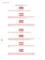
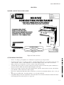
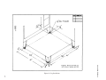
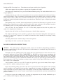
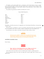
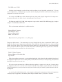
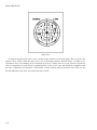
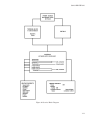
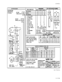
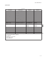
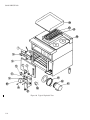
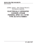
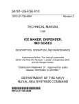
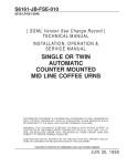
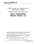
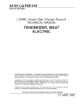
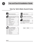
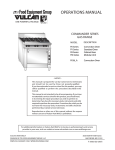
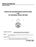
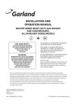
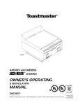
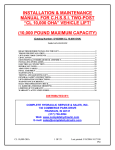
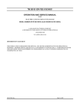
S6161-DR-FSE-010
0910-LP-105-5863
REVISION 1
TECHNICAL MANUAL
FOR
[SGML VERSION; SEE RECORD OF
REVISIONS ]
ELECTRIC CONVECTION
OVEN RANGE
MODELS RF21SM-A
RF21SM-C
RF21SM-G
DISTRIBUTION STATEMENT E: DISTRIBUTION AUTHORIZED TO DOD COMPONENTS
ONLY; CRITICAL TECHNOLOGY; (15 SEP 2006). OTHER REQUESTS SHALL BE
REFERRED TO THE NAVAL SEA SYTEMS COMMAND ((SEA-09T).)
WARNING: THIS DOCUMENT CONTAINS TECHNICAL DATA WHOSE EXPORT IS
RESTRICTED BY THE ARMS EXPORT CONTROL ACT (TITLE 22, U.S.C. SEC 2751, ET
SEQ.) OR THE EXPORT ADMINISTRATION ACT OF 1979, AS AMENDED, TITLE 50,
U.S.C., APP 2401 ET SEQ. VIOLATIONS OF THESE EXPORT LAWS ARE SUBJECT TO
SEVERE CRIMINAL PENALTIES. DISSEMINATE IN ACCORDANCE WITH PROVISIONS
OF DOD DIRECTIVE 5230.25(D).
DESTRUCTION NOTICE: DESTROY BY ANY METHOD THAT WILL PREVENT DISCLOSURE OF CONTENTS OR RECONSTRUCTION OF THIS DOCUMENT.
SUPERSEDURE NOTICE: THIS PUBLICATION SUPERSEDES S6161-DR-FSE-010
DATED 1 NOV 1986, AND ALL CHANGES THERETO.
PUBLISHED BY DIRECTION OF COMMANDER, NAVAL SEA SYSTEMS COMMAND
15 SEP 2006
TITLE-1 / (TITLE-2 Blank)@@FIpgtype@@TITLE@@!FIpgtype@@
@@FIpgtype@@TITLE@@!FIpgtype@@
TITLE-2
@@FIpgtype@@BLANK@@!FIpgtype@@
S6161-DR-FSE-010
RECORD OF REVISIONS
REVISION NO.
DATE
1
15 SEPTEMBER
2006
TITLE AND/OR BRIEF DESCRIPTION/PREPARING ACTIVITY
INCORPORATED TMDER Q90616-02-GK07. CHANGE AUTHORIZED BY NSWCCD-SSES CODES 9442 AND 9783. THE FOLLOWING WAS CHANGED: FIGURES #1, #5, AND #6. ADDED
CIRCUIT BREAKER TO PARTS LIST. MODIFIED OPERATING
INSTRUCTIONS.
NOTE
THIS TECHNICAL MANUAL (TM) HAS BEEN DEVELOPED FROM AN INTELLIGENT ELECTRONIC
SOURCE KNOWN AS STANDARD GENERALIZED MARKUP LANGUAGE (SGML). THERE IS NO LOEP.
ALL CHANGES, IF APPLICABLE, ARE INCLUDED. THE PAGINATION IN THIS TM WILL NOT MATCH
THE PAGINATION OF THE ORIGINAL PAPER TM; HOWEVER, THE CONTENT IS EXACTLY THE SAME.
ANY CHANGES RECEIVED AFTER RECEIPT OF THIS TM WILL ONLY FIT IN THIS PAGINATED VERSION.
RECORD OF REVISIONS-1 / (RECORD OF REVISIONS-2 Blank)
RECORD OF REVISIONS-2
@@FIpgtype@@BLANK@@!FIpgtype@@
S6161-DR-FSE-010
FOREWORD
This technical manual provides description, operation, maintenance, troubleshooting, repair and parts list
information for the Electric Convection Oven Range. This technical manual is intended for guidance of and use
by personnel operating and maintaining the equipment described herein.
Ships, training activities, supply points, depots, Naval Shipyards and Supervisors of Shipbuilding are
requested to arrange for the maximum practical use and evaluation of NAVSEA technical manuals. All errors,
omissions, discrepancies and suggestions for improvement to NAVSEA technical manuals shall be forwarded to:
COMMANDER,
CODE 310 TMDER, BLDG 1388
NAVSURFWARCENDIV NSDSA
4363 MISSILE WAY
PORT HUENEME CA 93043-4307
on NAVSEA/SPAWAR Technical Manual Deficiency/Evaluation Report (TMDER), NAVSEA form 4160/1. All
feedback comments shall be thoroughly investigated and originators will be advised of action resulting therefrom.
One copy of NAVSEA form 4160/1 is at the end of each separately bound technical manual 8-1/2 x 11 inches
or larger. Copies of NAVSEA form 4160/1 may be requisitioned from the Naval Systems Data Support Activity
Code 310 at the above address. Users are encouraged to transmit deficiency submittals via the Naval Systems
Data Support Activity web site located at:
http://nsdsa.phdnswc.navy.mil/tmder/tmder-generate.asp?lvl=1
Individual electronic TMs do not contain NAVSEA form 4160/1 but are linked to an electronic version on
the resident CD-ROM. Therefore, we encourage the user to transmit deficiency submittals via the Naval Systems
Data Support Activity web site located above.
FOREWORD-1 / (FOREWORD-2 Blank)
FOREWORD-2
@@FIpgtype@@BLANK@@!FIpgtype@@
S6161-DR-FSE-010
TABLE OF CONTENTS
Chapter/Paragraph
1
Page
MARINE CONVECTION OVEN RANGE . . . . . . . . . . . . . . . . . . . . . .
1-1
OUTSTANDING FEATURES. . . . . . . . . . . . . . . . . . . . . . . . . . . . . . .
1-1
ARCHITECT SPECIFICATIONS.
. . . . . . . . . . . . . . . . . . . . . . . . . . . .
1-2
INSTALLATION INSTRUCTIONS. . . . . . . . . . . . . . . . . . . . . . . . . . . .
1-2
OVEN OPERATING INSTRUCTIONS. . . . . . . . . . . . . . . . . . . . . . . . . .
1-3
RANGE TOP OPERATING INSTRUCTIONS. . . . . . . . . . . . . . . . . . . . . .
1-6
MAINTENANCE INSTRUCTIONS. . . . . . . . . . . . . . . . . . . . . . . . . . . .
1-7
SERVICE PROCEDURE. . . . . . . . . . . . . . . . . . . . . . . . . . . . . . . . . .
1-8
MAJOR COMPONENT DISASSEMBLY, REPAIR, REPLACEMENT AND
REASSEMBLY. . . . . . . . . . . . . . . . . . . . . . . . . . . . . . . . . . . . . .
1-17
PARTS LIST. . . . . . . . . . . . . . . . . . . . . . . . . . . . . . . . . . . . . . . . .
1-21
i
S6161-DR-FSE-010
LIST OF TABLES
Table
Title
Troubleshooting
ii
Page
. . . . . . . . . . . . . . . . . . . . . . . . . . . . . . . . . . . . . .
1-12
Parts List . . . . . . . . . . . . . . . . . . . . . . . . . . . . . . . . . . . . . . . . . .
1-21
S6161-DR-FSE-010
LIST OF ILLUSTRATIONS
Figure
Title
Page
#1
Picture of Oven . . . . . . . . . . . . . . . . . . . . . . . . . . . . . . . . . . . . . . .
1-1
#2
Specifications . . . . . . . . . . . . . . . . . . . . . . . . . . . . . . . . . . . . . . . .
1-4
#3
Leg Installation . . . . . . . . . . . . . . . . . . . . . . . . . . . . . . . . . . . . . . .
1-5
#4
Service Block Diagram
#5
Wiring Diagram
#6
Typical Exploded View
. . . . . . . . . . . . . . . . . . . . . . . . . . . . . . . . . .
1-11
. . . . . . . . . . . . . . . . . . . . . . . . . . . . . . . . . . . . . .
1-19
. . . . . . . . . . . . . . . . . . . . . . . . . . . . . . . . . .
1-22
iii
S6161-DR-FSE-010
SAFETY SUMMARY
GENERAL SAFETY NOTICES
The following general safety notices supplement the specific warnings and cautions appearing elsewhere
in this manual. They are recommended precautions that must be understood and applied during operation and
maintenance of the equipment covered herein. Should situations arise that are not covered in the general or specific safety precautions, the commanding officer or other authority will issue orders as deemed necessary to cover
the situation. No work shall be undertaken on energized equipment or circuits until approval of the commanding
officer is obtained, and then only in accordance with Naval Ships Technical Manual (NSTM) S9086-KC-STM010/Chapter 300.
DO NOT REPAIR OR ADJUST ALONE
Under no circumstances shall repair or adjustment of energized equipment be attempted alone. The immediate presence of someone capable of rendering first aid is required. Before making adjustments, be sure to protect against grounding. If possible, adjustments should be made with one hand, with the other hand free and clear
of equipment. Even when power has been removed from equipment circuits, dangerous potentials may still exist
due to retention of charges by capacitors. Circuits must be grounded and all capacitors discharged prior to
attempting repairs.
TEST EQUIPMENT
Make certain test equipment is in good condition. If a metal-cased test meter must be held, ground the case
of the meter before starting measurement. Do not touch live equipment or personnel working on live equipment
while holding a test meter. Some types of measuring devices should not be grounded; these devices should not
be held when taking measurements.
INTERLOCKS
Interlocks are provided for safety of personnel and equipment and should be used only for the purpose
intended. They should not be battle shorted or otherwise modified except by authorized maintenance personnel.
Do not depend solely upon interlocks for protection. Whenever possible, disconnect power at the power distribution source.
MOVING EQUIPMENT
Personnel shall remain clear of moving equipment. If equipment requires adjustment while in motion, a
safety watch shall be posted. The safety watch shall have a full view of the operations being performed, and
immediate access to controls capable of stopping equipment motion.
FIRST AID
An injury, no matter how slight, shall never go unattended. Always obtain first aid or medical attention
immediately, and file an injury report in accordance with OPNAVINST 5102.1 series, subj: Mishap Investigation
and Reporting.
iv
S6161-DR-FSE-010
SAFETY SUMMARY - Continued
RESUSCITATION
Personnel working with or near high voltage shall be familiar with approved methods of resuscitation.
Should someone be injured and stop breathing, begin resuscitation immediately. A delay could cost the victim’s
life. Resuscitation procedures shall be posted in all electrically hazardous areas.
GENERAL PRECAUTIONS
The following general precautions are to be observed at all times.
1.
Install and ground all electrical components associated with this system/ equipment in accordance
with applicable Navy regulations and approved shipboard practices.
2.
Ensure that all maintenance operations comply with Navy Occupational Safety and Health
(NAVOSH) Program Manual for Forces Afloat, OPNAVINST 5100.19 series.
3.
Observe precautions set forth in NSTM S9086-KC-STM-010/Chapter 300 with respect to electrical
equipment and circuits.
4.
Ensure that protective guards and shutdown devices are properly installed and maintained around
rotating parts of machinery and high voltage sources.
5.
Do not wear loose clothing while working around rotating parts of machinery.
6.
Ensure that special precautionary measures are employed to prevent applying power to the system/
equipment any time maintenance work is in progress.
7.
Do not make any unauthorized alterations to equipment or components.
8.
Before working on electrical system/equipment, check with voltmeter to ensure that system is not
energized.
9.
Consider all circuits not known to be ″dead,″ ″live″ and dangerous at all times.
10. When working near electricity, do not use metal rules, flashlights, metallic pencils, or any other
objects having exposed conducting material.
11. Deenergize all equipment before connecting or disconnecting meters or test leads.
12. When connecting a meter to terminals for measurement, use range higher than expected voltage.
13. Before operating equipment or performing any tests or measurements, ensure that frames of all
motors and starter panels are securely grounded.
14. Ensure that area is well-ventilated when using cleaning compound or solvent. Avoid prolonged
breathing of fumes and compound or solvent contact with skin or eyes.
WARNINGS AND CAUTIONS Specific warnings and cautions applying to the system/equipment covered by this manual are summarized below. These warnings and cautions appear elsewhere in the manual following paragraph headings and immediately preceding the text to which they apply. They are repeated here for
emphasis.
v
S6161-DR-FSE-010
SAFETY SUMMARY - Continued
WARNING
Remove the spacers and lower the top onto the oven. (Page 1-2)
WARNING
Make sure the six wire leads to supply electricity to the cook top are not
crimped between the oven and range top. (Page 1-3)
WARNING
Burns could occur when dealing with hot grease!! Empty grease drawers
daily or when they are 1/3 full. They are easily removed for washing. (Page
1-7)
WARNING
Disconnect from power before attempting any repair. (Page 1-12)
WARNING
Disconnect power before opening panels. All parts referred to are illustrated
and identified on Figure #6, Typical Exploded View. (Page 1-12)
WARNING
When testing for ″grounds″, power must be disconnected from unit. (Page
1-13)
WARNING
″Disconnect the unit from power source before testing″. Again using the
OHM-meter, check for continuity by connecting to one terminal on the block
vi
S6161-DR-FSE-010
and using the probe locate the terminal that acts as the other end of the loop.
The switches and other components in the loop must be in the ″on″ position
to satisfy continuity requirement. (Page 1-15)
WARNING
Disconnect range from power before attempting any repair. (Page 1-17)
CAUTION
Prior to putting any range or oven into full time operation at normal cooking temperatures, it must be thoroughly ″seasoned″ or dried out. Moisture
absorption in the closed spaces, in the insulation and even inside the heating
elements can cause future trouble if not properly treated. (Page 1-3)
CAUTION
All French plates should be turned to the off position when not in use.
Allowing these elements to stay in the full on or high position with nothing
on top to absorb or dissipate the heat is detrimental to element life. (Page
1-7)
CAUTION
When scraping griddle surface, do not scrape the splash guard. It may
eventually be cut through. (Page 1-8)
CAUTION
After installing the new thermostat be positive the silver tube is not near any
exposed terminals. If the thermostat tube touches any live terminals it will
be destroyed and have to be replaced again. (Page 1-17)
vii / (viii Blank)
viii
@@FIpgtype@@BLANK@@!FIpgtype@@
S6161-DR-FSE-010
CHAPTER 1
MARINE CONVECTION OVEN RANGE
Figure #1 Picture of Oven
OUTSTANDING FEATURES.
•
Choice of cooking top arrangements are combinations of grills, hot tops and speed units.
•
Each twelve inch section of cooking top shall be controlled independently by its own switch. Convection oven
controls include a 150° F - 450° F thermostat, on-off switch, damper control, and a loud one hour timer.
Range controls are located in the cool zone to ensure a long and accurate life.
A spatula wide grease gutter is located on the front of the range. Grease from the front gutter is funneled to a
large grease drawer which runs the full width and depth of the range.
Oven is large enough to hold six racks (three supplied, three optional). Oven holds six 18 inch x 26 inch bun
pans and three 12 inch x 20 inch x 4 inch food pans.
Each oven is hand packed with three inches of insulation on all sides for maximum efficiency and a cooler galley.
The range is provided with a 12 month warranty to cover all parts and labor.
Lang Marine Ranges meet the requirements of the United States Coast Guard and National Sanitation Foundation Testing Laboratory. The range is U. L. approved.
•
•
•
•
•
•
1-1
S6161-DR-FSE-010
ARCHITECT SPECIFICATIONS.
•
The Lang Convection Oven Range has the largest convection oven in the industry: 17 inch high x 20 inch wide
x 29 inch deep.
•
Standard finish shall be high quality stainless steel front, front gutter, and 6 inch front landing. Balance is grey
hammertone enamel. Available at additional cost stainless steel sides, back rear gutter, back riser and 6 inch bolt
down legs.
Ranges are furnished, as standard equipment, in two-piece construction - top and oven - to permit entrance
through narrow 26 inch galley doors.
Standard equipment includes nickle plated sea rails over the tops and speed units, stainless steel grab bar and
door latch.
Electrical switch box shall be furnished, if required or specified.
Oven interior shall be constructed of non-chipping aluminized steel.
Convection oven motors are 1/3 H.P., 1750 RPM, prelubricated for long life. Heating elements and fan are
located on the right side of the oven.
208-V, 240-V, and 480-V ovens are equipped with hydralic-magnetic circuit breakers as standard equipment.
•
•
•
•
•
•
INSTALLATION INSTRUCTIONS.
The Lang Model RF21 Convection Oven Range was designed in modular construction to allow passage
through a 26 inch by 66 inch watertight door.
Do not remove crating until the unit is as near its location as practical. This will help prevent damage normally associated with movement through door and hallways.
When the range is as close as possible to the final installation remove the crating material from the oven section. Look inside the oven cavity to locate the oven legs.
Remove the legs from inside the oven. Attach the legs to bottom corner of the oven using two each 3/8-16
X 5/8 bolts per leg. The bolts are provided and will also be found inside the oven.
Remove crating from range top.
Place spacers, (ie: 2 X 4 wood block not supplied) at the front and rear of the oven top.
Place the range top on the spacers that are located on top of the oven.
The six wire leads to supply electricity to the cook top are bundled under the front bottom of the top. Route
these wires through the bushing provided in the oven top.
Align the four locating pins in the bottom corner of the top with the four holes in each corner of the oven
top.
WARNING
Remove the spacers and lower the top onto the oven.
1-2
S6161-DR-FSE-010
WARNING
Make sure the six wire leads to supply electricity to the cook top are not
crimped between the oven and range top.
Use the wiring diagram (Figure #5) provided in this manual for determining the connections of the cook top
wires to the oven terminal block.
Electrical service connection is made through the bottom of the oven. A hole is provided for the attachment
of 1 1/4 inch conduit. See ″Top View″ of Figure #2.
Use the wiring diagram provided in this manual to determine the electrical specification.
See Figure #3 for Bolt-Down Leg Spacing and Bolt Hole Size.
OVEN OPERATING INSTRUCTIONS.
Controls and Signals Lights. The toggle switch on the lower portion of the control panel energizes the fan motor
and activates the thermostatically controlled circuit for the oven heating elements. When this switch is in the on
position, the indicator light will be illuminated.
Rotating the thermostat control knob from ″off″ position to selected temperature causes indicator light to illuminate and closes the contactor that feeds power to the heating elements. This light will cycle ″on and off″ as the
thermostat calls for heat in the oven. The blower however, operates continuously while the toggle switch is in the
″on″ position.
The black control knob operates a damper in the oven vent stack. Damper is open when knob is pulled outward.
The two fuses on the control panel protect the electrical components from overload.
Initial preheat.
CAUTION
Prior to putting any range or oven into full time operation at normal cooking temperatures, it must be thoroughly ″seasoned″ or dried out. Moisture
absorption in the closed spaces, in the insulation and even inside the heating
elements can cause future trouble if not properly treated.
To ″season″ the Lang convection oven, after making the proper electrical connection, set the thermostat dial
at 200° F and turn the toggle switch ″on″. Allow unit to cycle at least 15 minutes at this heat level. Reset the
thermostat to 250° F allowing the same time. Then reset the thermostat to 350° F. The oven should be operated
at this heat level for 5 hours, to insure the complete removal of all moisture.
1-3
S6161-DR-FSE-010
Figure #2 Specifications
1-4
1-5
S6161-DR-FSE-010
Figure #3 Leg Installation
S6161-DR-FSE-010
Loading the F6S Convection Oven.
Turn thermostat and power switch to the off position.
Adjust oven support racks to positions or spacing for the product to be baked.
Pan support racks should always be spaced for maximum uniform spacing. The word uniform in this case is
of great importance
Counting from the top of the oven, rack position 2-4-6, are used most frequently for bake items having a
relatively high profile. Using even numbered rack positions provides the uniform spacing essential to uniform
baking results. Cookies, grilled cheese sandwiches and like items can be placed on all rack positions for a full
load because of their low profile in shallow pans or on cookie sheets. When only 3 pans are required, place them
on racks 2-4-6.
Non-browning items, casseroles, frozen food products to be thawed and heated may be placed in all rack
positions. Time required increases with the load, but results will be quite satisfactory if the individual containers
are uniformly spaced as to rack position and their relative position on each rack.
Close oven door. Set oven thermostat 20° to 25° F above baking temperature listed for the product, turn
switch ″on″ and preheat for 20 minutes.
Open the door and load the oven. Reset the thermostat to desired baking temperature.
The damper on all Lang ovens is operated by a push rod whose end extends through the control panel terminating in a control knob. Its purpose is to establish and control the relative humidity in oven during a baking
or roasting operation.
All baking should be done with the damper in the closed position.
Open damper for moist casseroles and roasting meats.
RANGE TOP OPERATING INSTRUCTIONS.
GRIDDLE. The griddle surface is divided into 12 inch sections each of which is independently controlled by
thermostats ranging from 150° F to 450° F. To the left of each thermostat is an indicator lamp. The lamp is on
when the griddle is heating.
Thoroughly clean the griddling surface with a damp cloth and a mild detergent to remove the coat of rust
preventative applied at the factory. Wipe COMPLETELY dry. DO NOT use excessive water, remembering this
is a piece of electrical equipment. Apply power and set thermostat dial to 200° F. Allow griddle to heat until pilot
light and thermostat starts cycling. At this time apply a light coat of unsalted cooking oil or fat to the cooking
surface. Re-set thermostat to 250° F and hold for 30 minutes. Re-coat any dry spots that appear with cooking oil.
Reset temperature to 300° F for 30 minutes covering dry spots with oil as they appear. Liberal but not excessive
use of oil or fat is recommended.
After 30 minutes at 300° F, re-set to 350° F, coating dry spots if they appear, for 30 minutes. Raise temperature to 400° F or until the cooking oil starts to smoke.
Inspect for browning gummy spots. Add a dab of oil to spot and work area with spatula. Avoid scratching
surface of griddle as new spatulas have sharp edges. Approximately five minutes of smoking grease should be
ample to thoroughly season the cooking surface, food products can then be griddled without undue sticking. The
surface will improve with use and it is not truly seasoned until a brown almost black varnish of semi-burned food
particles is formed.
If necessary to repeat the cooking surface seasoning, the temperature may be brought immediately up to
grease smoking values simply by setting the thermostat dial.
1-6
S6161-DR-FSE-010
To maintain a well seasoned griddle surface, set thermostat to 400° F until coating of oil starts to smoke.
Using a smooth edged spatula vigorously scrape down cooking surface, removing food scraps and deposits. Wipe
with rolled burlap and lightly re-coat with unsalted cooking oil. Drop temperature to resume cooking or turn
griddle thermostat to off position.
The griddle takes approximately 20 minutes pre-heating time to 350° F.
Proper Griddle Temperatures
Eggs
Bacon
Sausage
Hash Browns
Grilled Sandwiches
Chops
Cutlets
Steaks
Hamburgers
Pancakes
300-325° F
300° F
300° F
350° F
350° F
350° F
350° F
350° F
350° F
375° F
French Plates. Your Lang range top (if so equipped) has two 9 inch diameter French Plates, each operated by
a separate control.
Each French plate is controlled by a six heat (seven position) switch located on the range top control panel.
The six heat positions allow you the versatility to simmer or rapidly boil in pots of many different sizes.
For initial pre-heat turn switches to the number 2 position and allow to idle for 2 hours.
CAUTION
All French plates should be turned to the off position when not in use.
Allowing these elements to stay in the full on or high position with nothing
on top to absorb or dissipate the heat is detrimental to element life.
MAINTENANCE INSTRUCTIONS.
Daily Cleaning.
WARNING
Burns could occur when dealing with hot grease!! Empty grease drawers
daily or when they are 1/3 full. They are easily removed for washing.
Clean exterior of the range with hot water and a mild detergent to maintain a gleaming appearance.
Keep the griddle plate surface clean. After each cooking load, scrape the griddle surface to remove any carbonized grease.
1-7
S6161-DR-FSE-010
CAUTION
When scraping griddle surface, do not scrape the splash guard. It may
eventually be cut through.
Weekly Cleaning. Once a week or when necessary, the griddle surface should be thoroughly cleaned and
reseasoned. Use a griddle stone or wire brush. Rub with the grain of the metal, being careful not to scrape the
splash guard. A mild detergent with water or one of many commercial griddle cleaners may be used. Be sure to
rinse thoroughly. Reseason the griddle.
Cleaning Oven Interior. The stainless steel oven lining panels should be removed for cleaning. They may be
cleaned with a soap and water solution or commercial stainless steel cleaner.
The oven racks and rack supports may be cleaned by removing from the oven and soaking in a solution of
ammonia and water.
Thermostat Calibration. All thermostats are factory calibrated and are extremely reliable mechanical devices.
Calibration of thermostats should only be attempted if continued experience dictates unsatisfactory cooking temperatures.
Calibrating the Griddle.
Locate a surface thermometer in the center of each 12 inch x 24 inch section.
Set the thermostat at 350° F and allow the temperature to stabilize.
Record three ″cycle on″ temperatures and three ″cycle off″ temperatures. Average the six readings. They
should fall within 15° F of the set temperature.
To adjust the thermostat, remove the knob and insert a small flat blade screw driver down the center of the
shaft to a screw located at the end.
Turning the screw counterclockwise raises the surface temperature and turning the screw clockwise lowers
the surface temperature. Use caution when adjusting and turn the screw in 1/8 turn intervals to avoid over correcting. A 1/8 turn changes the thermostat calibration approximately 5° F.
Calibrating the Oven.
Locate an oven thermometer or thermocouple in the center of the oven cavity.
Follow the same procedures for calibrating the grill.
SERVICE PROCEDURE.
Introduction. A working knowledge of electricity, basically OHM’s law, a V.O.M., and an analytical mind are
all that is needed.
Tools of the Trade. A very great many service calls and calls back could be avoided if the serviceman had used
the proper tool. Almost never is a part of the electrical system used as structural part of the appliance. Over tightening of electrical connections and mounting screws, results in stripping thread, cracking plastic insulators and
intermittent broken connections that are hard to locate. Six to eight inch pliers, side cutters, and screwdrivers are
large enough for any appliance repair job. A 1/4″ drive socket set, along with a few open end and or box end
wrenches, is adequate for most jobs. A few specialty tools are sometimes needed. Test equipment.
1-8
S6161-DR-FSE-010
Volt-OHM meter (VOM)
Checking circuit continuity can often be done with an ordinary electric light bulb (preferably the 7 1/2 watt
size for compactness), an alligator clip, test probe and 110 volt plug all wired in series, however, this piece of
equipment leaves much to be desired.
An accurate volt-OHM meter with a thermocouple range along with a plug-in adapter for A.C. ampere measurements will provide for all the electric and temperature tests necessary.
The Simpson model 22S, V.O.M. with temperature range and the model 150 AMP clamp plug-in adapter
comprise a recommended combination.
This test instrument combination is available from the:
Simpson Electric Company
5200 W. Kinzie Street
Chicago, Illinois 60644
Phone: (312)379-1121
Representatives in principal cities - see yellow pages
Temperature Measurement. The thermocouple accessory included with the above recommended ″VOM″ is quite
suitable for all open space temperature measurements. Some difficulty will be found, however, when measuring
griddle or hot plate surfaces. The welded ball of metal joining two rather flexible wires of the thermocouple
doesn’t provide for sufficient rigidity to make the firm surface to thermocouple contact required for a valid reading. An excellent surface pyrometer may be obtained from:
Claud S. Gordon Company
Chicago, Illinois of Cleveland, Ohio
Type LY-840
Unless the appliance operator has a good working knowledge of the electrical and mechanical functions of
the equipment in question, it is best to listen politely to what the unit won’t do, or is doing wrong, nod your head
knowingly, then proceed on your own.
The service-repair man must first of all know what the appliance is suppose to do and why, ″meaning know
the equipment you service″, read the service manual, study the wiring diagram, operate the knobs and controls
and most important locate and associate the actual parts with the actual parts with the symbols shown on the wiring diagrams.
As an aid to the familiarization of the service engineer with general arrangement of circuit and components
as displayed by Lang products, the following block diagram should render a great deal of assistance.
1-9
S6161-DR-FSE-010
Ohms Law
It should be noted that the power source, and the heating elements are the main points. The rest of the components convey and/or control the power on its way to the heating elements. Branch circuits are added to provide further safety and contribute to the refinement of the basic cooking unit. Let us not, however, degrade the
value of components not used directly in producing heat as they are the parts that furnish the compliance with
the safety requirement of Underwriter’s Laboratories, and the national and local electrical codes. They are also
the little differences that make our brand better that brand X.
1-10
S6161-DR-FSE-010
Figure #4 Service Block Diagram
1-11
S6161-DR-FSE-010
WARNING
Disconnect from power before attempting any repair.
Troubleshooting Guide Overview.
Troubleshooting
SYMPTOM
* Oven or Top will not turn ON.
* Power Supply Circuit Brkrs. Trip.
* Internal Circuit Brkrs. Trip.
* Oven or Top takes too long to bake
and won’t maintain temperature.
PROBLEM
* Internal Circuit Brkrs. OFF.
* Power Supply Circuit Brkrs. OFF.
* Improperly Phased
* Fuses Open.
* Supply Circuit Brkrs. of insufficient size.
* Supply Voltage & Range Voltage do not
match.
* Supply Voltage & Range Voltage do not
match.
* Improperly Phased
REMEDY
*
*
*
*
*
*
Turn ON
Turn ON
Phase per Wiring Diagram.
Change Fuses.
Install proper size brkrs.
Change Voltage to match Range.
* Change Voltage to match Range.
* Phase Range to match Power
Supply per Wiring diagram.
Electrical Trouble Shooting - Detailed.
WARNING
Disconnect power before opening panels. All parts referred to are illustrated
and identified on Figure #6, Typical Exploded View.
It is assumed that service personnel are familiar with the intended operation of the appliance unit as well as
the expected results, and that he knows the functional characteristics of each component and their interrelationship.
Through interrogation of the operator, try to determine the probable cause and extent of the complaint. This
is particularly important where intermittent troubles occur. If the description of the malfunction can be corerelated
with careful visual inspection, that is, a fused switch, burned insulation, blown thermostat, ruptured heating element and/or any one of a dozen similar casualties, it is obvious that the component exhibiting electrical burn
marks must be replaced. Disconnect power and replace defective part or parts.
We must now find out why the appliance malfunctioned. The replaced part could have been at fault, or the
defect is located elsewhere in the circuitry.
It must be understood that there is no easy shortcut way to troubleshoot. Components used in Lang equipment are good substantial parts with a reasonable life expectancy. Repeated failure of the same part in any installation will not always be the fault of the part. We must always look beyond the failure for the reason why. Identical pieces of equipment scattered all over the world have functioned to the satisfaction of the user for many
years. Inadequate and fluctuating power source has been the cause for many operating troubles.
Without applying power to the unit, measure line voltage and determine phase or phases fed to the appliance.
Ascertain that it agrees with the data on the nameplate.
1-12
S6161-DR-FSE-010
For units having C.B. panels, flip all breakers to ″OFF″ position. Voltage may be measured at the line side
of breakers. Ascertain that the voltage measured agrees with that indicated on the nameplate.
Rarely will the service man find higher than nominal voltage being supplied from the power line, 10 to 20
volts below that value is usually the case. Constant fluctuation of applied voltage to resistive loads such as the
griddles, ranges and ovens being discussed has a quite noticeable effect on the uniformity of baked or cooked
products. Slow to pre-heat, slow to cook, uneven browning, if at all, heavy, soggy bake products are some of the
many unhappy results of low voltage, consequently inadequate heating conditions.
One effect of low voltage on inductive equipment such as the fan motor of the convection oven is to increase
the current flow through the motor and control circuit. If the voltage drops low enough, the current will rise in
value enough to kick out the motor protection circuit breaker stopping the fan. A motor with a given load will
heat more than normal when supplied low voltage.
Where leads are joined in appliance junction box, and with all control switches in ″off″ position, the voltage
may be checked by disconnecting wire nuts.
A visual check of the number of power leads and the voltage between them will verify characteristics of the
power source.
WARNING
When testing for ″grounds″, power must be disconnected from unit.
With all C.B.’s in ″off″ position or pigtail power leads disconnected or all power input fuses removed, ″turn
on″ all thermostats. Rotate the appropriate switch-thru, ″off, low, med., and high″, while checking each circuit to
ground with an OHM-meter.
Clip one terminal of the OHM-meter to the grounding lug and using the other lead probe each circuit terminal on the row of C.B.’s or check each lead of the pigtail if there are no internal breakers. There should be no
movement of the OHM-meter needle.
Any reading on the meter in this test indicates a ″ground″ is present in the circuit that must be removed
before applying power.
For cooking units utilizing a power contactor in the heating element circuit, special procedures must be followed.
Prior to running the checks for grounds, hand operate the power contactor and hold in the closed position
while testing.
Or check the load side (power out terminal) of the contactor to ground.
Sometime prior to connecting a new piece of equipment to the power supply ascertain correct power supply
is available.
Though not a common occurence and in spite of complete factory testing, calibration changes of the thermostats or short circuits can develop during the shipment of the unit. Vibration, while the appliance is being transported to its destination or being moved in the warehouse can cause many different kinds of trouble.
Long time storage under humid and/or cold conditions can cause an apparent grounding out of the heating
elements. During warehouse storage and the time spent in transit, all unprotected sheathed heating elements using
magnesium oxide as the insulator will absorb moisture. It is this absorbed moisture that must be driven from the
heating element. Raising the temperature of the element too quickly may result in the generation of enough steam
pressure to rupture the tubular sheath.
1-13
S6161-DR-FSE-010
The thoroughly dry heating element should test out at 50 to 100 megohms (when the test prods of a megger
are connected to the element terminal and the incoloy sheath.)
When exposed to changing temperatures, and high humidities over a period of time, it is not uncommon for
this type of heating element to show from 5,000 to 10,000 ohms on the megger. Unless there is a dead short indicated these low reading elements can be brought back to a satisfactory dielectric strength by baking at 400° F for
from four to eight hours. Reading taken after this period should be in the 10 to 100 megohm range.
The information above indicates the procedure used to pin-point the individual grounded circuit requiring
repair. We must now isolate the specific wire or component of that circuit causing the problem. From the wiring
diagram, notice that each individual circuit originates at a terminal, then through components in series or parallel branch circuits, back to a different C.B. or fuse terminal or pigtail end, forming what might be called a circuit loop. Each terminal will have one or more loops associated with it.
With the OHM-meter connect one probe on the terminal block and the meter indicating a ground. Turn off
all switches and thermostats and release contactor. The ground should disappear.
If the ground doesn’t disappear, the trouble will be found between the terminal block or fuse terminal and
(from the wiring diagram) first component of one of the loops connected to that terminal.
Disconnect the wires from the terminal to isolate the offending loop. Check each lead with OHM-meter
probe. If the ground has disappeared, check the terminal and terminal block; one strand of the lead wire may have
been touching grounded metal eliminating the ground when the lead wire was removed.
If the ground still remains on one of the leads removed, using the wiring diagram, locate the next terminal
in that loop. Disconnect the second terminal and check for ground at the terminal and the lead end just disconnected. If the now loose lead wire still shows a ground obviously it must be replaced. The insulation might have
rubbed through or one of the strands may have strayed from the terminal when installed.
A stray strand of wire, rubbed insulation, a pinched wire of the like, with full supply voltage fed to it will
quite frequently create enough electric arc heat to melt a terminal or wire. The momentary flash doesn’t trip a
breaker or burn a fuse, but does establish an extremely low resistance ground that will cause another component
of the loop to burn out first and will then blow the fuse or trip a breaker. In this case, replacing the part and turning the power back to the unit would simply blow the same component again.
Taking the time and having the patience to track down, locate and repair hidden sources of trouble is well
worth the effort.
From the block diagram under controls note that the left-hand column indicates that thermostats, 3 heat
switches, infinite switches, and contactors are the first components in the loop proceeding from the terminal block
or fuse terminal and/or pigtail end. Locate the proper component from the wiring diagram.
Operate the next component in the loop or loops connected to the terminal block, fuse, or pigtail in question.
″Watch OHM-meter″ for the reappearance of the ground, while rotating thermostats to highest temperature position; while rotating infinite switches to high position; lastly depress the associated contactor armature down to
close the contacts.
If and when the ground reappears as an infinite switch, a thermostat or contactor is operated, we have now
identified the faulty circuit loop. ″Turn off″ all other switches, thermostats, etc., not associated with this loop.
With the probe on the OHM-meter leadwire, check each output terminal of the component just operated to
locate grounded lead. Inspect the terminal and connecting lug for loose or wild wire strands that may be causing the ground.
1-14
S6161-DR-FSE-010
Disconnect lead from terminal. Avoid excessive use of force as it may move the rest of the wire or the switch
enough to disturb the ground. Check disconnected lead and component terminal for ground. Tests performed
indicates that all of the loop is good up to the component now being investigated.
If the component terminal test indicates a ground replace component.
If the ground did not reappear from the wiring diagram, locate the next component in the loop. Operate component through all positions until the grounded position is reached as indicated on the OHM-meter.
Repeat procedure as necessary to find and replace grounded component or wire.
This step by step or terminal by terminal testing must be continued until the grounded part is found and
eliminated.
Electrical Continuity. Every electrical circuit or loop must have continuity. There must be a complete unbroken
electrical current conducting path from the input terminal to the output terminal, otherwise, the circuit will not
function.
Broken wires, incompletely stripped insulation under ″crimped on″ terminal lugs, loose terminal nuts and
bolts, broken switches and burned contacts represent a few of the many ways a circuit can lose its continuity.
From the wiring diagram, it will be noted that every wire going into the equipment from the power cable
terminal block, C.B. rack, or fuse panel can be traced through the various components right back out to another
terminal on that block, C.B. rack, or fuse panel.
WARNING
″Disconnect the unit from power source before testing″. Again using the
OHM-meter, check for continuity by connecting to one terminal on the block
and using the probe locate the terminal that acts as the other end of the loop.
The switches and other components in the loop must be in the ″on″ position
to satisfy continuity requirement.
If continuity is not attained, from the block diagram and wiring diagram, locate the circuit loop and terminals involved. Verify no continuity between terminals on fuse block or C.B. rack with associated switches in the
″on″ position.
From the wiring diagram, locate the component terminal in this loop and attach one test lead from the OHMmeter. With the other test lead check continuity with each of the associated C.B. or fuse terminal.
One C.B. or fuse terminal will indicate continuity the other terminal will show a broken connection somewhere in the circuit between the test leads.
From the wiring diagram, locate and check for continuity all component terminals indicated between the test
lead locations until the discontinuity is located. Replace the part, wire, terminal lug, or simply tighten the terminal screw.
Electrical Resistivity. A careful study of the wiring diagram will reveal almost any individual heating element
can be isolated for a continuity or a resistance test simply by operating the proper switches. In this manner, the
ohmic value of the heating element can be determined, and when used in conjunction with the voltage applied
the wattage can be calculated.
1-15
S6161-DR-FSE-010
(It is important to know here that the resistance in OHMs of thermostats, switches, fuses, circuit breakers,
and connecting wire is negligible.) The calculated wattage of a heating element should fall within +5% of the
value stamped on the element sheath.
Turn all switches ″off″. Measure resistance of heating element only, that is, locate the heating element terminals and carefully read the OHM-meter. This is the value that should fall within +5% of the calculated value.
A low by comparison resistance reading at the heating element terminals will result in a higher than normal
current flow thus increasing the wattage consumed, raising the temperature of the heating element. High element
temperatures shorten the life of the element, cause the oven temperature to climb 20° F to 35° F beyond the temperature set on the thermostat.
A high by comparison resistance reading at the heating element terminal will result in a lower than normal
current flow that doesn’t necessarily decrease the total wattage consumed per cooking period. Slow preheat and
slow recovery will be in evidence.
Isolate heating element loop by operating the proper switches. Measure the loop resistance at the terminal
strip (C.B. or fuse panel strip). Carefully note the reading on the OHM-meter. Compare the actual resistance value
taken at the heating element terminals with those taken at the terminal strip.
The resistance value read at the terminal should be the same or only very slightly higher. In this case slightly
higher resistance means 0.01 OHMs higher. As mentioned, there is a negligible difference. It is important here to
stress that any perceptible increase in resistance read at the terminal strip can be construed as forerunner of a
service call in the near future.
It is well known that any resistance offered by a conductor to the flow of an electrical current will produce
heat. The conductor will rise in temperature until it is able to radiate heat as fast as the heat is produced. Most
metals slowly form a layer of the metal oxide over its surface when exposed to air even at low temperatures.
Raising the temperature increases the rate of formation. Some oxides make good insulators, (magnesium oxide
for example). Most oxides offer more resistance to the flow of electricity than its parent metal. Increasing resistance produces a rise in/temperatures which encourages a faster formation of the oxide. All mechanical joints of
metal bearing an electrical current and exposed to air will form oxide layers on both surfaces causing an increase
in heating. The heating rate will vary inversely with the cross sectional area of the joint. Fortunately this chemical change takes place rather slowly allowing a good solid mechanical junction to carry heavy electrical loads for
quite some time. Loose or poorly made connections of course, will deteriorate at a comparatively rapid rate.
Electrical connections such as those found on relay contacts, switches and thermostats function in an entirely
different environment, namely, extremely high temperature and constant exposure of the hot surfaces to air. Here
every time a electrical current carrying contact or connection is broken an arc is formed. The arc formed and seen
as a spark is but a miniature of those created by arc-welding, and if allowed to persist would literally consume
the terminals.
Each time a pair of contacts are broken an arc occurs, high temperatures ensue and more oxidation takes
place.
A heating element circuit on 208 volts, whose control contacts have increased the resistance in the circuit as
much as 0.44 OHM will lower its heating capacity by 250 volts.
Treating burned contacts as a minor discontinuity, check terminal to terminal until they are located and then
replace.
1-16
S6161-DR-FSE-010
MAJOR COMPONENT DISASSEMBLY, REPAIR, REPLACEMENT AND REASSEMBLY.
See Figure #6, Typical Exploded View.
WARNING
Disconnect range from power before attempting any repair.
Thermostat, Contactors, (Relays), Switches. These parts are located behind the oven control panel assembly on
the right hand side of each oven or behind the range control panel in the upper left of the range. Remove the
screws attaching the control panel to the front of the range. Slowly pull out the control panel until the component requiring replacement is accessible.
Thermostat Replacement: Oven. Inside the oven cavity remove the retaining clips holding the thermostat sensing bulb in place. Feed the bulb through the oven wall into the control panel area. Remove the wires attached to
the thermostat terminals. Remember the terminal each wire was on and attach the wires to the same terminal on
the new thermostat. Remove the screws holding the old thermostat to the front of the control panel. Discard old
thermostat. Mount the new thermostat to the control panel, carefully feed the sensing bulb through the oven wall,
and reattach the sensing bulb to the oven side using the retaining clips removed earlier. Close control compartment. Restore power to oven.
Thermostat Replacement: Range. Raise the griddle plate up to allow access to the bottom of the griddle plate.
The thermostat is the silver tube clamped to the bottom of the griddle through the slot in the element holder.
Remove bracket holding the sensing bulb to the bottom of the plate. Fish the old tube and bulb through the wireway out of the front of the range. Install the new thermostat by reversing these steps.
CAUTION
After installing the new thermostat be positive the silver tube is not near any
exposed terminals. If the thermostat tube touches any live terminals it will
be destroyed and have to be replaced again.
Element Replacement: Oven. The oven element is located inside the oven cavity. To replace the element,
remove the baffle at the back of the oven. This will expose the elements to plain view and allow easy access.
Remove the element mounting screws located near the top of the oven. Gently, pull the element into the oven
cavity. There is enough wire connected to the element to allow easy access to the terminals located behind the
element mounting plate. Move each wire from the existing terminal to the corresponding terminal on the new
element. DO NOT mix-up these wires! After all wires are transferred to the new element, feed the wire back
through the access hole in the back of the oven and attach the element to the oven wall with the screws removed
earlier. Replace the baffle.
Element Replacement: Range. GRIDDLE - Raise the griddle plate up to allow access to the bottom of griddle
plate. Remove the wires from the element(s) to be replaced. DO NOT mix-up these wires! Remove the 5 nuts
and washers holding the element pan assembly to the griddle. It will drop down exposing the griddle elements.
Remove the defective element(s) and replace with the new one(s). Rebolt the element pan assembly to the bot1-17
S6161-DR-FSE-010
tom of the griddle being careful not to pinch the thermostat tube. Replace the element wires onto the correct terminals. Lower the griddle plate making sure the thermostat bulb is far away from any live terminals. Restore
power to the range and resume normal operation.
Circular Speed Units (if so equipped). - Raise the speed unit frame up to allow access to the underside of the
unit. Remove the nut holding the mounting bracket to the bottom of the frame. Remove the bracket and leaf
spring. Push the unit up through the top of the frame. Transfer the wires from the old unit to the new speed unit.
DO NOT mix-up these wires! Place the new unit into the frame and bolt back down. Lower the frame and resume
normal operation.
Contactor (Relay), Switch Replacement. Pull out control panel as previously outlined. Remove the wires from
the contactor or switch being changed. Place those wires on the corresponding terminal of the new part. Remove
old part and mount new part with wires attached in the spot where the old part use to be. Reinstall the control
panel, restore power to the oven. Turn oven on, set thermostat to 200° F and allow oven to cycle 3 times or until
the technician is satisfied with the proper operation of the oven.
1-18
S6161-DR-FSE-010
Figure #5 Wiring Diagram
1-19 / (1-20 Blank)
1-20
@@FIpgtype@@BLANK@@!FIpgtype@@
S6161-DR-FSE-010
PARTS LIST.
Parts List
Description
1) Thermostat
2) Knob, Oven Therm.
3) Knob, Griddle Therm.
4) Switch, Six Heat
5) Knob, Six Heat
6) Knob, Damper
7) Timer
8) Knob, Timer
9) Contactor
10) Transformer
11) Motor
12) Fan
13) Switch, Toggle
14) Light, Indicator
15) Range Plate Assembly
Manufacturer
Robert Shaw Youngswood, PA
Lang Mfg. Co. Redmond, WA
Lang, Mfg, Co. Redmond, WA
EGO Products Newnan, GA
Lang Mfg. Co. Redmond, WA
AIMSCO Seattle, WA
M.H. Rhodes Avon, CT
Lang, Mfg. Co. Redmond, WA
FURNAS Chicago, IL
Micron Industries Stonepark, IL
Doerr Electric Cedarburg, WI
Revcor Carpentersville, IL
Carling/Pacific Van Nuys, CA
Sorenson Hartford, CT
Lang Mfg. Co. Redmond, WA
Mfg. Part
SP173-32
70701-19
70701-16
49.27214.50
70701-41
DK-49-REID
220012
70701-09
41NB20AG229
B100419-XX
50514
B-800-4-175-HS
2GK51-NBL8/U710
3LF4-LRN-480V
50401-01
50401-02
50401-03
16) Element, Oven
Electrotherm Laurel, MD
84A-1032-3
17) Element, Grill, Out
Electrotherm Laurel, MD
11010-23
18) Element, Grill, In
Electrotherm Laurel, MD
11010-24
19) Hot Plate
EGO Products Newnan, GA
11120-14
20) Fuse
TEK Electric Seattle, WA
SC-15
21) Holder, Fuse
TEK Electric Seattle, WA
15073-315 B
22) Circuit Breaker, 2/10 amp
Carling Switch
31800-07
For Service information or any further questions contact Lang Manufacturing.
LANG MANUFACTURING COMPANY
P.O. BOX 905
REDMOND, WA 98073-0905
Phone (206)885-4045
FAX (206)882-2373
Lang Part
30402-08
70701-19
70701-16
30304-08
70701-41
70701-25
30801-01
70701-09
30701-01
31400-04
30200-16
71500-03
30303-01
31601-02
50401-01
50401-02
50401-03
11090-11
11010-23
11010-24
11120-14
30900-01
30901-02
31800-07
1-21
S6161-DR-FSE-010
Figure #6 Typical Exploded View
1-22
S6161-DR-FSE-010
1-23 / (1-24 Blank)
1-24
@@FIpgtype@@BLANK@@!FIpgtype@@
S6161-DR-FSE-010
REAR SECTION
TECHNICAL MANUAL DEFICIENCY/EVALUATION REPORT (TMDER)
NOTE
Ships, training activities, supply points, depots, Naval Shipyards and Supervisors
of Shipbuilding are requested to arrange for the maximum practical use and
evaluation of NAVSEA technical manuals. All errors, omissions, discrepancies
and suggestions for improvement to NAVSEA technical manuals shall be forwarded to:
COMMANDER,
CODE 310 TMDER, BLDG 1388
NAVSURFWARCENDIV NSDSA
4363 MISSILE WAY
PORT HUENEME CA 93043-4307
on NAVSEA/SPAWAR Technical Manual Deficiency/Evaluation Report
(TMDER), NAVSEA form 4160/1. To facilitate such reporting, print, complete
and mail NAVSEA form 4160/1 below or submit TMDERS at web site:
http://nsdsa.phdnswc.navy.mil/tmder/tmder-generate.asp?lvl=1
All feedback comments shall be thoroughly investigated and originators will be
advised of action resulting therefrom. Copies of NAVSEA form 4160/1 may be
requisitioned from the Naval Systems Data Support Activity Code 310 at the
above address.
TMDER / MAILER
Rear-1 / (Rear-2 Blank)
Rear-2
@@FIpgtype@@BLANK@@!FIpgtype@@