1
8. DISASSEMBLING AND ADJUSTING MECHANICAL PARTS
8.16 Rear Guide
Disassembly procedure
8.2
8.4
p.8-2
Detaching the document
hold-down unit
8.5
p.8-5
p.8-6
Detaching the top cover
Detaching the side covers
This Section
Detaching the rear guide
Detaching the rear guide
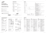
(1)
Loosen the three black M3L6 binding head screws in the back of the scanner unit and remove the two
black M3L6 binding head screws on top of the scanner unit.
Rear guide
Remove these M3L6 binding head screws
Loosen these M3L6 binder screws with washers
(2)
Slide the rear guide upward to detach it.
Reattaching the rear guide
(1)
Reattach the rear guide in the reverse order in which it was detached.
(2)
Make the necessary adjustments to make sure that the guide does not touch the drive roller and that no
gaps are wide enough for a document to slip into them.
CAUTION
When attaching the rear guide, insert a washer between the rear guide and the scanner unit base.
Rear guide
Scanner unit base
M3L6 binding head screw
Washer
CS1000-UM-251-03-9370
8-21