1
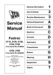
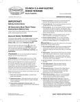
Service Manual
JCB 8250 Fastrac
Section 1 - General Information
Section 2 - Care and Safety
Section 3 - Maintenance
Section A - Optional Equipment
Section B - Body and Framework
Section C - Electrics
Section E - Hydraulics
Section F - Transmission
Section G - Brakes
Section H - Steering
Section S - Suspension
Section T - Engine
Publication No.
9803/8040-6
World Class
Customer Support
Copyright © 2004 JCB SERVICE. All rights reserved. No part of this publication may be reproduced, stored in a retrieval system, or transmitted in any form or by any other means,
electronic, mechanical, photocopying or otherwise, without prior permission from JCB SERVICE.
Issued by JCB Technical Publications, JCB Service, World Parts Centre, Beamhurst, Uttoxeter, Staffordshire, ST14 5PA, England. Tel +44 1889 590312 Fax +44 1889 593377
Section 1 - General Information
1-0
9803/8040-2
1-0
Section 1 - General Information
Contents
Page No.
Identifying the Machine
Serial Numbers ........................................................................................ 1 - 1
Serial Number Plate ........................................................................... 1 - 1
Standard Torque Settings
Zinc Plated Fasteners and Dacromet Fasteners .....................................
Introduction .........................................................................................
Zinc Plated Fasteners (golden finish) .................................................
Dacromet Fasteners (mottled silver finish) .........................................
Hydraulic Connections .............................................................................
'O' Ring Face Seal System .................................................................
'Torque Stop' Hose System ................................................................
1-3
1-3
1-4
1-5
1-6
1-6
1-9
Service Consumables
Sealing and Retaining Compounds ....................................................... 1 - 10
1-i
1-i
Section 1 - General Information
Contents
1 - ii
Page No.
1 - ii
Section 1 - General Information
Identifying the Machine
Serial Numbers
Identifying the Machine
Serial Numbers
Serial Number Plate
Unit Identification
Each machine has a serial number plate located at X. The
17 digit Vehicle Identification Number (VIN), and the serial
numbers of the engine and transmission are stamped on
the plate.
The serial number of each major unit is also stamped on
the unit itself as shown below. If a major unit is replaced by
a new one, the serial number on the plate will be wrong.
Either stamp the new number of the unit on the
identification plate, or simply stamp out the old number.
This will prevent the wrong unit number being quoted when
replacement parts are ordered.
Engine
M
Gearbox
N
Front axle
P
Rear axle
R
Fig 1.
Typical Vehicle Identification No. (VIN)
Fig 2.
A
Manufacturing code
B
Machine range
FT = Fastrac
C
Engine type
D
Transmission type
E
Vehicle max. speed
(gearbox & axle
combination)
Fig 3.
40 = 40 kph
50 = 50 kph
65 = 65 kph
F
1-1
Serial number
9803/8040-2
1-1
Section 1 - General Information
Identifying the Machine
Serial Numbers
N
Fig 4.
Fig 5.
Fig 6.
1-2
9803/8040-2
1-2
Section 1 - General Information
Standard Torque Settings
Zinc Plated Fasteners and Dacromet Fasteners
Introduction
Some external fasteners on Fastrac machines are
assembled using an improved type of corrosion resistant
finish. This type of finish is called Dacromet and replaces
the original Zinc and Yellow plating used on earlier
machines.
The two types of fasteners can be readily identified by
colour and part number suffix as follows:
Fastener Type
Colour
Part Number
Zinc and Yellow
Golden
finish
Z (e.g. 1315/3712Z)
Dacromet
Mottled
silver finish
D (e.g. 1315/3712D)
As the Dacromet fasteners have a lower torque setting
than the Zinc and Yellow fasteners, the torque figures used
must be relevant to the type of fasteners.
A Dacromet bolt should not be used in conjunction with a
Zinc and Yellow plated nut, as this could change the torque
characteristics of the torque settings further. For the same
reason, a Dacromet nut should not be used in conjunction
with a Zinc and Yellow plated bolt.
Dacromet bolts, due to their high corrosion resistance are
used in areas where rust could occur. Dacromet bolts are
only used for external applications. They are not used in
applications such as gearbox and engine joint seams or
internal applications.
Note: All bolts used on JCB machines are high tensile and
must not be replaced by bolts of a lesser tensile
specification.
1-3
9803/8040-2
1-3
Section 1 - General Information
Standard Torque Settings
Zinc Plated Fasteners and Dacromet Fasteners
Zinc Plated Fasteners (golden finish)
Metric - All Internal Hexagon
Headed Cap Screws
Use the values on these pages only where no torque
setting is specified in the text. Values are for dry threads
and may be within three per cent of the figures stated. For
lubricated threads the values should be REDUCED by one
third.
Diameter
Torque Settings
mm
Nm
kgf m
lbf ft
M3
2
0.2
1.5
M4
6
0.6
4.5
M5
11
1.1
8
M6
19
1.9
14
M8
46
4.7
34
M10
91
9.3
67
M12
159
16.2
117
M16
395
40
292
5
M18
550
56
406
770
79
568
1332 136
Metric Grade 8.8 Bolts
Size
Torque Settings
Nm
Diameter
(mm)
M5
(5)
kgf m lbf ft
Hexagon (A/F)
mm
8
7
0.7
M6
(6)
10
12
1.2
9
M20
M8
(8)
13
28
3.0
21
M24
M10
(10)
17
56
5.7
42
M12
(12)
19
98
10
72
M16
(16)
24
244
25
180
M18
(18)
27
350
36
258
M20
(20)
30
476
48
352
M24
(24)
36
822
84
607
M30
(30)
46
1633 166
1205
M36
(36)
55
2854 291
2105
Metric Grade 10.9 Bolts
Size
Torque Settings
Nm
1-4
983
Verbus Ripp Bolts
Fig 7.
Torque settings for these bolts are determined by the
application. Refer to the relevant procedure for the
required settings.
kgf m lbf ft
Diameter
(mm)
Hexagon (A/F)
mm
M6
(6)
8
16
1.6
12
M8
(8)
13
39
4
29
M10
(10)
17
78
8
57
M12
(12)
19
137
14
101
M16
(16)
24
343
35
253
M20
(20)
30
657
67
485
M24
(24)
36
1157 118
853
9803/8040-2
1-4
Section 1 - General Information
Standard Torque Settings
Zinc Plated Fasteners and Dacromet Fasteners
Dacromet Fasteners (mottled silver
finish)
Metric Grade 12.9 Bolts
Use the values on these pages only where no torque
setting is specified in the text.
Note: Dacromet fasteners are lubricated as part of the
plating process. Do not lubricate
Metric Grade 8.8 Bolts
Bolt size
Torque Settings
Dia.
Nm
kgf m lbf ft
M6 x 1.0
15
1.5
11
M8 x 1.25
40
4.1
29
M10 x 1.5
80
8.2
59
M12 x 1.75
133
13.6
98
M14 x 2
225
23
166
Bolt size
Torque Settings
M16 x 2
350
35.7
258
Dia.
Nm
kgf m lbf ft
M18 x 2.5
463
47
342
M6 x 1.0
9
0.9
7
M20 x 2.5
654
67
482
M8 x 1.25
22.5
2.3
17
M24 x 3
1125 115
830
M30 x 3.5
2247 229
1657
M10 x 1.5
47.5
4.8
35
M12 x 1.75
80
8.2
59
M14 x 2
133
13.6
98
M16 x 2
200
20.4
148
M18 x 2.5
278
28.4
205
M20 x 2.5
392
40
289
M24 x 3
675
69
498
M30 x 3.5
1348 138
994
Metric Grade 10.9 Bolts
Bolt size
Torque Settings
Dia.
Nm
kgf m lbf ft
M6 x 1.0
13.5
1.4
10
M8 x 1.25
35
3.6
26
M10 x 1.5
62.5
6.4
46
M12 x 1.75
115
11.7
85
M14 x 2
175
17.9
129
M16 x 2
300
30.6
221
M18 x 2.5
395
40
291
M20 x 2.5
559
57
412
M24 x 3
962
98
710
M30 x 3.5
1920 196
1-5
1416
9803/8040-2
1-5
Section 1 - General Information
Standard Torque Settings
Hydraulic Connections
Hydraulic Connections
T11-003
'O' Ring Face Seal System
Adaptors Screwed into Valve Blocks
Adaptor screwed into valve blocks, seal onto an 'O' ring
which is compressed into a 45° seat machined into the
face of the tapped port.
Table 1. Torque Settings - BSP Adaptors
BSP Adaptor
Hexagon (A/F)
Size
1-6
in.
mm
Nm
kgf m
lbf ft
1/4
19.0
18.0
1.8
13.0
3/8
22.0
31.0
3.2
23.0
1/2
27.0
49.0
5.0
36.0
5/8
30.0
60.0
6.1
44.0
3/4
32.0
81.0
8.2
60.0
1
38.0
129.0
13.1
95.0
1 1/4
50.0
206.0
21.0
152.0
Table 2. Torque Settings - SAE Connections
SAE Port Hexagon (A/F)
SAE Tube
Size
Thread Size
mm
Nm
kgf m
lbf ft
4
7/16 - 20
15.9
20.0 - 28.0
2.0 - 2.8
16.5 - 18.5
6
9/16 - 18
19.1
46.0 - 54.0
4.7 - 5.5
34.0 - 40.0
8
3/4 - 16
22.2
95.0 - 105.0
9.7 - 10.7
69.0 - 77.0
10
7/8 - 14
27.0
130.0 - 140.0
13.2 - 14.3
96.0 - 104.0
12
1 1/16 - 12
31.8
190.0 - 210.0
19.4 - 21.4
141.0 - 155.0
16
1 5/16 - 12
38.1
290.0 - 310.0
29.6 - 31.6
216.0 - 230.0
20
1 5/8
47.6
280.0 - 380.0
28.5 - 38.7
210.0 - 280.0
9803/8040-2
1-6
Section 1 - General Information
Standard Torque Settings
Hydraulic Connections
Hoses Screwed into Adaptors
Fig 8.
Hoses 8-B screwed into adaptors 8-A seal onto an `O' ring
8-C which is compressed into a 45° seat machined into the
face of the adaptor port.
BSP Hose Size
in.
1-7
Note: Dimension 8-D will vary depending upon the torque
applied.
Table 3. BSP Hose - Torque Settings
Hexagon (A/F)
mm
Nm
1/8
14.0
14.0 - 16.00
1.4 - 1.6
10.3 - 11.8
1/4
19.0
24.0 - 27.0
2.4 - 2.7
17.7 - 19.9
3/8
22.0
33.0 - 40.0
3.4 - 4.1
24.3 - 29.5
1/2
27.0
44.0 - 50.0
4.5 - 5.1
32.4 - 36.9
5/8
30.0
58.0 - 65.0
5.9 - 6.6
42.8 - 47.9
3/4
32.0
84.0 - 92.0
8.6 - 9.4
61.9 - 67.8
1
38.0
115.0 - 126.0
11.7 - 12.8
84.8 - 92.9
1 1/4
50.0
189.0 - 200.0
19.3 - 20.4
139.4 - 147.5
1 1/2
55.0
244.0 - 260.0
24.9 - 26.5
180.0 - 191.8
9803/8040-2
kgf m
lbf ft
1-7
Section 1 - General Information
Standard Torque Settings
Hydraulic Connections
Adaptors into Component Connections with Bonded Washers
Table 4. BSP Adaptors with Bonded Washers - Torque Settings
BSP Size
1-8
in.
Nm
kgf m
lbf ft
1/8
20.0
2.1
15.0
1/4
34.0
3.4
25.0
3/8
75.0
7.6
55.0
1/2
102.0
10.3
75.0
5/8
122.0
12.4
90.0
3/4
183.0
18.7
135.0
1
203.0
20.7
150.0
1 1/4
305.0
31.0
225.0
1 1/2
305.0
31.0
225.0
9803/8040-2
1-8
Section 1 - General Information
Standard Torque Settings
Hydraulic Connections
'Torque Stop' Hose System
Fig 9.
`Torque Stop' Hoses 9-B screwed into adaptors 9-A seal
onto an 'O' ring 9-C which is compressed into a 45° seat
machined in the face of the adaptor port. To prevent the 'O'
ring being damages as a result of over tightening, 'Torque
Stop' Hoses have an additional shoulder 9-D, which acts
as a physical stop.
Note: Minimum dimension 9-E fixed by shoulder 9-D.
Table 5. BSP `Torque Stop' Hose - Torque Settings
BSP Hose Size
Hexagon (A/F)
1-9
in.
mm
Nm
kgf m
lbf ft
1/8
14.0
14.0
1.4
10.0
1/4
19.0
27.0
2.7
20.0
3/8
22.0
40.0
4.1
30.0
1/2
27.0
55.0
5.6
40.0
5/8
30.0
65.0
6.6
48.0
3/4
32.0
95.0
9.7
70.0
1
38.0
120.0
12.2
89.0
1 1/4
50.0
189.0
19.3
140.0
1 1/2
55.0
244.0
24.9
180.0
9803/8040-2
1-9
Section 1 - General Information
Service Consumables
Sealing and Retaining Compounds
Service Consumables
Sealing and Retaining Compounds
T11-001_3
Table 6.
Type
Description
Part No.
Quantity
JCB Multi-Gasket
A medium strength sealant suitable for all sizes of
4102/1212
gasket flanges, and for hydraulic fittings of 25-65 mm
diameter.
50 ml
JCB High Strength Threadlocker
A high strength locking fluid for use with threaded
4102/0551
components. Gasketing for all sizes of flange where
the strength of the joint is important.
50 ml
JCB Retainer (High Strength)
For all retaining parts which are unlikely to be
dismantled.
4101/0651
50 ml
JCB Threadlocker and Sealer
A medium strength locking fluid for sealing and
retaining nuts, bolts, and screws up to 50 mm
diameter, and for hydraulic fittings up to 25 mm
diameter.
4101/0250
10 ml
4101/0251
50 ml
JCB Threadlocker and Sealer
(High Strength)
A high strength locking fluid for sealing and retaining 4101/0550
nuts, bolts, and screws up to 50 mm diameter, and 4101/0552
for hydraulic fittings up to 25 mm diameter.
10 ml
200 ml
JCB Threadseal
A medium strength thread sealing compound.
4102/1951
50 ml
JCB Activator
A cleaning primer which speeds the curing rate of
anaerobic products.
4104/0251
200 ml (Aerosol)
4104/0253
1 ltr (Bottle)
JCB Cleaner/Degreaser
For degreasing components prior to use of
anaerobic adhesives and sealants.
4104/1557
400 ml (Aerosol)
Direct Glazing Kit
For one pane of glass; comprises of:
993/55700
– 1 x Ultra Fast Adhesive (310 ml)
– 1 x Active Wipe 205 (30 ml)
– 1 x Black Primer 206J (30 ml)
– plus applicator nozzle etc.
Ultra Fast Adhesive
For direct glazing.
4103/2109
310 ml
Active Wipe 205
For direct glazing.
4104/1203
250 ml
Black Primer 206J
For direct glazing.
4201/4906
30 ml
Clear Silicone Sealant
To seal butt jointed glass.
4102/0901
Plastic to Metal Bonder
To seal plastic to metal joints.
4103/0956
50 g
Black Polyurethane Sealant
To finish exposed edges of laminated glass.
4102/2309
310 ml
1 - 10
9803/8040-2
1 - 10
Section 2 - Care and Safety
2-0
9803/8040-2
2-0
Section 2 - Care and Safety
Contents
Page No.
Safety Check List
Introduction .............................................................................................. 2 - 1
Safety First .............................................................................................. 2 - 2
Safety - Yours and Others .................................................................. 2 - 2
General Safety ................................................................................... 2 - 2
Operating Safety ..................................................................................... 2 - 4
Maintenance Safety ................................................................................. 2 - 9
2-i
2-i
Section 2 - Care and Safety
Contents
2 - ii
Page No.
2 - ii
Section 2 - Care and Safety
Safety Check List
Introduction
T1-006
!MWARNING
Study the Operator Manual before starting the
machine. You must understand and follow the
instructions in the Operator Manual. You must
observe all relevant laws and regulations. If you are
unsure about anything, ask your JCB dealer or
employer. Do not guess, you or others could be killed
or seriously injured.
INT-1-1-1_2
In this publication and on the machine, there are safety
notices. Each notice starts with a signal word. The signal
word meanings are given below.
!MDANGER
Denotes an extreme hazard exists. If proper
precautions are not taken, it is highly probable that the
operator (or others) could be killed or seriously
injured.
INT-1-2-1
!MWARNING
Denotes a hazard exists. If proper precautions are not
taken, the operator (or others) could be killed or
seriously injured.
INT-1-2-2
!MCAUTION
Denotes a reminder of safety practices. Failure to
follow these safety practices could result in injury to
the operator (or others) and possible damage to the
machine.
INT-1-2-3
2-1
9803/8040-1
2-1
Section 2 - Care and Safety
Safety Check List
Safety First
Safety First
As well as the warnings in this chapter, specific warnings
are given throughout the book. This section is designed to
give a safety code for use of the machine generally and for
operation and maintenance practices.
Safety - Yours and Others
INT-1-3-1_3
All machinary can be hazardous. When a machine is
correctly operated and properly maintained, it is a safe
machine to work with. But when it is carelessly operated or
poorly maintained it can become a danger to you (the
operator) and others.
In this manual and on the machine you will find warning
messages. Read and understand them. They tell you of
potential hazards and how to avoid them. If you do not fully
understand the warning messages, ask your employer or
JCB distributor to explain them.
But safety is not just a matter of responding to the
warnings. All the time you are working on or with the
machine you must be thinking what hazards there might be
and how to avoid them.
General Safety
!MWARNING
Operator Manual
You and others can be injured if you operate or
maintain the machine without first studying the
Operator Manual. Read the safety instructions before
operating the machine. If you do not understand
anything, ask your employer or JCB dealer to explain
it. Keep the Operator Manual clean and in good
condition. Do not operate the machine without an
Operator Manual in the cab, or if there is anything on
the machine you do not understand.
INT-1-3-2_2
!MWARNING
Care and Alertness
All the time you are working with or on the machine,
take care and stay alert. Always be careful. Always be
alert for hazards.
INT-1-3-5
!MWARNING
Do not work with the machine until you are sure that you
can control it.
Do not start any job until you are sure that you and those
around you will be safe.
If you are unsure of anything, about the machine or the job,
ask someone who knows. Do not assume anything.
Remember
BE CAREFUL
T1-007
Clothing
You can be injured if you do not wear the proper
clothing. Loose clothing can get caught in the
machinery. Wear protective clothing to suit the job.
Examples of protective clothing are: a hard hat, safety
shoes, safety glasses, a well fitting overall, earprotectors and industrial gloves. Keep cuffs fastened.
Do not wear a necktie or scarf. Keep long hair
restrained.
INT-1-3-6
BE ALERT
!MWARNING
BE SAFE
Alcohol and Drugs
It is extremely dangerous to operate machinery when
under the influence of alcohol or drugs. Do not
consume alcoholic drinks or take drugs before or
while operating the machine or attachments. Be aware
of medicines which can cause drowsiness.
INT-1-3-9_2
2-2
9803/8040-1
2-2
Section 2 - Care and Safety
Safety Check List
Safety First
!MWARNING
!MDANGER
Feeling Unwell
Do not attempt to operate the machine if you are
feeling unwell. By doing so you could be a danger to
yourself and those you work with.
Lightning
Lightning can kill you. Do not use the machine if there
is lightning in your area.
5-1-1-2
8-1-2-4
!MWARNING
!MWARNING
Mobile Phones
Switch off your mobile phone before entering an area
with a potentially explosive atmosphere. Sparks in
such an area could cause an explosion or fire
resulting in death or serious injury.
Switch off and do not use your mobile phone when
refuelling the machine.
Machine Modifications
This machine is manufactured in compliance with
legislative and other requirements. It should not be
altered in any way which could affect or invalidate any
of these requirements. For advice consult your JCB
Distributor.
INT-1-3-10_2
INT-3-3-9
!MWARNING
Lifting Equipment
You can be injured if you use faulty lifting equipment.
Make sure that lifting equipment is in good condition.
Make sure that lifting tackle complies with all local
regulations and is suitable for the job. Make sure that
lifting equipment is strong enough for the job.
INT-1-3-7
!MWARNING
Raised Equipment
Raised equipment can fall and injure you. Do not walk
or work under raised equipment unless safely
supported.
13-1-1-6
!MWARNING
Raised Machine
NEVER position yourself or any part of your body
under a raised machine which is not properly
supported. If the machine moves unexpectedly you
could become trapped and suffer serious injury or be
killed.
INT-3-3-7_1
2-3
9803/8040-1
2-3
BUY NOW