1
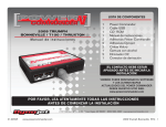
Options
Pressure input
Map Switch
Output
Gear/Speed Input
Allows the map to be trimmed
based on pressure/boost input
Allows the user to change
between 2 maps via a
handlebar mount switch
Allows 2 relays to be
activated based on RPM and
throttle position
Allows the map to be trimmed
based on gear position and/or
display speed
FOR MODEL SPECIFIC INSTALLATION INSTRUCTIONS AND
CONFIGURATION FILES GO TO WWW.POWERCOMMANDER.COM.
Installation
•
This guide will give you a general overview to the use of the HUB and
HUB accessories. Any combination of the HUB accessories can work in
conjunction with each other. The HUB can be used with or without the
Ignition Module.
•
Connect the hub to the female expansion port of either the PCIII USB or
the Ignition Module.
•
For the Multi-Function Hub to operate properly with the PCIIIUSB you
will need to update the PCIII USB to firmware version 2.1.2 and use
software version 3.1.8 or higher.
•
To determine your current firmware version go to VIEW - POWER
COMMANDER INFO in the Control Center software. If your current firmware
is version 1.0.0.20 or higher then you can update your firmware by going to POWER COMMANDER TOOLS - UPDATE
FIRMWARE. The firmware needed for use with the Hub can be downloaded from the enclosed CD or our website,
www.powercommander.com.
•
If your firmware version is 1.0.0.19 or lower then you will need the firmware programmer to update your PCIII USB. This
programmer can be found in some Ignition Modules or the HDREV kit. Follow the enclosed UPDATE instructions to
perform this step.
•
If you do not have one of the programmers and you cannot find a Tuning Center to update your PCIII USB the unit can
be sent in to Dynojet to be updated. Please call 800-992-4993 for instructions. You can also purchase a programmer,
part #PCPROG, which will allow you to update your PCIII USB and Ignition Module.
•
If you are using an Ignition Module then you will need to use fimware 2.1.2 or newer in the Ignition Module. If your
current firmware is lower than 2.1.2 use the programmer that came with the Ignition Module to update it. Follow the
enclosed UPDATE instructions to perform this step.
www.powercommander.com
Multi-Function Hub - 1
Speed Input
(harness #76950212)
Most modern fuel injected bikes use a transmission speed
sensor. The Hub can be tapped into this sensor to display
vehicle speed and also to be used as a gear position
display for bikes that do not have a rotary type sensor
4
1
Locate the signal wire of the speed sensor (refer to the
service manual, NOTE section of this guide, or
www.powercommander.com).
2
Crimp the supplied wire tap to this wire.
3
Connect the BROWN wire from the HUB harness to the
wire tap.
If there is not a configuration file for your bike then you will need to calculate the speed input manually. Go to POWER
COMMANDER TOOLS - HUB CONFIGURATION. Type in a target speed (20-40mph). The bike will need to be put in
gear and held at the target speed. Once the speed is stable click on CALC. The current speed should now read the
same as the dash. For the most accurate results this is best done on a dynamometer although this can be achieved
with the bike on a rear stand.
• The Speed Scaler can be used to fine tune the speedometer reading in the PCIII software or the LCD display. If you
were using a GPS you could move the scale until the LCD display coincided with the GPS display.
Gear Position
(harness #76950212)
Gear Position can be calibrated
on bikes that have a rotary
switch and/or a transmission
speed sensor.
If desired both the speed input
and gear input could be used
simultaneously
1
If your bike has a rotary gear position sensor then
you will need to determine which wire from the sensor
is the signal (refer to the service manual, NOTE section of
this guide or www.powercommander.com). Most
Kawasakis and Suzukis use a rotary type sensor.
2
Crimp the supplied wire tap to this wire.
3
Connect the GREY wire from the Gear Position Hub harness to the wire tap. If your bike does NOT have a rotary type
sensor then the GREY wire will not be used.
4
To setup the Gear Position Input go to POWER COMMANDER TOOLS - HUB CONFIGURATION - GEAR SETUP. Click
on the drop menu at the top, center of the screen. Choose Gear Position if you are connected to a rotary type sensor.
5
Put the bike in first gear and click on the “Auto” box for first gear. Repeat this step for each gear. This is best performed
on a dyno but can also be done with the bike on a rear stand. The Green slider bar should be at different ranges of the
scale for each gear. If the slider bar does not move then you may not have a good connection at the rotary switch/speed
sensor. Click OK when done.
6
If you are using the speed input for calculating gear position then choose Speed calc from the drop down menu. Repeat
step 5. Make sure you have calibrated your speed input before performing this step.
7
After the gear position has been calibrated the main screen of the software will show current gear position. If the HUB is
connected to the Dynojet LCD display gear position will also be shown.
www.powercommander.com
Multi-Function Hub - 2
Gear Position Trim Feature
• After you have setup the gear position either via the rotary
sensor or speed input the software will allow you to trim the
base map for both fuel and ignition (if the Ignition Module
is installed).
• Go to POWER COMMANDER TOOLS - HUB
CONFIGURATION - GEAR TRIMS.
• The software will allow you to trim your base map +/- 50% of
fuel and +/- 10 degrees of timing per gear. The software will
only allow you a total of +10 degrees of timing so if your base
map has a value of 10 in any cell the gear trim will not allow
you to advance any further.
If you had a +5 anywhere in your base timing map and you tried to move one of the gear trims for the timing to more
than +5 the software would limit you also.
•
Click on the slider bar and drag to the desired setting for each gear. The offset value will be shown underneath each
scale. Click OK when done.
•
The Gear Position Trim values will be added to the base map values and will be displayed under fuel change and/or
timing on the main software screen.
Relay Trigger
(harness #76950506)
The Hub can trigger up to 2
output signals such as an
indicator light, Nitrous relay,
or shift light.
1
Locate the ground wire of the device you want to trigger.
2
Attach the ground from the device to the HUB harness.
3
Attach the WHITE/YELLOW wire from the Hub harness to trigger Output Channel 1.
4
Attach the WHITE/GREEN wire from the Hub harness to trigger Output Channel 2 (if needed).
5
Attach the BLACK wire from the Hub harness to a chassis ground or the negative side of the battery.
6
Go to POWER COMMANDER TOOLS - HUB CONFIGURATION - OUTPUT SETUP. The trigger can be
activated based on Throttle Position and/or RPM. For example; you could trigger a NOS relay to only be activated
above 80% throttle and above 7000rpm. Click OK when setup is done.
• The current limit for each channel is 3 amps.
www.powercommander.com
Multi-Function Hub - 3
Pressure Input
(harness #76950012)
The Pressure input harness
allows you to trim the base
fuel/timing map based on a
0-5v input signal line. In most
cases this will be used to offset
the fuel curve for a turbo
application.
•
The pressure harness has 3 wires. YELLOW = signal (0-5
volt),BLACK/WHITE = ground, WHITE/RED = (5 volt).
•
You will first need to determine the parameters of the
pressure sensor that you are using. If the sensor reads a
maximum of 10lbs of pressure then you will need to determine what the voltages correspond to at 0lbs and at 10lbs
(relative pressure). Every point in between should be a linear reading. Refer to the notes section for readings of
specific sensors.
•
Once you have determined the parameters of your sensor you can alter the HUB settings accordingly. For example, if
you wanted the HUB to add 10% of fuel at 5lbs of boost then move the scale to +10% fuel to the voltage that you
determined your sensor would be at when it read 5lbs of boost.
•
You can also trim the ignition timing according to a pressure input if desired.
•
The HUB will allow you +/- 50% of fuel and +/-10 degrees of timing on top of your base map. The software will only
allow you a total of +10 degrees of timing so if your base map has a value of 10 in any cell the pressure trim will not
allow you to advance any further.
•
The raw voltage of this sensor will be displayed on the main software screen under Trim Voltage.
•
If you are using a Wide Band Commander you can input the 0-5v signal from it (see page 10 of the WBC install) and
display this in the Power Commander Control Center software or on the LCD display. This voltage correlates to Petrol
air/fuel ratio. Refer to the chart in notes section. This will allow you to read real time air/fuel ratio and be able to log this
data in the LCD Display. The BLACK/WHITE wire and the WHITE/RED wire does NOT need to be connected when
inputting the 0-5v signal from the WBC.
Map Switch
(harness #76950320)
Map switch is shown mounted
to the handlebar via our optional
map switch bracket part
#61329304
Note: Bracket is for 7/8” bars.
•
The map switch will allow you to toggle back and forth
between two maps that are stored within the Power
Commander.
•
To enable this feature go to POWER COMMANDER
TOOLS - SET NUM MAPS - 2 MAPS.
•
When this feature is enabled when you click on Send Map or Get Map you will be prompted as to what map you want to
send or receive. The map that is currently active in the Power Commander will be displayed on the right hand side of
the software.
•
When first connecting to the software it will automatically retrieve the map that the switch correlates to.
•
When tuning the PCIII USB and using either INSERT (on keyboard) or SEND TABLE and you are viewing the map that
is NOT current you will be prompted that you are about to alter the incorrect map. Follow the instructions shown on the
screen to continue.
www.powercommander.com
Multi-Function Hub - 4
Notes
LOAD/SAVE config
•
Under Power Commander Tools - Hub Configuration, you will see you have the option of either LOAD or SAVE config
files. We have compiled the setup information needed for various models which saves you setup time when using the
SPEED and/or GEAR input harnesses.
These configuration files can be found at www.powercommander.com or on the enclosed CD. Download these files to
your computer and when you click on LOAD config from the HUB setup it will prompt you to find this file. Once the file is
loaded the necessary settings will be filled in under SPEED and GEAR input. These settings can be loaded even if you
are not using these harnesses though no data will be displayed.
•
We will be constantly adding new models to the list so keep an eye on the website for new updates.
GEAR/SPEED input
•
Most of the Suzuki and Kawasaki models have a rotary style gear position indicator. This sensor can be located on the
shift drum inside the transmission which outputs different voltages in each gear. When connecting the Gear input
harness from the HUB to this style of sensor it will give you a very stable gear reading. This sensor will normally have 3
wires. One wire is Ground, one wire is constant 5 volts, and the wire you need to connect to will have variable voltage
when the bike is running and you shift thru the gears.
•
If you are using a timing retard device that connects to the gear position you will need to base the HUB gear position on
the speed input.
•
The speed output sensor will normally have 3 wires. One wire is Ground, one wire is constant 5 volts and the one you
need to connect to will have variable 0-5volts when the bike is running and the rear wheel is spinning.
•
Here is a list of the location of these wires on some models. Check the website for a more updated list.
Model
Speed Input
Gear Input
Honda CBR1000RR 05-06
Pink wire on ECU R.H side
Honda F4i
Pink wire - Left rear of engine
PINK/GRN/BLK
Honda RC51
PINK-GREEN wire under seat on R.H side
Sensor is on rear right hand side of engine
N/A
Kawasaki ZX6R 07
PINK wire from sensor on c/s cover
PINK/YELLOW/BLACK
GRN-RED wire on black 6 pin
connector - R.H side of bike under tank
Kawasaki ZX10 04-05
Yellow wire of black 3 pin connector
YELLOW/PINK/BLK
GRN-RED wire underneath throttle
bodies on left side - GREEN 4 pin connector
Kawasaki ZX10 06
BLUE-YELLOW wire of black 3 pin conn
near the c/s sprocket
BLU/BLU-YEL/BLK-YEL
GRN-RED wire on 10 pin grey
connector under fuel tank
Suzuki GSXR 01-06
Pink wire on black 3 pin connector
BLK-RED/BLK-WHT/PINK
Pink wire on white 3 pin connector
BLU/PINK/BLK-WHT
Suzuki SV650
Pink wire - connector is located in front of the
airbox - comes from frt wheel
N/A
Pink wire on white 3 pin connector under fuel tank
BLU/PINK/BLK-WHT
Yamaha R6 03-06
Pink wire from sensor on center rear of engine
PINK/ORANGE/BLK-WHT
N/A
Yamaha R1 2007
Pink wire on white 3 pin connector under fuel tank
PINK/OR-RED/BLK-WHT
N/A
Harley Softail 01-06
White wire - R.H side of trans
WHT/RED/BLK
N/A
www.powercommander.com
Multi-Function Hub - 5
Volts
0
0.25
0.5
0.75
1
1.25
1.5
1.75
2
2.25
2.5
2.75
3
3.25
3.5
3.75
4
4.25
4.5
4.75
5
GM 2bar
Pressure
0
1.465
2.93
4.395
5.86
7.325
8.79
10.255
11.72
13.185
14.65
16.115
17.58
19.631
20.51
21.975
23.44
24.905
26.37
27835
29.3
GM 3bar
Pressure
0
2.2925
4.585
6.8775
9.17
11.4625
13.755
16.0475
18.34
20.6325
22.925
25.2175
27.51
29.8025
32.095
34.3875
36.68
38.9725
41.265
43.5575
45.85
Pressure Sensors
•
The Trim Voltage can be based on various 0-5 volt input sensors. Most sensors
should come with a spec sheet that shows you the breakdown of the output of the
sensor at various voltages. The HUB has a resolution of .25v from 0-5 volts.
•
To help you setup this feature here is the breakdown for the GM sensors. This chart
shows absolute pressure.
WBC voltages
•
If you are using a Wide Band Commander you can input
the 0-5v signal from it and display this in the Power
Commander Control Center software or on the LCD
display. This voltage correlates to Petrol air/fuel ratio.
This will allow you to read real time air/fuel ratio and be
able to log this data in the LCD Display.
•
Connect the WHITE/YELLOW wire from the WBC to the
YELLOW wire of the HUB pressure harness. Connect
the WHITE/GREEN wire and BLACK/WHITE wire from
the WBC together and attach them to a good chassis
ground. If you use this configuration you will NOT be
able to input a pressure signal and offset
the map at the same time.
•
Once you have the Trim Voltage displaying the output
from the WBC use this chart to reference Petrol air/fuel
ratio.
www.powercommander.com
WBC Volts Petrol AFR
0
0.0625
0.125
0.1875
0.25
0.3125
0.375
0.4375
0.5
0.5625
0.625
0.6875
0.75
0.8125
0.875
0.9375
1
1.0625
1.125
1.1875
1.25
1.3125
1.375
1.4375
1.5
1.5625
1.625
1.6875
1.75
1.8125
1.875
1.9375
2
2.0625
2.125
2.1875
2.25
2.3125
2.375
2.4375
10
10.1
10.2
10.3
10.4
10.5
10.6
10.7
10.8
10.9
11
11.1
11.2
11.3
11.4
11.5
11.6
11.7
11.8
11.9
12
12.1
12.2
12.3
12.4
12.5
12.6
12.7
12.8
12.9
13
13.1
13.2
13.3
13.4
13.5
13.6
13.7
13.8
13.9
WBC Volts Petrol AFR
2.5
2.5625
2.625
2.6875
2.75
2.8125
2.875
2.9375
3
3.0625
3.125
3.1875
3.25
3.3125
3.375
3.4375
3.5
3.5625
3.625
3.6875
3.75
3.8125
3.875
3.9375
4
4.0625
4.1875
4.25
4.3125
4.375
4.4375
4.5
4.5625
4.625
4.6875
4.75
4.8125
4.875
4.9375
5
14
14.1
14.2
14.3
14.4
14.5
14.6
14.7
14.8
14.9
15
15.1
15.2
15.3
15.4
15.5
15.6
15.7
15.8
15.9
16
16.1
16.2
16.3
16.4
16.5
16.7
16.8
16.9
17
17.1
17.2
17.3
17.4
17.5
17.6
17.7
17.8
17.9
18
Multi-Function Hub - 6
In order for your new HUB to operate you MAY have to update
your Power Commander and/or Ignition Module.
• If your PCIII USB firmware is 1.0.0.19 or lower then follow these instructions.
• If your Ignition Module firmware is 2.1.1 or lower then follow these instructions
TO START:
Insert the provided CD into your computer. This program will start automatically.
Click on Power Commander firmware update. This will bring up a screen that will
step you thru the update of your PCIII. If you have a Harley Davidson click on
Harley Davidson firmware update.
To update your Ignition Module click on Ignition Module Firmware Update.
NOTE:
It is necessary to have the latest Control Center software in order to communicate
to the Power Commander. To update the software, click on Power Commander
Software Update.
9v adapter
connection
Click here
Programmer
USB cable
STEP 1
1 Connect your USB cable to your computer and then to the programmer.
Connect the 9v battery adapter to the programmer.
Connect the white, male connector from the programmer to the PCIII
expansion port. If you have hooked everything up in the correct sequence the
light on the PCIII will either NOT be lit or you will have 1 light at the top of the
scale and one at the bottom.
STEP 2
2 The “Update Firmware” button will now be active. Click on this button
and a blue scroll bar will start. Wait until done.
If you should get a communication error 8001 then click on Update
Firmware again until the update finishes.
DO NOT have the Ignition Module connected to the PCIII at this time.
Click here
STEP 3
3 Unplug the USB cable from the programmer and plug it directly into the USB
port of the Power Commander.
The “Update Settings” button will now become active. Click on this button and
wait until done.
www.powercommander.com
STEP 4
4 When the unit has been updated you will get a confirmation of “Power
Commander successfully updated”. You can now disconnect the
programmer.
5 Follow steps 1& 2 for the Ignition Module if needed. Make sure that
the programmer is connected to the Ignition Module and that the
Ignition Module is NOT connected to the PCIII.
Multi-Function Hub - 7