1
Service
This manual is to be used by qualified appliance
technicians only. Maytag does not assume any
responsibility for property damage or personal
injury for improper service procedures done by
an unqualified person.
Side-by Side
Refrigerators
This Base Manual covers general information
Refer to individual Technical Sheet
for information on specific models
This manual includes, but is
not limited to the following:
Maytag
MSB1542ARW/A
MSB2354ARW/A
MSB2554ARW/A
MSD2142ARW/A
MSD2143ARW/A
MSD2346AEW/A/B
MSD2354ARW/A
MSD2356AEW/A/B
MSD2543ARW/A
MSD2554ARW/A
MSD2556AEW/A/B
MSD2754ARW/A
MSD2756AEA/W/B
MSD2757AEA/W/B
MSD2758DRW/B/Q
MSD2759DRW/B/Q
MSD2959DRW/B/Q
Jenn-Air
JCB2388ARW/A/B
JCB2388ATW/A/B
JCD2289AEW/A/BF/G/K/R/S/U
JCD2289ATW/B
JSD2388AEW/A/B
JSD2574ARW/B
JSD2588AEW/A/B
JSD2774ARW/B
JSD2789AEW/A/B/S
JSD2789ATW/B
JSD2989AEW/A/B
Admiral
ASD2514ARW/A
Magic Chef
CSB2121ARW
CSB2122ARW/A
CSB2323ARW/A
CSD2122ARW/A
CSD2123ARW/A
CSD2324ARW/A
CSD2325ARW/A
CSD2524ARW/A
CSD2525ARW/A
CSD2725ARW/A
16010154
November 2003
SAFETY PRECAUTIONS
THIS MANUAL IS TO BE USED ONLY BY A MAYTAG AUTHORIZED SERVICE TECHNICIAN
FAMILIAR WITH AND KNOWLEDGEABLE OF PROPER SAFETY AND SERVICING PROCEDURES AND POSSESSING HIGH QUALITY TESTING EQUIPMENT ASSOCIATED WITH
MICROWAVE, GAS, AND ELECTRICAL APPLIANCE REPAIR.
ALL INDIVIDUALS WHO ATTEMPT REPAIRS BY IMPROPER MEANS OR ADJUSTMENTS,
SUBJECT THEMSELVES AND OTHERS TO THE RISK OF SERIOUS OR FATAL INJURY.
USE ONLY GENUINE MAYTAG APPROVED FACTORY REPLACEMENT COMPONENTS.
16010154
©2003 Maytag Corporation
CONTENTS
i
INTRODUCTION
This refrigeration service manual provides the information necessary to service Side-bySide model refrigerators.
NOTE: ALL MODELS COVERED IN THIS SERVICE MANUAL USE R134A REFRIGERANT.
The manual is printed in loose leaf format. Each part of this manual is divided into sections relating to a general group of components and each section is subdivided into
various parts describing a particular component or service procedure.
The subdividing of the subject matter, plus the loose leaf form, will facilitate the updating
of the manual as new models, and new or revised components of service procedures
are introduced.
Each page of this manual will be identified in the lower right hand corner. As new or
revised pages are published, it will be easy to keep the manual up to date.
This serivce manual is a valuable service tool and care should be taken to keep it up to
date by prompt and proper filing of subsequent pages as they are issued.
ALL "E" MODELS ARE ENERGY MODELS, AND HAVE A PREMIUM SOUND PACKAGE.
16010154
©2003 Maytag Corporation
CONTENTS
ii
16010154
©2003 Maytag Corporation
CONTENTS
iii
CONTENTS
GENERAL SAFETY PRECAUTIONS ............................................................... i
INTRODUCTION ..................................................................................... ii
CONTENTS .......................................................................................... iv
SECTION 1. GENERAL INFORMATION ....................................................... 1-1
ELECTRICAL REQUIREMENTS ........................................................................ 1-1
SAFETY PRECAUTIONS ................................................................................ 1-1
Grounding Instructions ............................................................................. 1-1
FORCED AIR SYSTEMS ................................................................................ 1-2
AIR FLOW - FORCED AIR SYSTEMS ................................................................. 1-2
CHECKING OPERATION ................................................................................ 1-3
TOOLS NEEDED FOR R134A SEALED SYSTEM REPAIR ........................................ 1-4
ADDITIONAL SYSTEM INFORMATION .............................................................. 1-5
R134A SEALED SYSTEM SERVICE PROCEDURE ................................................. 1-7
REFRIGERATION SYSTEM ............................................................................. 1-8
REFRIGERATION CYCLE ................................................................................ 1-9
D I A G N O S I S .............................................................................................. 1-10
SEALED SYSTEM DIAGNOSIS ....................................................................... 1-10
LEAK TESTING ........................................................................................... 1-12
C O M P O N E N T S .......................................................................................... 1-13
Drier .................................................................................................... 1-13
Condenser ............................................................................................ 1-13
Yoder Loop............................................................................................ 1-14
Evaporator ............................................................................................ 1-15
Heat Exchanger ...................................................................................... 1-15
Compressor .......................................................................................... 1-15
SYSTEM FLUSH ......................................................................................... 1-15
SEALED SYSTEM REPAIR SUMMARY ............................................................. 1-16
SYSTEM FLUSH PROCEDURE........................................................................ 1-16
SWEEP AND FINAL CHARGE ........................................................................ 1-19
SECTION 2. COMPONENTS .................................................................... 2-1
COMPRESSOR REPLACEMENT ......................................................................
REPLACING THE COMPRESSOR .....................................................................
CONDENSER REPLACEMENT .........................................................................
ELECTRICAL SYSTEM...................................................................................
Testing the Compressor Direct ....................................................................
Overload Protector...................................................................................
Testing the Overload Protector ....................................................................
PTC STARTING DEVICE AND RUN CAPACITOR ...................................................
PTC Device Replacement ...........................................................................
RUN CAPACITOR .........................................................................................
Testing the Capacitor ................................................................................
Alternate Method Using Ohmmeter ..............................................................
TEMPERATURE CONTROL .............................................................................
Checking Operating Temperatures ...............................................................
Temperature Control Replacement ...............................................................
16010154
©2003 Maytag Corporation
CONTENTS
2-1
2-1
2-2
2-4
2-4
2-5
2-5
2-6
2-7
2-7
2-7
2-7
2-8
2-8
2-9
iv
AUTO DAMPER CONTROL MODELS ................................................................. 2-10
Checking the Auto Damper ........................................................................ 2-11
Auto Damper Control Replacement .............................................................. 2-11
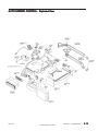
AUTO DAMPER CONTROL - Exploded View ........................................................ 2-12
DEFROST TIMER ......................................................................................... 2-13
Checking the Defrost Timer ........................................................................ 2-14
Timer Replacement .................................................................................. 2-14
ADAPTIVE DEFROST CONTROL ...................................................................... 2-14
Checking the Adaptive Defrost Control .......................................................... 2-15
AIR FLOW - FORCED AIR SYSTEMS .................................................................. 2-15
DEFROST HEATER REPLACEMENT .................................................................. 2-17
DEFROST THERMOSTAT REPLACEMENT ........................................................... 2-17
CONDENSER FAN MOTOR ............................................................................. 2-18
To Check Condenser Motor Direct ................................................................ 2-18
Condenser Fan Motor Replacement .............................................................. 2-19
FREEZER FAN MOTOR .................................................................................. 2-19
Freezer Fan Motor Diagnosis ...................................................................... 2-19
Freezer Fan Motor Replacement .................................................................. 2-20
SECTION 3. CABINET & RELATED COMPONENTS ........................................ 3-1
ADJUSTABLE CANTILEVER SHELVES............................................................... 3-1
ADJUSTABLE CANTILEVER SHELF TRIMS ......................................................... 3-1
CABINET DOORS AND ASSOCIATED PARTS ..................................................... 3-1
Inner Door Liner Replacement .................................................................... 3-1
Outer Door Panel Replacement ................................................................... 3-2
FRONT WHEEL ASSEMBLY ............................................................................ 3-2
CABINET LEVELING ..................................................................................... 3-2
DOOR SEAL ............................................................................................... 3-3
TOE-IN & TOE-OUT ADJUSTMENTS ................................................................. 3-3
HINGE ADJUSTMENTS ................................................................................. 3-3
DOOR ALIGNMENT ...................................................................................... 3-4
DOOR SWITCH ........................................................................................... 3-4
WATER/ICE DISPENSER FREEZER DOOR REMOVAL ............................................ 3-4
FOUNTAIN ASSEMBLY - Manual Slide Control .................................................... 3-6
Ice and Water Fountain Bracket Assembly Removal .......................................... 3-6
Checking and Replacing the Crusher and Water/Cube Switch ............................. 3-6
Checking and Replacing the Actuaring Switch ................................................ 3-7
Fountain Heater ....................................................................................... 3-7
PC BOARD CHECKS ..................................................................................... 3-8
Fountain Door Delay ................................................................................. 3-7
Excessive Door Delay ................................................................................ 3-7
Short Door Delay ..................................................................................... 3-7
FOUNTAIN ASSEMBLY - Electronic Control ....................................................... 3-8
Ice and Water Fountain Bracket Removal ....................................................... 3-8
Fountain Bracket Assembly ........................................................................ 3-9
Checking and Replacing the Actuator Switch .................................................. 3-9
Electronic Control Board Troubleshooting ...................................................... 3-9
ICE CRUSHER BIN AND SHELF ASSEMBLY ....................................................... 3-10
ICE/CRUSHER BIN SHELF ENCLOSURE ASSEMBLY ............................................ 3-11
16010154
©2003 Maytag Corporation
CONTENTS
v
SECTION 4. ICEMAKER .......................................................................... 4-1
SERVICING ................................................................................................
TEST PROCEDURES .....................................................................................
SERVICE PROCEDURES ................................................................................
ACCESSING THE CONTROL BOX ....................................................................
MODULE COMPONENTS ..............................................................................
WATER FILL ADJUSTMENT ............................................................................
WATER PROBLEMS .....................................................................................
TEMPERATURE PROBLEMS ...........................................................................
T H E R M O S TAT ............................................................................................
INSTALLATION ...........................................................................................
H A R N E S S ..................................................................................................
LEVELING ICEMAKER ...................................................................................
REMOVING & REPLACING FILL CUP .................................................................
OTHER INFORMATION ..................................................................................
4-1
4-1
4-2
4-2
4-3
4-4
4-5
4-5
4-5
4-6
4-6
4-7
4-7
4-8
SECTION 5. TROUBLESHOOTING ............................................................. 5-1
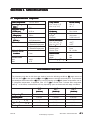
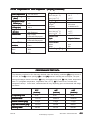
SECTION 6. SPECIFICATIONS ................................................................. 6-1
I N D E X.......................................................................................................
21' DISPENSER/NON DISPENSER ....................................................................
23'/25' DISPENSER/NON DISPENSER ................................................................
21' NON DISPENSER (MAYTAG) ......................................................................
23'/25' DISPENSER/NON DISPENSER (MAYTAG) ..................................................
23'/25' DISPENSER/NON DISPENSER (MAYTAG PREMIUM) ....................................
6-1
6-2
6-3
6-4
6-5
6-6
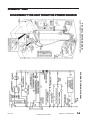
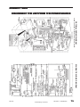
SECTION 7. SCHEMATICS ...................................................................... 7-1
INDEX ........................................................................................................ 7-1
Appendix A
Climate Zone Technology.........................................................................A-1
16010154
©2003 Maytag Corporation
CONTENTS
vi
16010154
©2003 Maytag Corporation
CONTENTS
vii
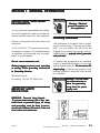
SECTION 1. GENERAL INFORMATION
INSTRUCTIONS - ELECTRICAL
REQUIREMENTS
It is the personal responsibility and obligation of the appliance owner to provide adequate electrical service for this appliance.
Observe all electrical and local codes and
ordinaces.
A 120 volt 60 Hz, 15 ampere fused electrical supply is required. An individual branch
(or separate circuit serving only this appliance) is recommended.
Do not use an extension cord.
Before plugging in power cord, operating
or testing, follow grounding instructions
in Grounding Section.
Warning - Electrical
ground is required on
this appliance!
Grounding Instructions
This appliance is equipped with a power
supply cord having a 3-prong grounding
plug. For your safety, this cord must be
plugged into a mating 3-prong type wall receptacle which is properly wired, grounded
and polarized.
If a mating wall receptacle is not available
contact a qualified electrician to have the
wall receptacle replaced. Do not use an AC
adapter plug. If there is any question, local
building officials or electrical utility should
be consulted.
Electrical Service
Grounding: 120 VOLTS, 60Hz Only
Warning - Do not under
any circumstances remove the grounding
prong from the power
supply cord.
IMPORTANT SAFETY
PRECAUTIONS
WARNING: Personal Injury Hazard To prevent unnecessary risk of fire, electrical shock or personal injury, all wiring
and grounding must be done in accordance with National Electrical Code and
local codes and ordinances.
16010154
© 2003 Maytag Corporation
SECTION 1. GENERAL INFORMATION
1-1
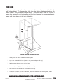
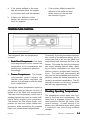
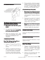
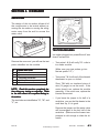
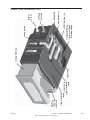
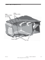
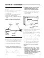
FREEZER SIDE VIEW
FORCED AIR SYSTEMS
On all forced air models, an air circulating
fan draws air from across the evaporator and
directs it to the fresh food and freezer compartments. A carefully measured amount
of chilled air is directed into the fresh food
compartment through a baffle to maintain
the desired fresh food compartment temperature. The greater part of chilled air is
directed into the freezer compartment to
maintain freezer temperature. Forced air
models use a fan cooled condenser. Depending on the model, the evaporator is
automatically defrosted every eight hours
of compressor run time. Defrosting is accomplished by a defrost heater activated by
a timer. The accumulated moisture is
drained into a defrost pan located in the
compressor area of the cabinet.
FRONT VIEW
AIR FLOW - FORCED AIR SYSTEMS
The airflow balance between the fresh food
and freezer compartments is an important
factor in maintaining proper compartment
temperatures in a forced air refrigeration
system. A baffle is used to regulate the
amount of chilled air directed into the fresh
food compartment. If a colder freezer compartment temperature is desired, the baffle
is adjusted so that less air is directed into
the fresh food compartment. This causes
the compressor to run longer since the thermostat sensing element is located in the
fresh food compartment. Cold air is drawn
across the evaporator and into the fan. A
portion of the air is deflected into the fresh
food compartment where it absorbs heat
and returns to the fin and tube evaporator
16010154
© 2003 Maytag Corporation
SECTION 1. GENERAL INFORMATION
1-2
through the return opening in the divider.
However, most of the air moving across the
evaporator is blown through the freezer air
tunnel and circulated throughout the freezer
compartment. It then circulates back across
the fin and tube evaporator where it begins
another cycle.
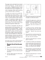
CHECKING OPERATION
The following general information explains
several methods for checking operation of
the refrigeration system. This information
applies to all systems covered in this
manual. The correct operation of a refrigeration system is dependent upon the
proper function of each of the parts comprising the system.
overload. Because some models can hold
the entire charge in the condenser, the compressor may run continuously and a definite vacuum will be noticed in the low side.
When moisture freeze-up causes a restriction, it usually occurs at the outlet end of
the capillary tube. Normally, frost buildup
can be detected in this area.
NOTE: When using a heat gun or hair
dryer, use low heat. Never use a torch.
At the discharge end of the capillary, apply
heat. If there is enough head pressure, and
if the restriction is caused by moisture
freeze-up, you will be able to hear a gurgling
noise as the heat releases the refrigerant
through the tubing.
If the system does not operate properly
(long run periods, warmer than normal temperatures), the trouble may be caused by
one of the following conditions:
It is possible that this moisture will be absorbed by the drier and remedy the trouble.
However, if the freeze-up reoccurs, you
must replace the drier.
(1) - Restricted Capillary Tube
A kink in the capillary tube will reveal the
same symptom as a moisture freeze-up,
except for the accumulation of frost. Where
possible, check the capillary tube and
straighten any kinks to relieve the restrictions. Check the unit operation. If the condition persists, replace the defective part.
If the freeze-up condition does not exist and
there is not a kink, you can assume that a
foreign particle is causing the restrictions.
The only remedy in this case is to replace
the restricted part.
The opening of a capillary tube is about the
same diameter as the period at the end of
this sentence. Because of this, it is easy to
restrict the tube. Extra precautions should
be taken when any service procedure involves moving or touching the capillary
tube. The slightest kink can cause a complete tube restriction.
Restrictions of the capillary tube may be
caused by: (1) moisture freeze-up, (2) foreign particles lodged in the tube, or (3) a
bend or kink.
If the capillary tube is restricted, there will
be a noticeable lack of frost on all cooling
surfaces; the compressor may operate for
a short period of time and cycle on the
16010154
(2) - Partial Restriction In Low Side
Tubing
Bent tubing, foreign matter, or moisture in
the system may cause a partial restriction
in the low side tubing. This is usually indicated by frost-free tubing between the re-
© 2003 Maytag Corporation
SECTION 1. GENERAL INFORMATION
1-3
striction and the capillary tube and by frostcovered tubing between the restriction and
the suction line. The restriction acts like a
second capillary tube, increasing the pressure ahead of it (warming) and decreasing
the pressure beyond it (cooling). To confirm the existence of a restriction in the low
side tubing, perform operational pressure
checks.
(3) - Slow Leak In System
On forced air models, long run time will be
noticed during the early stages of a leak. As
the refrigerant continues to escape, both
compartments will gradually warm up and
the compressor will run continuously. The
freezer will probably warm up first.
4) - Incorrect Refrigerant Charge
The sealed unit may have too much refrigerant (overcharged system) or too little refrigerant (undercharged system). The paragraphs below will inform you on how to
recognize a system with these defects.
An overcharged system may have a frost
back condition appearing on the suction
line. When the compressor stops, the frost
melts and drips on the floor. A heat exchanger separation will also cause this
symptom.
TOOLS NEEDED FOR R134A
SEALED SYSTEM REPAIR
The following list may help identify basic
refrigeration tools needed:
•
ALL HOSES AND EQUIPMENT MUST
MEET STANDARDS FOR HANDLING R134A REFRIGERANTS
•
APPROVED AND CERTIFIED RECOVERY EQUIPMENT AND RECOVERY CYLINDER (see local supplier for variety of equipment)
•
MANIFOLD GAUGE SET / HOSES MUST HAVE
LOW LOSS FITTINGS
(Robinair 41365)
•
HEATED CHARGING CYLINDER WITH R134A
SCALE (Robinair 43134B)
•
TEMPORARY ACCESS VALVES (2)
(Robinair 40288)
•
1/4" FLARE TEE - MFL X MFL X FFL
(Robinair 40399)
•
1/4" QUICK COUPLER VALVE
(Robinair 40380)
•
PROCESS TUBE ADAPTER SET
(Robinair 12458)
Other tools required, but not necessarily
dedicated to R134A Service:
•
TUBING CUTTER
(Robinair 14987A)
An undercharged system, depending on the
degree of undercharge, will operate with
temperatures above normal and the compressor run time will be increased. The
greater the undercharge, the higher the temperature will be and the longer the run time.
•
BRAZING TORCH
(Robinair 12587)
•
SWAGGING TOOLS
(Robinair 14313)
•
VOLT-WATT METER (MAYTAG CUSTOMER
SERVICE 20000019)
An undercharged system must be purged,
evacuated, and recharged with the proper
amount of refrigerant. Before recharging,
test for refrigerant leaks.
•
LEAK DETECTION EQUIPMENT FOR CFC/HCFC
AND HFC OR EQUIVALENT
•
PINCH-OFF TOOLS
(Robinair 12294 or 12396)
16010154
© 2003 Maytag Corporation
SECTION 1. GENERAL INFORMATION
1-4
NOTE: Robinair equipment is listed as a
reference only, equivalent substitutes may
be used. Additional tools may be required
for special situations.
LEAK DETECTOR - Leak detectors compatible with R134A should be used. Due to the
possibility of contaminating the sealed system with moisture, using soap bubbles can
cause problems, especially if drawn into a
low side leak. To minimize the possibility
of moisture entering the system, the use of
wet rags or towels to cool a brazed joint
should be avoided.
DRIERS/FILTERS - Any time a sealed system repair is made, the drier must be replaced. The drier on R134A systems is different, using a new desiccant which provides system compatibility and proper
moisture absorption. Use of the old type
drier on new R134A systems would result
in a repeat sealed system failure. Part number 13900-1 is the drier which must be used
on R134A systems. This drier may also be
used on R12 systems and will supersede
the 13900 drier, but be sure that the older
13900 is NOT used on the R134A system.
Additionally, "unsoldering" a joint, rather
than the score and break method, is not acceptable due to the possibility of chemical
and moisture contamination. Always cut the
drier out of the system-never apply heat.
ADDITIONAL SYSTEM
INFORMATION
CAUTION
Always wear eye protection and
protective clothing when handling
any refrigerants.
LIMIT TIME OF EXPOSURE TO THE
ATMOSPHERE - Whenever a sealed system is repaired, do not expose an open line
to the atmosphere for more than 15 minutes. Replacement components will come
sealed by either brazing (drier) or plugs
(compressor). Do not open the new drier
to the atmosphere until you are ready to
braze it into place. Before installing a new
compressor, pull a plug to be sure the unit
is still pressurized. If no pressure exists, do
not use the compressor. If pressure exists,
reinstall the plug to ensure non-contamination during the service procedure.
LOW SIDE LEAKS - In the event of a low
side leak, moisture has probably been
drawn into the system. The compressor
must be replaced in addition to the normal
repair. Also, a system flush must be made
before proceeding with the sweep charge
and final charge.
PLUGGED CAPILLARY TUBE - Moisture or
other contaminants in the R134A system can
cause the formation of gel-like or salt-type
deposits within the system. This causes
capillary tube restrictions which may not be
removed by the flush procedure detailed
later. If the restriction cannot be removed
from the capillary tube, the heat exchanger,
evaporator and compressor must be
replaced.
16010154
© 2003 Maytag Corporation
SECTION 1. GENERAL INFORMATION
1-5
SYSTEM FLUSH - Flushing of the system
is required whenever there has been a low
side leak, plugged capillary tube or compressor replacement. This is a procedure
in which R134A refrigerant is flushed
through the system and into the recovery
system to remove moisture and noncondensables which may have entered the
open system. The compressor must be
isolated during the flush procedure, in order to prevent contaminants from being absorbed into the ester oil, resulting in a contaminated system.
The system flush procedure will be done
in two parts. First, the condenser, including
the yoder loop, will be isolated by means
of process tube adapters and flushed with
4 ounces of R134A. After the drier has been
replaced, the entire sealed system, minus
the compressor, will also be flushed with 4
ounces of the refrigerant. This second step
can take about 15 minutes in order to circulate the refrigerant through the condenser,
the drier, the capillary tube, the evaporator
and out the suction line into the recovery
equipment. During this 15 minutes, the old
compressor can be removed and the replacement set into place, mounted and prepared electrically. The compressor is totally installed except for the final brazing of
the suction and discharge lines.
16010154
© 2003 Maytag Corporation
SECTION 1. GENERAL INFORMATION
1-6
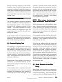
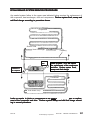
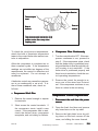
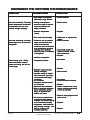
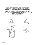
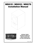
R134A SEALED SYSTEM SERVICE PROCEDURE
Any sealed system failure in the upper area indicated below requires the replacement of
the evaporator, heat exchanger, drier and compressor. Perform system flush, sweep and
add final charge according to procedure shown.
Evaporator
Suction Line
Heat Exchanger
Capillary
Process
Stub
Suction Line
Connection at
the compressor
1
Leaks at joints 1 or 2 will require
the replacement of the compressor
and drier. Perform system flush,
sweep and final charge.
2
Condenser
Drier
Yoder Heater Loop
Leaks or repairs to joints or components in the lower area require repair or replacement of the component and drier. Perform system sweep and add final charge according to normal procedure.
16010154
© 2003 Maytag Corporation
SECTION 1. GENERAL INFORMATION
1-7
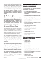
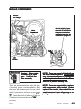
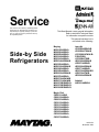
REFRIGERATION SYSTEM
All refrigerators cool by removing heat
from the cabinet rather than pumping in cool
air. In a conventional refrigerator, liquid refrigerant enters the evaporator and vaporizes (boils) due to the low pressure, creating a very cold surface which removes heat
from inside the cabinet. This causes the refrigerant to boil (evaporate) into a vapor
state and be drawn into the compressor.
The compressor pressurizes the vapor and
pumps it into the condenser. The hot vapor in the condenser gives off the heat into
the room. As the vapor cools, it condenses
back into a liquid and returns to the evaporator to start the process over again. The
system continually soaks up the heat inside
the refrigerator and deposits the heat back
into the room.
•
The compressor of the refrigeration system serves two purposes: it ensures
movement of the refrigerant throughout
the system and it increases the pressure
and temperature of the vapor received
from the suction line and pumps the refrigerant into the discharge line. The
condenser receives this high temperature, high pressure refrigerant and allows the heat to be released into the
cooler surroundings. This heat removal
"condenses" the refrigerant vapor into a
liquid.
•
The yoder loop is the last pass of the
condenser routed around the cabinet of
the freezer to help prevent moisture formation.
•
The drier is installed at the end of the
condenser or yoder loop to capture
moisture which may be present in the
system.
16010154
•
The capillary tube meters the flow of
refrigerant and creates a pressure drop.
Size and length of the capillary is critical
to the efficiency of the system.
•
As the refrigerant leaves the capillary
tube and enters the larger tubing of the
evaporator
evaporator, the sudden increase in tubing diameter, and the pumping action of
the compressor, form a low pressure
area. The temperature of the refrigerant drops rapidly as it changes to a mixture of liquid and vapor. In the process
of passing through the evaporator, the
refrigerant absorbs heat from the storage area and is gradually changed from
a liquid and vapor mixture (saturated
refrigerant) into a vapor.
•
The suction line returns this low pressure vapor from the evaporator back to
the compressor, and the cycle starts
again.
•
Part of the capillary tube is soldered to
the suction line which forms a heat
exchanger. Heat from the capillary tube
is thus transferred to the suction line to
superheat the refrigerant there and at the
same time this further cools the liquid
in the capillary tube. This cools the refrigerant before it enters the evaporator
and also heats the refrigerant before it
enters the compressor to ensure a vapor state.
© 2003 Maytag Corporation
SECTION 1. GENERAL INFORMATION
1-8
REFRIGERATION SYSTEM
16010154
© 2003 Maytag Corporation
SECTION 1. GENERAL INFORMATION
1-9
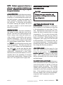
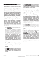
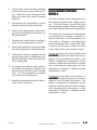
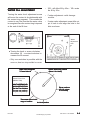
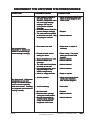
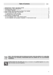
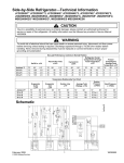
DIAGNOSIS
Sealed system diagnosis of R134A refrigerant systems is to be performed identically
to that of R12 systems. In fact, as shown in
the following flow chart, the service procedures are virtually the same, except for low
side leaks, plugged capillary tube or compressor failure which results in a system
flush.
REFRIGERATOR DIAGNOSIS
SEALED SYSTEM
IDENTIFY REFRIGERANT
R12
R134a
RECOVER
RECOVER
REPAIR
REPAIR
SWEEP
FINAL CHARGE
LOW SIDE LEAK,
PLUGGED CAPILLARY
TUBE, COMPRESSOR
REPLACEMENT?
NO
YES
LISTEN:
• What is the customer complaint?
• Are the fans operating?
• Is the compressor operating?
LOOK:
• Are ice cubes present?
• Is the light on/off when the switch is
operated?
• Are the controls set properly?
• Do door gaskets seal properly?
• Is there an ice buildup on the
evaporator cover?
• Are the return air ducts free of ice?
TOUCH:
• Is the evaporator cover warm?
• Is air felt exhausting from the kick
plate?
• Is air circulating in the freezer and
fresh food compartments?
• Is the quarter inch discharge line
from the compressor hot?
• Is the condenser warm?
SEALED SYSTEM DIAGNOSIS
FLUSH*
SWEEP
FINAL CHARGE
* FLUSH INCLUDES COMPRESSOR
REPLACEMENT
Remember, before entering the sealed system, all other systems must be tested and
properly repaired. These include the electrical system, defrost system, control operation, and air flow systems: evaporator
and condenser motors. Before "turning a
screwdriver", many checks can be made
simply by using your senses:
16010154
Once it has been determined that the other
refrigerator systems are working properly,
a probable sealed system problem can be
confirmed through the use of a wattmeter
and checks of low and high side pressures.
Access valves are not to be left on a sealed
system after service. To measure low side
pressure, a temporary access valve can be
installed on the compressor process tube.
To remove the valve after repair, a pinch off
tool may be used to seal the tube while the
valve is removed and the hole brazed shut.
To check high side pressure, a temporary
access valve should be installed on the discharge line. When the high side valve is in-
© 2003 Maytag Corporation
SECTION 1. GENERAL INFORMATION
1-10
stalled, the technician is committed to replacement of the drier and a sealed system
repair. Once again, this valve must be removed upon completion of repair. Make
sure the gauges which are used to check the
operating pressures are accurately calibrated. When not connected to a system,
the gauge pointer should indicate zero pressure. If necessary, turn the calibrating screw
until the pointer is at "0."
NOTE: The following situations are typical, however other factors such as gauge
placement, line voltage and ambient temperature must also be considered.
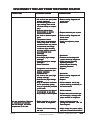
The following symptoms use high and low
side pressures plus wattage measurements
to diagnose sealed system problems. Normal low side pressure will range from below zero to about six pounds of pressure,
depending on several factors such as refrigerator model, ambient temperature, load
and customer usage. Normal high side
pressure is also dependent on external factors but will range in the 100 to 125 p.s.i.g.
range. Wattage and pressure figures will
vary based on the model and age of the refrigerator. Refer to the performance data
table(s) at the end of the manual.
-
Near normal pressure
Slightly lower pressure
Lower than normal
Diagnosis - Low side restriction. The
evaporator, suction line or other low side
tubing is probably restricted (kinked or
blocked with a foreign article such as moisture or contaminant). This condition is usually accompanied with a frost build up on
the low side of the restriction. High side
pressure will take longer to balance with the
low side pressure when the compressor is
stopped.
16010154
High Side Low Side Wattage
-
Lower than normal
Slightly lower than normal
Lower than normal
Diagnosis - High side leak. Both high and
low side pressures will drop as more refrigerant escapes.
Symptoms
Symptoms::
High Side Low Side Wattage
-
Higher than normal
Slightly lower than normal
Higher than normal
Diagnosis - Low side leak. High side pressure will continually increase since air is
being drawn into the system through the
leak and becomes trapped in the high side
tubing. The low side may show a slight increase in pressure because of the air being
drawn in through the leak.
Symptoms
Symptoms::
High Side
Low Side
Wattage
-
Lower than normal
In a vacuum
Lower than normal
Diagnosis - Capillary tube restriction. High
side pressure will take much longer (or not
at all) to equalize with the low side pressure
when the compressor is stopped.
Symptoms
Symptoms::
Symptoms
Symptoms::
High Side
Low Side
Wattage
Symptoms
Symptoms::
High Side Low Side Wattage
-
Higher than normal
Higher than normal
Higher than normal
Diagnosis - Overcharged system. The
extent of the pressure increase depends on
the amount of overcharge and ambient temperature. An overcharge may also cause the
suction line to be frosted during the run
cycle, resulting in water on the floor after
cycling off.
© 2003 Maytag Corporation
SECTION 1. GENERAL INFORMATION
1-11
Symptoms
Symptoms::
High Side
Low Side
Wattage
-
LEAK TESTING
Lower than normal
Higher than normal
Lower than normal
Diagnosis - Inefficient compressor. Cooling surfaces may be covered with a thin film
of frost, but the temperature will not descend to cut off temperature of the control,
even with continuous running. Also, the
condenser will be noticeably cooler to the
touch than normal. Once the confirmation
that an inefficient compressor is made, the
compressor should be replaced.
Symptoms
Symptoms::
High Side Low Side -
Wattage
-
Normal
Normal to slightly
higher than normal suction line possibly
sweats
Normal
Diagnosis - Separated capillary tube. The
capillary tube must be connected to the suction line to provide proper heat transfer.
Without this transfer, liquid refrigerant in the
capillary tube enters the evaporator at a
slightly higher temperature thereby lessening the ability to remove heat from inside
the refrigerator. The customer complaint
would be long run time, slow ice production, warmer fresh food temperature, in
general, poor overall performance. Another
symptom of a separated capillary tube
could be moisture on the floor behind the
refrigerator. The heat from the capillary tube
is utilized by the suction line to ensure that
vapor rather than liquid refrigerant is returned to the compressor. If liquid is
present in the suction line, frost or moisture
forms on the outside of the line and eventually drips to the floor.
16010154
Once it has been determined through
proper diagnosis that a leak is present in the
sealed system, attempt to find the leak before opening the system if possible. To
check the high side for leaks, be sure that
the compressor is running. During run time
the high side pressure is greater. To increase
the pressure slightly, stop the condenser
fan blade or block the air flow through the
condenser. To check the low side for leaks,
stop the compressor. During off times, the
low side pressure will increase to equalize
with the high side. By warming the evaporator, this pressure will increase. If too much
refrigerant has leaked out to create enough
pressure to locate the leak, add 4 ounces of
the proper refrigerant to the system and
proceed with the test procedure.
The presence of oil around a tubing joint
usually indicates a leak. Care must still be
taken to pinpoint the exact location. Remember that a leak detector compatible
with R134A refrigerant must be used. A
sealed system component, such as the
evaporator or yoder loop, should not be
condemned unless a non-repairable leak is
confirmed. This should be determined by
either locating the actual leak or by isolating the component from the rest of the system and determining if it holds pressurization or a vacuum - whichever method is
chosen.
© 2003 Maytag Corporation
SECTION 1. GENERAL INFORMATION
1-12
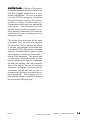
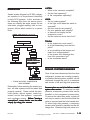
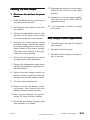
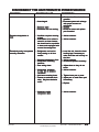
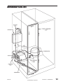
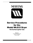
COMPONENTS
Drier
Whenever the sealed system is entered, the
drier must be replaced. For R134A refrigerant systems, use a 13900-1 drier. This
drier has the proper desiccant suitable for
the refrigerant. The drier is stamped with
an arrow which indicates the direction of refrigerant flow. The drier inlet has two lines one connects to the yoder loop and the
other will be used as a process tube through
which the system sweep and final charge
will be made. The drier outlet will be connected to the capillary tube. Care should
be taken to ensure that the capillary is not
inserted too far into the drier to make contact with its internal screen, yet in far enough
to prevent restricting the small diameter
capillary tube opening with the solder alloy.
SUCTION
LINE
YODER
CONDENSER
LOOP
EVAPORATOR
HEAT EXCHANGER
COMPRESSOR
Condenser
DRIER
The condenser is a long folded tube which
receives the hot, high pressure vapor from
the compressor. While the most common
problem is keeping the condenser clean
from lint and dirt buildup which prevents
proper airflow and the required transfer of
the heat to the surroundings, it is possible
that due to an unrepairable leak or a nonremovable restriction, the condenser could
require replacement. As with any R134A
sealed system repair, the key to success is
the limiting of the time of atmospheric exposure. Do not remove the plugs on the
condenser inlet and outlet tubes until the
new condenser is mounted in place and
made ready for brazing. The inlet side will
connect to the compressor discharge line
and the outlet to the yoder loop.
16010154
DISCHARGE
TUBE
CAPILLARY
TUBE
CONDENSER
© 2003 Maytag Corporation
SECTION 1. GENERAL INFORMATION
1-13
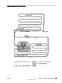
Yoder Loop
The yoder loop is a non-replaceable component of the sealed system routed within the
walls of the cabinet. To diagnose the yoder loop, the tubing must be isolated from the
sealed system. This procedure is shown below. If the loop fails to hold the vacuum, a
heater repair assembly is to be installed and the loop bypassed by connecting the condenser outlet tube directly to the inlet of the drier.
Yoder
Condenser
Loop
YODER LOOP DIAGNOSTIC TEST
1. Isolate yoder loop from remainder of sealed system.
2. Cap or seal one end of the loop (braze or use process adaptor and cap).
3. Attach process adaptor to open end of loop.
4. Attach compound gauge and vacuum pump to the loop.
5. Pull a vacuum and close valve to test for leak in the loop.
6. If unit holds a vacuum, no leak is indicated. Reconnect the yoder loop to the system, replace
the drier and recharge the system to specifications.
A VACUUM WILL BE MAINTAINED IF THE SYSTEM IS GOOD.
16010154
© 2003 Maytag Corporation
SECTION 1. GENERAL INFORMATION
1-14
Evaporator
Compressor
The evaporator is a long aluminum tube
folded or coiled within the freezer compartment. If a leak is present in the evaporator,
it is not repairable and must be replaced.
On R134A systems, whenever the evaporator is replaced, the heat exchanger must
also be replaced as well as the compressor. The replacement evaporator will come
with the heat exchanger attached. Leave the
caps in place on the opposite end of the heat
exchanger. Again, whenever the evaporator and heat exchanger are replaced on
R134A units, the compressor must also be
replaced and the sealed system flushed. Do
not connect the suction line to the replacement compressor until the system has been
flushed (see System Flush Procedure) .
After mounting the evaporator in place, connect the capillary tube of the heat exchanger
to the replacement drier.
The compressor is the "heart" of the refrigerator, consisting of an electrical motor and
a "pump" sealed inside a steel case. The
compressor used on R134A refrigerant systems is virtually the same in external appearance as the compressor used with R12
refrigerants. However, due to changes in
lubricants and other internal differences, the
compressors are not to be interchanged,
otherwise system failure will result. Diagnostic procedures will be the same as with
the R12 refrigerant systems, except that the
high side pressure will be slightly higher and
the low side pressure will be slightly lower.
If a new compressor is to be installed, pull
one of the plugs to ensure that it is properly pressurized. If no pressure is observed,
do not use the compressor. If unit is pressurized, reinstall the plug and keep the compressor sealed until it is installed and ready
for solder connections. Whenever the compressor is replaced on a R134A refrigerator, the sealed system must be flushed (see
System Flush Procedure).
Heat Exchanger
The heat exchanger is composed of the capillary tube and suction line soldered together. The heat exchanger should be replaced if there is a non-repairable leak,
plugged capillary, more than 3 inches have
been removed from the capillary or the capillary tube separates from the suction line.
If the heat exchanger is replaced, the evaporator must also be replaced as well as the
compressor.
16010154
SYSTEM FLUSH
Before accessing the sealed system, it is
necessary to determine that the problem
is actually a sealed system problem by
utilizing a wattmeter, thermometer, visual
and touch indicators. Once it has been
determined that the problem is in the
sealed system, and diagnosis indicates a
low side leak, plugged capillary tube, or a
defective compressor, in addition to the
normal repair, the system must be flushed
and the compressor must be replaced.
© 2003 Maytag Corporation
SECTION 1. GENERAL INFORMATION
1-15
SEALED SYSTEM REPAIR
SUMMARY
A.
Recover the refrigerant in the
system, if any.
B.
Repair the low side leak or replace
the evaporator and heat exchanger,
whichever applies. If the complete
low side is replaced, do not braze
the suction line to the replacement
compressor until the completion of
Step 3 of System Flush Procedure.
C.
Proceed with the following flush
procedure which includes the
compressor replacement.
D.
After flushing procedure is completed, continue with the normal
sweep and final charging procedure.
Next, score and break the tube at the yoder
loop to the input side of the drier. Attach a
process tube adapter to the condenser side
of this break. Connect a quick coupler hand
valve to this process adapter. Connect the
hose from the recovery equipment to this
valve (figure 1). Use the heater on the charging cylinder to ensure the cylinder pressure
to be approximately 30 pounds above
room ambient temperature. For example,
if room temperature is 70 degrees, cylinder pressure should be 100 p.s.i.g. Start the
recovery system and open the valve at the
process adapter attached to yoder loop.
Open the valve from the charging cylinder
and allow 4 ounces of R134A to flow through
the condenser and into the recovery system. This process should take about two
minutes. Keep the process adapters and
hoses attached at this time.
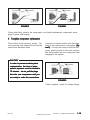
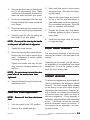
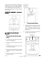
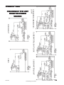
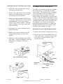
SYSTEM FLUSH PROCEDURE
1. Isolate and flush the Condenser
Score and break the discharge line at a convenient location to which the replacement
compressor tubing can be connected later.
Attach a process tube adapter to the condenser side of this break. Connect a quick
coupler hand valve to the process adapter.
Connect the hose from the charging cylinder to this valve (refer to figure 1). This connection will remain in place throughout the
flush procedure in Step 3.
NOTE: Due to the extra flushing and
sweep charge procedures, about 12
ounces of R134A refrigerant should be
added to the original charge specified on
the model/serial plate and loaded into the
charging cylinder initially.
16010154
© 2003 Maytag Corporation
SECTION 1. GENERAL INFORMATION
1-16
FIGURE 2
FIGURE 1
Flush into discharge line, through hi-side
and out the yoder loop at drier inlet.
Flush the entire system (less compressor)
out the suction line.
2. Replace the Drier
3. Isolate and flush the remainder of
the system
Score and break either one of the two inlet
lines on the new drier (the other line will
remain sealed until the sweep charge, at
which time it will be the process tube). Prepare the drier outlet side for connection to
the capillary tube. The capillary tube should
be inserted about 3/4 inch into the drier to
prevent solder alloy from plugging the capillary tube or the capillary tube extending
too far into the drier and contacting the
screen. To facilitate the installation, place a
slight bend in the capillary tube about 3/4
inch from the end and insert into the drier.
Remove the process tube adapter from the
yoder outlet and prepare the tube for connection to the drier inlet. The drier inlet joint
will be the only copper-to-steel connection
which will require the silver solder and flux.
To help prevent flux from entering the system, first insert the line from the yoder loop
into the drier inlet, then apply the flux. Braze
both the inlet and the outlet joints of the replacement drier.
16010154
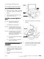
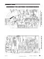
Score and break the suction line close
enough to the old compressor to be able
to reconnect it to the replacement compressor later. Attach a process tube adapter
to the evaporator side of the suction line.
Connect the hand valve and hose from the
recovery equipment to this adapter (figure
2). Be certain that the pressure in the charging cylinder is about 30 p.s.i.g. above ambient temperature. Start the recovery unit and
open the hand valve to the suction line.
Release four (4) ounces of R134a from the
charging cylinder into the system. It will take
about 15 minutes for the refrigerant to pass
through the condenser, yoder loop, drier,
capillary tube, evaporator, suction line and
into the recovery system. This 15 minutes
time can be utilized to remove the old compressor (figure 3) and prepare the new compressor by mounting into place and wiring
electrically. Remember to leave the plugs
in place until brazing (refer to
figure 4).
© 2003 Maytag Corporation
SECTION 1. GENERAL INFORMATION
1-17
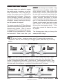
FIGURE 4
FIGURE 3
During final flush, remove old compressor, and install replacement compressor leave
plugs in place until brazing.
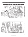
4. Complete compressor replacement
Close valves to the recovery system. Remove process tube adapters from both the
suction and discharge lines.
Connect and braze suction and discharge
lines to the replacement compressor (figure 5). You are now ready to add the temporary piercing valve to the drier process
line and proceed with the sweep and final
charging of the system.
CAUTION
In order to prevent sealed system
contamination, the time of atmospheric exposure must be limited to
15 minutes. do not pull the plugs
from the new compressor until you
are ready to make the connections.
FIGURE 5
Flush complete - ready for sweep charge.
16010154
© 2003 Maytag Corporation
SECTION 1. GENERAL INFORMATION
1-18
SWEEP AND FINAL CHARGE
The sweep charge is a method of purging
the sealed system of moisture, air and potential contaminants. Also during this procedure, the system may be checked for
leaks before the final charge. If this procedure is followed as outlined, it will allow for
the capture of 90-95 percent of the available
refrigerant, thereby ensuring that the system will operate as designed.
The sweep procedure for R134a refrigerant
systems is made after the system has been
repaired and/or flushed. Three (3) ounces
of refrigerant R134a is added to the system,
circulated by the compressor for 5 minutes
and recovered. Since a new drier - part
#13900-1 has already been installed, a high
side process tube is available. Install a temporary access valve to this process tube
close enough to the end of the tube so that
the tube can be pinched closed behind the
valve and the opening sealed shut after the
valve is removed. Remember, no access
valve is to be left on the sealed system. Connect a 1/4 inch flare tee to the access valve.
Connect a quick coupler hand valve to each
side of the tee. To one hand valve, connect
the hose from the charging cylinder. To the
other valve, connect the hose to the recovery system.
The following steps take you through the
sweep and final charge.
•Step 1. Set up of valves: temporary access valve (C) piercing drier process tube,
connected to flare tee, hand valve (A) to charging cylinder, hand valve (B) to recovery
system.
ACCESS VALVE
TO
CHARGING
CYLINDER
A
C
B
TO
RECOVERY
SYSTEM
•Step 2.
2 With liquid refrigerant present to valve A, valve B closed and valve C open
(C will remain open throughout sweep procedure), open valve A to allow three (3)
ounces of refrigerant into the system. Close valve A. Check low side for leaks. After
system has equalized (about 3 to 5 minutes), start system compressor, check for high
side leaks and allow refrigerant to circulate in the system about 5 minutes.
ACCESS VALVE
TO
CHARGING
CYLINDER
16010154
A
C
© 2003 Maytag Corporation
B
TO
RECOVERY
SYSTEM
SECTION 1. GENERAL INFORMATION
1-19
•Step 3. Leave valve A closed and valve C open. System compressor still running,
open valve B to allow refrigerant to flow into the recovery system. After vacuum
has been held, turn off system compressor.
ACCESS VALVE
TO
CHARGING
CYLINDER
A
C
B
TO
RECOVERY
SYSTEM
•Step 4. Close valve B. Liquid refrigerant still present to valve A and charging cylinder
pressure is 30 p.s.i.g. above room ambient. Open valve A to slowly allow the proper
refrigerant charge into the system. Close valve A. If needed, valve C can be closed
and valves A and B opened to recover refrigerant in the hoses and charging cylinder.
ACCESS VALVE
TO
CHARGING
CYLINDER
A
C
B
TO
RECOVERY
SYSTEM
•Step 5. Use pinch-off tool to seal the process tube between the drier and the access
valve. Remove the access valve and braze the opening. After the required five minute
equalization time, start the system compressor.
16010154
© 2003 Maytag Corporation
SECTION 1. GENERAL INFORMATION
1-20
SECTION 2. COMPONENTS
COMPRESSOR REPLACEMENT
The following general information explains
how to successfully replace compressors
for any model covered in this manual.
All replacement compressors are charged
with the correct amount of oil and a holding
charge of dry nitrogen.
The holding charge is your assurance that
the compressor is dry and ready to install.
If you receive a replacement compressor
that shows no evidence of holding charge
when you center the lines or remove the
plugs, return it.
NOTE: A new drier must be installed each
time any component of the system is
opened or replaced.
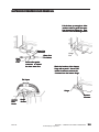
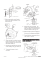
REPLACING THE COMPRESSOR
1.
2.
Cut
Here
Cut
Here
Disconnect the unit from the power
source.
Locate defective compressor and
evacuate the sealed system.. (See
Sweep Charging and Refrigerant
Recovery.)
Cut
Here
3. Clean and cut the refrigerant lines as
close as possible to the compressor
stubs, leaving enough length to install
the replacement compressor.
16010154
© 2003 Maytag Corporation
SECTION 2. COMPONENTS
2-1
4.
Disconnect lead wires from compressor terminals.
5.
Remove the retaining clips from the
compressor mounts. Remove defective compressor from cabinet and install rubber grommets on replacement
compressor.
6.
Clean the compressor stubs with an
abrasive cloth such as grit cloth No. 23.
Do not open the compressor stubs.
7.
Install the replacement compressor using the mounting clips previously removed.
8.
Connect the compressor leads.
9.
Solder a short piece of tubing to the process tube (approximately 6 inches
long). Connect the refrigerant tubing
to the compressor stubs using silfos on
copper to copper joints and silver solder and flux on steel to copper joints.
Locate and remove old drier. Install new
drier. The new driver is installed in the following manner:
a.
Carefully bend the old drier and tubing
away from electrical parts.
b.
Use steel wool or fine emery paper to
clean the capillary tube 3 inches from
the original joint. Also, clean the input
tubing to the drier of 3 inches from the
original joint.
c.
Use steel wool or fine emery paper to
clean both ends of the new drier. Use a
knife or file to score the capillary tube 1
inch from the original joint. Use your
finger to break the connection.
d.
Make an offset 1/2" from the end of the
cap tube to prevent it from penetrating
too far into the drier.
16010154
e.
Cut the inlet tube of the replacement
drier and use pliers to snap off the
scored end.
f.
Install the new drier using silver solder
with the proper flux at the Yoder tube
to drier joint. Use silfos at the drier to
capillary tube joint.
10. Evacuate, recharge and leak test the
system.
11. Test run the unit to check operation
12. Replace the machine compartment
cover.
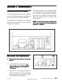
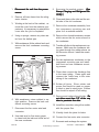
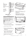
CONDENSER REPLACEMENT
The following general information explains
how to successfully replace the condenser
for any model covered in this manual.
© 2003 Maytag Corporation
SECTION 2. COMPONENTS
2-2
9.
Evacuate the sealed system. (See
Sweep Charging and Refrigerant Recovery.)
1.
Disconnect the unit from the power
source.
2.
Remove all loose items from the refrigerator interior.
3.
Working at the back of the cabinet, remove the cover from the machine compartment. It is necessary to reinstall this
cover after the job is completed.
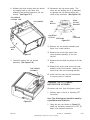
11. Remove the condenser assembly from
the compressor mounting pan and
place it on a workable surface.
4.
Using a sponge, remove any drain water from the defrost pan.
12. Remove the shroud/condenser screws
which secure the fan motor shroud to
the condenser.
5.
With assistance, tilt the cabinet back and
remove the front condenser mounting
screw.
Cut
Here
Front Condenser
Mounting
Screw
Shroud/
Cond.
Screw
10. Clean and then cut the inlet and the outlet tube of the old condenser.
13. Transfer all clips to the replacement condenser. Make sure the condenser tubing goes through the rubber sleeve on
the fan motor shroud. Install the mounting screws.
14. Set the replacement condenser on the
compressor mounting pan and install
both front and rear condenser mounting screws.
15. Clean then connect the discharge line
to the inner tubing. Clean again and
connect the Yoder loop to the outer
tubing of the condenser.
Cut
Here
Condenser
Mounting
Screw
6. With assistance, return cabinet to upright position. Remove the back condenser mounting screw.
7. Disconnect the fan motor wire lead
connector.
8. Use steel wool or fine emery paper
to clean both the inlet and outlet end of
the new condenser.
16010154
16. Solder all joints. Silver solder and
proper flux should be used on copper
to steel or steel to steel joints. Excess
flux should be wiped off all tubing.
17. Remove and replace the old drier. Do
not allow more than 1/2" of the cap
tube to penetrate the drier.
18. Install the new drier using silver solder
with the proper flux.
19. Visually check the joints for leaks.
20. Connect the fan motor wire connector.
21. Evacuate and recharge the system.
© 2003 Maytag Corporation
SECTION 2. COMPONENTS
2-3
22. Test for leaks.
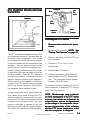
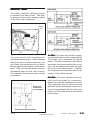
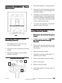
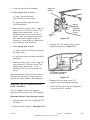
Testing the Compressor Direct
23. Install the machine compartment cover.
24. Test run the refrigerator to make sure
it is operating properly.
ELECTRICAL SYSTEM
•
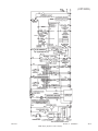
The wiring diagram is located in the control housing area.
Testing the compressor with no other wiring in the circuit is called the direct test
method. Remove all electrical components
from the compressor in order to perform
this test. It is recommended that a compressor tester as illustrated be used to
make this test.
Common
•
All electrical components are grounded
to the cabinet.
•
The green/yellow center conductor in
the power cord is attached to the cabinet to provide a ground circuit when the
cord is plugged into a properly
grounded outlet.
•
After replacing an electrical component,
always reconnect the ground wire.
•
The electrical outlet should be checked
to make sure it is properly wired.
Check the outlet with a circuit tester.
COMPRESSOR TESTER
Run
Common
SWITCH
SWITCH::
Off, Run, Start
Start
Power
Plug
16010154
Start
Run
The tester leads are marked RUN, START,
and COMMON. Connect the common lead
to the common terminal of the compressor, the start lead to the start terminal and
the run lead to the run terminal. The compressor terminal arrangements are illustrated above. The other two leads are for a
start capacitor (if used). When not in use,
attach the two leads together and place the
toggle switch in the OFF position. There
should not be any bare leads touching the
cabinet. Plug in the tester and flip the switch
to the start position. When the compressor starts, release the switch to the run position. If the compressor is operative, it will
continue operating on the run windings. If
the compressor fails to run, the compressor is defective and must be replaced.
Capacitor
© 2003 Maytag Corporation
SECTION 2. COMPONENTS
2-4
Overload Protector
The overload protector prevents the compressor from burning out its electrical windings in the event the compressor becomes
overheated or draws too much current. The
overload trips, opening the circuit to the
compressor. If it does this repeatedly, the
compressor is said to be cycling on the
overload.
pressor starts, the over load is defective
and must be replaced. If the compressor
fails to start, check for a defective start relay or compressor.
1.
Remove the PTC and overload from the
compressor.
2.
Connect one ohmmeter probe to the
compressor shell. Make sure the probe
makes good contact with bare metal.
One at a time, connect the other ohmmeter probe to each of the three compressor terminals.
Cycling on the overload may be caused by:
1.
Insufficient air circulation around the
compressor and condenser.
2.
Pull-down on the compressor, caused
by a large quantity of warm food
placed in the refrigerator.
3.
Compressor stalling due to lack of pressure unloading.
4.
Low line voltage.
5.
Defective start relay.
6.
Defective winding in the compressor or
shorted windings.
3. If the meter shows no continuity to
ground, install PTC and overload protector to the compressor's terminals. If
the meter indicates the compressor terminals are grounded, replace the
compressor.
4.
Attach a jumper wire across the overload terminals.
5.
Make sure the jumper wire does not
short to ground.
6.
Reconnect the unit to power source. If
the compressor starts, the overload
protector is defective and must be replaced.
Testing the Overload Protector
Disconnect the unit from the power
source.
To test the overload protector, remove the
compressor terminal cover. Examine the
bottom of the overload for signs of arcing.
If signs of arcing are present, either check
for continuity or connect a jumper wire
across the terminals. If using a jumper wire,
plug in the line cord and set the temperature control to a cold setting. If the com-
16010154
© 2003 Maytag Corporation
SECTION 2. COMPONENTS
2-5
Common
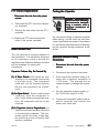
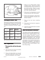
PTC STARTING DEVICE AND RUN
CAPACITOR
Run
Start
Overload
Protector
Run
Capacitor
PTC
Relay
Blue
Capacitor
Leads
Orange
Checking the PTC Device
1. Disconnect the unit from the power
source
source.
The PTC solid state starting device is a pushon component mounted to the start and run
terminals of the compressor. This device
is connected in parallel with the run capacitor and is in series with the compressor start
windings. This will produce a short circuit
across the run capacitor during the compressor starting sequence and full current
is applied to the start windings as well as
the main winding. Since the PTC device is
temperature sensitive, a variance in its temperature causes a change in its resistance.
When current is first applied to the compressor, the PTC device's low resistance
shorts out the run capacitor; thus producing adequate motor starting torque.
As the compressor motor approaches running speed, the current through the PTC
device causes the temperature and resistance of the PTC device to increase to where
it appears to be an open circuit. The compressor continues to operate on the run
winding in parallel with the series combination of the run capacitor and start winding.
16010154
2. Discharge the capacitor. NOTE: See
"Testing The Capacitor" on page 2-7.
3.
Remove the wires from the PTC device terminals.
4.
Allow the PTC to cool to room
temperature.
5.
Remove the PTC device.
6.
Using an ohmmeter, check the resistance between the PTC device terminals. The ohmmeter should register
between 3 and 20 ohms.
An extreme variance between 3 and 20
ohms indicates a defective PTC device
which must be replaced.
NOTE: We discourage using a voltmeter
to check performance of the PTC device
because test results are influenced by
several factors, such as its dependence
on line voltage to the compressor, the response characteristic of the voltmeter
and the PTC device temperature at the
time the compressor is energized.
© 2003 Maytag Corporation
SECTION 2. COMPONENTS
2-6
PTC D
evice Replacement
Device
Testing the Capacitor
1. Disconnect the unit from the power
source.
2.
Disconnect the PTC from the compressor terminals.
3.
Remove the lead wires from the PTC
terminals.
4. Replace the PTC and reconnect the
wires to the proper terminals.
RUN CAPACITOR
The run capacitor is mounted adjacent to
the compressor. It is electrically connected
to the compressor circuit to provide the
required phase difference between the start
and run windings for running the
compressor.
Warning - Discharge a capacitor before handling.
Short across its terminals,
using a resistor with a
minimum resistance of
1,000 Ohms.
We recommend using a capacitor analyzer
when testing. A solid state unit that measures capacitance and power of any capacitor, and has an automatic means of discharging the capacitor through resistance is preferred.
Alternate Method Using
Ohmmeter
1.
Disconnect the unit from the power
source.
Capacitor Failures May Be Caused By
By:
2.
Disconnect the capacitor lead wires.
(1) A Short Circuit - Will cause the start
windings to be energized continuously
in the start mode. The compressor
could start, but the overload protector
will trip, and eventually trip continuously.
3.
Short across the terminals using a resistor with a minimum resistance of
1,000 ohms. This ensures that no
charge remains to damage the ohmmeter.
4.
Set the ohmmeter selector switch to
the 10,000 ohm scale (R x 10K).
5.
Connect the ohmmeter leads to the capacitor terminals and observe the
meter point lower end.
(2) An Open Circuit - Should, under normal
conditions, allow the compressor to
start. Under a heavy running load, however, the compressor will trip on the
overload.
(3) A Capacitor Low in Capacitance - A
capacitor may lose capacitance by a loss
of its electrolytic properties. The compressor would run under a light load,
but would trip on the overload in high
ambient conditions.
16010154
© 2003 Maytag Corporation
SECTION 2. COMPONENTS
2-7
a.
If the pointer deflects to the lower
end and remains there, the capacitor is shorted and must be replaced.
b.
If there is no deflection of the
pointer, the capacitor is open and
must be replaced.
c.
If the pointer deflects toward the
high end of the scale and then
slowly returns to the low end,
the capacitor is good.
TEMPERATURE CONTROL
The refrigerator has two temperature
controls:
1.
Fresh Food Compartment - The fresh
food temperature control senses the
temperature of its compartment and
governs the compressor operation
accordingly.
2.
Freezer Compartment - The freezer
compartment control adjusts the
damper door which regulates the
amount of air allowed to enter the fresh
food compartment.
Turning the freezer temperature control to
the coldest settings reduces the flow of
chilled air to the fresh food compartment.
The fresh food temperature control uses a
sensing element that must be cooled sufficiently before stopping the compressor.
The reduced air flow causes longer compressor run time and colder freezer temperatures, while maintaining the required
fresh food compartment temperatures.
16010154
Conversely, by turning the freezer temperature control to the warmest setting, you increase the flow of air into the fresh food
compartment and decrease the flow to the
freezer. This cools the fresh food temperature control sensing element faster, resulting in shorter compressor run times and
warmer freezer compartment temperatures. The fresh food compartment will
stay near the recommended fresh food temperature, unless the freezer temperature is
turned to an extreme temperature. The differential between cut-in/cut-out temperature will vary approximately 100F.
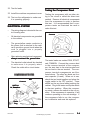
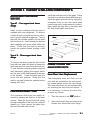
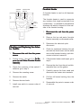
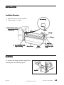
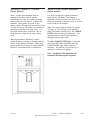
Checking Operating Temperatures
The temperature control feeler tube is located in the fresh food compartment. The
feeler tube is wrapped around a thermal
mass located in the back left corner of the
control housing. A small amount of air
passes over the thermal mass which gives
a consistent run time during ambient
changes.
© 2003 Maytag Corporation
SECTION 2. COMPONENTS
2-8
Thermal Mass Retainer
Thermocouple
Lead
Front of
Cabinet
Rear of
Cabinet
Tape thermocouple lead at the 12:00
position on the last wrap of the
capillary tube
To check the cut-in/cut-out temperatures,
attach the bulb of thermistor temperature
tester to the control feeler tube and set controls at midposition.
•
Compressor Runs Continuously
1.
Turn the control knob to OFF. If the compressor continues to run, proceed to
step 2. If the compressor stops, check
that the feeder tube is positioned properly and that the air flow through the control housing is not restricted. If the
feeler tube is positioned properly and
there is no air restriction, check the control operating temperatures.
2.
Remove the control far enough to remove one of the wires from its terminal. If the compressor continues to run,
there is a short in the unit wiring.
Allow the compressor to complete two or
three complete cycles. If the temperature
readings are not within two degrees of the
requirements the control is defective and
must be replaced. Do not attempt to
recalibrate.
A defective control may cause the compressor to run continuously or not at all. If either of these conditions exist, check as
follows:
• Compressor Won't Run
Temperature Control Replacement
1.
Remove the control enough to expose
its terminals.
2.
Short across the control terminals. If
the compressor starts, install a new
control. If the compressor fails to start,
check the defrost timer, compressor
receptacle, and unit wiring for defects.
16010154
1.
Disconnect the unit from the power
source.
2.
Open the fresh food door and remove
any loose items on the top shelf.
3.
Remove the light shield cover by pulling down on the back corners of the
cover, and sliding the cover forward.
© 2003 Maytag Corporation
SECTION 2. COMPONENTS
2-9
4.
Remove the control housing mounting
screw at the back of the control housing. Slide the control housing to the
right and lower from control housing
supports.
5.
Disconnect the temperature control
housing electrical quick disconnect.
6.
Remove the temperature control housing from the refrigerator and place on a
flat work surface.
7.
Remove the control knob by pulling it
away from the temperature control.
8.
Remove the electrical and ground leads
from the temperature control terminals.
9.
Remove the control by pushing on the
tab with right thumb to release the lock.
With the left hand, rotate the control out
of its locking tabs.
10. To remove the thermal mass, insert a
flat bladed screwdriver between the
thermal mass and the control housing
area. Turn the screwdriver to release
the mass from its locking tab.
11. Install the replacement control in the reverse order of removal.
16010154
AUTO DAMPER CONTROL
MODELS
The Auto Damper model refrigerator has
two controls and both have capillary sensing. The Auto Damper controls the fresh
food temperature and the Freezer Temperature Control guides the freezer temperature.
The fresh food compartment temperature
is maintained by a damper assembly located at the back of the temperature control housing. Changes in air temperature
cause the damper door to open and close.
A control rod and gear connect the fresh
food control knob to the damper control.
Turning the fresh food control knob to the
COLDEST position increases the flow of
freezer air into the fresh food section. The
freezer compartment temperature control
warms at a faster rate and cools at a slower
rate, increasing the compressor run time
necessary to maintain a satisfied freezer
temperature control.
Turning the fresh food control knob to a
WARMER setting decreases the flow of
chilled air into the fresh food section. The
freezer compartment temperature control
warms at a slower rate and cools at a faster
rate, decreasing the compressor run time
necessary to maintain a satisfied freezer
temperature control.
© 2003 Maytag Corporation
SECTION 2. COMPONENTS
2-10
Checking the Auto Damper
1.
Disconnect the unit from the power
source.
2.
Open the fresh food door and remove
any items on the top shelf.
3.
Set the fresh food control to the coldest position.
4.
Remove the light shield cover by pulling down on the back corners of the
cover and sliding the cover forward.
5.
Remove the fascia/radiant shield
mounting screws. Remove the control
housing mounting screw at the back,
bottom center of the control housing.
Slide the control housing to the right.
Lower the control housing.
6.
Disconnect the temperature control
housing electric quick disconnect.
7.
Remove the temperature control housing from the refrigerator and place on a
flat work surface.
8.
Remove the auto damper control rod
retainer, control rod and the slide control gear from the auto damper control.
9.
Turn the control housing over.
13. Submerge into a glass of ice (no water).
Watch for door to move to the closed
position.
14. Remove from ice and warm capillary
tube (use your hand). Watch door for
opposite reaction.
15. If no movement is detected, replace
the control.
Auto Damper Control Replacement
1.
Complete steps 1 through 10, checking
auto damper.
2.
Reinstall new auto damper.
3.
Reinstall control housing in reverse order of removal.
10. Remove the two auto damper mounting screws, then remove the auto
damper from the control housing.
11. Mark the auto damper rod approximately 1/4" away from the housing.
12. Uncoil the auto damper capillary tube
approximately four inches.
16010154
© 2003 Maytag Corporation
SECTION 2. COMPONENTS
2-11
AUTO DAMPER CONTROL - Exploded View
16010154
© 2003 Maytag Corporation
SECTION 2. COMPONENTS
2-12
DEFROST TIMER
The freezer evaporator defrosting system
is actuated by an electric timer. The timer
is mounted in the control housing located
in the fresh food compartment.
Defrost
Timer
The timer control shaft is designed for
screwdriver advancement. When manually
setting the timer to initiate defrosting, turn
the control shaft clockwise until you establish the approximate location of the defrost
cycle. Then turn the shaft slowly, and stop
immediately when the first click is heard.
The schematic illustrates the timer circuits
in sequence.
To advance
defrost timer
turn clockwise
1st Click - The timer turns off the compressor and freezer fan circuit for approximately
23 minutes, and it energizes the defrost
heater. Once the temperature of the defrost
termination thermostat reaches the cut-out
point, the termination thermostat will open
the circuit to the radiant heater. However,
the compressor circuit remains open for the
duration of the defrost interval.
2nd Click - The timer switches off the defrost circuit and starts the compressor,
freezer fan, and the condenser fan motor.
The compressor and fan motors are now
governed by the temperature control for a
period of approximately 8 hours of the compressor run time, after which a new defrost
cycle begins.
Defrost timer mounting screws
16010154
© 2003 Maytag Corporation
SECTION 2. COMPONENTS
2-13
4.
Remove the fascia/radiant shield
mounting screws. Remove the control
housing mounting screw at the back of
the control housing. Slide the control
housing to the right and lower it from
the control housing supports.
5.
Disconnect the temperature control
housing electrical quick disconnects.
6.
Remove the temperature control housing from the refrigerator and place on a
flat work surface.
7.
Remove the two timer mounting
screws.
8.
Disconnect the electrical connector
from the timer.
9.
Install the replacement timer in reverse
order of removal.
#2 Yellow
#1
White
#4 Orange
#3 Blue
Checking the Defrost Timer
Disconnect all wires from the timer and attach ohmmeter probes to the terminals
specified in the accompanying chart. If no
continuity is indicated, the timer is defective.
To Test
Turn Timer
Knob To
Check Between
Terminals
Timer Motor
Circuit
Leave as is
1&3*
Defrost
Circuit
1st Click
1&2
Compressor
Circuit
2nd Click
1&4
*See Maytag Monthly Bulletin, June 1993 volume:03 Issue 40
Page 1 Low watt Timers (This test works on all low watt timers.)
Timer Replacement
1.
Disconnect the unit from the power
source.
2.
Open the fresh food door and remove
any items on the top shelf.
3.
Remove the light shield cover by pulling down on the back corners of the
cover and sliding the cover forward.
16010154
ADAPTIVE DEFROST CONTROL
The adaptive defrost control assembly is a
microprocesser controlled defrost timer.
This new control allows defrost to occur
only when needed, compared to mechanical timers which defrost at a preset interval
whether it is necessary or not. The new
control will continually adjust defrost intervals based on the amount of time the defrost heater is energized. This allows the
defrost intervals to be adjusted closer to
the optimum defrost interval based on use,
thus saving energy.
© 2003 Maytag Corporation
SECTION 2. COMPONENTS
2-14
Checking the Adaptive Defrost
Control
1.
Disconnect the unit from the power
source.
2.
Open the fresh food door and remove
any items on the top shelf.
3.
Remove the light shield and the temperature control housing (see steps 3
and 4 replacing the timer).
4.
Connect the refrigerator to a wattmeter.
5.
Make sure compressor is running (cold
control closed).
6.
Using an insulated number 22 jumper
wire short between L1 and Test; this will
put the refrigerator into a defrost for
approximately 23 minutes.
7.
The watt meter should read between
500 to 600 watts depending on the
model.
Note: If the temperature control is open
(unit not running and you jumper L1 and
Test) the unit will cycle through the test
mode in two seconds and there will be no
watt draw.
16010154
AIR FLOW - FORCED AIR SYSTEMS
These models use a metal sheath heater to
remove accumulated frost from the freezer
evaporator and drain trough during a defrost cycle.
The defrost timer (models) energizes the
defrost heater every 8 hours of accumulated compressor run time. When the temperature in the thermostat area reaches approximately +43o F. the thermostat contacts
open the circuit to the defrost heater.
An ohmmeter check will determine if all
phases of the defrost cycle are functioning
properly. The defrost thermostat contacts
open at approximately +43o F. and close at
approximately +15o F.
The defrost thermostat has a 240K ohm resistor connected internally across the two
terminals. This resistor permits checking
the defrost heater when the evaporator temperature is +15o F. or higher.
An ohmmeter can be used to test the defrost heater and thermostat without disassembling the freezer compartment even if
the evaporator temperature is +15o F. or
higher. To check, proceed as follows:
1.
Disconnect the unit from the power
source.
2.
Open the fresh food door and remove
any items on the top shelf. Remove the
light shield and the fascia/radiant shield
mounting screws in the temperature
control housing. While holding the
front of the housing, remove the rear
mounting screw. Lower the control
housing.
© 2003 Maytag Corporation
SECTION 2. COMPONENTS
2-15
3.
Disconnect the timer wire harness connector from the defrost timer.
4.
Set the ohmmeter to R x 1K scale and
connect the probes to the No. 2 and
No. 3 terminals of the disconnect plug.
5.
The meter should read between 20 to
40 ohms. The resistance is not critical.
If there is continuity between terminals
No. 2 and 3, the defrost heater is in operative condition. If there are no resistance readings (open circuit) the defrost
heater and thermostat must be checked
individually.
NOTE: When using the meter, avoid
touching the probes as this could result
in a false reading and misdiagnosis.
To test the defrost heater and thermostat
when the evaporator temperature is +15ºF.
or below, proceed as follows:
1.
Disconnect the unit from the power
source and plug it into a watt meter
meter.
2.
Plug the watt meter into power source
and manually advance the defrost timer
to the defrost cycle. See the defrost
timer section for information on manually advancing the timer.
16010154
3.
The watt meter should read between
345 and 475 watts depending on the
model (total wattage of the timer motor and defrost heater). Should the
reading be 0 to 4.5 watts, the defrost
heater or thermostat is defective. To
further isolate the defective part, proceed to step 4.
4.
Disconnect the unit from the watt meter.
5.
Follow steps 2 and 3 of testing the
heater and thermostat when the evaporator temperature is +15ºF. or higher.
6.
If the meter reads approximately 240K
ohms, the defrost thermostat is defective.
To use an ohmmeter, set the meter to R x
1K scale. If the reading is approximately 20
to 40 ohms, the defrost heater and thermostat are operative.
© 2003 Maytag Corporation
SECTION 2. COMPONENTS
2-16
DEFROST HEATER REPLACEMENT
1.
Disconnect the unit from the power
source.
2.
Remove the ice maker if equipped.
3.
Remove the evaporator cover by loosening the top two screws on each corner of the cover and removing the bottom screws on each corner.
4.
Tilt the top of the evaporator cover forward and disconnect the wire harness
connector.
5.
Remove the evaporator cover and fan
motor assembly. It is very important
that this part be reinstalled in the same
manner as it was originally.
6.
Disconnect the defrost heater wire
leads. Using long nose pliers, remove
the defrost heater retainer clips. (One
on the right side of the heater and one
on the left side).
7.
3.
Remove the defrost thermostat and
mounting clip by releasing the mounting clip that is snapped around the
evaporator tubing.
4.
Install the new defrost thermostat in the
reverse order of removal. Make sure
the thermostat is located per the drawing below.
Defrost Thermostat
1.5" Away From
Back of the Freezer Wall
Foam Block
Install the replacement heater in the reverse order of removal.
DEFROST THERMOSTAT
REPLACEMENT
The defrost termination thermostat is located on the top right side of the
evaporator.
1.
Follow the first five steps in replacing
the defrost heater.
2.
Disconnect the leads from the
thermostat.
16010154
© 2003 Maytag Corporation
Defrost Heater
Clip
SECTION 2. COMPONENTS
2-17
CONDENSER FAN MOTOR
Remove Motor
Wire Harness
Lock Lever
Remove Ground
Wire Screw
Remove Fan
Motor Bracket
Screws (3)
The condenser fan motor is connected in
parallel with the compressor. If the compressor runs but the motor doesn't, the
motor is either defective or disconnected.
If neither operates, check the cold control,
defrost timer, and the cabinet wiring.
To Check The Condenser Motor
Direct
1.
To remove the lead connector from the
condenser fan motor, grasp the connector with your thumb inserted between the
connector and the locking lever as shown.
Pull the connector away from the motor.
4. Attach a 115v test cord to condenser
motor and plug into a power source. If
the motor fails to operate, it is defective and must be replaced.
Disconnect the unit from the power
source.
2. Remove the insulated cover from the
rear of the cabinet.
3. Disconnect the condenser fan motor
lead connector on the motor terminals.
16010154
© 2003 Maytag Corporation
SECTION 2. COMPONENTS
2-18
Loosen
the screw
Condenser Fan Motor Replacement
1.
Disconnect the unit from the power
source.
2.
Remove the insulated cover from the
rear of cabinet.
3.
Disconnect the condenser fan motor
lead connector on the motor terminals.
4.
Remove the screws that mount the fan
motor to the brackets.
5.
Transfer the fan blade to the replacement motor making sure it is installed
in the same manner as the original.
Loosen
the screw
Fan
Cover
Remove
the screw
Remove
the screw
Freezer Fan Motor Diagnosis
6.
Install the fan motor leads and ground
wire.
1.
Disconnect unit from the power
source.
7.
Install those parts previously removed.
Test run the unit.
2.
Remove the freezer shelving.
3.
Loosen the two top screws and remove
the two bottom evaporator cover
mounting screws.
4.
Grasp the bottom of the cover. Carefully pull the cover forward and down
to clear the upper flange.
5.
Disconnect the evaporator fan motor
leads. The wire leads are self-locking
and it is important to squeeze the clip
before pulling the leads off the
terminals.
6.
Remove the evaporator fan motor assembly and place it on a work surface.
7.
Connect the motor terminals to a service cord and plug the cord into the
power source.
8.
If the motor fails to operate, it is defective and must be replaced.
FREEZER FAN MOTOR
The freezer fan circulates the cooled air
throughout the fresh food and freezer compartment. The fan blade is made of polyethylene and is pushed onto the shaft. It is
important when replacing the fan blade that
the hub of the fan blade faces out, toward
the back of the evaporator fan cover. If the
fan fails or operates erratically, the reduced
air circulation will result in poor cooling characteristics.
16010154
© 2003 Maytag Corporation
SECTION 2. COMPONENTS
2-19
Freezer Fan Motor Replacement
NOTE: Make sure the slinger disc does
not drag on the fan bushing.
1.
Follow steps 1 through 5, "Freezer Fan
Motor Diagnosis."
7.
Install the motor and bracket assembly
onto the evaporator cover.
2.
Remove the screws that secure the motor bracket assembly to the fan shroud.
8.
Connect the wire leads and the ground
wire to the motor.
3.
Remove the fan blade by pulling it off
the shaft.
9.
Reassemble those parts previously removed and test the unit.
4.
Remove the screws that secure the rear
bracket to the front bracket. Remove
the motor from the rear mounting
bracket.
5.
Install the new motor to the rear mounting bracket. Mount the rear bracket to
the front mounting bracket.
6.
Install the slinger disc and fan blade on
the replacement in the same position
as on the original motor shaft.
16010154
The fan blade is provided with a stop on
the face of the hub. It is properly installed
when the blade is positioned so the stop
rests against the end of the shaft.
© 2003 Maytag Corporation
SECTION 2. COMPONENTS
2-20
SECTION 3. CABINET & RELATED COMPONENTS
ADJUSTABLE CANTILEVER
SHELVES
Type #1 - Two support hook frame
design.
Glass or wire cantilever shelves may be
available with your refrigerator. To remove
a shelf, tilt front up and lift the rear up a fraction of an inch and pull straight out. To lock
the shelf into another position, tilt the shelf
with the front up. Insert hooks into desired
shelf openings and let the shelf settle into
place. Check that the shelf is securely
locked into position before loading it with
food.
Type # 2 - Three support hook frame
design.
To remove the shelf, grasp the shelf at the
front with one hand and push up under the
shelf back with the other hand and pull out.
To lock shelf into another position, keep the
shelf horizontal, guiding the support hooks
into the slots in the shelf support at the rear
of the cabinet. Lower the shelf until the
hooks lock into position. Check that the
shelf is securely locked into position before
loading with food.
CANTILEVER SHELF TRIM
The cantilever shelf trims are easily removed by placing the shelf on a flat work
surface. Raise the front of the shelf, grasp
the right underside of the front trim, and pull
toward you. Next, remove the glass from
the rear trim and remove trim.
16010154
Install the new rear trim on the glass. Place
the shelf in a vertical position (shelf front up).
Install the glass and rear trim by applying a
downward force on the rear metal shelf
cross brace until it snaps securely in place.
Next, install the front trim on the glass and
the front metal shelf cross brace.
Glass
Rear
Trim
Frame
Front
Trim
CABINET DOORS AND
ASSOCIATED PARTS
Inner Door Liner Replacement
The polystyrene inner door liner and the
door seal are mounted to the outer panel
by screws placed around the door flange.
The inner door liner can be replaced without removing the door from the cabinet. If
it is necessary to remove the door liner,
proceed as follows:
1.
Turn the control to the "Off" position.
2.
Open the freezer door and remove the
screws from around the door flange.
SECTION 3. CABINET & RELATED COMPONENTS
© 2003 Maytag Corporation
3-1
3.
Remove the door liner and transfer the
seal to the replacement liner. Make
sure the lip of the seal will sandwich between the inner and outer door panel.
4.
Position the replacement door liner and
loosely install all the screws around the
door flange.
5.
Open and close the door several times
to check the seal for proper alignment.
6.
3.
Use a soft lead pencil to trace around
the upper hinge. (This will aid in replacing the hinge.)
4.
Remove the upper hinge and place it
on top of the unit with newspaper or
cloth underneath to prevent scratching.
Do not misplace the spacers. Place the
door on a padded work surface.
5.
Transfer the handle, trim, plug button,
bushings, gaskets and liner to replacement panel.
6.
Install the top hinge using the tracing
to align the hinge.
Carefully open the door by pulling on
the middle of the door panel.
NOTE: Do not pull the door by the handle
or the panel will shift out of alignment.
7.
Tighten all corner screws.
FRONT WHEEL ASSEMBLY
8.
Open and close the door several times.
Recheck the door seal for proper alignment. If alignment is correct, tighten
remaining screws.
The front wheel assembly is securely fastened by two screws to the face plate of the
cabinet.
Tighten the screws until they are just
snug, then turn clockwise another onehalf turn.
Depending on the model, you will encounter adjustable or non-adjustable front wheel
assemblies. To lock the cabinet in place
lower the front leveling legs.
NOTE: Do not attempt to twist the door
panel after all the screws have been
tightened.
9.
Transfer the shelves and the trim to the
replacement liner.
Outer Door Panel Replacement
NOTE: Remove all food from the freezer
door.
1.
Turn the control to the "Off" position.
2.
Remove door handle and trim.
16010154
CABINET LEVELING
To enhance its appearance and maintain efficient performance, the refrigerator should
be level. The front wheels were adjusted
at the factory so the doors were properly
aligned and the cabinet level. However, jarring in transit, or standing the refrigerator
on uneven floors may cause the doors to
shift out of alignment. If front alignment is
necessary, adjust the wheel with a hex head
driver. Clockwise raises the cabinet,
counter-clockwise lowers the cabinet. If
front wheels are not adjustable, use leveling legs to level.
SECTION 3. CABINET & RELATED COMPONENTS
© 2003 Maytag Corporation
3-2
DOOR SEAL
The drawing shows a view of the magnetic
door seal used on all models mentioned in
this manual. The magnetic strips are attracted to the metal cabinet front, providing an excellent seal around the entire door.
A visual inspection of the door seal while
opening and closing will reveal any areas
of poor seal. You will notice a slight expansion and compression of the seal bellows
as the door is opened and closed.
Magnetic
Strips
Balloon
Seal
1.
Check the cabinet levelers and adjustable wheels. Raising the handle side
may correct a toe-out; lowering may
correct a toe-in.
2.
Loosen all inner panel mounting
screws along the top, bottom and
handle side of the door. Do not loosen
the screws along the hinge side.
3.
Hold the corner that toes-in stationary,
and push in on the toe-out corner until
the door is lined parallel with the
cabinet.
4.
Open and close the door several times
to ensure a proper fit. If necessary, repeat steps 2 and 3.
5.
Tighten all loosened screws.
HINGE ADJUSTMENTS
Hinge adjustments are necessary when:
1.
The seal is not sealed sufficiently along
the hinge side of the door.
2.
The seal is compressed more than 1/
16" on the hinge side (causing a poor
seal elsewhere around the top.)
3.
The distance between the door and
cabinet is greater at the top than it is at
the bottom, or vice versa.
4.
The hinge side of the door is not 1/16"
out past the side of the cabinet when
(measured from the side of the cabinet), or when the door panel top is not
7/64" above the cabinet top.
5.
If one or more of these conditions exist, adjust one or both hinges to correct
the trouble. Raising the hinge side may
correct a door sag.
Door Seal And Magnetic Strips
TOE-IN & TOE-OUT ADJUSTMENTS
To seal evenly around the entire door, the
seal must make contact at the top and bottom at the same time. For this reason, the
door, when ajar, should not toe-in or toe-out.
To correct a toe-in or toe-out condition, first
check that the hinge-side of the door is parallel with the cabinet then proceed as
follows:
16010154
SECTION 3. CABINET & RELATED COMPONENTS
© 2003 Maytag Corporation
3-3
DOOR ALIGNMENT
1.
Disconnect the unit from the power
source.
The cabinet door on all models is in correct
alignment when:
2.
Open the door completely. Remove
the bottom hinge cover by squeezing
on the bottom and top while pulling it
toward you.
3.
Locate the water line tubing coming out
of the cabinet. Carefully pull on the tubing until the connector is on the outside
of the cabinet.
4.
Disconnect the door water line tubing.
5.
Remove the top hinge cover.
6.
Disconnect the door wire harness by
pulling apart the two halves of the connector. DO NOT PULL THE WIRES.
7.
Mark the position of the top hinge with
a lead pencil.
8.
Remove the ground wire screw with a
1/4" socket & rachet. Hold door with
one hand and finish removing screws.
Leave the hinge in the door.
9.
Replace the door in reverse order of
removal.
1.
The hinge side of the door is an equal
distance from the cabinet flange at the
top and bottom.
2.
The gasket seals smoothly and is compressed no more than 1/16" along the
hinge side with the door closed.
3.
The door lines up with the side of the
cabinet (viewed from the front). The
door panel is parallel with the cabinet
top.
In many cases, leveling the refrigerator will
eliminate the need for cabinet door adjustments. Ensure that the refrigerator is plumb
by checking all edges as well as both sides
of the cabinet with a carpenter's level.
DOOR SWITCH
Disconnect the unit from the power
source.
The door switches can be easily removed
by using a flat blade screw driver or putty
knife. Pry from the liner and disconnect
wires.
WATER/ICE DISPENSER FREEZER
DOOR REMOVAL
Before attempting to remove the door
hinge, look at your refrigerator and note the
exact number and position of all protective
shims on the door hinge. Later, when you
replace the hinge, these must be positioned
correctly.
16010154
SECTION 3. CABINET & RELATED COMPONENTS
© 2003 Maytag Corporation
3-4
WATER/ICE FREEZER DOOR REMOVAL
Lift the door up enough to allow
another adult to guide the water
line through the hinge pin. Rest
door on a non-scratching surface.
Water Line
Connector
Door
Water
Line
Water Line
To Cabinet
Push collet against
connector to release
the door water line
Hinge
Pin
Mark the location of the bottom
hinge with a pencil. Use a 5/16"
socket & ratchet to remove the
3 screws from the bottom hinge.
Pull Apart
Hinge
Remove
3 Screws
Ground
Wire
Screw
16010154
Hinge
Screws
SECTION 3. CABINET & RELATED COMPONENTS
© 2003 Maytag Corporation
3-5
FOUNTAIN ASSEMBLIES - Manual
Slide Control
4.
Place slide selector in center position.
5.
Remove the three fountain bracket
mounting screws. (See drawing in the
lower left column.)
6.
Carefully pull the assembly out of the
fountain housing. You now have full access to the solenoid, dispenser mechanism, PC delay board, lock switch, light
socket, and the light switch.
7.
To repair the assembly, disconnect
electrical quick disconnect.
ESCUTCHEON MOUNTING SCREWS
Checking and Replacing the Crusher
and Water/Cube Switch:
1.
Disconnect the unit from the power
source.
Ice and Water Fountain Bracket
Assembly Removal
2.
Perform steps 1 through 3 of Ice & Water Fountain Bracket Assembly
Removal.
1. Pull straight out to remove the grill
from the fountain sump.
3.
Remove the two slide selector mounting screws. (See drawing in the lower
left column.)
4.
Remove the slide selector.
5.
Check the continuity of the switch. If
defective, go to step 6.
6.
Remove the switch mounting screw.
7.
Remove the switch.
8.
Remove the wire leads.
9.
Install new switch in reverse order of
removal.
GRILL
2. Remove the two escutcheon mounting
screws.
3. Raise the escutcheon up and off the
fountain assembly.
SLIDE SELECTOR CENTERED
16010154
SECTION 3. CABINET & RELATED COMPONENTS
© 2003 Maytag Corporation
3-6
CRUSHER
SWITCH
Fountain Heater
WATER/CUBE
SWITCH
(A fountain heater is used on all dispenser
models).
LOCK
SWITCH
LIGHT
SWITCH
Checking and Replacing the Actuator Switch:
1.
Disconnect the unit from the power
source.
2.
Perform steps 1 through 6 of To Remove Ice and Water Fountain Bracket
Assembly.
3.
The fountain heater is used to evaporate
any moisture that might accumulate from
condensation. It is bonded to self-adhesive
aluminum foil which is shaped to fit the outside of the fountain housing.
1.
Disconnect the unit from the power
source.
2.
Remove the ice and water fountain
bracket assembly as discussed earlier.
3.
Disconnect the electrical quick
disconnect.
4.
Check for resistance between the red
wire with the black tracer and the white
wire on the fountain housing, quick disconnect electrical connector.
5.
If the fountain heater reads open, go to
step 5.
6.
Remove the door from the unit and disassemble liner and the gasket.
7.
Carefully remove the foam seals and
disconnect the heater wire terminals.
8.
Pull the foil heater backing from the
fountain.
9.
Reassemble the parts in reverse order
of removal.
Check the continuity of the switch if
defective go to step 4.
4.
Remove the mounting screw.
5.
Remove the switch.
6.
Remove the wire leads.
7.
Install new switch in reverse order of
removal.
16010154
SECTION 3. CABINET & RELATED COMPONENTS
© 2003 Maytag Corporation
3-7
3.
PC BOARD CHECKS
During activation, check for approximately 100 volts AC from PIN 7 to PIN2.
If 100 volts AC is not present, replace
the board. If voltage is present, check
the solenoid and associated wiring.
IF THE DOOR FAILS TO CLOSE:
The following checks should only be made
by a Qualified Service Technician.
1.
Disconnect unit from the power
source.
2.
For easy access of the PC board, perform steps 1 through 5 of Ice and Water Fountain Bracket Removal.
3.
Make sure everything is clear. Apply
power to the refrigerator and perform
the following checks with a volt
ohmmeter.
IF DOOR FAILS TO OPEN:
Note: The following checks will be at
terminal board connector T1.
1.
2.
Check for 115 volts AC from PIN 3 to
PIN 1. (Lock out switch must be
closed.)
Check for 115 volts AC from PIN 4 to
PIN 1 when selector is set to crushed
or cubed and actuator is depressed.
If not there, check selector switches,
actuator switch and associated wiring.
16010154
1.
Disconnect the unit from the power
source if the door still stays open.
Check the solenoid, door hinge and
spring assembly. If the door closes, go
to step 2.
2.
Plug the unit in, check for 0 volts AC
from PIN 1 to PIN 4. If you read 115
volts AC check switches and wiring. If
voltage reads 0, go to step 3.
3.
Disconnect the unit from the power
source and remove the circuit board.
Check continuity from PIN 7 to PIN 2.
If shorted, replace the circuit board.
Fountain Door Delay
Normal door delay will be approximately 2
seconds.
Excessive Door Delay
Check for mechnical obstruction, if none
replace PC board.
Short Door Delay
1.
Check for 115 volts AC between PIN 3
and PIN 1. This ensures proper wiring
and good connection. Low voltage
may represent a problem in wiring connections or at outlet.
2.
Check for 115 AC between PIN 1 and
Pin 4 when dispenser switch is
engaged.
SECTION 3. CABINET & RELATED COMPONENTS
© 2003 Maytag Corporation
3-8
The PC board uses this line to charge the
holding circuit. A low voltage condition
here may represent poor switch contacts.
(Low voltage may cause short delays.) If
low voltage conditions do not exist, replace
the PC board.
Quick disconnect
edge connector from
the PC fountain
control board
(Pull up to remove)
FOUNTAIN ASSEMBLY - Electronic
Control
PC FOUNTAIN SWITCH
BOARD, MOUNTING
SCREWS
REAR VIEW FOUNTAIN ESCUTCHEON
ESCUTCHEON MOUNTING SCREWS
7.
Carefully pull the assembly out of the
fountain housing. You now have full access to solenoid, dispenser mechanism, PC fountain control board and
light socket.
8.
To repair the assembly, disconnect
electrical quick disconnect.
GRILL
Ice & Water Fountain Bracket
Removal
1. Disconnect the unit from the power
source.
PC FOUNTAIN
CONTROL BOARD
2. To remove the grill from the fountain
sump, pull straight out.
3. Remove the two escutcheon mounting
screws.
4. Carefully raise the escutcheon up and off
the fountain assembly.
5. Disconnect the quick disconnect edge
connector from the PC fountain switch
board.
FOUNTAIN ASSEMBLY
(ESCUTCHEON REMOVED)
6. Remove the three fountain bracket
mounting screws.
16010154
SECTION 3. CABINET & RELATED COMPONENTS
© 2003 Maytag Corporation
3-9
Electronic Control Board
Troubleshooting
Fountain Bracket Assembly
ICE DOOR
SOLENOID
FOUNTAIN LIGHT
SOCKET
ICE DOOR
NO LED'S ILLUMINATED ON THE FOUNTAIN TOUCH PAD
1.
Check ribbon cable/wire connection
between the two PC boards ("Mechanically Tight").
2.
Checking the AC line in fountain verifies operation/closure of door interlock
switch.
ELECTRICAL
CONNECTOR
ACTUATOR
SWITCH
Checking and Replacing the Actuator Switch:
1. Disconnect the unit from the power
source.
2. Perform Steps 1 through 6 of Ice & Water Foutain Bracket Removal.
3. Continuity check the switch. If defective,
go to step 4.
PINK
BLACK
BLACK
VIOLET
RED/BLACK
RED/WHITE
N/C
BLUE
WHITE (T1)
TRACE SIDE OF PC FOUNTAIN CONTROL BOARD
BROWN
BROWN
JF1
JF2
3.
Check fountain heater continuity. Unplug the unit. Check heater resistance
neutral to heater connection it should
read approximately 4800 ohms.
4.
Replace LED/Switch board.
5.
Replace fountain control board.
SOME LED'S WILL NOT LIGHT
4. Remove the mounting screw.
5. Remove the switch.
6. Remove the wire leads.
7. Install the new switch in reverse order
of removal.
16010154
The following checks should only be made
by a Qualified Service Technician.
1.
Replace LED/Switch board.
2.
Replace fountain control board.
FOUNTAIN LIGHT WILL NOT LIGHT
1.
Check bulb and mechanical connections.
2.
Does fountain light illuminate during a
dispense?
SECTION 3. CABINET & RELATED COMPONENTS 3-10
© 2003 Maytag Corporation
Yes: (a) Replace LED/Switch board.
BIN FRONT
No: (b) Replace fountain control board.
BIN FRONT
MOUNTING
SCREWS
WILL NOT DISPENSE ICE OR WATER
1.
2.
Press lock button 3 times. If another
LED lights, replace LED/Switch PC
Board.
When actuator pad is pressed, does
fountain light come on?
BIN FRONT
MOUNTING
SCREWS
CRUSHER HOUSING
MOUNTING SCREWS
Note: Make sure fountain light bulb is
good!
3.
No: (a) Check actuator switch and
mechanical connections.
Place the bin assembly on the crusher
housing.
(b) Replace PC control board.
Yes:(a) If nothing works (ice door solenoid/auger/cube solenoid/water
valve), replace PC control board.
No: (b)
INSIDE OF BIN
If some functions work check for
115 VAC at ice door solenoid/
auger/cube solenoid/water valve
terminals during dispense.
(1) If 115 VAC output exists, replace
component.
CRUSHER HOUSING
MOUNTING SCREWS
(2) If 115 VAC output is not present,
replace control board.
ICE CRUSHER BIN AND SHELF
ASSEMBLY
1.
To service the ice/crusher related components, turn the ice maker off by lifting the shut off arm. Remove the bin
assembly.
2.
Remove the four bin front mounting
screws.
16010154
4.
Care should be taken when removing
the control rod spring to ensure it does
not snap back on your finger.
SECTION 3. CABINET & RELATED COMPONENTS
© 2003 Maytag Corporation
3-11
DISPENSER
MANDIPLATE
IMPELLER
AUGER
AUGER
NUT
CONTROL ROD
BRACKET
CONTROL ROD
SPRING
SCREW
DRIVER
SNOW SHIELD
ICE DIVERTER
CRUSHER CONTROL ROD
MANDIBALE PIN
5. When removing the control bracket,
hold the clip; this will prevent it from
being thrown off.
CRUSHER
CONTROL
ROD
ACTUATED
BLADES
9.
Replace the parts as required. The
number on the blades should face the
back of the auger nut. Blade number 4
should be nearest to the auger nut.
10. Make sure the ice diverter is aligned to
the boss on the dispenser mandiplate.
11. Reinstall all other components in the reverse order of removal.
6.
When removing the crusher housing,
position the snap ring (1) as shown in
the above drawing, then remove it and
the retainer washer (2).
7.
Push the auger assembly away from the
crusher housing using your thumb (3).
8.
To remove the auger nut turn it
clockwise.
ICE/CRUSHER BIN SHELF ENCLOSURE ASSEMBLY
AUGER MOTOR
MOUNTING SCREWS
TURN CLOCKWISE TO
REMOVE DRIVE YOKE
SOLENOID YOKE ASSEMBLY
MOUNTING SCREWS
16010154
SECTION 3. CABINET & RELATED COMPONENTS
© 2003 Maytag Corporation
3-12
The auger motor and solenoid are located
behind the storage bin. The yoke, fastened
to the motor, engages the drive ring and
turns auger in a clockwise direction. Both
the yoke and drive ring are designed to prevent a loosening of the yoke by exerting
counter pressure while in operation.
The auger motor makes one revolution approximately every three seconds. To determine the free movement of the auger
motor, place the selector switch in either
cube or crushed position (slide selector
models). On electronic models, push the
cube or crushed selector pad. Open the
freezer door, push and hold the cabinet interlock switch in the closed position while
pushing the dispenser actuator pad.
The solenoid is energized only when the
selector switch is in the cube position. This
will pull back the actuated blades. To determine the free movement of the solenoid/
yoke assembly, place the selector switch
(slide selector models) in the cube position.
On electronic models, push the cube selector pad. Open the freezer door. While pushing the dispenser actuator pad, push and
hold the cabinet interlock switch in the
closed position. Observe the control rod
yoke for vertical movement.
The auger motor and the solenoid/control
rod yoke assembly are easily removed.
SOLENOID YOKE
ASSEMBLY
AUGER MOTOR
5.
Remove the assembly from the freezer
and place on a flat work surface.
6.
To check the auger motor, attach an
ohmmeter probe to the auger motor
terminals. The meter should show resistance. If the meter does not show
resistance, the motor should be replaced.
7.
To replace the motor, hold the auger
motor armature and turn the yoke
clockwise, releasing yoke from the motor shaft. Remove the yoke and
washer.
8.
Remove the four mounting screws that
fasten the motor enclosure. Remove
the motor from the enclosure.
9.
Install the replacement part in reverse
order of removal.
10. To check the solenoid yoke assembly,
attach an ohmmeter to the solenoid terminals. The meter should show resistance. If it does not show resistance,
replace the solenoid yoke assembly.
1.
Disconnect the unit from the power
source.
2.
Remove the ice/crusher bin assembly.
3.
Remove the retainer screw at the bottom left side of the ice/crusher bin shelf
enclosure.
11. Remove the four screws that fasten the
solenoid yoke assembly to the enclosure. Remove the assembly from the
enclosure.
4.
Pull the shelf forward and disconnect
the quick disconnect.
12. Install the replacement part in reverse
order of removal.
16010154
SECTION 3. CABINET & RELATED COMPONENTS
© 2003 Maytag Corporation
3-13
16010154
SECTION 3. CABINET & RELATED COMPONENTS
© 2003 Maytag Corporation
3-14
SECTION 4. ICEMAKER
SERVICING
The design of this ice maker allows all of
the components to be tested without removing the ice maker or moving the refrigerator away from the wall to access the
water valve.
TEST PROCEDURES
Ice maker plugged into power/Shut-off arm
down/Freezercold:
Remove the cover and you will see the test
points identified on this module.
N
M
H
T
L
V
•
Test points L & N will verify 120 volts to
ice maker module.
(Make sure your test probes go into
the test points 1/2".)
Neutral side of line
Motor connection
Heater connector
Thermostat connection
L1 side of line
Water valve connection
•
NOTE: Read this section completely before doing any testing or adjusting. Refer
to the tech sheet for complete testing information.
The test holes are identified as "N", "M", and
"V", etc.
Test points T & H will verify if the bimetal
thermostat is open or closed.
Short T&H with an insulated piece of
wire (14 gauge) to run the motor. If the
motor doesn't run, replace the module
assembly. If the motor runs, replace the
bimetal thermostat.
•
If you leave the jumper in for half of a
revolution, you can feel the heater in the
mold heat up, if it is good.
Remove the jumper and the water valve
will be energized in the last half of the
revolution. (Make sure the freezer temperature is cold enough to close the bimetal).
16010154
© 2003 Maytag Corporation
SECTION 4. ICE MAKER
4-1
NOTE: Do not short any contacts other
than those specified. Damage to the ice
maker can result.
Shut-Off Arm: Pull out from white bushing. Reinsert to full depth. See page 5-15
for detailed position.
Ice Maker Unplugged:
Mold & Heater: Remove module and support assembly. Install on new mold and
heater assembly.
•
Test points L&H will check the resistance
of the heater (72 ohms). Replace the
mold and heater assembly if not near
this value (+/- 10 ohms).
(Ejector blades should be at the end of
the cycle position.)
SERVICE PROCEDURES
Cover: Pull water adjustment knob first and
snap off cover. Index knob and reinstall in
same position for same water fill. (Some
units may not have index knobs.)
Bimetal: Remove module and support assembly. Pull out retaining ring clips with
bimetal.
Fill Cup: Remove module and support assembly. Remove ejector blades and shutoff arm. Pull fill cup up from mold.
Ejector Blades or Stripper: Remove module and support assembly. When reinstalling ejector blades, realign "D" coupling with
module cam.
ACCESSING THE CONTROL BOX
To remove motor and contact assembly
from control box, take out three screws
(see arrows) and pull free after disconnecting the shut-off arm.
Shut-off arm
Screw adjustment
Mold attachment
(Screw access ports)
Module, Motor, and Support Assembly:
Insert Phillips screwdriver in access ports
of module. Loosen both screws. Disconnect shut-off arm. Pull mold from support
assembly. To remove module only, remove
3 Phillips screws and pull module out of
housing.
16010154
© 2003 Maytag Corporation
SECTION 4. ICE MAKER
4-2
MODULE COMPONENTS
Shut-off
arm linkage
Ground (slightly longer)
than other 3 terminals so
that ground makes first
and breaks last when disconnected or plugged in.
Motor
Staked leads
Cam
Follower
Warning - Never rotate
the blade or the drive
gear... It will ruin the
main assembly.
There are several switches which will jam
if manually turned counterclockwise. Also,
the gears will be destroyed if turned clockwise. If you need to advance the ice maker
into the cycle, use a jumper to bridge "H" to
"T"
"T". Unless the motor is defective, it will run.
(The shut-off arm must be in the "ON"
position.)
16010154
NOTE: There are several slotted shafts on
the motor assembly board. Do not under
any circumstances insert a screwdriver
and attempt to turn these shafts
shafts.. These
slots are to permit assembly only.
NOTE: There are no repairable or replaceable components in the module. Unless
replacing the module, there should be no
need to remove it when diagnosing or repairing the ice maker.
© 2003 Maytag Corporation
SECTION 4. ICE MAKER
4-3
WATER FILL ADJUSTMENT
Turning the water level adjustment screw
will move the contact in its relationship with
the contact ring segment. This causes the
contact to vary the time that the water valve
is energized since the contact ring is tapered
at the end of the fill time.
•
360o will affect fill by 40cc - 180o varies
the fill by 20cc.
•
Further adjustment could damage
module.
•
If water valve adjustment screw falls out,
put it back in and align the hole in the
hole as shown.
Water
adjustment
area
• Turning the knob or screw clockwise
decreases fill - counterclockwise increases the fill amount.
• Only one revolution is possible with the
cover on, due to a stop molded on cover.
Water valve energized
7.5 secs 140cc fill
Ejector blade stop position
(about 1:30 o'clock)
Viewed from front
(Module Side)
WHAT HAPPENS DURING BLADE ROTATION
(Do Not Test if blades
are past rest position).
Ejector stalls on
ice (1/2 minute
to 5 minutes)
Thermostat opens in this
range of rotation
6 o'clock position
16010154
© 2003 Maytag Corporation
SECTION 4. ICE MAKER
4-4
WATER PROBLEMS
THERMOSTAT
Water quality can cause ice makers to fail
or produce unacceptable cubes. If mineral
content or sand is a problem, the screen in
the fill valve can restrict. A particle of sand
can keep the valve from seating properly.
Results will be small crescents (or no ice)
or flooding of the ice container if the water
valve does not close.
If the thermostat is diagnosed as defective,
it can be removed and replaced easily. Remove the module from the mold by taking
out two Phillips screws.
Screws
Mineral content can also lime up the mold
causing wicking of water over the mold and
poor cube release. Silicone is applied at the
upper edges, around the fill cup and
stripper.
Pull
(Front of module)
TEMPERATURE PROBLEMS
Temperatures in the freezer section which
average above the normal 0o +/- 5o will slow
the production of ice. Complaints of inadequate crescent production may be corrected by setting the freezer to a colder temperature in this one-revolution ice maker is
17o +/- 3º. Obviously, the ice will be well
frozen when these temperatures are
achieved, but cycling time will be slowed if
the freezer temperature is not cold enough
to achieve these mold temperatures easily.
NOTE: Only the thermostat, mold with
heater and wiring harness are replaceable.
Any other failure (including the motor) requires replacement of the module assembly. If you are replacing the mold assembly, it comes with a new mold heater installed. External plastic parts are also replaceable.
A failed mold heater requires complete replacement of the mold and mold heater
assembly.
16010154
Pull the module free of the mold and you
will see the thermostat on the mold side.
Thermostat
Retaining Clips
Using needle nose pliers, grasp one of the
thermostat clips and pull out. Press in new
thermostat, making sure that pins are properly indexed. Using this procedure, it is not
necessary to remove the electrical assembly. If you are replacing the module, transfer the clips to the new mold support. (Use
new thermal bonding material.)
© 2003 Maytag Corporation
SECTION 4. ICE MAKER
4-5
INSTALLATION
Installation Procedure
1. Start with arm in "down" position.
2. Follow steps 1, 2, and 3.
Into bushing
1. Push arm into center
slot in white bushing
- bottom out
Notch
Flange
Fill cup
3. Arm should be inside
edge of housing
Shut-off arm
Down
position
2. Push arm
through fill cup
flange hole past
notch
HARNESS
To remove the wiring harness, depress the
retaining tab and pull the plug free.
Depress
16010154
© 2003 Maytag Corporation
SECTION 4. ICE MAKER
4-6
LEVELING ICE MAKER
(Ensures uniform ice crescents)
Mounting
Screw
Hex
1/4" Screw
Loosen, Level I/M by
sliding left or right in
slot of bracket. Tighten.
Make sure the refrigerator is level front to back (adjust legs or rollers).
REMOVING & REPLACING FILL CUP
To remove fill cup, you must separate mold
and blade from module housing. Remove
blade from fill cup.
The appropriate break-out plug needs to be
removed from the fill cup for your model.
Check old ice maker.
Pull cup up and out of slot requires considerable force
Remove
plug
16010154
© 2003 Maytag Corporation
SECTION 4. ICE MAKER
4-7
OTHER INFORMATION
SPECIFICATIONS
•
Motor connectors can be damaged if
leads are removed.
Mold
Heater
185 watts, 72 ohms
•
The motor is available only as part of the
complete module assembly.
Thermostat
(Bimetal)
Close 17o (+ / -) 3o
Open 32o (+ / -) 3o
•
One revolution of the blade takes three
minutes (plus stall time on ice).
•
•
Bench test cord can be made from cabinet socket.
Tan and white wires on socket plug are
water valve leads.
16010154
Water Fill
Motor
140cc, 7.5 seconds
1.5 watts, 8,450 ohms
Module
Stamped circuit, Plugin connectors
Cycle
One revolution
(ejects and water fill)
© 2003 Maytag Corporation
SECTION 4. ICE MAKER
4-8
SECTION 5. TROUBLESHOOTING
DISCONNECT THE UNIT FROM THE POWER SOURCE
CONDITION
POSSIBLE CAUSE
Unit does not run. No light in
refrigerator.
• No power at AC distribution
panel of house.
• AC outlet.
-- Defective outlet.
• Defective service cord plug.
• Open service cord or open
machine compartment
wiring harness.
• Two simultaneous problems-light bulb out and open
AC circuit to compressor.
• Check and advise customer to
call an electrician.
• Advise customer:
--to have defective outlet
replaced.
-- Replace fuse. If problem not
corrected, advise customer to
call electrician.
• Replace.
• Repair or replace if necessary.
Refer to wiring diagrams and
check circuit.
• Replace light bulb. Refer to
wiring diagrams and check
circuit.
• Temperature control.
• See below:
-- Defective or adjusted
incorrectly.
-- AC circuit open to control.
-- Replace or adjust if necessary.
-- Open circuit to AC outlet.
Unit does not run, light in
refrigerator works.
• Defrost timer.
-- Defective (contacts completing compressor circuit
are open).
-- AC circuits open to timer
(motor winding or contacts).
-- May be defrosting.
• Overload protector.
-- AC circuit open to overload.
-- Defective overload.
• Starting relay.
-- AC circuit open to coil (overload does not click).
-- Defective relay.
• Compressor motor.
-- AC circuit open to
compressor.
-- Defective compressor (overload may or may not click
depending upon what is
wrong with compressor).
• Low line voltage (overload
will click on and off as unit
tries to start).
16010154
CORRECTION
© 2003 Maytag Corporation
-- Refer to wiring diagrams and
check circuit.
• See below:
-- Replace.
-- Refer to wiring diagrams
check circuit.
-- Repair or replace.
• See below:
-- Refer to wiring diagrams
check circuit.
-- Replace.
• See below:
-- Refer to wiring diagrams
check circuit.
-- Replace.
• See below:
-- Refer to wiring diagrams
check circuit.
-- Replace.
and
and
and
an
• Check voltage. Must be at least
100V with all other load on the
line.
SECTION 5. TROUBLESHOOTING
5-1
DISCONNECT THE UNIT FROM THE POWER SOURCE
CONDITION
Unit runs excessively or
continuously.
POSSIBLE CAUSE
CORRECTION
• Complete or possible partial
restriction under high ambient (cycles on overload protector after unit stops and
tries to restart).
• See "Checking Operating
Pressure".
• Check to ensure light does
not stay on continuously.
• Check light switch and
replace if needed. Check
door adjustment.
• Advise customer that it
may require cleaning
periodically in this
environment.
• Repair or replace.
• Repair or replace.
• Dirty or restricted condenser,
due to particularly greasy,
dusty, or significant pet
traffic in the home
• Defective cold control.
• Condenser fan not running.
Unit does not run for period
of time after defrost.
• Defrost timer is defective
(does not advance - advance
to cool cycle).
-- Replace.
Unit runs continuously but
there is no cooling in refrigerator and freezer compartments.
• Substantial loss of sealed
system charge (low wattage
readings).
• Locate and repair leak before
recharging.
• Restricted capillary or drier
on high side (low wattage
readings while running).
Will cycle on overload when
unit tries to start after
defrost cycle, or after
having been shut-off and
restriction is still present.
• Defective compressor.
• Replace defective part
or parts.
• Repair or replace.
• Temperature control is
defective (short contacts or
not adjusted).
• Replace or adjust as
required.
• Freezer control not adjusted
properly.
• See "Freezer Cold Control" for
proper adjustment.
Unit runs continuously. The
refrigerator compartment
not cold enough, but freezer
compartment is colder than
normal.
• Air duct from freezer to
refrigerator is blocked
(normal wattage reading).
• Remove what is blocking the
air duct. See "Air Flow
Diagram".
Unit runs excessively or continuously. The refrigerator and
freezer compartments are cooling, but are not cold enough.
• Freezer fan.
• See below:
-- Defective fan motor.
-- Replace.
Unit runs continuously. The
refrigerator and freezer compartment are both too cold
(normal wattage reading).
16010154
© 2003 Maytag Corporation
SECTION 5. TROUBLESHOOTING
5-2
DISCONNECT THE UNIT FROM THE POWER SOURCE
CONDITION
POSSIBLE CAUSE
CORRECTION
-- AC circuit to fan open (lower
wattage readings).
• Not defrosting (lower wattage readings than normal
and frost buildup or evaporator).
-- Defective defrost timer,
defrost heater or defrost
terminal thermostat.
-- AC circuit to defrost system
open.
• Temperature control.
• High setting of temperature
control may result in these
conditions under very severe
environmental and usage
conditions (high humidity
and large number of freezer
and refrigerator door
openings).
• Sealed system.
-- Overcharge (high wattage
readings).
-- Undercharged (low wattage
readings).
-- Partial restriction.
-- Refer to wiring diagrams and
check circuit.
• See below:
• Compressor motor defective.
Inefficient compressor (low
wattage readings).
• Condenser fan.
-- AC circuit to fan open (high
wattage reading).
-- Defective fan (high wattage
reading).
• Dirty or restricted condenser
due to particularly greasy,
dusty or significant pet traffic
in the home.
• Too much warm food placed
in refrigerator at one time.
• Air (no leak) in sealed system.
Unit runs excessively. Refrigerator compartment eventually
gets cold enough, but freezer
compartment is too cold.
16010154
-- Replace defective part or parts.
-- Refer to wiring diagrams and
check circuit.
• See below:
• Check and adjust for proper
setting.
• See below:
-- Evacuate and recharge with
proper amount of refrigerant.
-- Check and see "Checking
Operating Pressure".
-- Check and see "Checking
Operating Pressure".
• Replace.
• See below:
-- Refer to wiring diagrams and
check circuit.
-- Replace.
• Advise customer that it may
require cleaning periodically in
this environment.
• Advise customer.
• Replace drier and evacuate system thoroughly, recharge with
proper amount of refrigerant.
• Partial restriction in air duct
from freezer to refrigerator.
• Check and remove what is
causing the restriction. See "Air
Flow Diagram".
• Freezer cold control setting
too cold.
• Adjust control for proper adjustment, see "Freezer Cold Control."
© 2003 Maytag Corporation
SECTION 5. TROUBLESHOOTING
5-3
DISCONNECT THE UNIT FROM THE POWER SOURCE
CONDITION
Unit runs excessively. The refrigerator compartment and freezer
compartment both too cold
(normal wattage readings).
Unit runs excessively, but temperature appears to be normal in
refrigerator.
POSSIBLE CAUSE
CORRECTION
• High usage of refrigerator
especially in high ambient.
• Advise customer.
• Setting of temperature
control too high for prevailling environmental and
usage conditions.
• Reset control.
• Defective temperature
control.
• Replace.
• Door seals may be leaking
• Adjust door or replace door
gasket.
• Advise customer.
• Problem is one of customer
usage and education with
severe environmental
conditions after confirmation
by a temperature recording.
Frequent door openings.
• Light may stay on constantly
in refrigerator.
• Check light switch and
replace if needed. Check
door adjustment.
• Replace.
• Inefficient compressor.
• See below:
Short running cycle. Refrigerator and freezer compartments are cooling, but are not
cold enough.
• Temperature control.
• Replace.
-- Defective control (normal
wattage readings).
-- Improper setting of temperature control for prevailing
environmental and usage
conditions.
• Air circulation.
-- Ventilation around condenser is blocked.
-- Condenser fan is defective.
-- Dirty or restricted condenser
due to particularly greasy,
dusty, or significant pet
traffic in the home.
-- AC circuit to condenser fan
is defective (high wattage
readings, unit may be cycling
on the overload protector)
• Compressor motor defective
(high wattage readings. Unit
may be cycling on the
overload protector).
16010154
© 2003 Maytag Corporation
• Reset control.
• See below:
-- Check and advise customer.
-- Replace.
-- Advise customer that it may
require cleaning periodically
in this environment.
-- Refer to wiring diagrams and
check circuit.
• Replace.
-- Replace
SECTION 5. TROUBLESHOOTING
5-4
DISCONNECT THE UNIT FROM THE POWER SOURCE
CONDITION
Unit runs and cycles.
Refrigerator is normal, but
freezer is not cold enough
(normal wattage readings).
POSSIBLE CAUSE
• High resistance contacts or
too many broken wire
strands in compressor motor
AC circuit (high wattage
readings, unit may be
cycling on the overload
protector).
• Overload protector defective
(normal wattage readings).
• Too much warm food placed
in the unit at one time. May
be cycling on overload.
• Check and replace broken part.
Refer to wiring diagrams and
check circuit.
• Poor freezer door seal.
• Adjust door or replace if
necessary.
• Freezer air baffle control
setting too warm.
• Reset control. For proper
setting see "Freezer Cold
Control".
• Advise customer.
• Advise customer.
•
•
•
•
•
Run time normal. Refrigerator
compartment is not cold
enough, but freezer compartment is normal or possibly
colder than normal. Sweating,
but refrigerator and freezer are
working normally.
16010154
CORRECTION
Room temperature too cold.
Excessive freezer door
openings.
Too much warm food placed
in freezer at one time.
Few refrigerator door openings (low usage in low
ambient temperature).
Check for refrigerant leaks.
• Replace.
• Advise customer.
• Advise customer.
• Advise customer.
• Repair or replace.
• Air flow problem.
• Check and remove what is
causing the restriction.
See "Air Flow Diagram."
• Interior sweating.
• See below:
-- Bad door seals.
-- Excessive door openings
during hot humid weather.
-- Storage of excessive uncovered liquids especially
if they are inserted into
refrigerator while warm.
-- Replace.
-- Advise customer.
© 2003 Maytag Corporation
• Advise customer.
SECTION 5. TROUBLESHOOTING
5-5
DISCONNECT THE UNIT FROM THE POWER SOURCE
CONDITION
POSSIBLE CAUSE
-- Void in insulation.
-- Overcharged.
-- Bad door seals.
-- Condenser fan not running.
Excessive dehydration of
food.
Excessively noisy, but operates
normally otherwise.
CORRECTION
-- Check and add insulation if
possible.
-- Evacuate system and recharge
with proper amount of
refrigerant.
• Replace.
-- Check fan motor and replace
part if needed.
• Condition requires covering
of food.
• Sublimation of ice cubes is
normal in no frost freezers,
but should not be a problem
in these units equipped with
covered ice storage bins.
• Advise customer.
• Refrigerator not level or
firmly setting on all four
corners.
• Level the unit, lower the levelleveling legs if necessary to
make sure that unit is firmly on
the floor.
• Advise customer.
• Check and replace if necessary.
• Structural weakness in floor.
• Compressor mounting
defective.
• Poor tubing dress.
• Compressor operation
is noisy due to inherent
conditions.
• Unit base mounting loose.
• Freezer or condenser fan is
noisy. May have defective
motor.
• Advise customer.
• Adjust tubes so they do not
touch.
• Advise customer.
• Tighten loose part or parts.
• Adjust pan or install foam pad
if necessary.
• Replace.
• Containers inside
refrigerator rattle.
16010154
© 2003 Maytag Corporation
• Advise customer.
SECTION 5. TROUBLESHOOTING
5-6
SECTION 6. SPECIFICATIONS
21' Dispenser/Non Dispenser
Power Requirement
Operating Amps
(Max.)
Refrigerant Charge
R134A (oz.)
Compressor Oil
Charge (oz.)
Compressor
(BTU/hr.)
Cabinet Liner
Door Liners
Cabinet & Divider
Insulation
115 VAC 60 HZ
7.2
4.25 oz
250cc
1007 (Matsushita)
High Impact
Laminated Polystyrene
High Impact
Laminated Polystyrene
Foam
Founatin Heater
Ohms
Watts
4810
2.75
Temp Control
Cut / Out (± 2 o F)
Cut / In (± 2 o F)
Normal Setting
+34 o F
+6 o F
Condenser
Capillary Tube
Length
Diameter
Defrost thermostat
Cut / Out ( ±3 o F)
Cut / In ( ±11 o F)
Defrost Timer
Defrost Cycle
Defrost Time
Defrost Heater
Ohms
Watts
Defrost Amps. (Max.)
Fan Cooled
103 inches
0.028 inches I.D.
+38o F
+15 oF
8 hrs.
23 ± 3 Min.
26.5
500
4.3
PERFORMANCE TEST DATA
The laboratory test data in this chart was obtained under the following conditions: (1) power source of
115V AC, 60 Hz, (2) no door openings, (3) no load, (4) customer control(s) set at mid-point. The pressures
and wattages shown were taken: (a) during a normal running cycle, (b) with freezer temperature near 0o
F (refrigerator temperature, if applicable, near +37o F). (c) no sooner than 5 minutes after compressor
start-up. In the home, measurements will vary depending upon environmental and usage conditions.
70o F
90o F
110o F
(Ambient)
(Ambient)
(Ambient)
% Operating Timer
25-35
45-55
70-80
KWH/24 Hours
1.10/1.40
1.75/2.40
2.85/3.65
Suction Pressure (psig)
-3" Hg/0
-2" Hg/2
-1" Hg/5
High Side Pressure (psig
(psig)
100/130
150-180
190-210
Running Watts
145-165
150-170
155-185
16010154
© 2003 Maytag Corporation
SECTION 6. SPECIFICATIONS
6-1
23'/25' Dispenser/23' Non Dispenser
Power Requirement
Operating Amps
(Max.)
Refrigerant Charge
R134A (oz.)
Compressor Oil
Charge (oz.)
Compressor
(BTU/hr.)
Cabinet Liner
Door Liners
Cabinet & Divider
Insulation
Fountain Heater
Ohms
Watts
115 VAC 60 HZ
7.2
4.50 oz
250cc
1007 (Matsushita)
High Impact
Laminated Polystyrene
High Impact
Laminated Polystyrene
Foam
4810
2.75
Temp Control
Cut / Out (± 2 o F)
Cut / In (±2o F)
Normal Setting
+37o F
+9 o F
Condenser
Capillary Tube
Length
Diameter
Defrost thermostat
Cut / Out (±3 o F)
Cut / In (±11 o F)
Defrost Timer
Defrost Cycle
Defrost Time
Defrost Heater
Ohms
Watts
Defrost Amps. (Max.)
Fan Cooled
103 inches
0.028inches I.D.
+43 o F
+15 o F
8 hrs.
23 ± 3 Min.
24.0
550
4.8
PERFORMANCE TEST DATA
The laboratory test data in this chart was obtained under the following conditions: (1) power source of
115V AC, 60 Hz. (2) no door openings, (3) no load, (4) customer control(s) set at mid-point, The pressures
and wattages shown were taken: (a) during a normal running cycle, (b) with freezer temperature near 0oF
(refrigerator temperature, if applicable, near +37o F), (c) no sooner than 5 minutes after compressor startup. In the home, measurements will vary depending upon environmental and usage conditions.
70o F
(Ambient)
90o F
(Ambient)
110oF
(Ambient)
% Operating Time
25 - 35
45 - 55
70 - 80
KWH/24 Hours
1.15 / 1.70
2.00 / 2.75
3.30 / 4.20
Suction Pressure (psig)
-3" Hg / 0
-2" Hg / 2
-1" Hg / 5
High Side Pressure (psig)
100 -130
150 -180
190 / 210
Running Watts
145 -165
150 -170
155 - 185
16010154
© 2003 Maytag Corporation
SECTION 6. SPECIFICATIONS
6-2
21' Non Dispenser (Maytag)
Power Requirement
Operating Amps
(Max.)
Refrigerant Charge
R134A (oz.)
Compressor Oil
Charge (oz.)
Compressor
(BTU/hr.)
Cabinet Liner
Door Liners
115 VAC 60 HZ
7.2
4.25
350 cc
950 (Embraco)
High Impact
Laminated Polystyrene
High Impact
Laminated Polystyrene
Cabinet & Divider
Insulation
Foam
Fountain Heater
Ohms
Watts
NA
NA
Temp Control
o
Cut / Out (±2 F)
Cut / In (±2 o F)
Condenser
Capillary Tube
Length
Diameter
Defrost thermostat
Cut / Out (± 3o F)
Cut / In (± 11o F)
Defrost Timer
Defrost Cycle
Defrost Time
Defrost Heater
Ohms
Watts
Defrost Amps. (Max.)
Normal Setting
-10o F
+22o F
Fan Cooled
103 inches
0.028 inches I.D.
+43o F
+15 o F
8 hrs.
23± 3 Min.
26.5
500
4.3
PERFORMANCE TEST DATA
The laboratory test data in this chart was obtained under the following conditions: (1) power source of
115V AC, 60 Hz. (2) no door openings, (3) no load, (4) customer control(s) set at mid-point, The pressures and wattages shown were taken: (a) during a normal running cycle, (b) with freezer temperature
near 0o F (refrigerator temperature, if applicable, near +37o F), (c) no sooner than 5 minutes after
compressor start-up. In the home, measurements will vary depending upon environmental and usage
conditions.
70o F
(Ambient)
90o F
(Ambient)
% Operating Time
25-35
45-55
70-80
KWH/24 Hours
1.10/1.40
1.75/2.50
2.85/3.65
Suction Pressure (psig)
-3" Hg/0
-2" Hg/2
-1" Hg/5
High Side Pressure (psig)
100/130
150/180
190/210
Running Watts
145-165
150-170
155-185
16010154
© 2003 Maytag Corporation
110oF
(Ambient)
SECTION 6. SPECIFICATIONS
6-3
23'/25' Dispenser/Non Dispenser (Maytag)
Power Requirement
Operating Amps
(Max.)
Refrigerant Charge
R134A (oz.)
Compressor Oil
Charge (oz.)
Compressor
(BTU/hr.)
Cabinet Liner
Door Liners
Cabinet & Divider
Insulation
Fountain Heater
Ohms
Watts
115 VAC 60 HZ
7.2
4.50
350cc
950 (Embraco)
High Impact
Laminated Polystyrene
High Impact
Laminated Polystyrene
Foam
4810
2.75
Temp. Control
Cut / Out (±2 o F)
Cut / In (±2 o F)
Condenser
Capillary Tube
Length
Diameter
Defrost thermostat
Cut / Out (± 3o F)
Cut / In (± 11o F)
Defrost Timer
Defrost Cycle
Defrost Time
Defrost Heater
Ohms
Watts
Defrost Amps. (Max.)
Normal Setting
-10 o F
+22 o F
Fan Cooled
103 inches
0.028 inches I.D.
+43 o F
+15 o F
8 hrs.
23 ± 3 Min.
24
550
4.8
PERFORMANCE TEST DATA
The laboratory test data in this chart was obtained under the following conditions: (1) power source of
115V AC, 60 Hz. (2) no door openings, (3) no load, (4) customer control(s) set at mid-point, The pressures and wattages shown were taken: (a) during a normal running cycle, (b) with freezer temperature
near 0o F (refrigerator temperature, if applicable, near +37o F), (c) no sooner than 5 minutes after
compressor start-up. In the home, measurements will vary depending upon environmental and usage
conditions.
70o F
(Ambient)
90o F
(Ambient)
110oF
(Ambient)
% Operating Time
25 - 35
45 - 55
70 - 80
KWH/24 Hour
1.15 / 1.70
2.00 / 2.75
3.04 / 4.20
Suction Pressure (psig)
-3" Hg / 0
-2" Hg / 2
-1" Hg / 5
High Side Pressure (psig)
100 / 130
150 / 180
190 / 210
150 - 170
155 - 185
Running Watts
16010154
145 - 165
© 2003 Maytag Corporation
SECTION 6. SPECIFICATIONS
6-4
23'/25' Dispenser/23' Non Dispenser (Maytag Premium)
Power Requirement
Operating Amps
(Max.)
Refrigerant Charge
R134A (oz.)
Compressor Oil
Charge (oz.)
Compressor
(BTU/hr.)
Cabinet Liner
Door Liners
Temp. Control
Cut / Out (±2 o F)
Cut / In (±2o F)
Condenser
115 VAC 60 HZ
7.2
4.50
350 cc
950 (Embraco)
High Impact
Laminated Polystyrene
High Impact
Laminated Polystyrene
Cabinet & Divider
Insulation
Foam
Fountain Heater
Ohms
Watts
4810
2.75
Capillary Tube
Length
Diameter
Defrost thermostat
Cut / Out (±3 o F)
Cut / In (±11 o F)
Normal Setting
-10 o F
+22 o F
Fan Cooled
103 inches
0.028inches I.D.
+43 o F
+15 o F
Defrost Timer
Cycle
Adaptive Defrost
Defrost Heater
Ohms
Watts
Defrost Amps. (Max.)
24.0
550
5.2
PERFORMANCE TEST DATA
The laboratory test data in this chart was obtained under the following conditions: (1) power source of
115V AC, 60 Hz. (2) no door openings, (3) no load, (4) customer control(s) set at mid-point, The pressures and wattages shown were taken: (a) during a normal running cycle, (b) with freezer temperature
near 0o F (refrigerator temperature, if applicable, near +37o F), (c) no sooner than 5 minutes after
compressor start-up. In the home, measurements will vary depending upon environmental and usage
conditions.
70o F
(Ambient)
90o F
(Ambient)
110oF
(Ambient)
% Operating Time
25-35
45-55
70-80
KWH/24 Hours
1.15/1.70
2.00/2.75
3.40/4.20
Suction Pressure (psig)
-3" Hg/0
-2" Hg/2
-1" Hg/5
High Side Pressure (psig)
100/130
150/180
190/210
Running Watts
145-165
150-170
155-185
16010154
© 2003 Maytag Corporation
SECTION 6. SPECIFICATIONS
6-5
16010154
© 2003 Maytag Corporation
SECTION 6. SPECIFICATIONS
6-6
SECTION 7. SCHEMATICS
16010154
DESCRIPTION
ID NO.
FACTORY INSTALLED OR PROVISIONAL ICE M AKER MODELS
RWD-1
SLIDE SELECTOR FOUNTAIN MODELS
RWD-2
ALTERNATE VERSION OF SLIDE SELECTOR FOUNTAIN MODELS
RWD-3
ELECTRONIC FOUNTAIN, DEFROST TIM ER
MAYTAG & JENN-AIR M ODELS
RWD-4
ELECTRONIC FOUNTAIN, ADAPTIVE DEFROST
MAYTAG & JENN-AIR M ODELS
RWD-5
REFRIGERANT FLOW
RD-1
© 2003 Maytag Corporation
SECTION 7. SCHEMATICS
7-1
SCHEMATIC - RWD1
DISCONNECT THE UNIT FROM THE POWER SOURCE
PICTORIAL WIRING DIAGRAM
ALLOW 10 PERCENT TOLERANCE ON ALL RESISTANCES
SCHEMATIC WIRING DIAGRAM
16010154
© 2003 Maytag Corporation
SECTION 7. SCHEMATICS
7-2
SCHEMATIC - RWD2
DISCONNECT THE UNIT FROM THE POWER SOURCE
PICTORIAL WIRING DIAGRAM
ALLOW 10 PERCENT TOLERANCE ON ALL RESISTANCES
SCHEMATIC WIRING DIAGRAM
16010154
© 2003 Maytag Corporation
SECTION 7. SCHEMATICS
7-3
SCHEMATIC - RWD3
CUBE/WATER/LIGHT/LOCK
CUBE/LIGHT
CUBE/WATER/LIGHT
CUBE
16010154
CRUSHER/CUBE/WATER/
LIGHT
DISCONNECT THE UNIT
FROM THE POWER
SOURCE
© 2003 Maytag Corporation
SECTION 7. SCHEMATICS
7-4
SCHEMATIC - RWD4
DISCONNECT THE UNIT FROM THE POWER SOURCE
PICTORIAL WIRING DIAGRAM
ALLOW 10 PERCENT TOLERANCE ON ALL RESISTANCES
SCHEMATIC WIRING DIAGRAM
16010154
© 2003 Maytag Corporation
SECTION 7. SCHEMATICS
7-5
SCHEMATIC - RWD5
DISCONNECT THE UNIT FROM THE POWER SOURCE
PICTORIAL WIRING DIAGRAM
ALLOW 10 PERCENT TOLERANCE ON ALL RESISTANCES
SCHEMATIC WIRING DIAGRAM
16010154
© 2003 Maytag Corporation
SECTION 7. SCHEMATICS
7-6
REFRIGERANT FLOW - RD1
16010154
© 2003 Maytag Corporation
SECTION 7. SCHEMATICS
7-7
16010154
© 2003 Maytag Corporation
SECTION 7. SCHEMATICS
7-8
Appendix A
©2003 Maytag Appliances Company
16010154 Rev. 0
A -1
INTRODUCTION
This refrigeration service supplement provides the information necessary to service Side-bySide model refrigerators.
The supplement is printed in loose leaf format. Each part of this supplement is divided into
sections relating to a general group of components and each section is subdivided into
various parts describing a particular component or service procedure.
The subdividing of the subject matter, plus the loose leaf form, will facilitate the updating of
the supplement as new models, and new or revised components of service procedures are
introduced.
Each page of this supplement will be identified in the lower right hand corner. As new or
revised pages are published, it will be easy to keep the supplement up to date.
This service supplement is a valuable service tool and care should be taken to keep it up to
date by prompt and proper filing of subsequent pages as they are issued.
16010154
Introduction
©2003 Maytag Appliances Sales Company
i
16010154
Introduction
©2003 Maytag Appliances Sales Company
ii
CONTENTS
SECTION 1. GENERAL INFORMATION ...............................................................
INSTRUCTIONS - ELECTRICAL REQUIREMENTS .................................................
IMPORTANT SAFETY PRECAUTIONS ...............................................................
GROUNDING INSTRUCTIONS .........................................................................
CLIMATE ZONE TECHNOLOGY (CZT) ...............................................................
CLIMATE ZONE TECHNOLOGY STORAGE DRAWERS (Select Models) ......................
LIGHT BULB REPLACEMENT ..........................................................................
Removal of the Drawer Assemblies for Cleaning ..............................................
AUTOMATIC HUMIDITY CONTROL (Select Models) .............................................
WATER FILTER CHANGE REMINDER (Select Models) ............................................
1-1
1-1
1-1
1-1
1-2
1-4
1-5
1-5
1-6
1-6
SECTION 2. COMPONENTS ............................................................................ 2-1
COMPONENT TESTING ................................................................................. 2-1
CHECKING THE CZT FAN MOTOR .................................................................... 2-1
REMOVING THE CZT FAN MOTOR ................................................................... 2-2
CHECKING THE CZT DAMPER MOTOR/DOOR ASSEMBLY .................................... 2-3
REMOVING THE CZT DAMPER MOTOR/DOOR ASSEMBLY ................................... 2-4
CHECKING AND REPLACING THE THERMISTOR ................................................. 2-5
TESTING AND REPLACING THE DRAWER SWITCH .............................................. 2-6
REPLACING THE INNER ENCLOSURE ASSEMBLY................................................ 2-6
CHECKING AND REPLACING THE AUTO DAMPER BIAS HEATER ............................ 2-6
ICE MAKER WATER VALVE RELAY ................................................................... 2-7
ELECTRONIC CONTROL BOARD TROUBLESHOOTING ......................................... 2-8
Some LED’s Will Not Light ......................................................................... 2-8
Fountain Light Will Not Light ...................................................................... 2-8
Will Not Dispense Ice or Water .................................................................... 2-8
CHANGE FILTER LIGHT WILL NOT LIGHT ........................................................... 2-8
IN-CABINET FUNCTION TEST (ICFT) ................................................................. 2-9
CZT SERVICE ISSUES .................................................................................. 2-11
CZT SERVICE ISSUES Display ........................................................................ 2-12
CZT SERVICE ISSUES Food Preservation .......................................................... 2-13
CZT SERVICE ISSUES Noise .......................................................................... 2-14
CZT SERVICE ISSUES CZT External Condensation/Icing ....................................... 2-14
CZT SERVICE ISSUES Refrigerator Performance ................................................ 2-15
CZT SERVICE ISSUES Usage Issues ................................................................. 2-16
SECTION 3. SPECIFICATIONS ................................................................. 3-1
27’/29’ DISPENSER (CZT/WFR AND NOT CZT) ..................................................... 3-1
PERFORMANCE TEST DATA .......................................................................... 3-1
SECTION 4. SCHEMATICS ...................................................................... 4-1
16010154
Contents
© 2003 Maytag Appliances Sales Company
iii
16010154
Contents
© 2003 Maytag Appliances Sales Company
iv
SECTION 1. GENERAL INFORMATION
INSTRUCTIONS - ELECTRICAL
REQUIREMENTS
It is the personal responsibility and
obligation of the appliance owner to provide
adequate electrical service for this appliance.
Observe all electrical and local codes and
ordinances.
A 120 volt 60Hz, 15 ampere fused electrical
supply is required. An individual branch (or
separate circuit serving only this appliance)
is recommended.
Warning - Electrical
ground is required on this
appliance!
GROUNDING INSTRUCTIONS
This appliance is equipped with a power
supply cord having a 3-prong grounding
plug. For your safety, this cord must be
plugged into a mating 3-prong type wall
receptacle which is properly wired,
grounded and polarized.
Do not use an extension cord.
Before plugging in power cord, operating or
testing, follow grounding instructions in
Grounding Section.
Electrical Service
Grounding: 120 VOLTS, 60Hz Only
IMPORTANT SAFETY PRECAUTIONS
WARNING: Personal Injury Hazard - To
prevent unnecessary risk of fire, electrical
shock or personal injury, all wiring and
grounding must be done in accordance with
National Electrical Code and local codes and
ordinances.
16010154
If a mating wall receptacle is not available,
contact a qualified electrician to have the
wall receptacle replaced. Do not use an AC
adapter plug. If there is any question, local
building officials or electrical utility should
be consulted.
Warning - Do not under
any circumstance remove
the grounding prong
from the power supply
cord.
SECTION 1. GENERAL INFORMATION
©2003 Maytag Appliances Sales Company
1-1
CLIMATE ZONE TECHNOLOGY (CZT)
Shape Memory
Polymer (S.M.P)
Permeable Fabric
Air Flow Passages
Circulation Fan
Bulkhead
Warm Air
Exhaust
Cold Air
Intake
Guide Vanes
Storage Drawer
Thermistor
Inner
Enclosure Wall
(Air Jacket)
Outer
Enclosure Wall
Electronic
Control
Housing
1-2
SECTION 1. GENERAL INFORMATION
©2003 Maytag Appliances Sales Company
16010154
CLIMATE ZONE TECHNOLOGY (CZT)
Inner
Enclosure Walls
(Air Jacket)
Outer
Enclosure Walls
Guide Vanes
16010154
Air Flow
SECTION 1. GENERAL INFORMATION
©2003 Maytag Appliances Sales Company
1-3
CLIMATE ZONE TECHNOLOGY TM
STORAGE DRAWERS
(Select Models)
Climate Zone TechnologyTM Storage Drawers
prolong the freshness of meats, fruits and
vegetables. The top drawer accommodates
meats, citrus fruits and fresh produce. The
middle drawer holds citrus fruits and fresh
produce. Climate Zone TechnologyTM
drawers are equipped with Automatic
Humidity Control*. The drawers are set to
provide optimal temperatures and a
numerical temperature display for each food
setting according to the chart below.
Item
Storage Tem perature
Citrus
39º F
Vegetables
34º F
M eats
31º F
16010154
Climate Zone TechnologyTM can also be
turned off, and the drawers operate as
standard sealed crisper drawers with no
temperature display.
Notes:
• If a Climate Zone TechologyTM drawer is
left open the display will flash. Close the
drawer completely and the display will
return to normal.
•
After prolonged drawer openings and /or
loading the drawers, etc. the
temperature readout may rise by a few
degrees. This is normal. The
temperature will recover in a short
period of time.
•
Handle fresh meat with care to avoid
cross-contamination. Store meat in
airtight containers and be sure to wipe
up spills of meat juices immediately
using hot, soapy water. Disinfect drawer
with liquid chlorine bleach according to
label directions and rinse with clean
water.
•
For enhanced flavor, store hard cheeses
on the Citrus setting.
•
Frozen meats will thaw very slowly on
the Meat setting. Most thawing should
be done outside of the drawers, on the
lowest shelf in the refrigerator.
•
Under heavy usage conditions during
hot, humid weather, the exterior
surfaces of the Climate Zone
TechnologyTM drawers may fog or sweat.
This is normal. The condensation will
clear once the door is closed for a period
of time.
•
Due to the accuracy and the location of
the Climate Zone Technology™
temperature sensor system, drawer
temperatures measured with house hold
refrigerator thermometers may vary
from the drawer temperature display.
This is normal.
SECTION 1. GENERAL INFORMATION
©2003 Maytag Appliances Sales Company
1-4
•
If Climate Zone Technology™ drawers
are not opened for a period of four
weeks, they will automatically go to the
Normal or “off” state. The display will
turn off.
To remove: Pull the drawer out until it stops.
Tilt the drawer-front up and pull out. To
replace the drawer, align the drawer in the
tracks, lift the drawer-front and slide in.
LIGHT BULB REPLACEMENT
A light bulb is located behind the upper
Climate Zone Technology™ drawer
assembly. The light bulb part number is
61004862 see your Maytag dealer for
replacement or call 1-800-688-8408 to order
direct.
Warning: To prevent electric shock, always
unplug the refrigerator before changing the
light bulb. Wear gloves as protection
against possible broken glass.
To remove the drawer assembly: Unload
and remove shelf located above the Climate
Zone Technology™ drawers. Unload and
remove the drawer. Remove two
combination phillips,1/4” hex head screws
located on the left hand side. Lift the top
drawer assembly upward (approx. 1 inch)
and pull forward (approx. 3-4 inches). The
assembly should rest on its shelf supports.
Removal of the Drawer Assemblies for
Cleaning
Unload and remove the shelf above the
Climate Zone Technology™ drawers. Unload
and remove the drawers. Remove two
combination phillips,1/4” hex head screws
located on the left side.
Lift the top drawer assembly upward
(approx. 1 inch) and pull forward (approx.
3-4 inches). The assembly should rest on its
shelf supports. Disconnect the power cords
to free the assembly, then pull completely
out. Repeat with second drawer assembly.
To replace: Lift the lower assembly back
into its original position leaving enough
space to reach the power cords. Reconnect
the assembly power cords. Push the
assembly in all the way to the back stop.
Make sure the assembly is pushed firmly to
the left of the refrigerator cavity to align
the screw holes. Replace the two screws.
Repeat with top assembly. Replace the
drawers into the assemblies and reconnect
the power source to the refrigerator.
Note: Make sure wire harness is guided
away from light bulb area. A clip is located
on the back of the assembly to secure
harness.
Replace the bulb: Unscrew bulb and
replace. Caution: Handle the light bulb with
care to prevent breakage. The bulb may be
hot from use.
To replace drawer assembly: Lift the
assembly back into its original position
against the back stop. Make sure the
assembly is pushed firmly to the left of the
refrigerator cavity to align the screw holes.
Replace the two screws. Replace the
drawers into the assemblies and reconnect
the power to the refrigerator.
16010154
SECTION 1. GENERAL INFORMATION
©2003 Maytag Appliances Sales Company
1-5
AUTOMATIC HUMIDITY CONTROL
(Select Models)
WATER FILTER CHANGE REMINDER
(Select Models)
Some crispers are equipped with an
automatic humidity control system,
eliminating the need for manual humidity
slide controls on the drawer. A fabric-like
material* covers small air vents in the
drawer cavity. This material controls the flow
of moist air out of the crisper to provide the
optimum environment for your food. If a
food spill should occur on the air vent or
mesh material, wipe with a clean, damp
cloth.
For some refrigerator models featuring
water filters, the Water Filter Change
Reminder function monitors the life of the
filter and provides a reminder when it is time
for the filter to be changed.
*Maytag Automatic Humidity Control
system features a unique, patented material
called Shape Memory Polymer (SMP) that
when laminated to fabric becomes DIAPLEX.
DIAPLEX is manufactured by Mitsubishi.
When the system detects either 12 months
of usage, or the filtering of 416 gallons of
water (whichever comes first), the CHANGE
FILTER indicator light will illuminate. This
indicates that the water filter should be
changed and the light reset.
To reset CHANGE FILTER light: Press and
hold the LIGHT and LOCK pads until the
CHANGE FILTER light blinks (approx. 3
seconds). The control is now reset for 12
months or another 416 gallons.
Note: The Water Filter Reminder will
operate if the filter bypass is in place.
16010154
SECTION 1. GENERAL INFORMATION
©2003 Maytag Appliances Sales Company
1-6
SECTION 2. COMPONENTS
COMPONENT TESTING
Test Cord
You will need to make up a test cord. Below
is a list parts to make the cord:
1.
2.
3.
4.
115 volt plug.
16 gauge line cord (length three foot)
Two crimp splice connectors.
Two solid steel 18 gauge pins one inch
long.
5. Disconnect the power cords to free the
assembly, then pull completely out.
Repeat with second drawer assembly.
6. Remove two control housing mounting
screws, See Figure 2-2. Remove the
control housing.
Assemble the test cord as shown below.
Mounting
Screws
Insulated
splice
Connector
115 Volt
Plug
Control Housing
Figure 2-2
7. Disconnect the CZT, PC board connector
from the PC board. See below.
18 Gauge
Steel Pins
Note: The following test should be made by
a qualifed service Technician.
Line Cord
Figure 2-1
CHECKING THE CZT FAN MOTOR
Disconnect the unit from the power source
1. Unload and remove shelf located above
the Climate Zone Technology™ drawers.
2. Unload and remove the CZT drawers.
3. Remove two combination phillips,1/4”
hex head screws located on the left side.
4. Lift the top drawer assembly upward
(approx. 1 inch) and pull forward
(approx. 3-4 inches). The assembly
should rest on its shelf supports.
16010154
8. Using the test cord shown in Figure 2-1,
make the following connection to CZT PC
board wire harness connector;
a*. Insert one of the 18 gauge steel
pins into terminal # 1 (white wire).
b*. Insert the other steel pin into terminal # 11 (blue wire green tracer).
* See Figure 2-3 for connector terminal
layout.
9. Make sure every thing is clear. Plug the
test cord into a 115 VAC outlet. The fan
should run. If not, disconnect the test
cord from the AC outlet. Using an
ohmmeter check the wire leads to the fan
motor for continuity. If they check ok,
replace the fan motor.
SECTION 2. COMPONENTS
©2000 Maytag Appliances Sales Company
2-1
FAN
BLU\GRN WIRE
DAMPER OPEN
RED\BRN WIRE
DAMPER CLOSED
RED\GRN WIRE
HEATER/ADC
OR\BLU WIRE
HEATER /COLD CONTROL
BLUE WIRE
LINE (L1)
RED WIRE
ADC STATUS
ORANGE WIRE
PAN SWITCH
BLACK WIRE
DOOR SWITCH
WH\RD WIRE
NEUTRAL
WHITE WIRE
PC WIRE HARNESS
CONNECTOR (END VIEW))
1/4” HEX
MOUNTING SCREWS
Figure 2-4
6. Remove the control housing cover. Then
remove the top cover mounting screw.
(See Figure 2-5)
Repeat steps 2 thru 5 with second
drawer assembly if you need to get to
that fan motor or other componets.
Figure 2-3
REMOVING THE CZT FAN MOTOR
The CZT fan motor circulates the cooled air
around the air jacket. The fan runs
continuously except, during defrost cycle,
crisper drawer open condition or when the
normal (off) button is pushed
Disconnect the refrigerator from the power
source.
MOUNTING SCREW
Figure 2-5
Removal of the Drawer Assemblies
1. Unload and remove shelf located above
the Climate Zone Technology™ drawers.
7. Pull the top cover foward and then up to
remove. (See Figure 2-6)
TOP COVER
2. Unload and remove the drawer.
3. Remove two combination phillips,1/4”
hex head screws located on the left side.
(See Figure 2-4)
4. Lift the top drawer assembly upward
(approx. 1 inch) and pull forward
(approx. 3-4 inches). The assembly
should rest on its shelf supports.
5. Disconnect the power cords to free the
assembly, then pull completely out.
16010154
Figure 2-6
SECTION 2. COMPONENTS
©2000 Maytag Appliances Sales Company
2-2
8. Release the three locking tabs fan shroud
by pushing back on the outer box
assembly and pulling foward on the fan
shroud. (See Figure 2-7)
10. Disconnect the fan motor leads. The
wires are self-locking and it is important
to squeeze the clip before pulling the
leads off the terminals. (See Figure 2-9)
FAN SHROUD
LOCKING TABS
FAN SHROUD
REAR
MOTOR
BRACKET
FAN
MOTOR
MOUNTING
S C R E W S FAN BLADE
FAN
SCHROUD
Figure 2-9
11. Remove the fan shroud assembly and
place it on a work surface.
OUTER
BOX
12. Remove the screws that secure the
motor bracket assembly to the fan
shroud.
Figure 2-7
9. Carefully remove the fan shroud
assembly. (See Figure 2-8)
FAN SHROUD
ASSEMBLY
13. Remove the fan blade by pulling it off the
shaft.
14. Remove the screws that secure the rear
bracket to the front bracket. Remove the
motor from the rear mounting bracket.
15. Install the new part and all components
in reverse order of removal.
CHECKING THE CZT DAMPER
MOTOR/DOOR ASSEMBLY
Disconnect the unit from the power source.
1. Perform steps 1 thru 8 in checking CZT
fan motor.
Figure 2-8
Note: The following test should be made by
a qualifed service Technician.
2. Using the test cord shown in Figure 2-1,
make the following connection to CZT PC
board wire harness connector.
16010154
SECTION 2. COMPONENTS
©2000 Maytag Appliances Sales Company
2-3
3.
Note the position of the damper.
Return Air
Damper
4. If the damper door is closed
a*. Insert one of the leads
into terminal #1 (white wire).
b*. Insert the other lead into terminal #10 (Red\Brn).
5. Make sure every thing is clear. Plug the
test cord into a 115 volt ac outlet. The
damper door should open. If not,
disconnect the test cord from the AC
outlet. Using an ohmmeter check the
wire leads to the damper motor for
continuity. If they check ok, replace the
motor/damper door assembly.
Rotary
Damper
Assembly
Mounting
Screws
CZT Air
Seal
Figure 2-10
3. Remove the CZT damper motor/switch
assembly as shown in Figure 2-11.
6. If the damper door is open
a*. Insert one of the leads into terminal
#1 (white wire).
b*. Insert the other lead into terminal #9
(Red\Grn).
7. Make sure every thing is clear. Plug the
test cord into a 115 volt ac outlet. The
damper door should close. If not,
disconnect the test cord from the AC
outlet.
Using an ohmmeter check the wire leads to
the motor for continuity. If they check ok,
replace the motor/damper door assembly.
REMOVING THE CZT DAMPER MOTOR/
DOOR ASSEMBLY
The CZT damper motor/door assmbly
controls the air flow into the CZT assembly.
CZT Damper Door/Motor
and Switch Assemlby
Figure 2-11
4. Remove the wire leads to the CZT
Damper motor and switch assembly.
5. Install the new parts and all components
in reverse order of removal.
Disconnect the unit from the power source.
1. Perform steps 1 thru 10 in replacing CZT
fan motor.
2. Remove the CZT air seal. (See Figure 2-10)
16010154
SECTION 2. COMPONENTS
©2000 Maytag Appliances Sales Company
2-4
CHECKING AND REPLACING
THE THERMISTOR
Disconnect the unit from the power source.
4.
Disconnect the drawer switch leads.
5. Remove the inner enclosure. (See Figure
2-15)
Th
er
m
is
to
r
1. Perform steps 1 through 9 of Removing
The CZT Fan Motor.
Figure 2-12
Figure 2-15
2. Squeeze the locking tabs on the
thermistor to remove from the inner
enclosure. (See Figure 2-13)
6. Remove the thermistor grommet from
the outer enclosure. (See Figure 2-16)
Tab
Grommet
Tab
Figure 2-13
3. Remove the lower inner enclosure
mounting screw shown in Figure 2-14.
Figure 2-16
7. Place the thermistor in ice-water bath.
8. Connect an ohmmeter to the leads of the
thermistor.
Mounting Screw
9. At 32º F the resistance of the thermistor
should measure 347K, minimum or 354K,
maximum.
Figure 2-14
16010154
SECTION 2. COMPONENTS
©2000 Maytag Appliances Sales Company
2-5
10. Reinstall all componets in reverse order
of removal.
11. When placing the thermistor back into
the inner enclosure, make sure it is in its
proper orientation. (See Figure 2-17)
Flat Side of
Thermistor
Base
6. Install new switch in reverse order of
removal.
REPLACING THE INNER
ENCLOSURE ASSEMBLY
If the shape Memory Polymer (SMP)
becomes damaged the inner enclosure
assembly will have to be replaced.
Disconnect the unit from the power source.
1. Perform steps 1 thru 10 of Removing the
CZT Fan motor.
2. Next, perform steps 2 thru 5 of Replacing
the Thermistor.
Figure 2-17
3. Remove the drawer switch and the
wiring harness.
TESTING AND REPLACING
THE DRAWER SWITCH
Disconnect the unit from the power source.
1. Remove the Storage Drawer.
2. Remove the two switch mounting
screws. (See Figure 18)
Switch Mounting Screws
Figure 2-18
4. Remove the switch wire leads.
5. Using an ohmmeter check the switch. If
open for continuity, replace the switch.
16010154
4. Reinstall all parts in the new inner enclosure in reverse order of removal.
CHECKING AND REPLACING THE AUTO
DAMPER BIAS HEATER
The CZT bias heater is a resistive heater
attached to the auto damper with a metal
spring clip. The main purpose of the heater
is to allow more cold air into the freshfood
compartment when both pans are in the
normal storage (off) mode. This is
accomplished by heating the auto damper
bellows, which results in the damper door
being opened further. The auto damper still
regulates the airflow into the freshfood, but
the control band has now been “biased” or
shifted by the supplemental heater.
Power is supplied to the heater whenever
BOTH crisper fans are off. This occurs under
the following conditions: when BOTH pans
are in the normal storage (off) mode; when
the refrigerator is in defrost (this includes
the drip time); when BOTH pans are open;
and when BOTH of the pan temperatures
are above 60 F.
SECTION 2. COMPONENTS
©2000 Maytag Appliances Sales Company
2-6
Disconnect the unit from the power source
1. Open the fresh food door and remove
any items on the top shelf.
2. Remove the light shield cover by pulling
down on the back corners of the cover
and sliding the cover forward.
3. Remove the fascia/radiant shield mounting screws. Remove the control housing
mounting screw at the back, bottom
center of the control housing. Slide the
control housing to the right. Lower the
control housing.
4. Disconnect the control housing electric
quick disconnect.
5. Remove the control housing from the
refrigerator and place on a flat work
surface.
6. Disconnect the auto damper bias heater
wire leads. Using an ohmmeter check the
bias heater, it should be 18K ohms
(±10%).
ICE MAKER WATER VALVE RELAY
The Water Filter Reminder product includes
an external relay to control the ice maker
water valves. This external relay is required
so the electronic control can monitor the
water usage of the ice maker. The water
usage through the dispenser is controlled by
a relay on the electronic control board, which
is also monitored. With the knowledge of the
combined water usage of the ice maker and
the dispenser, the control can determine
when the appropriate amount of water flow
through the water filter has occurred, and
will turn on the change filter light.
Disconnect the unit from the power source.
1. Remove the machine compartment cover.
2. Remove the the TN and WH/BU from the
water valve relay. Continuity check relay
coil using a volt-ohm meter if open
replace the relay.
Left Rear Cabinet
Support
Mounting
Screw
Red
Auto Damper/Bias Heater
Tan w/white
stripe
Mounting
Screw
Tan
White w/blue
stripe
Figure 2-20
Figure 2-19
16010154
SECTION 2. COMPONENTS
©2000 Maytag Appliances Sales Company
2-7
2. Does fountain light illuminate during a
dispense?
ELECTRONIC CONTROL BOARD
TROUBLESHOOTING
The following checks should only be made
by a Qualified Service Technician.
Yes: (a) Replace key pad board.
No: (b) Replace control board.
Will Not Dispense Ice Or Water
NO LED'S ILLUMINATED ON THE
FOUNTAIN TOUCH PAD
1. Check ribbon cable/wire connection
between the two PC boards
("Mechanically Tight").
2. Checking the AC line in fountain verifies
operation/closure of door interlock
switch.
JF1 BRN
1. Press lock button 3 times. If another LED
lights, replace LED/Switch PC Board.
2. When actuator pad is pressed, does
fountain light come on?
Note: Make sure fountain light bulb is good!
N o : (a) Check actuator switch and
mechanical connections.
(b) Replace control board.
BLU
PK
VIO
BLK
N/C
RD/BLK
TN/WH
BLK
RD/WH (J1)
Yes: (a) If nothing works (ice door
solenoid/auger/cube solenoid/
water valve), replace control board.
N o : (b) If some functions work, check for
115 VAC at ice door solenoid/
auger/cube solenoid/water valve
terminals during dispense.
Figure 2-21
3. Check fountain heater continuity. Unplug
the unit. Check heater resistance neutral
to heater connection. It should read
approximately 1300 ohms.
4.
Replace key pad board.
5.
Replace fountain control board.
(1) If 115 VAC output exists,
replace component.
(2) If 115 VAC output is not
present, replace control board.
CHANGE FILTER LIGHT WILL NOT LIGHT
1.
Replace key pad board.
1. Press and hold lock and light buttons
together for 3 seconds. Indicator should
begin blinking. Release keypads lamp
should go out.
2.
Replace control board.
No: (a) Replace key pad board.
Some LED’s Will Not Light
(b) Replace the control board.
Fountain Light Will Not Light
1. Check bulb and mechanical connections.
16010154
SECTION 2. COMPONENTS
©2000 Maytag Appliances Sales Company
2-8
temperatures exceed these ranges due
to adjustments of the refrigerator
controls, the CZT may no longer
maintain the desired temperature.
This problem is magnified when the
upper/lower CZT settings are meat
keeper/citrus.
IN-CABINET FUNCTION
TEST (ICFT)
•
Climate Zone Technology™ Control
board assemblies have a self diagnostic
function called an “In Cabinet Function
Test “(ICFT)”
•
Before conducting (ICFT) The
refrigerator control settings and
temperatures should be verified.
•
Extreme fresh food control settings (to
warm or to cold) will cause the CZT
assemblies to exceed their limits.
•
The CZT is designed to operate within
a range of freezer and fresh food
temperatures. (Freezer range -3 to +3°
F. Fresh food range 35 to 40° F.) If
16010154
•
Therefore, it is important to determine
the refrigerator control settings prior
to troubleshooting.
•
If the refrigerator controls are not at
(mid/mid), customer education will be
required.
•
If the controls are set at (mid/mid)
verify the fresh food and freezer
compartments are within the ranges
given above.
SECTION 2. COMPONENTS
©2000 Maytag Appliances Sales Company
2-9
IN-CABINET FUNCTION TEST (ICFT)
COM PRESSOR IS RUNNING (NOT IN DEFROST)
FRESH FOOD DOOR IS OPEN
CZT ASSEM BLY HAS POWER AND A SET POINT IS SELECTED, I.E. CITRUS,PRODUCE OR
M EATS.
CZT PAN DRAWER IS CLOSED, I,E, NO FLASHING DISPLAY
ACTION
RESULT
1. PUSH PAN NORM AL
BUTTON.
WAIT UNTIL ROTARY DAM PER STOPS M OVING AND IS IN
CLOSED POSITION (M AY TAKE UP TO 30 SECONDS).
DISPLAY AND SETPOINT LEDS SHOULD BE OFF.
2. DOOR SWITCH TO DOOR
CLOSED, PUSH PAN NORM AL
AND PRODUCE BUTTON AT
THE SAM E TIM E.
ROTARY DAM PER NOT M OVING AND FAN OFF. TEST M ODE
ENABLED FOR 4 M INUTES.
3. RELEASE DOOR SWITCH TO
DOOR OPEN.
ALL SET POINT LEDS ON. DISPLAY SHOWS 'PA' (PAN
AM BIENT) FOR THREE (3) SECONDS, THEN SHOWS PAN
TEM PERATURE (IF ABOVE 80º, WILL SHOW 80º). VERIFY ALL
LEDS ARE ON.
4. PUSH PAN CITRUS BUTTON.
DISPLAY SHOWS 'PA' (PAN AM BINET) FOR THREE (3)
SECONDS, THEN SHOWS PAN TEM PERATURE. VERIFY
DISPLAY IS ON, AND INDICATES TEM PERATURE AS
DESCRIBED IN STEP 3).
5. OPEN PAN.
DISPLAY FLASHES (APPROXIM ATELY 1/2 SECOND ON, 1
SECOND OFF). VERIFY FLASHING DISPLAY.
6. CLOSE PAN.
VERIFY DISPLAY STOPS FLASHING.
7. PUSH PAN PRODUCE
BUTTON.
DAM PER OPENS. FAN OFF. 7-SEGM ENT DISPLAY BEGINS
'WALKING SEGM ENT' SEQUENCE. VERIFY DAM PER OPEN.
VERIFY ALL SEGIM ENTS ILLUM INATE NO M ORE THAN ONE
ON AT A TIM E.
8. PUSH PAN PRODUCE
BUTTON.
DAM PER CLOSED. FAN ON. VERIFY ROTARY DAM PER
CLOSED AND FAN ON. NOTE: IF DISPLAY SHOWS E1,
THERE IS AN EEPROM FAILURE.
16010154
SECTION 2. COMPONENTS
©2000 Maytag Appliances Sales Company
2-10
SECTION 3. SPECIFICATIONS
27’/29 DISPENSER (CZT/WFR AND NON CZT)
Power Requirement
Operating Amps
(Max.)
Refrigerant Charge
R134A (oz.)
Compressor Oil
Charge (oz.)
Compressor
(BTU/hr.)
Cabinet Liner
115 VAC 60 HZ
Door Liners
HIPS
Cabinet & Divider
Insulation
Fountain Heater
Ohms
7.2
5.75 oz
11.8
1020
HIPS
Foam
Temp Control
Cut / Out (± 2 o F)
Cut / In (± 2 o F)
Normal Setting
-9 o F
+21 o F
Condenser
Capillary Tube
Length
Diameter
Defrost thermostat
Cut / Out ( ±3 o F)
Cut / In ( ±11 o F)
Defrost Timer
Defrost Cycle
Defrost Time
Defrost Heater
Ohms
Watts
Fan Cooled
103 inches
0.028 inches I.D.
+43 o F
+ 1 5 oF
10 hrs.
23 ± 3 Min.
22
600
1300
PERFORMANCE TEST DATA
The laboratory test data in this chart was obtained under the following conditions: (1) power source of
115V AC, 60 Hz, (2) no door openings, (3) no load, (4) customer control(s) set at mid-point. The pressures
and wattages shown were taken: (a) during a normal running cycle, (b) with freezer temperature near 0o
F (refrigerator temperature, if applicable, near +37o F). (c) no sooner than 5 minutes after compressor
start-up. In the home, measurements will vary depending upon environmental and usage conditions.
70o F
90o F
110o F
(Ambient)
(Ambient)
(Ambient)
% Operating Timer
34-44
49-62
100
KWH/24 Hours
1.44-1.76
2.12-2.62
3.95-4.25
Suction Pressure (psig)
-3" Hg/0
-2" Hg/2
-1" Hg/5
High Side Pressure (psig)
100/130
150-180
190-210
Running Watts
145-180
155-190
165-200
16010154
SECTION 3. SPECIFICATIONS
©2003 Maytag Appliances Sales Company
3-1
16010154
SECTION 3. SPECIFICATIONS
©2003 Maytag Appliances Sales Company
3-2
SECTION 4. SCHEMATICS
16010154
SECTION 4. SCHEMATICS
©2003 Maytag Appliances Sales Company
4-1
16010154
SECTION 4. SCHEMATICS
©2003 Maytag Appliances Sales Company
4-2
16010154
SECTION 4. SCHEMATICS
©2003 Maytag Appliances Sales Company
4-3
(CZT/WFR)
16010154
SECTION 4. SCHEMATICS
©2003 Maytag Appliances Sales Company
4-4
Maytag Appliances Sales Company
CustomerService
240EdwardsStreet,S.E.
Cleveland,Tennessee37311