1
C0s ome,
,R'IIlY'ZtIG
240EdwarQs
Street,SE
Cleveland,
Tennessee
37311
TeL423-472-3333
Fax:423-478-6710
If at all possible, USE A MINIMUM OF 4 INCH DIAMETER RIGID ALUMINUM OR
RIGID GALVANIZED STEEL DUCT. Do not use smaller duct. If flexible metal must be
used, use the type with a stiff sheet metal wall. Do not use flexible duct with a thin foil wall.
Serious blockage can result if flexible metal duct is bent too sharp. Never install any type of "
flexible duct in walls, ceilings, or other concealed spaces.
EXHAUST HOOD TYPE
90° Turns
121/2
Maximum length of 4-inch diameter
riqidmetal duct
0
54ft,
44ft.
1
43 ft.
33 ft.
2
36ft.
26ft.
3
30 ft.
20 ft.
4
24ff.
14ft.
Maximum length of 4-inch diameter
flexible stiff walled metal duct.
0
26ft.
19ft.
1
22ff.
17ft.
2
18ff.
15ff.
3
15ft.
13ff.
Keep exhaust duct as straight and short as possible. Exhaust systems longer than recommended can extend drying times, affect machine operation and may collect lint.
DO NOT EXHAUST DRYER INTO ANY WALL, CEILING, CRAWL SPACE OR A
CONCEALED SPACE OF A BUILDING, GAS VENT, ANY OTHER COMMON
DUCT OR CHIMNEY. THIS COULD CRATE A FIRE HAZARD FROM LINT
EXPELLED BY THE DRYER.
The exhaust duct should end with an exhaust hood with a swing out damper to prevent backdrafts and entry of wildlife. Never use an exhaust hood with a magnetic damper. The hood
should have at least 12 inches of clearance between the bottom of the hood and the ground or
other obstruction. The hood opening should point down. Never install a screen over the
exhaust outlet.
When possible, do not exhaust the dryer directly into a window well in order to avoid lint
build-up. Do not exhaust under a house or porch.
If exhaust ductwork must run through an unheated area. the duct should be insulated and
slope slightly down towards the exhaust hood to reduce condensation and lint build-up.
If an existing exhaust system is to be used with you new dryer you must be sure the exhaust
[]
._A'_TAG
Admiral
#J
-'_t'n'n-.JENN-AIg
_'_la_ic
C,hel
.7
%stcrT}efSet/ice
__
248 EdwardsStreeLSE
C]eve[an&Te£nessee37311
Tel:423-472-3333
Fax:423-478-871(]
system meets all local codes and exhaust requirements.
- That plastic flexible duct is not used.
- To completely inspect and clean all lint accumulation from the interior of the duct.
- The duct is not kinked or crushed.
- The exhaust hood damper opens and closes freely.
The back pressure in any exhaust system must not exceed 0.58 inches of water column. This
can be measured with a manometer at the point where the exhaust duct connects to the dryer.
A no heat setting should be used.
Inspect and clean the interior of the exhaust system at least once a year. Disconnect electric
service prior to cleaning. Check gas line on gas dryers anytime the dryer is moved. Frequently check to be sure the exhaust hood damper opens and closes freely.
NONEXHAUSTED
NOTE:
INSTALLATIONS
In Canada, all dryers must be exhausted to the outside.
If the dryer is not exhausted to the outside, an exhaust deflector should be installed along
with a dacron mesh lint bag (see Accessories). Maintain a 6" clearance between the back of
the control panel and the wall. Although the lint screen and lint bag will retain most of the
lint, a certain amount will be expelled into the laundry area.
WARNING: IF THE DRYER IS NOT EXHAUSTED TO THE OUTSIDE, SOME FINE
LINT WILL BE EXPELLED INTO THE LAUNDRY AREA. AN ACCUMULATION
OF
DUST OR LINT IN ANY AREA OF THE HOME CREATES A FIRE HAZARD. ANY
LINT ACCUMULATIONS
MUST BE CLEANED OR VACUUMED FREQUENTLY.
GAS REQUIREMENTS
Use only Natural or LP gases.
THE INSTALLATION MUST CONFORM WITH LOCAL CODES, OR IN THE
ABSENCE OF LOCAL CODES, WITH THE NATIONAL FUEL GAS CODE
ANSI/Z223.1, LATEST REVISION (FOR THE UNITED STATES), OR WITH THE
CAN/CGA-B149 INSTALLATION CODES (FOR CANADA).
_MA'/I"AG
Admirai7|
-_'_,JENN-,aJp
_'_19i¢
f_het
:ustemerServic8
=_J_
240Edwards
S[reetSE
ClevelandTennessee
37311
Tel:423-472-3333
Fax:4234786710
Read this before you start ......
TOOLS needed for Installation
• Teflon Tape or Pipe Joint
Compound
• Cutting Knife
z_=_
5c_ _.-_
_%
_
_
__
•• Nut
PipeDriver
Wrench
_J
•Level
• Screw Driver (Standard)
• Duct Tape
• Crescent Wrench
ITEMS PROVIDED
Q
c_=
Electric Dryer Only
\
_
Gas Dryer Only
Proper installation is the responsibility of the purchaser.
SERVICE CALLS PERFORMED AS A RESULT OF POOR INSTALLATION
TIlE RESPONSIBILITY
OF THE INSTALLER.
ARE
Make sure you have everything necessary for proper installation.
1. GROUNDED
2.
ELECTRICAL
OUTLET is required.
See Electrical Requirements.
GAS LINES (if a gas dryer) must meet National and Local codes.
3. EXHAUST SYSTEM must be rigid metal or flexible stiff walled metal exhaust ducting.
See Exhaust Requirements.
['_MAICrAG
AdmiralYJ
==_,JE_N-_a_
"_¢Ji¢
ehet
CustomerSd_.,ice
.,il_ll_'_l_
240 EdwardsStreet.SE
Cleveiand.Tennessee37311
Tel:423-472-3333
Fax:423+478-67!0
EXHAUSTING
Exhausting the dryer to the outside is recommended to prevent large amounts of moisture and
lint being blown into the room. When located in a confined area such as a bedroom, bathroom, or closet, the dryer must he exhausted outside.
NEVER USE PLASTIC, NONMETAL OR COMBUSTIBLE DUCTWORK
If your existing ductwork is plastic, nonmetal or combustible, replace it with metal. Use
only metal exhaust duct that will not support combustion to insure the containment of exhaust
air, heat and [int.
Plastic exhaust material can kink, sag, collapse, be easily punctured, reduce airflow, cause
lint build-up, extend drying times, and effect dryer operation.
-_26
31+"_
67.95 cm
•
*
28V2"
72.39 cm
•
7"
17,_ cm
4"--_--
43"
109.2 cm
16:
42.5 cm
•I,_ _ 3+++ , 00.3o9+ore
! i 3+,-_z:Ixl_
l+'9"szs'm_P'
,3'],,'9,.4o _11 t'
.0,+.
-d
_--
33/,"
9.5cm
le4"10.16¢ml_-34.12crn-,
WARNING- The
dryer must be
exhausted to the
outside to reduce
the risk of fire.
i
MAYrAG
Admiral
71
_m_E._N-,_
"_Ma_/c
C:_ef
C0_om0r
Sea,co
P'/l[gli]W_lG
240 Edwa-esStreet. SE
CleveJaad,Tennessee3731;
Tel: 423472-3333
Fax:a23 a78-67tO
NOTE:
DRYER DOOR REVERSAL INSTRUCTIONS ARE IN USERS GUIDE.
IMPORTANT
TO INSTALLER
PLEASE READ THE FOLLOWING INSTRUCTIONS
STARTING TO INSTALL THE DRYER.
CAREFULLY
REMOVE THE DOOR FROM ALL DISCARDED APPLIANCES
TO AVOID THE DANGER OF A CHILD SUFFOCATING.
BEFORE
SUCH AS DRYERS
LOCATION CONSIDERATIONS
The dryer should be located to permit 18" in front for removal of the front panel for access,
and sufficient room behind the dryer for the exhaust system.
This dryer is factory-ready for rear exhaust. To exhaust out the bottom or left side use the
accessory exhaust kit (see Accessories). Instructions are included with the kit.
It is important to make sure the room has adequate make-up air.
On gas dryers, adequate clearance as noted on the data plate must be maintained to insure
adequate air for combustion and proper operation of the dryer. The area where the dryer is
located must not obstruct the flow of combustion or ventilating air.
THE DRYER MUST NOT BE INSTALLED OR STORED IN AN AREA WHERE IT
WILL BE EXPOSED TO WATER AND/OR WEATHER. THE DRYER AREA IS TO BE
KEPT CLEAR AND FREE FROM COMBUSTIBLE MATERIALS, GASOLINE AND
OTHER FLAMMABLE VAPORS AND LIQUIDS. A DRYER PRODUCES COMBUSTIBLE LINT. THE AREA AROUND THE DRYER SHOULD BE KEPT FREE OF LINT.
f
[]
MA "_La,G
Adm[ral
_|
_m'JENN-,-'a_
"_lagic
C,'_f
240Edwares
Street.SE
ClevelandTennessee
37311
Tei:423-472-3333
Fax:423-J.78-6710
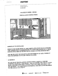
ALCOVE OR CLOSET INSTALLATION
An appliance installed in a closet shall have no other fuel-burning appliance installed in the
same closet. Each opening area in the door must have a minimum of 36 square inches.
These openings must not be obstructed. (Louvered door with equivalent air opening is
acceptable.)
36 sq.
Inches
-T
17"
inches
/e
3e sq.
0
0".
- 0"
//
/
FRONT
VIEW
Minimum installation clearances.
--I P2" SIDE VIEW
I
If possible, more clearance is recommended.
,"4A'_fAG
Admiral
7J
:n_jE_l-,_
"_lacji¢
C:_ef
240Edwards
Street,.SE
Cleveland,
Tennesse_
37311
7el:423-472-3333
Fax:423-478-67
_0
Gas dryers are equipped with a burner orifice for operation on NATURAL gas. If the dryer
is to be operated on LP (liquid propane) gas, it must be converted for safe and proper
performance and must be converted by a qualified service technician. Conversion kits
from NATURAL to LP, or LP to NATURAL are available through your local Maytag
dealer (see Accessories). If other conversions are required, check with the local gas utility
for specific information concerning conversion requirements.
a 1/2" gas supply line is recommended and must be reduced to connect to the 3/8" gas line
on the dryer.
Additionally, a 1/8" N.P,T. (National Pipe Thread) plugged tapping, accessible for test
gauge connection, must be installed immediately upstream of the gas supply connection to the
dryer.
HIGH PRESSURE TESTING
The dryer and its individual shutoff valve must be disconnected from the gas supply piping
system during any pressure testing of the system at test pressures in excess of i/2 psig
(3.45kPa).
LOW PRESSURE TESTING
The dryer must be isolated from the gas supply piping system by closing its individual
manual shutoff valve during any pressure testing of the gas supply piping system at test pressures equal to or less than 1/2 psig (3.45 kPa).
DO NOT re-use old flexible metal gas line. Flexible gas line must be design certified by
American Gas Association (CGA in Canada). NOTE: Any pipe joint compound used must
be resistant to the action of any liquified petroleum gas.
NOTE:
As a courtesy, most local gas utilities will inspect a gas appliance installation.
GAS IGNITION
This dryer uses an automatic ignition system to ignite the burner. There is no constant
burning pilot.
<;"Mla
"
240Edwards
Street,SE
Cleveland,
Tennessee
37311
Tel:423-4723323
_ax:a23-478-5770
ELECTRICAL
NOTE:
REQUIREMENTS
Wiring diagram
is located inside the control console.
WARNING - To
prevent unnecessary
risk of fire, electrical
shock or personal
injury, all wiring and
grounding must be
done in accordance with local
codes, or in the absence of local
codes, with the National Electrical
Code, ANSI/NFPA (for the United
States) or the Canadian Electrical
Code CSA C22.1 (for Canada).
GROUNDING
This dryer must be grounded.
In the event of malfunction or breakdown, the ground wilt
reduce the risk of electrical shock by providing a path of least resistance for electric current.
GAS MODELS
This appliance is equipped with a cord having an equipment-grounding
conductor and a
grounding plug. The plug must be plugged into an appropriate outlet that is properly
installed and grounded in accordance with all local codes and ordinances.
WARNING Improper connection
of the equipment
groundingconductor
can resultin a risk of
electric shock.
Check with a qualified electrician
or serviceman if you are {n doubt as
to whether the appliance is properly
grounded.
[]
MA'ffA(;
.,_dmlral71
===.J_._N-,_
"_}_ie
¢=,_ef
240 EdwardsStreet SE
Cleveland,Tennessee37311
Tel:423-472-3333
Fax:423-478-67;0
Do not modify the plug provided with the appliance - if it will not fit the outlet, have a
proper outlet installed by a qualified electrician.
l
An external ground wire, clamp and screws are provided for assistance in meeting local
codes. Where approved, it is recommended this additional ground be installed. A suitable
external ground connection MUST be determined prior to wire hookup.
NEVER CONNECT GROUND WIRE TO PLASTIC PLUMBING LINES, GAS LINES OR
HOT WATER PIPES.
ELECTRIC MODELS
U.S. MODELS ONLY
This electric dryer must be connected to a grounded metal, permanent wiring system; or an
equipment grounding conductor must be run with the circuit conductors and connected to the
equipment grounding terminal on the back panel.
Electric models are shipped with a ground strap connected from the neutral terminal block
post to the frame of the dryer. The use of this strap is permitted by the National Electrical
Code. If the local code prohibits the use of the ground strap, the dryer must be grounded in
accordance with local codes.
240 EdwardsStreet, SE
Cleveland,Tennessee37311
Tel:423-472-3333
Fax:423478-5710
ELECTRICAL
CONNECTIONS
BEFORE OPERATING
Section.
OR TESTING, follow all grounding instructions in Grounding
An individual branch (or separate) circuit serving only this appliance is recommended.
NOT USE AN EXTENSION CORD.
DO
GAS MODELS
A 120 volt, 60 HZ electrical supply, with a 15 ampere fuse or circuit breaker is required.
ELECTRIC MODELS
To avoid the possibility of electrical shock, the dryer must not be connected to a 120 volt
2-wire circuit.
The electrical supply circuit should be fused through a 30 ampere fuse or circuit breaker on
both sides of the line.
If a power cord is used, the cord should be plugged into a 30 ampere receptacle.
U.S. MODELS
Maytag electric dryers are manufactured to operate on 120/240 volt, 60 HZ AC approved
electrical service. Should the dryer be operated on a 120/208 volt electrical system, the dryer
must be converted. A heating element conversion kit is available (see Accessories).
The power cord is NOT provided with U.S. electric model dryers.
IMPORTANT:
When permitted by local codes, the dryer electrical supply may be connected by means of a new power supply cord kit, marked for sue with clothes dryer that is
U.L. listed, rated at 120/240 volts minimum, 30 amperes with three No. 10 copper wire
conductors terminated with closed loop terminals, open-end spade lugs with turned up ends or
with tinned leads.
Do not reuse a power supply cord from an old dryer.
The power cord or electric supply
C_s_om_r
_r,,i_
_r'l_l_
_
240EdwardsStreet.SE
C[evelan&Tennessee27311
TeJ:423-472-3333
Fax:423 478-67i0
wiring must be retained at the dryer cabinet with a suitable UL listed strain relief.
If the dryer is to be installed in a mobile home or an area where local does do not permit
grounding through neutral, only a 4 conductor power cord, rated and terminated as above,
may be used.
CANADIAN MODELS
All Canadian Models are shipped with the power cord attached.
NOTE:
It is not permissible to convert a dryer in Canada to 208 volts.
MA_ 1-AG
Admiral
_1
_,,.;'ENN-,,_
_'Magic
C_ef
k
CusTomer
Ser,'.ce
_,_1_;
240EdwarcsStreet,SE
C',eve!and,
Tennessee
37311
Tel:a23-4722333
Fax:423-478-6710
ADDITIONAL
INFORMATION
50 HERTZ OPERATION
This Maytag dryer is manufactured for operation on 60 HZ AC approved electrical service.
The dryer is not designed for use on 50 HZ AC electrical service and conversion of the
product from 60 to 50 HZ operation is not recommended. For additional information on 50
HZ products, write MAYTAG INTERNATIONAL, INC., 8700 BRYN MAWR AVE.
CHICAGO, ILLINOIS 6063 i. Phone 312-714-0100.
INSTALLATION
ACCESSORIES
- Vent hood - 4" (10.16 cm) opening.
- Aluminum pipe - 4" x 24" (10.16 cmx 60.96 cm).
- Aluminum elbow - 4" (10.16 cm).
- Aluminum window plate - 15" x 20" (38.10 cmx 50.80 cm) -4" (10.16 cm) hole.
- Exhaust deflector kit.
- Flexible aluminum vent duct -4" (10.16 cm) diame{er -38" (81.28 cm) length stretches to
8' (2.44 m).
- Clamp for flexible aluminum duct.
- Exhaust duct kit for base or left side exhausting.
- Dacron lint bag.
- Bracket for exhaust deflector.
- Rectangular vent kits.
- NAT to LP conversion kit.
- LP to NAT conversion kit.
- Anchor Bracket kit.
- Heating Element Conversion kit.
- Exhaust kit.
REPLACEMENT
PARTS AND ACCESSORIES.
If your dryer requires replacement parts or accessories, contact the dealer from whom you
purchased your dryer or Maytag Customer Assistance, 240 Edwards St. SE, Cleveland, TN
37311, phone 423-472-3333, for information on the nearest authorized Maytag Parts Distributor.
Dryer Door reversal instructions are in User Guide.
.MA_TAG
Adrn]r_al _J
]I_I_JJE N N ._IR
_gic
_,e(
240Edwar#s
SFeeT,
SE
C[evelandrTe£nessee
37311
Te1:423-472-3333
Fax:423-478-6710
TO INSTALL
1.
Move dryer to an appropriate location for installation. Consider installing the dryer
before the washer in side-by-side installations, to allow access to gas, electrical, and exhaust
connections.
Lay two of the carton corner posts on the floor. Tip the dryer forward on its front so it will
lay across both corner posts.
2.
Remove the crate wires holding the crate bast to the base frame. This can be done with
a screwdriver.
v-\
r"J
'oJ
L-
_YfAG
Admiral 7]
m_EN,"i-,-x_tq
"_Ma_i¢
¢_ef
Customer
Service
_/_
240Edwards
Street.SE
Cleveland.
Tennessee
373f
Tel:423472-3333
Fax:423-478-6710
3.
Loosen the leveling locking nuts and install the vinyl feet.
\
4.
,
Set the dryer back in an upright position.
5.
Review the exhaust section on the previous pages before installing the exhaust system.
Install the ductwork from the dryer to the exhaust hood. The crimped end of the duct sections must point away from the dryer. DO NOT use sheet metal screws when assembling
rigid ducting. These joints should be taped. Never use plastic flexible exhaust material.
C_0mer
S0_i_e
hl[AYT._G
2:0 Edwards
Street,SE
C;eveland,
Tennessee
37311
Tel:423-472-3333
_a×:423-478-6710
- Tip for tight installations, install section of exhaust system to the dryer before moving the
dryer in place. Use duct tape to secure this section to the dryer. Do not cover air louvers on
dryer cabinet.
INSTALLATION
Parts and literature are packaged inside the dryer drum.
6.
GAS DRYER SECTION
To Make The Gas Connection
Review the gas requirements on the previous pages of these instructions.
1.) Remove the pipe thread protective cap.
.',/,.bV'CI'A6
Admiral
7J
....... .;EN','U-,,_J_
"_'_lagic
Chef
:_s_omer
Se_vic_
,ti_4_
240Edwards Street,SE
Creveiand,Tennessee37311
TeJ:423-472 3333
Fax:423-478-87!0
2.) Apply pipe joint compound or about 1 1/2 wraps of Teflon tape over the threads.
NOTE: Pipe joint compound must be resistant to the action of any liquified petroleum gas.
3.) Connect the gas supply to the dryer.
Securely tighten the gas line fitting over threads.
4.) Turn on the gas supply. Check all gas connections for leaks using a soap solution. If
bubbles occur, tighten the connections and recheck. IN) NOT use an open flame to cheek
for gas leaks.
NPT
P_ug
5.) ADDITIONAL GROUNDING CONNECTIONS
Review the electrical requirements on the other pages of these instructions.
Connect the ground wire to the back of unit using the wire supplied (in accessory package).
Secure the other end of the ground wire with a clamp to a grounded COLD water (metal)
pipe.
240Edwards
Street,SE
Cleveiand,
Tennessee
,373;1
Tel:423-472-3333
Fax:423-478-6710
6,
ELECTRIC
DRYER SECTION
To Make The Electrical Connection
Review the electrical requirements on the other pages of these instructions.
IMPORTANT - The dryer frame is grounded to the neutral conductor at the terminal block.
If the codes do not permit grounding through the neutral, refer to 4 WIRE SYSTEM CONNECTIONS.
Remove the terminal block cover plate.
Insert the power cord with a U.L. listed strain relief through the hole provided in the cabinet
near the terminal block. Note, a strain relief must be used.
3-WIRE SYSTEM CONNECTIONS
The neutral (white or center wire on power cord) conductor must always be connected to the
center (silver colored) post of the terminal block.
Secure the power cord to the terminal block. Do not loosen the nuts already installed. Be
sure they are tight. Use a 3/8" deep well socket.
If the power cord has terminals, place the terminals over the existing nuts on the posts.
Secure in place using the nuts provided in the accessories package. If the power cord does
not have terminals, use the cupped washers ahead of the nuts.
Connect the other two wires of the power cord to the outer posts of the terminal block using
the nuts provided in the accessory package.
Be sure the terminal block nuts are tight. Secure the power cord in position. Tighten the
strain relief screw(s) in order to clamp the strain relief to the cord.
Replace the terminal block cover.
BEFORE OPERATING OR TESTING, follow the grounding instructions on the other
pages of these instructions.
_'_ MAYFAG
ldm|ra|
7J
_Im,JEN_I-_
"_Magic
Chef
-:
C_s_omer
S{r_ice
,A_I]_
240Edwards
Street,SE
Cleveland,
Tennessee
37311
TeL423-472-3333
Fax:423-478-671G
4-WIRE SYSTEM CONNECTIONS
Remove the ground strap screw from the terminal block support. Fold the ground strap over
so both ends of the ground strap are attached to the center terminal block post.
Connect the neutral white conductor of the cord to the center (silver) colored post of the
terminal block. Connect the grounding (green) wire of the cord to the terminal block support
using the ground strap screw.
Connect the red and black wires of the cord to the outer posts of the terminal block.
Be sure the terminal block nuts are tight. Secure the power cord in position.
strain relief screw(s) in order to clamp the strain relief to the cord.
Tighten the
Replace the terminal block cover.
WARNING: If converting from &wire electrical systems to 3-wire, the ground strap must
be reconnected to terminal block support to ground the dryer frame to the neutral insulator.
240EdwardsStreet, SE
CEeveJand,
Tennessee37311
Tel:423-472-3333
Fax:423-478-6710
©
C.
4 Wire
System
®
Neutral
f
Suppo_
_MA?
I-AG
Adm,
iz_i_J
_.;EN;_-,_P
_'_#
_qiC
Chef
240Edwards
Street.SE
Cleveland&
Tennessee
37311
Tel:423-472-3333
Fax:423-478-6710
- Improper connection of the equipment-grounding conductor can result in a risk of electrical
shock. Check with a qualified electrician or serviceman if you are in doubt as to whether the
appliance is properly grounded. Do not modify the plug provided with the appliance - if it
will not fit the outlet, have a proper outlet installed by a qualified electrician.
- To prevent unnecessary risk of fire, electrical shock or personal injury, all wiring and
grounding must be done in accordance with the National Electrical Code ANSI/NFPA,
No.70-Latest Revision (for U.S.) or the Canadian Electrical code CSA C22.1 - Latest Revision and local codes and ordinances. It is the personal responsibility and obligation of the
appliance owner to provide adequate electrical services for this appliance.
- All gas installations must be done in accordance with the National Fuel Gas Code
ANSI/Z223.1-Latest Revision (for the U.S.) or the CAN/CGA-B149 Installation CodesLatest Revision (for Canada) and local codes and ordinances.
[]
,MA'_L-_G
Admiral
7J
_",_ENN-_d;a
.:y _aeJi¢
O_ef
C_st0me_
S_,_
,tl_41Ayg__qlG
240 EdwarusStreet, SE
Cleveland Tennessee37311
Tei: 423--'72-3333
Fax:J-23-478-6710
7o With a level, check the dryer, and make necessary adjustments to the leveling legs.
Once level, tighten the leveling leg locking nuts with a wrench.
8.
To reverse dryer door direction, see User Guide for instructions.
9. At this time, make sure all gas, exhaust and electrical connections are complete.
dryer in, and check operation by using the check list below.
Plug
10.
(Gas models only) The burner may not ignite initially due to air in the gas line.
Allowing the dryer to operate on a heat setting will purge the line. If the gas does not ignite
within five minutes, turn the dryer off and wait 5 minutes. Be sure the gas supply to the
dryer has been turned on. In order to confirm gas ignition, an opening in the lower front
panel between the panel screws exists for viewing the flame. Replace the hole plug after
viewing.
[] MA'_r,,,C__.dmtra|_'l
_JEr_-,_t=
"ffl4acjic e.hef
Cu_t0mor
S_r*_o
,.,I]_dl]C'J_iG
240 EdwardsStreet, SE
Cleveland,Tennessee37,311
TeL423472 3333
Fax:423-478-6710
INSTALLATION
CHECK LIST
--Dryer is plugged in.
--Exhaust ductwork is hooked up and joints taped. DO NOT use plastic duct. Use only rigid
or stiff walled flexible metal vent material,
--Dryer is level and all legs firmly on the floor, with the lock nuts tightened.
--Gas modelsA) Gas turned on
B) No gas leaks
--Dryer operating properlyA) Dryer runs
B) Dryer heats
C) Dryer shuts off
--Demonstrate use to the consumer.