1
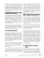
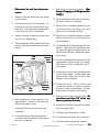
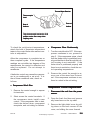
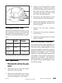
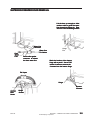
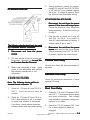
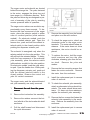
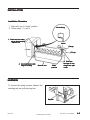
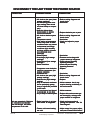
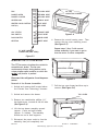
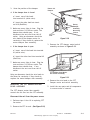
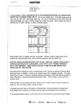
8. Release the three locking tabs fan shroud
by pushing back on the outer box
assembly and pulling foward on the fan
shroud. (See Figure 2-7)
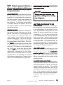
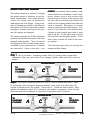
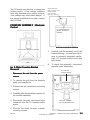
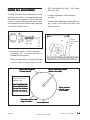
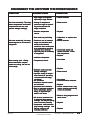
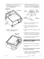
10. Disconnect the fan motor leads. The
wires are self-locking and it is important
to squeeze the clip before pulling the
leads off the terminals. (See Figure 2-9)
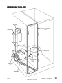
FAN SHROUD
LOCKING TABS
FAN SHROUD
REAR
MOTOR
BRACKET
FAN
MOTOR
MOUNTING
S C R E W S FAN BLADE
FAN
SCHROUD
Figure 2-9
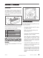
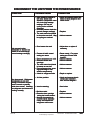
11. Remove the fan shroud assembly and
place it on a work surface.
OUTER
BOX
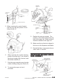
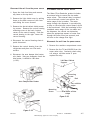
12. Remove the screws that secure the
motor bracket assembly to the fan
shroud.
Figure 2-7
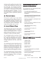
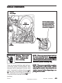
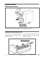
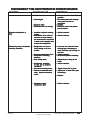
9. Carefully remove the fan shroud
assembly. (See Figure 2-8)
FAN SHROUD
ASSEMBLY
13. Remove the fan blade by pulling it off the
shaft.
14. Remove the screws that secure the rear
bracket to the front bracket. Remove the
motor from the rear mounting bracket.
15. Install the new part and all components
in reverse order of removal.
CHECKING THE CZT DAMPER
MOTOR/DOOR ASSEMBLY
Disconnect the unit from the power source.
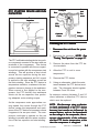
1. Perform steps 1 thru 8 in checking CZT
fan motor.
Figure 2-8
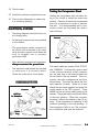
Note: The following test should be made by
a qualifed service Technician.
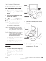
2. Using the test cord shown in Figure 2-1,
make the following connection to CZT PC
board wire harness connector.
16010154
SECTION 2. COMPONENTS
©2000 Maytag Appliances Sales Company
2-3