1
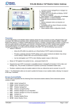
Model 8370
ACCUBALANCE®
Flow Measuring Hood
Operation and Service
Manual
September 1998
P/N 1980145 Rev B
Model 8370
ACCUBALANCE®
Flow Measuring Hood
Operation and Service
Manual
September 1998
P/N 1980145 Rev B
SHIP TO:
TSI Incorporated
500 Cardigan Road
Shoreview, MN 55126
U.S.
Sales &Customer Service:
(800)777-8356/(651)490-2711
Fax:
(651)490-2874
MAIL TO:
TSI Incorporated
P.O. Box 64394
St. Paul, MN 55164
INTERNATIONAL
Sales &Customer Service:
+1-651-490-2711
Fax:
+1-651-490-2874
©
Copyright
TSI Incorporated/Decmber 1996/All rights reserved.
Address
TSI Incorporated/500 Cardigan Road
P.O. Box 64394
St. Paul, MN 55164/USA
Fax No.
(651) 490-2874
Limitation of Warranty and Liability
Seller warrants that this product, under normal use and service as described in the operator's manual,
shall be free from defects in workmanship and material for a period of twenty-four (24) months, or
the length of time specified in operator's manual, from the date of shipment to the customer. This
limited warranty is subject to the following exclusions:
1. Batteries, hot wire or hot film sensors and certain other components when indicated in
specifications are warranted for a period of 90 days from the date of shipment to the customer.
2. With respect to any repair services rendered, seller warrants that the parts repaired or replaced
will be free from defects in workmanship and material, under normal use, for a period of 90 days
from the date of shipment to the customer.
3. Seller does not provide any warranty on finished goods manufactured by others. Only the
original manufacturer's warranty applies.
4. Unless specifically authorized in a separate writing by seller, seller makes no warranty with
respect to, and shall have no liability in connection with, any goods which are incorporated into
other products or equipment by the Buyer. All goods returned under warranty shall be at the
Buyer’s risk of loss, Seller’s factory prepaid, and will be returned at the Seller’s risk of loss,
Buyer’s factory prepaid.
THE FOREGOING IS IN LIEU OF ALL OTHER WARRANTIES AND IS SUBJECT TO THE
CONDITIONS AND LIMITATIONS STATED HEREIN. NO OTHER EXPRESS OR IMPLIED
WARRANTY OF FITNESS FOR PARTICULAR PURPOSE OR MERCHANTABILITY IS MADE.
THE EXCLUSIVE REMEDY OF THE USER OR PURCHASER, AND THE LIMIT OF THE LIABILITY
OF SELLER FOR ANY AND ALL LOSSES, INJURIES, OR DAMAGES IN CONNECTION WITH
THIS PRODUCT (INCLUDING CLAIMS BASED ON CONTRACT, NEGLIGENCE, STRICT
LIABILITY, OTHER TORT, OR OTHERWISE) SHALL BE THE RETURN OF THE PRODUCT TO
THE FACTORY OR DESIGNATED LOCATION AND THE REFUND OF THE PURCHASE PRICE,
OR, AT THE OPTION OF SELLER, THE REPAIR OR REPLACEMENT OF THE PRODUCT. IN NO
EVENT SHALL SELLER BE LIABLE FOR ANY SPECIAL INCIDENTAL OR CONSEQUENTIAL
DAMAGES. SELLER SHALL NOT BE RESPONSIBLE FOR INSTALLATION, DISMANTLING,
REASSEMBLY OR REINSTALLATION COSTS OR CHARGES. NO ACTION, REGARDLESS OF
FORM, MAY BE BROUGHT AGAINST THE SELLER MORE THAN ONE YEAR AFTER THE
CAUSE OF ACTION HAS ACCRUED.
The purchaser and all users are deemed to have accepted the terms of this LIMITATION OF
WARRANTY AND LIABILITY, which contains the complete and exclusive limited warranty of seller.
This LIMITATION OF WARRANTY AND LIABILITY may not be amended or modified nor may any
of its terms be waived except by a writing signed by an authorized representative of seller.
Service Policy
Knowing that inoperative or defective instruments are as detrimental to TSI as they are to our
customers, our service policy is designed to give prompt attention to any problems. If any
malfunction is discovered, please contact your nearest sales office or representative, or call TSI's
Customer Service department at (651) 490-2711 or (800) 777-8356.
Contents
About this manual
1
Introduction
3
Chapters
1
Setup
Unpacking
Parts Identification
Keypad
Display
Preparing the Instrument for Use
Display Units
Installing the Batteries
Start Up
Continuous Reading Mode
Averaging Mode
Selecting Flow Direction
Taking a Flow Measurement
Turning the ACCUBALANCE Off
Automatic Shut-off
5
5
7
9
10
11
14
14
15
15
15
16
16
17
17
2
Operations in More Detail
Changing Hoods
Switching On the Power
Selecting Flow Direction
Continuous Reading Mode
Averaging Mode
Selecting Flow Units
Selecting the Time Constant
Changing DIP Switch Settings
Low Battery Warning
Automatic Shut-off
Connecting the Optional Printer
19
19
26
26
27
27
28
28
29
32
32
33
i
RS-232 Serial Output
33
3
Maintenance
Fabric Hood
Meter
Manifold
Calibration
35
35
36
36
37
4
Troubleshooting
39
Appendices
A
B
C
D
E
Standard Flow vs. Actual Flow
Back Pressure
ACCUBALANCE Serial Interface Connections
Return Mode Low Flow Corrections
Specifications
41
43
45
47
49
Tables
1
1a
1b
2
3
4
5
List of Components
List of Components Model 8370-3
List of Components Model 8370-5
DIP Switch Settings
Printout Examples
Hood Fabric Part Numbers
Troubleshooting the ACCUBALANCE
5
6
6
32
33
35
39
Illustrations
1
2
3
4
5
6
7
ii
The ACCUBALANCE and Accessories
ACCUBALANCE Components
Electronic Meter Membrane Switch
Electronic Meter Display
An Easy Way to Begin Assembly
Installing a Support Pole
Assembled 2 ft x 4 ft Frame
7
8
9
10
12
13
20
8
9
10
11
12
13
14
15
16
17
18
Installing a Support Pole
Assembled 1 ft x 4 ft Frame
Assembled 1 ft x 5 ft Frame
Assembled 3 ft x 3 ft Frame
ACCUBALANCE Lying Face Down
Location of DIP Switches
Flow Sensing Tube Out of Place
Pressure Drop Through the ACCUBALANCE
9-Pin, RS-232 Serial Interface Connections
25-Pin, RS-232 Serial Interface Connections
25-Pin to 9-Pin, RS-232 Serial Interface Connections
22
23
24
25
30
31
37
44
45
46
46
iii
iv
About this manual
This manual explains how to set up, operate and maintain the Model
8370 ACCUBALANCE Flow Measuring Hood. Read it thoroughly before
using the instrument.
Formatting and Typography
Note that step-by-step instructions are numbered in boldface type: 1,
2, 3, etc., set flush-left against the margin.
References to the front panel keys on the ACCUBALANCE, along with
the instrument's displayed readout, are represented in this manual by
the typeface called Helvetica Narrow. In addition to the different typeface,
displayed messages appear in quotes.
When reference is made to other sections of the manual, the section
title is italicized.
Example: The "HOLD" message will appear along with a flow value
after you have activated the HOLD button (from Display in Chapter 1).
HELP!
If you need technical assistance with this instrument, have questions
about the manual, or your flow hood needs repair or recalibration
please call TSI's Insustrial Test Instruments Group at (651) 490-2711 or
✟
(800) 777-8356.
1
2
About this manual
Introduction
The TSI Model 8370 ACCUBALANCE is an instrument designed to
measure the air flow from diffusers and grilles or the air flow entering
exhaust outlets. The ACCUBALANCE is lightweight and easy to use.
The instrument can display the measured air flow in three different
units: standard cubic feet per minute (SCFM), standard liters per
second (Std l/s) and standard cubic meters per hour (Std m3/hr).
The ACCUBALANCE consists of a fabric hood, a molded plastic base
which contains an electronic meter, and a flow sensing manifold
located within the base. Air flowing through the hood is measured by
a hot-film sensor located in the central hub of the flow sensing
manifold. The twenty-four pairs of flow sensing ports in the manifold
are strategically located so that the ACCUBALANCE provides the highest
degree of measurement accuracy, even in non-uniform flow
conditions.
The ACCUBALANCE is temperature-compensated to display a standard
flow rate: SCFM, Std. l/s and Std. m3/hr. Standard flow rate is
defined as the volumetric flow rate at standard conditions of 70°F
(21.1°C) and 14.7 pounds per square inch (760 mmHg) barometric
pressure. Standard flow rate is the measurement used most often in
✟
ventilation applications.
3
4
Introduction
Chapter 1
Set Up
This chapter guides you through unpacking, setting up, and getting
started using your ACCUBALANCE. See Chapter 2 for a detailed
description of all operating features.
Unpacking
Carefully unpack the instrument and accessories from the carrying
case. Check the individual parts against the list of components in
Table 1. If any are missing or damaged, notify TSI immediately.
Table 1. List of components
Qty
Item
1
Model 8370 base
1
2 ft x 2 ft (610 mm x 610 mm) hood fabric
6
Frame support poles
4
2 ft (610 mm) frame tubing*
6
Right angle tubing connectors*
1
Battery holder
4
C-size batteries
1
Battery compartment cover
1
Carrying case
1
Operation and Service Manual
Part No.
1081388
1307060
1081390
1081262
1081584
1081279
1208018
1081458
1319067
1980145
*Four 2 ft frame tubings and four of the right angle connectors are
shipped assembled inside the top of the hood fabric.
5
Table 1a. List of components: Model 8370-3
Qty
Item
1
Model 8370 base
1
2 ft x 2 ft (610 mm x 610 mm) hood fabric
1
2 ft x 4 ft (610 mm x 1220 mm)hood fabric
1
1 ft x 4 ft (305 mm x 1220 mm)hood fabric
6
Frame support poles
6
2 ft (610 mm) frame tubing*
4
1 ft (305 mm) frame tubing
6
Right angle tubing connectors*
6
Straight tubing connectors
1
Battery holder
4
C-size batteries
1
Battery compartment cover
1
Carrying case
1
Operation and Service Manual
Part No.
1081388
1307060
1801065
1801066
1081390
1081262
1081260
1081584
1302833
1081279
1208018
1081458
1319067
1980145
Table 1b. List of components: Model 8370-5
Qty
Item
1
Model 8370 base
1
2 ft x 2 ft (610 mm x 610 mm) hood fabric
1
2 ft x 4 ft (610 mm x 1220 mm) hood fabric
1
1 ft x 4 ft (305 mm x 1220 mm) hood fabric
1
1 ft x 5 ft (305 mm x 1525 mm) hood fabric
1
3 ft x 3 ft (915 mm x 915 mm) hood fabric
6
Frame support poles
6
2 ft (610 mm) frame tubing*
4
1 ft (305 mm) frame tubing
6
Right angle tubing connectors*
6
Straight tubing connectors
1
Battery holder
2
1x tube connectors
4
C-size batteries
1
Battery compartment cover
1
Carrying case
1
Operation and Service Manual
Part No.
1081388
1307060
1801065
1801066
1801067
1801068
1081390
1081262
1081260
1081584
1302833
1081279
1081580
1208018
1081458
1319067
1980145
*Four of the 2 ft frame tubings and four of the right angle connectors
are shipped assembled inside the top of the hood fabric.
6
Chapter 1
Figure 1. The ACCUBALANCE and accessories
Included with every manual is a registration card. Look for yours at
the front of this manual. Please complete and mail it promptly; it
allows TSI to inform you of product updates.
Parts Identification
Before proceeding with assembly and use of the ACCUBALANCE, please
familiarize yourself with the various parts of the instrument. As you
read the next sections, refer to figures 2 - 4.
Set Up
7
Figure 2. ACCUBALANCE components
1. Hood fabric
2. Base
3. PRINT button in left handle
4. START/HOLD button in right handle
8
Chapter 1
Keypad
Figure 3. Electronic meter membrane switch
ON/OFF
Press to turn the ACCUBALANCE on and off.
PRINT
Press to transmit the displayed flow rate
measurement to the printer or other serial device.
Note that the button in the left handle performs the
same function.
DATA PORT
Printer (or other serial device) connection port.
(Remove Data Port Plug before connecting serial
device.)
Set Up
9
START/HOLD
In the Averaging Mode, press to start a new reading.
In the Continuous Reading Mode, press and release
to hold the value on display. Press again to resume
continuous readings. Note that the button in the
right handle performs the same function.
AVG/CONT
Press to switch between the Averaging and the
Continuous Reading Modes.
RETURN/SUPPLY
Press to switch between return air and supply air
measurements.
Display
Figure 4. Electronic meter display
Figure 4 shows the electronic meter display. All segments will be
shown momentarily each time you turn on the ACCUBALANCE.
10
Chapter 1
1.
Flow units: CFM (cubic feet per minute), l/s (liters per second),
and m3/hr (cubic meters per hour). The ACCUBALANCE indicates
flow already corrected to "standard" conditions (see Appendix A).
2.
Flow value: See specifications for range and resolution.
3.
Flow direction arrow: Indicates if supply or return air flow
calibration is being utilized by the ACCUBALANCE.
Notice: Be sure this arrow points in the direction of flow through the
ACCUBALANCE, otherwise the measurements made will be
inaccurate. To change the direction of the arrow, press the
RETURN/SUPPLY switch.
4.
Averaging mode: The "AVERAGE" message will appear on the
display when you have selected the three-second or six-second
averaging mode (See Averaging Mode section later in this chapter).
5.
Hold indicator. The "HOLD" message will appear along with a
flow value after you have activated the HOLD button.
6.
"LOW BATTERY". Displayed when batteries are getting near the
end of their useful life.
7.
"BATTERY" will appear along with a value on the display during
power-up to indicate the percent of battery life remaining.
Preparing the Instrument for Use
Hood Assembly
The ACCUBALANCE is shipped from the factory partially assembled
with the 2 ft x 2 ft nylon hood attached to the base. If you wish to use
another hood size, see Changing Hoods in Chapter 2.
Set Up
11
To complete the assembly of the 2 ft x 2 ft hood, follow these six steps:
1
Place the base of the ACCUBALANCE on the floor.
2
Lift the top of the fabric. Insert one end of a support pole into its
pole mount in the base of the ACCUBALANCE. There is a cup in
each corner of the frame to accept the other end of each support
pole. Helpful Hint: This step is made simpler by temporarily
resting the opposite corner of the fabric top on a table edge as
shown in Figure 5.
Figure 5. An easy way to begin assembly
12
Chapter 1
3
Grasp the support pole. Bend the pole slightly to insert the top
end of the pole into the support pole cup located in the corner of
the fabric frame as shown in Figure 6.
Figure 6. Installing a support pole
4
Insert the second support pole into the pole mount on the
opposite side of the ACCUBALANCE base.
5
Repeat step 3 for the second support pole.
6
Repeat steps 4 and 5 for the remaining two support poles.
Set Up
13
Display Units
The ACCUBALANCE is shipped with cubic feet per minute (CFM) as the
default flow unit (unless the metric version was ordered). If you wish
to change the units to l/s (liters per second) or m3/hr (cubic meters
per hour), see Changing Dip Switch Settings in Chapter 2
Installing the Batteries
The ACCUBALANCE requires four C-size batteries to operate. For your
convenience, four alkaline batteries are included with the
ACCUBALANCE.
To install the batteries, follow these three steps:
1
Remove the battery cover located behind the electronic meter on
the inner side of the ACCUBALANCE base. To remove the battery
cover, pull up on the latches located on the top and bottom of the
cover.
2
Place batteries in the battery holder located inside the battery
compartment. Follow the illustration on the battery holder for
correct battery orientation.
3
Replace the battery cover. Notice that the battery cover is
designed to fit only one way, with the tab pointing toward the
fabric. Engage the latches by pressing down on them.
WARNING:
Never leave batteries in the ACCUBALANCE for more
than two weeks. Leaking batteries can cause
electronic failure due to corrosion.
Notice: Remove batteries from the battery compartment during
shipping, travel and transport. Jostling may jar the batteries
loose and cause damage to the ACCUBALANCE .
14
Chapter 1
Start-Up
Press the ON/OFF button on the meter to turn on the power. The
display will initially indicate the percent of battery power remaining.
During start-up the ACCUBALANCE performs a self test of its electronic
functions. If an error is found, an error message will appear on the
display. Refer to Chapter 4, Troubleshooting, if an error message
appears. If no errors are found, the ACCUBALANCE will automatically
proceed to one of two measurement modes: continuous reading mode
or averaging mode.
Continuous Reading Mode
In the continuous reading mode, the measurement is updated on the
display every second. You can slow the update rate to once every two
seconds by changing the setting of DIP Switch 7. For more details, see
Changing DIP Switch Settings in Chapter 2.
The display continues to update until you press either the START/HOLD
switch on the keypad or the button on the right handle. The current
value will be held on the display along with the "HOLD" message. To
resume continuous readings, press one of the START/HOLD buttons
again. For more details about the continuous reading mode, see
Chapter 2.
Averaging Mode
In the averaging mode, a time-averaged reading is initiated each time
you press the START/HOLD switch on the keypad or the button on the
right handle. The time counts down from three seconds on the
display. After the countdown, the average flow appears and remains
on the display along with the "AVERAGE" message. To initiate a new
reading, press one of the START/HOLD buttons again. You can select an
Set Up
15
averaging time of six seconds by changing the setting of DIP Switch 6.
See Changing DIP Switch Settings in Chapter 2. For more details on the
averaging mode, see Chapter 2.
Selecting Flow Direction
Each ACCUBALANCE is calibrated for supply and return air separately
for increased accuracy. The ACCUBALANCE will assume that air is
flowing in the same direction as the arrow on the right-hand side of
the display. Be sure this arrow points in the direction of flow through
the ACCUBALANCE, otherwise measurements will be inaccurate. To
change the direction of the arrow, press the RETURN/SUPPLY switch.
Taking a Flow Measurement
You are now ready to start measuring flow rates. First, turn on the
ACCUBALANCE and select the appropriate flow direction. For
measuring supply air flow, the arrow must point down away from the
hood fabric; for return air flow measurements, the arrow must point
up toward the hood fabric.
Next, choose the Continuous Reading Mode and be sure that the
"HOLD" message is not on the display. If the "HOLD" message is on the
display, press either the START/HOLD switch on the keypad or the
button on the right handle to resume readings.
Finally, press the top of the ACCUBALANCE against the perimeter edge
of the diffuser or grille so as to form a seal. The electronic meter will
display standard flow readings.
If the readings are fluctuating, choose the averaging mode by pressing
the AVG/CONT switch on the keypad. In the Averaging Mode, it is
important to keep the ACCUBALANCE in place over the diffuser or grille
during the countdown and until the average reading appears on the
16
Chapter 1
display. A new average reading can be initiated by pressing the
START/HOLD switch or the button on the right handle.
When making a flow measurement, keep objects out of the flow path
at the base of the ACCUBALANCE (one foot clearance minimum).
However, it is acceptable to have a hand supporting the flow hood at
the bottom of the base.
Turning the ACCUBALANCE Off
To turn off the ACCUBALANCE, simply press the ON/OFF switch.
Automatic Shut-off
The ACCUBALANCE will automatically shut itself off if no switches or
buttons have been pressed for 15 minutes. This feature minimizes
accidental loss of battery power.
Set Up
✟
17
18
Chapter 1
Chapter 2
Operations in More Detail
This chapter explains how to change fabrics and assemble different
hood sizes and presents more detail on the various features of the
ACCUBALANCE.
Changing Hoods
The ACCUBALANCE is shipped with a 2 ft x 2 ft hood attached to the
base. Four other hood sizes are available from TSI and can be
purchased separately or as part of standard packages. Available hood
sizes are identified by the dimensions of the frame structure at the top
of the hood and include 2 ft x 4 ft, 1 ft x 4 ft, 1 ft x 5 ft and 3 ft x 3 ft .
To change hood sizes, first remove the hood currently attached to the
base. To remove the attached hood, first unlatch the cinch belt where
the fabric is attached to the base. Then remove the fabric from its
frame structure by peeling back the Velcro® from the aluminum frame
tubing. Notice that the fabric stretches around the outside, then up
and over the frame structure. The Velcro on the fabric reaches down
to mate with the Velcro on the frame structure. Notice also that all
Velcro surfaces on the frame tubing face inward. Finally, fold up the
fabric you just removed so that it can fit into one of the accessory
pockets inside the ACCUBALANCE carrying case. It is a good idea to
fold the fabric so that the tag identifying its size remains visible for
future reference.
19
2 ft x 4 ft Hood
To assemble and attach the 2 ft x 4 ft hood, carefully follow these 10
steps:
1
Build the 2 ft x 4 ft frame structure as shown in Figure 7 using six
2 ft aluminum frame tubing pieces, four right-angle tubing
connectors, and two straight tubing connectors. Remember to
construct the frame so that all Velcro surfaces face in (toward the
center of the structure).
Notice: Make sure that all support pole cups in the aluminum frame
tubing pieces are facing downward.
Figure 7. Assembled 2 ft x 4 ft frame
2
Unfold the 2 ft x 4 ft hood fabric.
3
Insert the frame into the fabric and fasten the fabric to the frame
using the Velcro surfaces. The fabric stretches around the
outside, then up and over the frame structure. The Velcro on the
fabric reaches down to mate with the Velcro on the inner surface
of the frame structure. When completed, the soft rubber gasket
material should lie in a straight line along the top surface of all
four sides of the frame.
20
Chapter 2
Notice: Be sure to press the Velcro surfaces firmly together. When
completed, the hood fabric will be stretched fairly taut and
will require good bonding of the fabric to the frame.
4
Stretch the cinch belt at the bottom of the fabric over the lip
around the top of the molded plastic base of the ACCUBALANCE.
Align the seams of the fabric panels with the pairs of screw heads
that hold the four pole mounts to the ACCUBALANCE base. Align
so that the cinch belt latch is on the side of the base opposite the
electronics meter.
5
Pull the strap at the latch very tight to attach the fabric to the
base. Make sure that the strap stays tucked under the protruding
lip all around the top of the base. Pay particular attention to
where the strap passes the handles.
6
Now it is time to install the support poles. You will find four
white marks on the inside top edge of the fabric. These marks
identify the location of cups on the underside of the frame tubing
that will accept the ends of the support poles.
At this time it is helpful to be near a table or some other thighhigh surface to help hold up the fabric while you install the first
support pole (refer to Figure 5 on page 12).
7
With the base of the ACCUBALANCE on the floor, lift the fabric
frame up so that a white mark is directly in front of you. Support
the opposite side of the frame structure on a nearby table or other
level surface as shown in Figure 5.
Take one support pole and insert one end into its pole mount in
the ACCUBALANCE base.
Bend the pole slightly to guide the other end into the
corresponding support pole cup located on the underside of the
frame near the white mark on the fabric.
Operations in More Detail
21
Figure 8. Installing a support pole
8
Repeat step 7 until all four support poles are installed.
9
Now that the hood is assembled and the fabric is stretched tight,
it is a good practice to check the rubber gasket around the top
edge of the ACCUBALANCE fabric. In order to achieve a good
straight alignment of the rubber gasket along the top of the frame
structure, you may need to peel back and re-attach small portions
of the Velcro surfaces.
10
Finally, at the corners, tuck the straight rubber gasket flaps under
the edges cut at an angle. This will create a virtually leak-free,
soft, pliant seal.
22
Chapter 2
1 ft x 4 ft Hood
To assemble and attach the 1 ft x 4 ft hood, carefully follow these 10
steps:
1
Build the 1 ft x 4 ft frame structure as shown in Figure 9 using
four 2 ft aluminum frame tubing pieces, two 1 ft aluminum frame
tubing pieces, four right-angle tubing connectors, and two
straight tubing connectors. Remember to construct the frame so
that all Velcro surfaces face in (toward the center of the structure).
Notice: Make sure that all support pole cups in the aluminum frame
tubing pieces are facing downward.
Figure 9. Assembled 1 ft x 4 ft frame
2
Unfold the 1 ft x 4 ft fabric hood.
Continue with steps 3 through 10, beginning on page 20.
1 ft x 5 ft Hood
To assemble and attach the 1 ft x 5 ft hood, carefully follow these 10
steps:
Operations in More Detail
23
1
Build the 1 ft x 5 ft frame structure as shown in Figure 10 using
four 2 ft aluminum frame tubing pieces, two 1x tube connectors,
two 1 ft aluminum frame tubing pieces, and four right-angle
tubing connectors. Remember to construct the frame so that all
Velcro surfaces face in (toward the center of the structure).
Notice: Make sure that all support pole cups in the aluminum frame
tubing pieces are facing downward.
Figure 10. Assembled 1 ft x 5 ft frame
2
Unfold the 1 ft x 5 ft fabric hood.
Continue with steps 3 through 10, beginning on page 20.
24
Chapter 2
3 ft x 3 ft Hood
To assemble and attach the 3 ft x 3 ft hood, carefully follow these 10
steps:
1
Build the 3 ft x 3 ft frame structure as shown in Figure 11 using
four 2 ft aluminum frame tubing pieces, four 1 ft aluminum frame
tubing pieces, four right-angle tubing connectors, and four
straight tubing connectors. Remember to construct the frame so
that all Velcro surfaces face in (toward the center of the structure).
Notice: Make sure that all support pole cups in the aluminum frame
tubing pieces are facing downward.
Figure 11. Assembled 3 ft x 3 ft frame
2
Unfold the 3 ft x 3 ft fabric hood.
Continue with steps 3 through 10, beginning on page 20.
Operations in More Detail
25
Switching On the Power
The power ON/OFF switch is located on the meter keypad of the
ACCUBALANCE. To turn the power on, momentarily press the ON/OFF
switch. The ACCUBALANCE will immediately light all display digits
and sound the buzzer. After a second, the approximate percent of
remaining battery life will be displayed. If fresh, new alkaline
batteries are used, the value will be near 100-percent. Other batteries,
such as NiCd batteries, may show a lower value even when they are
fully charged.
Notice: The percent power remaining will not be accurate for NiCd
batteries because they do not discharge linearly with power
use.
While the battery life is being displayed, the ACCUBALANCE will
automatically perform a series of self tests. If an error is detected, the
display will show an error number. Refer to Troubleshooting in Chapter
4 for interpretation of the error message.
If no errors are detected during start-up, the ACCUBALANCE will
proceed to one of its two operating modes: continuous reading mode
or averaging mode. As long as the batteries have not been removed or
the DIP switch settings have not been changed, the ACCUBALANCE will
return to the mode it was in when it was last used.
Selecting Flow Direction
The ACCUBALANCE is designed to accurately measure air flow in either
direction through the hood. For highest performance accuracy, every
ACCUBALANCE is calibrated with flow in each direction separately.
Therefore, it is very important that you select the flow direction using
the RETURN/SUPPLY switch on the keypad before you make a
measurement. The arrow in the upper right hand area of the display
will change direction each time you press the RETURN/SUPPLY switch
26
Chapter 2
on the keypad. Make sure the arrow is pointing in the direction of the
flow before you make a measurement.
Continuous Reading Mode
In this mode the display is continuously updated either once every
second or every other second. The ACCUBALANCE is shipped with a
one-second display update rate. The update rate can be changed to
once every two seconds by changing DIP switch 7 in the battery
compartment (see Changing DIP Switch Settings later in this chapter).
Changing the update rate to two seconds can help reduce fluctuations
in the readings (using the averaging mode will also help stabilize the
readings).
The flow rate can be held on the display by pressing the START/HOLD
switch on the keypad or the button in the right handle. This is a
valuable feature if you do not have the optional printer. The hold
function will allow you to set the instrument down to manually record
a measurement. Of course, the printer would make the job even easier.
With the printer, all you would have to do is press the PRINT button
instead of setting the instrument down and writing the value by hand.
To resume continuous readings when a value is being held on the
display, simply press the START/HOLD switch or the button in the right
handle.
Averaging Mode
This mode can be identified by the "AVERAGE" message appearing on
the display. You can toggle between continuous reading mode and
averaging mode by repeatedly pressing the AVG/CONT switch on the
keypad.
Operations in More Detail
27
In the averaging mode, the ACCUBALANCE takes flow measurements
for three or six seconds and then displays and holds the time-averaged
flow. The averaging time can be changed between three and six
seconds by changing DIP switch 6 inside the battery compartment (see
Changing DIP Switch Settings later in this chapter). The display will
count down while the ACCUBALANCE is taking flow measurements.
Notice:
You must keep the ACCUBALANCE in place during the
entire countdown and until the time-averaged
measurement appears on the display.
Selecting Flow Units
The ACCUBALANCE is capable of displaying measured flow rates in
three different measurement units: CFM (Cubic Feet per Minute), l/s
(Liters per Second), and m3/hr (Meters cubed per Hour). DIP
switches 3 and 4 control the display units. Refer to Changing DIP
Switch Settings later in this chapter to change the flow units.
Selecting the Time Constant
The ACCUBALANCE allows you to choose between two measurement
speeds in both the continuous reading mode and in the averaging
mode. In the continuous reading mode you may select either a onesecond or a two-second display update rate. The ACCUBALANCE is
shipped from the factory set up to operate at the one-second display
rate. You may change to a two-second display rate by adjusting
switch 7 under the battery cover (see Changing DIP Switch Settings).
The flow sensor in the ACCUBALANCE is extremely fast and actually
samples flow at a rate of 10 times per second. Thus, the values
displayed in the one-second mode represent an integration of 10
readings each. Likewise, the values displayed in the 2-second mode
represent an integration of 20 readings each. By selecting the slower
28
Chapter 2
(2-second) display rate, you will therefore see less variation in the
displayed values.
In the averaging mode, you may choose between a three-second and a
six-second averaging time period. The ACCUBALANCE is shipped set
up in the three-second averaging mode. You can change this by
changing the setting of switch 6 in the battery compartment (see
Changing DIP Switch Settings).
Changing DIP Switch Settings
You can change flow units and time constants by adjusting the settings
of the DIP switches located inside the battery compartment. To gain
access to the DIP switches, first turn off the ACCUBALANCE and lay
down the instrument with the electronic meter facing down as shown
in Figure 12.
Operations in More Detail
29
Figure 12. ACCUBALANCE lying face down
Remove the battery compartment cover by pulling up on the two
latches. You will see the switches numbered 1 through 8 in the corner
of the battery compartment. You may wish to remove or tilt up the
battery pack to allow easier access to the switches as shown in Figure
13.
30
Chapter 2
Figure 13. Location of DIP Switches
You may change the switch settings using the tip of a ball-point pen,
pencil, compass, small screwdriver, or other small, pointed object.
Refer to Table 2 for switch settings.
Operations in More Detail
31
Table 2. DIP Switch Settings
Switch Number Setting: Function
1
Leave in OFF position
2
Leave in OFF position
3,4
3 OFF, 4 OFF: Flow units = CFM
3 OFF, 4 ON: Flow units = l/s
3 ON, 4 ON: Flow units = m3/hr
5
Leave in OFF position for Rev A thru Rev M
Leave in ON position for Rev N and later
6
OFF: 3-second averaging in Averaging Mode
ON: 6-second averaging in Averaging Mode
7
OFF: 1-second display update rate in Continuous
Reading Mode
ON: 2-second display update rate in Continuous
Reading Mode
* See the serial number sticker on the unit to find the Rev level of
your ACCUBALANCE unit.
Low Battery Warning
When a battery power is running low, the message "LOW BATTERY" will
appear on the display. NOTE: The readings given by the ACCUBALANCE
when "LOW BATTERY" is displayed are still valid. Before the battery power
gets so low that valid flow measurements are not possible, the
ACCUBALANCE will shut itself off. When the "LOW BATTERY" message
appears, you usually have at least a half hour of running time before
the power gets so low that the ACCUBALANCE would automatically
turn itself off. If the optional printer is connected, the message "LOW
BATTERY" is printed just before the ACCUBALANCE turns itself off.
Automatic Shut-off
The ACCUBALANCE has an automatic shut-off feature to help save
battery life. If no switches or buttons are pushed for fifteen minutes,
the ACCUBALANCE will shut itself off.
32
Chapter 2
Connecting the Optional Printer
The ACCUBALANCE can be used with an optional portable printer. The
printer provides hard copy of selected flow rates and eliminates the
awkward task of manually recording flow rates while operating a flow
measuring hood. To connect a TSI Model 8925 Portable Printer to the
ACCUBALANCE, locate the interface cable that was shipped with the
printer. The cable has a modular RJ-45 (telephone type) connector on
one end and a 9-pin D-connector on the other end. Simply connect the
9-pin D-connector to the printer and the RJ-45 connector to the
ACCUBALANCE DATA PORT. If you find that the printer prints only
question marks "?", turn the printer off and then on again. For details
about how to operate the Model 8925 Portable Printer, refer to the
manual that was shipped with it.
RS-232 Serial Output
The DATA PORT on the ACCUBALANCE is used to interface to a printer,
digital data logger, or other serial device. The connector required for
the RS-232 port on the ACCUBALANCE is an eight-pin, modular RJ-45
type connector. For communications specifications and details about
the cable wiring configuration of the RS-232 port, refer to Appendix C,
ACCUBALANCE Serial Interface Connections.
The serial output from the ACCUBALANCE is transmitted in ASCII
format. Table 3 lists examples of the output from the ACCUBALANCE.
Table 3. Print-out Examples
Continuous Reading Mode
Flow = 435 CFM
Flow = 1580 m3/hr
Flow = 132 l/s
Operations in More Detail
33
Averaging Mode
3 sec Average = 435 CFM
3 sec Average = 1580 m3/hr
6 sec Average = 132 l/s
34
✟
Chapter 2
Chapter 3
Maintenance
The ACCUBALANCE is designed for long-term field use. If the
ACCUBALANCE is used with reasonable care, it should be able to make
precise measurements over a long time period. Some of the
components can be cleaned periodically. When cleaning the
components, please follow the instructions given below.
Fabric Hood
The hoods can be washed with mild detergent and cold water. When
washing the hood, keep the hood away from objects with sharp
corners or sharp edges. Careless cleaning may cause damage.
If the fabric gets ripped it should be replaced or repaired. Duct tape
can be placed over the rip on both sides of the fabric for temporary
repair.
To replace a damaged fabric or to order a different fabric size, contact
your local TSI distributor. To determine who your local TSI
distributor is, you may call TSI toll-free at 1-800-876-9874.
If you wish to order a new hood fabric, use the following part numbers
shown in Table 4.
Table 4. Hood Fabric Part Numbers
Fabric Hood Size
2 ft x 2 ft (610 mm x 610 mm)
2 ft x 4 ft (610 mm x 1220 mm)
1 ft x 4 ft (305 mm x 1220 mm)
3 ft x 3 ft (915 mm x 915 mm)
1 ft x 5 ft (305 mm x 1525 mm)
Part Number
800590
800591
800592
800593
800594
35
Frame Kit
1081263
It is recommended that you purchase a frame kit whenever you
purchase a hood other than the 2 ft x 2 ft size. The frame kit contains
all extra frame tubing and connectors required to build frames for the
various size hoods. The frame kit consists of the following parts:
4 pieces 1-foot frame tubing
2 pieces 2-foot frame tubing
6 pieces straight tubing connectors
Meter
The ACCUBALANCE has a built-in electronic flow meter. Do not try to
detach the meter from the base. The ACCUBALANCE should be used
and stored within the specified temperature range, 32 - 140º F (0-60º
C). The meter case, display screen and membrane switch can be
cleaned using a damp cloth with mild detergent solution. Do not
immerse the meter in water. Wipe the meter dry before use.
Manifold
If you notice that a tube in the flow sensing manifold has become
disengaged from its rubber holder as shown in Figure 14, work the
tube end back into the holder. The accuracy of the ACCUBALANCE is
not affected by having one or two tubes out of their holders; however,
it is a good practice to keep the tubes properly in place.
36
Chapter 3
Figure 14. Flow Sensing Tube Out of Place
If you observe the flow sensing taps of the manifold becoming clogged
with dust or other material, clean them with a damp cloth. The
manifold should be kept in place during cleaning. Do not apply
excessive forces on the grid tubes of the manifold. If any of the tubes
are bent or damaged, please contact TSI for repair information.
Calibration
TSI recommends an annual calibration for the ACCUBALANCE. For a
nominal fee, TSI will calibrate the unit and return it to you with a
certificate of calibration and NIST traceability. This 'annual checkup'
assures you of consistently accurate readings. To calibrate the
ACCUBALANCE, please ship TSI the complete package that includes the
meter, the base, the manifold and any fabrics used. Everything should
Maintenance
37
be packed carefully within the ACCUBALANCE carrying case and then
inside a proper shipping box, such as the original shipping box.
Ship directly to:
38
TSI, Inc.
ATTN: Customer Service
500 Cardigan Road
Shoreview, MN 55126-3996
✟
Chapter 3
Chapter 4
Troubleshooting
Table 5 lists the symptoms, possible causes, and recommended
solutions for common problems encountered with the ACCUBALANCE.
If your symptom is not listed, or if none of the solutions solves your
problem, please contact TSI.
Table 5. Troubleshooting the ACCUBALANCE
Symptom
No display
"LOW BATTERY"
on display
Flashing "0"
(Flow is under
range)
Possible Causes
Corrective Action
Unit not switched on
Press ON/OFF button.
Low or dead batteries
Replace the batteries.
Dirty battery contacts
Clean the battery
contacts.
Battery holder not
connected
Plug in battery
holder.
Low battery charge
Replace the batteries.
Dirty battery contacts
Clean the battery
contacts.
Trying to read too
low a flow
Flow may not be
measurable using the
ACCUBALANCE.
Object is blocking
flow through
ACCUBALANCE
Remove obstruction.
39
Table 5 (continued)
Symptom
Possible Causes
Corrective Action
Sensor grid tubes are
plugged
Clean the tubes.
ACCUBALANCE is not
sealing around
diffuser
Reposition the
ACCUBALANCE to
form a seal.
Flashing flow
value "> 0" (Flow
is over range)
Trying to read too
high a flow
Flow may not be
measurable using the
ACCUBALANCE.
Flow reading
fluctuates badly
The flow is
fluctuating
Use a longer time
constant.
"ERR2" appears
The flow sensor is
giving an erroneous
reading
Return to the factory
for service.
"ERR1" appears
Temperature
compensation sensor
is damaged
Return to the factory
for service.
Unit is or was
recently in ambient
temperature outside
of operating
temperature
Allow unit to
stabilize in the
operating
temperature range of
32 - 140ºF (0 - 60ºC).
The ACCUBALANCE
has detected a
calibration fault
Return to the factory
for service.
"ERR3" appears
✟
40
Chapter 4
Appendix A
Standard Flow vs. Actual Flow
Standard flow is defined as the volumetric flow rate of air at
"Standard" temperature and barometric pressure conditions of 70ºF
(21.1ºC) and 14.7 psia (760 mmHg). By contrast, actual flow is the
volumetric flow rate of air at local temperature and barometric
pressure conditions. It is common in ventilation test applications that
standard flow is the desired measurement parameter. The
ACCUBALANCE automatically indicates standard flow readings. There
is therefore no need to apply a correction factor; however, if you wish
to convert standard flow readings to actual flow readings, you must
apply an air-density correction factor:
⎡ 14.7 ⎤ ⎡ 460 + Tact ⎤
Actual Flow = (Standard Flow ) ⎢
⎣ Pact ⎥⎦ ⎢⎣ 530 ⎥⎦
where
Pact = Your local barom etric pressu re in psia .
Tact = Your air flow temperatu re in ° F.
Or
⎡ 760 ⎤ ⎡ 27315
. + Tact 1 ⎤
Actual Flow = (Standard Flow ) ⎢ 1 ⎥ ⎢
⎣ Pact ⎦ ⎣ 294.25 ⎥⎦
Pact 1 = Your local barometric p ressure in mm H g.
where
Tact 1 = Your air flow tem perature in ° C.
41
Example 1:
Suppose your air flow temperature is 55ºF and you local barometric
pressure is 13.5 psia, and the standard flow indicated on the
ACCUBALANCE is 200 (standard) CFM.
⎡ 14.7 ⎤ 460 + 55
Actual Flow = 200 ⎢
= 212 A ctual CFM
⎣ 13.5 ⎥⎦ 530
Example 2:
Suppose your air flow temperature is 25ºC, and your local barometric
pressure is 730 mmHg, and the standard flow indicated on the
ACCUBALANCE is 100 (standard) l/s.
Actual Flow = 100
42
760 ⎡ 273.15 + 25 ⎤
= 105 A ctual l s
730 ⎢⎣ 294.25 ⎥⎦
Appendix A
✟
Appendix B
Back Pressure
It is commonly known that a flow measuring hood may induce a back
pressure. In general, back pressures are caused by restrictions in the
flow path as well as frictional pressure losses. In order to improve
accuracy and sensitivity, all flow measuring hoods incorporate a
contracted flow section. The contracted section restricts the flow
through the hood which induces a back pressure. A hood having a
more abrupt contraction than the ACCUBALANCE may induce greater
back pressure due to the turbulence caused by the abrupt contraction.
In addition any apparatus within the hood, such as supporting poles
and the flow manifold, also induces some frictional pressure drop.
Back pressure may cause slight errors in the flow measurements.
Figure 15 shows the pressure drop through the ACCUBALANCE over its
entire flow range. As shown in the figure, the back pressure is only
0.05 in. H2O at a flow rate as high as 1000 CFM.
43
Figure 15. Pressure Drop through the ACCUBALANCE
If you wish to make back pressure corrections, you must first
determine the back pressure correction factor, Cb. The back pressure
correction factor, Cb, can be determined as follows:
Vo
Cb = ---V
(8-1)
where V and Vo are the average air velocities in the duct ahead of the
diffuser with and without the capture hood in place, respectively. With
the known correction factor, the back-pressure corrected flow can be
determined using Equation (8-2):
Back-pressure corrected flow = Displayed flow x Cb
44
(8-2)
✟
Appendix B
Appendix C
ACCUBALANCE Serial Interface Connections
A 9-pin cable (Model 8926) is available for use with the ACCUBALANCE
and the TSI Model 8925 Portable Printer. This cable allows a direct
connection between the ACCUBALANCE and the printer. Its connections
are as follows:
ACCUBALANCE
pin 1
pin 2
pin 3
tied together
pin 4
transmit data
pin 5
pin 6
signal ground
pin 7
tied together
pin 8
no connection
Signal Name
tied together
tied together
Printer
pin 1
pin 7
pin 2
pin 6
pin 3
pin 9
pin 5
pin 8
pin 4
Signal Name
receive data
signal ground
busy
Figure 16. 9-pin, RS-232 serial interface connections for Model 8925
Printer
All lines shown are connected, but only the data line going to the
printer and the ground are actually used in this configuration. The
pins labeled "tied together" are connected together inside the
ACCUBALANCE.
A 25-pin cable (Model 8927) is available for connecting the
ACCUBALANCE to a personal computer. This cable allows a direct
connection between the ACCUBALANCE and the computer. Its
connections are as follows:
45
Signal Name
tied together
tied together
tied together
transmit data
ground
tied together
ACCUBALANCE
pin 1
pin 2
pin 3
pin 4
pin 5
pin 6
pin 7
pin 8
Computer
pin 8
pin 5
pin 2
pin 6
pin 3
pin 22
pin 7
pin 20
Signal Name
carrier detect
clear to send
transmit data
data set ready
receive data
ring indicator
ground
data term ready
Figure 17. 25-pin, RS-232 serial interface connections for personal
computer
The pins labeled "tied together" are connected together inside the
ACCUBALANCE. This puts the "data set ready" and "clear to send" lines
at the proper logic level for your computer to receive data.
If you wish to connect the ACCUBALANCE to a computer which uses a
9-pin connector for serial communications, an adapter may be used.
This is a standard 25-pin to 9-pin adapter with male pins on the 25-pin
side and female pins on the 9-pin side. Such an adapter is supplied
with the Model 8927 Computer Interface Cable or is available from a
number of computer supply houses. Its connections are as follows:
9-Pin Female Side
pin 1
pin 2
pin 3
pin 4
pin 5
pin 6
pin 7
pin 8
pin 9
25-Pin Male Side
pin 8
pin 3
pin 2
pin 20
pin 7
pin 6
pin 4
pin 5
pin 22
Signal Name
carrier detect
receive data
transmit data
data term ready
ground
data set ready
request to send
clear to send
ring indicator
Figure 18. 25-pin to 9-pin, RS-232 serial interface connections
46
✟
Appendix C
Appendix D
Return Mode Low Flow Corrections
The ACCUBALANCE is calibrated in a vertical position. Thus, in the
Return Mode, air is flowing up through the ACCUBALANCE base and
then through the fabric hood.
When using the ACCUBALANCE in a horizontal orientation at flows
below 100 CFM (50 l/s), such as at a side wall return vent, the
ACCUBALANCE will read slightly lower than the true flow. At 80 CFM
(40 l/s), for example, the ACCUBALANCE will read low by 2 CFM (1
l/s). Therefore, you may wish to add 2 CFM (1 l/s) when the
indicated flow is 80 CFM (40 l/s); 3 CFM (1.5 l/s) at 50 CFM (25 l/s);
and 4.5 CFM (2 l/s) at 30 CFM (15 l/s) to obtain a more accurate
reading. No correction is required at flows greater than 100 CFM (50 l/s).
Notice:
This correction factor is necessary only in the Return
Mode. The Supply Mode does not require a correction.
47
48
Appendix D
Appendix E
Specifications
Flow Range
30-2,000 CFM (15-1,000 l/s,
50-3,500 m3/hr)
Accuracy
±5% rdg, ±5 CFM (±2.4 l/s, 8.5 m3/hr)
Operating Temperature Range
32-140°F (0-60°C)
Weight (using 24 in × 24 in Hood)
7 lb 6 oz (3.4 kg)
Hood Sizes Available
24 in × 24 in; (610 mm × 610 mm)
24 in × 48 in; (610 mm × 1220 mm)
12 in × 48 in; (305 mm × 1220 mm)
12 in × 60 in; (305 mm × 1525 mm)
36 in × 36 in; (915 mm × 915 mm)
Power
4 C-size batteries (4 alkaline batteries
provided)
Battery Life
At least 40 hours of continuous use
Carrying Case
26 in × 26 in × 7 in (660 mm × 660 mm
× 180 mm)
RS-232C Output
ASCII Character codes
1200 Baud
No parity
8 data bits
1 stop bit
No handshaking
These specifications are subject to change without notice.
✟
49
50
Appendix E