1
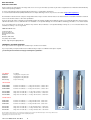
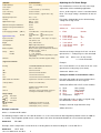
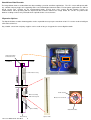
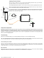
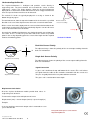
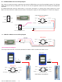
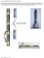
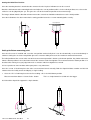
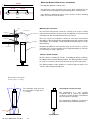
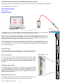
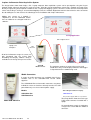
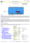
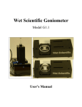
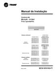
Geotechnical Instrumentation
In-Place-Inclinometer User Manual
SDI-12/RS485 Digital Network Device
Advantages
The In-place Inclinometer (IPI) is ideally suited for near real-time
measurement of lateral displacement of rock, soil and man made
structures.
Sensor strings can give a complete profile of vertical
or horizontal displacements.
Available in Uni-Axial and Bi-Axial sensor versions.
Low Power SDI-12 or RS-485 digital communications. IP68 rated in-line
network connection for fast installation & maintenance. Ideal for multiple
sensor applications with limited tube space.
Programmable averaging period for signal enhancement and noise
reduction
Digital data communication to remove noise
and simplify installation.
Ideal for monitoring the stability of natural and cut slopes, tunnels,
embankments and structural foundations for large structures.
Immersion Proof to 80 m
In-Place-Inclinometer
In-Place Inclinometers are typically used for monitoring subsurface deformations around excavations when rapid monitoring is
required or when instrumented locations are difficult to access for continued manual readings.
The sensors are computer driven, gravity-sensing transducers joined in a string by articulated rods, or mounted and they can be
installed equidistantly in the casing or concentrated in zones of expected movement.
With the in-place instrument, as many as 36 sensors are mounted in the casing and left semi-permanently in place. The sensors
are easy to install and maintain using the in-line digital network for all measurement operations. A single 3 core cable is all that is
required to communicate to the sensor chain.
Compared with conventional instruments, the in-place inclinometer hardware is in-expensive and simple to use. A complete
sensor chain cab be removed and deployed into a new location in most cases with little or no experience.
Signals from the different In-Place inclinometers can be stored into a data logger and access remotely via the Internet, or in real
time directly to a PC for local observation by construction/maintenance staff.
This product is integrated into the Q-LOG free data acquisition and display software package.
Last updated 21/11/2012
I-P-I User Mnaual V4 Jan 2013
1
Purpose of Monitoring
If the different parts of a structure should move uniformly by even large amounts, considerable damage could occur.
Structures affected by construction, or ground effected by a shift in water flow react by exhibiting movement. This movement is the
principal cause of construction related damages because the affected structure may be subjected to forces it was not designed for.
A building, for example, whose footings are settling on one side while the other side settles less or not at all will suffer tilting of some
walls structures. The change in the water table may cause movement of an embankment leading to a slip. The Keynes Controls
In-place-inclinometers have been designed to measure and report this type of structural movement.
Q-LOG Application Software
Download free at:
http://www.aquabat.net/downloads/QlogSetupv1207.zip
Features
Quick User Guide
Advanced rugged sensor technology utilising power management.
Lightning Protects as standard
In-line coupling for signal cable installation. Simplifies installation and
maintenance.
Calibrated range ±15 ±10 ±5 Deg
Programmable Sample Period :- removes unwanted vibration
Waterproof to 200 m.
Sensor strings can provide a complete profile of vertical and horizontal
displacements.
Digital data communications to minimise noise
The Keynes Controls range of inclinometers are intelligent devices and
transmit data directly across the RS-485 or SDI-12 digital network. The guide
is not meant as a teaching aid and some prior knowledge of using these two
networks is expected.
SDI-12 Sensor
Unless specified at the time of order a single sensor is set to use ID=0. If the
sensors are supplied as part of a kit then they will be pre-set to unique network
ID numbers.
Connect the sensor to any suitable data logger or PC supporting the SDI-12
network and issue the following commands.
Command: 0An! sets the sensor ID from 0 to ID = n 0A3! new ID=3
0M! start measurement 0D0! Get Data
Data will be returned. If using a Keynes Controls media converter then the
status LED’s will illuminate.
Calibration
RS-485 Sensor
Simple Command Structure
Unless specified at the time of order a single sensor is set to use ID=0. If the
sensors are supplied as part of a kit then they will be pre-set to unique network
ID numbers. This version of the sensor requires a break character to be sent
with the instruction. The break character is identified in the manual as the %
symbol.
All of the I-P-I models use the same command structure.
Connect the sensor to any suitable data logger or PC supporting the RS-485
network and issue the following commands.
aM! – starts a measurement
aC! – starts a concurrent measurement
aD0! – gets data from the sensor
Command: %0An! sets the sensor ID from 0 to ID = n 0A3! new ID=3
%0M! start measurement 0D0! Get Data
All sensors are calibrated at the Keynes Controls facility in the
UK. External calibration can be undertaken upon request.
Data will be returned. If using a Keynes Controls media converter then the
status LED’s will illuminate.
where a = Instrument ID Number
The Q-LOG software automatically inserts the correct break character when
identifying the network being used for communications.
I-P-I User Mnaual V4 Jan 2013
2
Guide Wheel
Mounting Bracket
Sensor Components - Vertical I-P-I Digital Sensors
In-place-inclinometers can be installed as a single sensor or as a chain of sensors making up a string of a set length.
An individual instrument typically consists of a body, wheel assembly and gauge tube.
Sensor Bodies - The I-P-I contains either single axis or bi-axis sensors but physically look identical.
Gauge-tubes -
The gauge tubes are available in various dimensions and when fitted to the sensor bodies make inclinometers
from 1 through to 3 metres in length.
Default Output Values - The Keynes Controls in-place-inclinometers default data type output is in mm/m.
Sensor Wheels -
Are used to link the different sensors together. The sensor wheel attaches to the bottom of the sensor body
and uses this wheel as a guide in the casing.
Warranty Information
The information in this document is subject to change without notice. Keynes Controls Ltd . has made a reasonable effort to be sure that the
information contained herein is current and accurate as of the date of publication.
Keynes Controls Ltd. makes no warranty of any kind with regard to this material, including, but not limited to, its fitness for a particular application.
Keynes Controls Ltd will not be liable for errors contained herein or for incidental or consequential damages in connection with the furnishing,
performance, or use of this material.
In no event shall Keynes Controls Ltd . be liable for any claim for direct, incidental, or consequential damages arising out of, or in connection with,
the sale, manufacture, delivery, or use of any product.
I-P-I User Mnaual V4 Jan 2013
3
WHAT WE PROVIDE
WARRANTY PROVISIONS
Keynes Controls Ltd . warrants the I-P-I range of tilt sensors for one year from date of purchase by the end user against defects in materials and workmanship
under normal operating conditions.
To exercise this warranty contact Technical Support at the phone or e-mail address listed below
for a return material authorization (RMA) and instructions. Complete warranty provisions are posted on our website at http://www.aquabat.net
The information in this document is subject to change without notice. Keynes Controls Ltd. has made a reasonable effort to be sure that the information contained
herein is current and accurate as of the date of publication.
Keynes Controls Ltd. makes no warranty of any kind with regard to this material, including, but not limited to, its fitness for a particular application. Keynes Controls
Ltd will not be liable for errors contained herein or for incidental or consequential damages in connection with the furnishing, performance, or use of this material.
In no event shall Keynes Controls Ltd . be liable for any claim for direct, incidental, or consequential damages arising out of, or in connection with, the sale,
manufacture, delivery, or use of any product.
HOW TO CONTACT US
Technical Support
Keynes Controls Ltd
Riseley Business Park
Riseley
Berkshire, RG7 1NW
Tel: (0044) 118 327 6067
E-mail: [email protected]
FIRMWARE & SOFTWARE UPGRADES
The In-place-inclinometer is upgrade able. Contact Keynes Controls Ltd. for details.
If you suspect that your In-place-inclinometer is malfunctioning or requires re-calibration and repair is required,
you can help assure efficient servicing by following these guidelines:
Part Number
Description
IPI-bar-1m
1m gauge bar for any IPI sensor
IPI-bar-1m
2m gauge bar for any IPI model
IPI-bar-1m
3m gauge bar for any IPI model
IPI-case-cap
Cap for I-P-I housing
SDI-12 network
IPI-D-15-SDI12
Dual Axis I-P-I Solid state - +/- 15 deg - SDI-12 Comms - sealed to 100 m
IPI-D-75-SDI12
Dual Axis I-P-I Solid state - +/- 7.5 deg - SDI-12 Comms - sealed to 100 m
IPI-D-25-SDI12
Dual Axis I-P-I Solid state - +/- 2.5 deg - SDI-12 Comms - sealed to 100 m
IPI-S-15-SDI12
Single Axis I-P-I Solid state - +/- 15 deg - SDI-12 Comms - sealed 100 m
IPI-S-75-SDI12
Single Axis I-P-I Solid state - +/- 7.5 deg - SDI-12 Comms - sealed 100 m
IPI-S-25-SDI12
Single Axis I-P-I Solid state - +/- 2.5 deg - SDI-12 Comms - sealed 100 m
RS-485 network
IPI-D-15-485
Dual Axis I-P-I Solid state - +/- 15 deg - RS-485 Comms - sealed 100 m
IPI-D-75-485
Dual Axis I-P-I Solid state - +/- 7.5 deg - RS-485 Comms - sealed 100 m
IPI-D-25-485
Dual Axis I-P-I Solid state - +/- 2.5 deg - RS-485 Comms - sealed 100 m
IPI-S-15-485
Single Axis I-P-I Solid state - +/- 15 deg - RS-485 Comms - sealed 100 m
IPI-S-75-485
Single Axis I-P-I Solid state - +/- 7.5 deg - RS-485 Comms - sealed 100 m
IPI-S-25-485
Single Axis I-P-I Solid state - +/- 2.5 deg - RS-485 Comms - sealed 100 m
The information in this document is correct at the time of printing. Keynes Controls Ltd withhold the right to make changes without notice.
Please contact Keynes Controls Ltd for the latest details regarding this product
Copyright Keynes Controls Ltd © 2011 - 2013
I-P-I User Mnaual V4 Jan 2013
4
SENSORS
SPECIFICATIONS
Calibrated Range
± 15 , ± 7, ± 2.5 Deg
Sensor Input
32 bit
Resolution
+/- 2 arc Seconds (+/- 0.01 mm/m)
Sensor Accuracy
±0.05% Full Scale
Repeatability
±0.01% Full Scale (Typical values only)
Operating Temperature
-20 to + 75 °C
Linearity
0.2% Full Scale
Digital Network Type
SDI-12 - 3 wire
RS-485 - 4 wire
Minimum Casing Internal Diameter
56 mm
Maximum Casing Internal Diameter
72 mm
Length
230 mm
Power Supply @ 12V DC
(SDI-12)
Typical values only
Ingress Protection
12 mA Dual Axis - measurement period
0.3 mA
Idle
16 mA Dual Axis - measurement period
2 mA
Idle
IP68 - rated 100 m - other ranges on request
Housing Material
316 stainless steel
Weight
560 g without cable
Signal Output
Digital engineering values Raw data using configuration commands
All I-P-I models support standard and enhanced
ID address modes. 0..9 A..Z
0 .. 100 m standard
0 .. 1 km standard
Increased can be achieved depending on signal
cable quality.
This product has a firmware upgrade facility
RS-485
Addressing Mode:
Range:
SDI-12
RS-485
Firmware
Supported Commands
Adjusting the Full Scale Range
The inclinometer can have the full scale range
adjusted to suit the monitoring application.
Over a small range the sensor is considered to be
linear. The range setting is undertaken in units of
mm/m
The factors shown below are the default factory
settings for 15 deg sensor.
Use command
aXCAn,val
Sets cal n to val
n
Field
Default
0
1
2
X-axis Offset
X-axis Range mm/m
X-axis Scale
0
250
1
3
4
5
Y-axis Offset
Y-axis Range mm/m
Y-axis Scale
0
250
1
therefore to change change the X-axis sensor to
operate over +/- 10 deg range use the command
aXCA1 175!
where 175 is in units mm/m
a = sensor ID number
Example
ID string
a13KEYNESCOINPINC001H001F004
aM!
aMC!
where a = ID number
start measurement
start measurement with CRC
aC!
concurrent measurement
aCC!
concurrent measurement with CRC
aD0! variable list A B C D E
5 parameters returned for each measurement
?! Query address
Find the sensor ID number
for a sensor with ID = 8 is to have the X-axis set to
operate over 10 deg range (175 mm/m).
Command: 8XCA1 175!
Setting the number of returned data values
The order and number of measured data values
from the inclinometer can be assigned:
Command: aXRA=”A B C D E” results variables
aXI n!
Integration Period milli-Seconds
where n is in ms
temperature offset in hundredths of degrees
n is integer in hundredths of a degree
aXCT n!
Range Settings
15 Deg
250 mm/m
Deg
175 mm/m
Deg
87 mm/m
Tilt-X
Tilt Y
Tilt-X
Tilt Y
Temperature
Units (mm/m)
Units (mm/m)
(Calibrated)
(Calibrated)
Deg C
The calibrated results are those assigned using
the command in ‘aXCAn’ above.
24 AWG Polyeurethene Covered
2 twisted pair (4 core) + foil shield
3 twisted pair (6 core) + foil seal
Electrical Cable
SDI-12
RS-485
A
B
C
D
E
Example, return tilt angle data items only:
3XRA=”A B C D”!
Example commands
where a = instrument ID number
The following example shows an I-P-I with ID number = 3 set to a measurement with integration period for all axis to 1000 ms
(1 second). Any integration period can be used to reduce the effect of unwanted vibration on a measurement operation.
Command:
3XI 1000!
Example, Set the temperature sensor offset to + 0.25 deg above the normal reading for a sensor with ID = 7
Command:
7XCT 250!
I-P-I User Mnaual V4 Jan 2013
5
Stand-Alone Data Recorder
The image below shows a standard low cost data recording system for stand-lone applications. The I-P-I sensors will operate with
any suitable 3rd party logger unit supporting SDI-12 or RS-485 digital communications. For low power applications the SDI-12
based sensors and recorder are the recommended option, and for large scale systems RS-485 network sensors are
recommended. When operating with the AquaLOG data recorder shown in the image below, the sensors are powered off
between readings and are only activated when required to take a measurement..
Expansion Options
The AquaLOG data recorder shown opposite can be expanded to accept up to a maximum of 36 I-P-I sensors or other intelligent
SDI-12 based devices.
Any suitable sensor from 3rd party suppliers can be used so long as it supports the correct digital network.
.
Support Assembly
& Protective Cap
SENSOR 1
X AXIS 1.086 MM/M
Y AXIS 2.456 MM/M
Inclinometer Casing
Guide Casing
Wheel assembly
with universal joint
Direction of movement
Spacer Tubing
Guide Wheel Slot
Bottom Cap
I-P-I User Mnaual V4 Jan 2013
Spacer Tube
6
Lightning Protection Scheme
All of the Keynes Controls tilt sensors contain integral lightning protection using a gas discharge
protection making them safe from anything but a direct strike.
For the lightning protection to work the sensor earth has to be connected to a good ground connection.
All the instrumentation inside the junction box should be connected to the main chassis earth. The main
chassis earth connects all the sensor cable sheaths to earth.
Wall
If a metal instrument box is used then a good quality, thick single core cable should connect the ground
spike to the box. Only a single earth point should be inserted into the ground to ensure no ground
potentials cause errors to the input signals.
Earth
1
5
2
4
3
Instrument Box
Tilt Sensor
Main Chassis
Earth tab
Instrument cable
Ground
Spike
Temperature Compensation
Although the temperature effects on the tilt sensor is tiny, and the results are automatically compensated for in the measurement
operation. When there is considerable temperature changes on the sensor then the effect can be seen in results and the effect
can be miss-interpreted as a physical movement. In this case recording the temperature values as part of the tilt measurement
operation is essential in order to detect this possible source of error. It is good practice to record the sensor temperature data
values as part of the logging program.
Troubleshooting
Maintenance and troubleshooting is reserved to periodically checking the sensor and cabling for damage.
For sensors deployed outside for long term deployments then the cable entry ports should be examined for corrosion that may
cause the signal cable to fail. The sensors are fully sealed units with no User serviceable parts.
Sensor Readings are unstable:
If there is a source of electrical noise nearby the sensor then the reading may be unstable. The source of noise can be motors,
generators or antennas. To minimise the noise effects ensure that the earth cable is attached to the sensor and terminated to a
suitable ground point. The earth cable is attached to pin-6 of the cable port.
Noise Reduction
All of the I-P-I ranges of sensors have a User programmable recording period in steps of 1 ms. This has the effect of removing
background vibration and enhancing the correct tilt value. The unwanted noise is averaged out
I-P-I User Mnaual V4 Jan 2013
7
L sin
The In-place-inclinometer is intelligent and provides results directly in
engineering units. The most common unit used with this sensor is mm/m
(milli-meters / metre). The image opposite shows the in-place-inclinometer
deployed on a vertical chain and the movement has been exaggerated to make
clear the expected movement that can be detected.
L sin
th
ng
Le
Understanding the Results
L
The total movement, from the top to the bottom of the chain and in a specified
direction is the sum of the displacements from each sensor in that direction.
=
The vertical I-P-I chain are typically deployed in a casing as shown in the
bottom image on page 6.
True
Vertical
Distance between
successive readings
All the sensors have to be deployed in the same mechanical orientation for the
results to be meaning full. Failure to mechanically align the sensors will cause
errors in the total movement calculation.
In practice the individual inclinometers are deployed equally spaced along the
I-P-I chain. There is a choice of spacer bars that fix the sensors to specified
points in the casing depending upon the sensor chain length and the required
number of monitoring points.
Tilt Angle
Vertical I-P-I Chain
Dual Axis Sensor Polarity
-Y
-Y
+X AXIS
-X
+X
-X
The adjacent Image shows the polarity of the sensor output readings from the
dual axis Inclinometer.
+Y
+Y
Single Axis Sensor Polarity
Dual-Axis Sensor Polarity
The adjacent image shows the polarity of the sensor output readings from the
dual axis Inclinometer.
+X AXIS
-X
Signal Connection
A glass seal is built into the top and bottom of the sensors This seal isolates
the signals from the cables to the electronics mounted inside the sensor case.
The pins are gold plated and so are protected from corrosion.
Single-Axis Sensor Polarity
The glass seal is rated to 80 m water depth.
Displacement Calculation
Pin-1
All of the In-place-inclinometer models provide data values in
engineering units of mm/m.
To convert the output value to displacement in mm
Displacement (mm) = Sensor Output (mm/m) * Spacer length (m)
Example
View looking in cable port
A sensor supplying 12.23 mm/m output value is mounted on a 3 m
spacer bar then the
Full systems detail & prices can be found at
http://www.aquabat.net
Last Updated: Nov 2011
I-P-I User Mnaual V4 Jan 2013
8
In-Place-Inclinometer Chain Installation
The following instructions should be followed to assemble an I-P-I chain. The instructions are the same for both the SDI-12 and
RS-485 version of the sensors.
Overview
1. Layout the sensors in the order of installation.
When purchased as a complete kit the individual sensors are individually labelled with their network ID number.
It is good practice to install the instruments onto the I-P-I chain in order of the ID number, so instrument with ID = 0
goes to the top of the chain and the sensor with the highest ID number is installed at the bottom of the chain.
2. Insert the first sensor into the slots of the gauge casing making sure the wheels are correctly aligned.
Ensure that the sensor signal cable is secured to the gauge rod using a cable tie or tape and that the cable passes clear
of the sensor body as it passes down the tube.
Clamp the top of the I-P-I sensor to the top of the gauge tube while preparing the next sensor in the chain.
3. Align the next sensor in the chain and connect the signal cables together using the waterproof connectors used as standard
on this range of product. The connectors self align so the they cannot be wrongly terminated.
4. Repeat steps 2 and 3 for each sensor in the chain.
5. Connect the top wheel assembly and lower into place and lower the sensors into their final position. Secure the I-P-I string
with the end cap.
Note. Make sure there is slack cable around the joins to the cable does not influence or prevent the I-P-I string movement.
Tools
Vice grips for temporarily securing the I-P-I chain to the gauge casing.
Allen Hex Key for securing the sensor body to the gauge rod.
Cable ties for securing the signal cables to the gauge rods.
Optional safety cable fastened to the bottom sensor to prevent the loss of the I-P-I chain.
Data Averaging
All of the Keynes Control model I-P-I sensors have the ability to define the averaging period ever which time a measurement is
made.
If the sensor is being deployed close to a source of local vibration, for example a railway track, then the effect of the unwanted
vibration can be minimised and in some cases removed all together by
USB-SDI12-Pro Media Converter Connections
No. 1 - 4
SDI-12 Sensor
Earth
6
1 Gnd / 0V
N/A
5
2 +12V DC
I-P-I Sensor Installation
For 1 to 4 I-P-I sensors simply connect them directly to the
USB-SDI12-Pro network bus. The USB-SDI12-Pro device
powers the sensors directly from the USB port of the PC
without any external power supply.
Multiple I-P-I Sensors & Interface Installation
SDI-12 Data 4
3 N/A
When there are more than 4 I-P-I sensors or the total current
drawn by the sensors attached to the network exceeds 100
mA then an external 12V DC power supply is to be
connected as shown to the USB-SDI12-Pro media converter
I-P-I User Mnaual V4 Jan 2013
9
1
Gnd
2
+12V DC Supply
4
Gnd
Pin No
+12V SDI-12 Bus
To USB Port on a
laptop or PC.
SDI-12 Data
External 12V DC
Power Supply
Connecting the I-P-I to a Data Logger
The images below show how to connect the I-P-I to a data logger. The data logger shown is the AquaLOG unit
and this uses the 3 wire SDI-12 port for data communications to the sensors.
The main advantage for using the SDI-12 network is that is simple to install and to operate. The SDI-12 network
powers the sensors attached to it for the duration of the measurement operation.
The image below shows a single sensor connected to the logger unit.
Additional sensors are daisy chained together with signal and network power supply all in common.
When a measurement is being made the network port on the logger unit will power the sensor.
SDI-12 Sensor
Earth
6
1 Gnd / 0V
N/A
5
2 +12V DC
Battery Power Optimisation
SDI-12 Data 4
3 N/A
SDI-12 Port
To optimise the battery life for a stand-alone
logger system keep the number of recording
operations to a minimum, and the averaging
period over which the measurements are
made as low as possible to give satisfactory
results.
The longer the sensor is powered on to make
a measurement then the faster the battery
supply will be used up.
AquaLOG Data Logger
Multiple Instruments Connected to a Data Logger
The image below shows how multiple
sensors are connected to the data logger.
The expansion HUB can be connected
together to increase the number of
channels and to simply the installation
and maintenance.
Sensor
ID=0
Sensor
ID=1
Sensor
ID=3
Sensor
ID=2
Expansion HUB
I-P-I User Mnaual V4 Jan 2013
10
Sensor
ID=4
4.2 USB-RS485 Media Converter Wiring Diagram
Fig 2 shows the signal connections required for connecting the PIEZOI-RM sensor to the RS-485 digital network. The USB-485
media converter fits into any USB port on a PC and uses the Q-LOG application software for data recording and configuration
operations.
The USB-RS-485 media converter shown below is a 3 pin device and requires a separate power supply to power the sensors.
Make sure that the 0V on the media converter and the external power supply are connected together as shown in the diagram.
View looking into cable gland port
+ RS485
RS-485 Sensor
+485
GND
–RS485
Earth
6
1 Gnd \ 0V
N/A
5
2
+12V
4
3
RS-485 -
Gnd
View looking into media converter
RS-485 +
+ RS485
–RS485
Gnd
+12V
View looking into media converter
4.1 USB-SDI-12 Media Converter Wiring Diagram
SDI-12 Sensor
SDI-12 Data
Earth
6
1 Gnd / 0V
N/A
5
2 +12V DC
4
3 N/A
+12V DC
Sensor Supply
Sensor Connection Diagram
The images below show the sensor connection details for both the SDI-12 and RS-485 model sensors.
Expansion Block
Expansion Block
1
2
3
4
RS-485 Sensor
SDI-12 Sensor
Earth
6
1 Gnd / 0V
N/A
5
2 +12V DC
SDI-12 Data 4
RS-485 -
4
RS-485 +
Gnd
3
Gnd
+12V DC
2
+12V DC
N/A
SDI-12 Data
1
3 N/A
Earth
6
1 Gnd \ 0V
N/A
5
2
4
3 RS-485 -
RS-485 +
View looking into cable gland port
I-P-I User Mnaual V4 Jan 2013
11
+12V
Fixture Structure - PC Data Acquisition System
For applications on large structures such as a building or bridges, and where different types of sensor are to be used to create a
complete monitoring system then the RS-485 network type instruments are best used. RS-485 version instruments enable sensor
installations up to 1 km away for the data recording system to be used. The inclinometers can be mixed with any other suitable
sensor along the network string. Up to a maximum of 36 sensors can be deployed
Network Expansion
Additional sensors can be added to the PC / Laptop data
acquisition system by simply installing additional media converter
and wiring the sensors to the network.
SDI-12 Network - 0 - 100 m with up to 36 I-P-I sensors
RS-485 Network - 0 - 1000 m with up to 36 I-P-I sensors
Connects to USB Port on PC / Laptop
USB-Media Converter
USB-Media Converter
Product Part Numbers
Description
SDI-12 USB Dongle
SDI-12 USBPro Model
Battery Powered Handheld SDI-12 Dongle
AquaLOG Data Logger
Digital Barometer
6 Port Expansion Block
I-P-I User Mnaual V4 Jan 2013
Part Number
USBS12v1
USB-SDI12-Pro
SDI12-HB
Aqualog
Barom-SDI12
HUB-SDI12-6
12
Lightning Protection
All of the I-P-I ranges of sensors have lightning protection fitted
on the power and data lines.
Connecting In-Place-Inclinometer Sensors Together
All of the In-place inclinometers come supplied with IP-68 rated mating interlocking connectors enabling the sensors to be quickly
installed. Simply lock adjoining connectors together to increase the I-P-I string length. A multi-core plastic sheathed cable is used
for signal transmission with any spare cores acting as the local earth to reduce voltage losses for long network length operations.
The signal cables are terminated to the glass-metal seals fitted into the sensor to maintain water integrity.
ID=0
IP-68 rated mating interlocking
connectors for fast installation
and maintenance operations.
ID=1
Gauge length of each sensor
is between adjacent pivot
Points.
I-P-I with gauge tube wheel assembly
I-P-I User Mnaual V4 Jan 2013
13
Reference Position
3 m gauge length
2 m gauge length
1 m gauge length
The image opposite shows the standard length of the I-P-I sensors
and gauge rods that are used for the sensor chain.
Direction of movement
For the optimum results the casing should be installed with one set
of grooves aligned into the expected direction of motion.
The wheels are used to align the sensor inside the gauge tube.
Vertical In-Place-Inclinometer
The in-place-inclinometer sensor chain consists of a series of
inclinometers and a gauge case. Generally the sensors are connected to
a data recording device such as a stand-alone logger unit or laptop for
storage and display of the inclinometer data The Keynes Controls Q-LOG
software is a good companion to the I-P-I sensor chain and gives easy
access to the data and sensor configurations.
.The inclinometer casing provides easy access to the sub-surface
movement, controls the orientation of the sensors, and moves with the
surrounding landscape.
In vertical installations the gauge tube is mounted into a bore hole, and
this bore-hole passes vertically through the suspected zone of movement
into stable ground. The stable end of the I-P-I chain typically acts as the
reference point for any future measurement points. One set of groves in
the casing is always aligned into the expected direction of movement of
the ground.
Casing
In-fill around the
casing tube.
The sensor casing tube is secured into the bore hole using sand and grout
which is tampered to fill in the excess space between the land under
investigation and the casing. Any movement of the land is directly
transmitted to the gauge casing and so to the sensors contained inside.
The casing is secured to make sure there is no movement apart from that
induced by the landscape under investigation.
The sensors are intelligent and provide data values directly in engineering
units of mm/m by default. The output value can be converted directly into
displacement of mm by scaling the output value by the gauge rod length.
Displacement = Output mm/m x Gauge Rod length (m).
Stable Ground
I-P-I User Mnaual V4 Jan 2013
14
Setting the Initial Zero Position
Once the mounting bracket is attached to the structure then the In-place-inclinometer can be secured.
Attach the inclinometer to the mounting bracket and adjust the sensor position until it is in the vertical position, or as close to the
vertical as can be judged by the eye. This gives the sensor the maximum possible measurement range.
The images below show the direction of movement to the sensor that should be undertaken to set the initial position.
Once the inclinometer has been moved to its starting position fasten the 2 x 8 mm mounting bolts securely.
Vertical Beam
Horizontal Beam
Setting the Datum measuring point
Once the tilt sensor is installed and set to the zero position mechanically then it can be electronically set to zero absolutely in
software. Setting the sensor to zero position gives the sensor the ability to measure the maximum amount of movement.
The initial position of the sensor at the start of the measurement operation is known as the datum position. Any further movement
from the datum position is the actual movement of the structure under investigation. The movement from the datum position is in
absolute units making it easy to judge how much a structure under investigation has moved.
It is best practice to store raw data and to post process any movement.
Once the sensor is fixed into place then take a measurement from it manually. Both the AquaLOG data recorder and Q-LOG
software have the facility to take and display a single reading.
1. Once the I-P-I is fixed into place take the first reading - this is the initial datum position
Measurement from datum = Current Value - datum
Q-LOG and the AquaLOG support this simple formula.
I-P-I User Mnaual V4 Jan 2013
15
This is a simple formula in Q-LOG or in the logger.
Mounting Bracket Dimensions - Installation
80 mm
The diagram opposite is not to scale.
25 mm
25 mm
50 mm
For optimum results the bracket has to be firmly attached the the
structure under investigation using mounting bolts in all three holes.
If the bracket is difficult to fit then ensure that the 2 outer mounting
points are used to secure the base.
BASE
Mounting the Tilt Sensor
Wall
Locking Washer
Flat Washer
Mounting Bracket
Flat Washer
Zero Adjust
Anchor Rod
Tilt Sensor
The aim when fixing the tilt sensor to a structure is to secure it so that
only movement from the structure under investigation is measured, and
not movement due to environmental effects on sensor.
There are 2 parts to securing the sensor for successful measurement
operations. A firm anchor for the mounting bracket to the structure under
investigation, and secondly a solid mechanical fastening for the sensor
to the bracket.
To obtain the optimum measurement range, the tilt sensor is set to its
zero point. The sensor zero point can be approximated by eye and can
be accurately set using a spirit level.
Starting - Datum Position
All of the Keynes Controls tilt sensors are intelligent devices and have
the ability to store the initial datum position. The datum position can then
be used as a reference for the measurement of any future movement.
-
Tilt
+
The datum position is only suitable as reference point so long as the
sensor is not mechanically adjusted.
Maximum Measurement Angle
from the centre is +/- 15 Deg
15 Deg
The maximum angle that can
be measured in a single axis is
+/- 15 Deg.
Securing the sensor to a floor
The inclinometer is a very sensitive
instrument and to achieve the optimum
results the sensor has to be secured to the
based as firmly as possible.
The inclinometer should be secured to a
pair of back to back mounting brackets.
Tilt Angle
I-P-I User Mnaual V4 Jan 2013
16
Complete In-place-inclinometer PC Based Data Acquisition System
The image below shows a complete In-Place-Inclinometer chain that can be supplied by Keynes Controls Ltd.
The complete kit of parts consists of:
Q-Log applications software
I-P-I sensors and spacer bars
Sensor Casing
End stop and support
USB Media Converter
End-stop
PC Data Recorder
The laptop operates as the data recorder and display unit and offers the simplest way of undertaking
a monitoring system. The Q-LOG software is free to download from the web site.
0.5 m
The I-P-I chain can be made to any length to suit most geotechnical applications. Simply set the
number of sensors and spacer bars to obtain the desired sensor chain length. All of the sensors are
daisy chained together to form a local network. The sensors are all supplied with waterproof self
aligning connectors ensuring the sensors cannot be wired incorrectly.
The sensor cables are set at the time of manufacture to match the spacer bar lengths so there is no
over hang and to minimise space the cabling takes up in the tube casing. The cabling does not restrict
the sensor movement as can be the case in traditional in-place-inclinometer sensor deployments.
There is still plenty of space
Sensor Kit length
The In-place-inclinometers are deployed into a casing and separated by
spacer bars to create a fixed interval between the measurement points.
Complete I-P-I sensor with
wheel assembly
First sensor location
The first sensor in the chain is suspended underneath the end stop support.
It is recommended that the first spacer bar connecting the upper sensor to
the end stop be kept as short as possible in order to detect the surface
movement. The smallest spacer bar that is currently manufactured is 0.5 m
in length.
Uniformity of measurement
To simplify the data analysis operations and to visualise the movement then
it is recommended that the sensors are equally spaced along the sensor
chain. The individual measurement nodes can be set between 0.5 to 3 m
along the chain using the standard spacer bars. Additional spacer bars can
be manufactured on demand.
Maximum number of sensors
The maximum number of sensors that can be directly connected to the PC
is purely limited to the network type in used the the free USB ports
I-P-I User Mnaual V4 Jan 2013
17
In-place Inclinometer Data Acquisition System
The image below shows how simple a PC / Laptop computer data acquisition system can be put together using the Keynes
Controls media converter unit and I-P-I range of sensors. All of the current inclinometers connect to a network and send values
directly in engineering units into data recorders or PC / Lap top data logging systems. Tilt values in units of mm/m and temperature
values units of Deg C, or Deg F are transmitted digitally across the network. Digital data transmission minimises noise and errors
due to cabling losses and also has the advantage of fast installation and simple maintenance.
Adding new sensors to a network is
simplified as no new calibration factors
have to added to or changed inside the
software.
Q-Log Application
SDI-12 digital network
Laptop / PC
Computer
USB
Data Link
All of the inclinometer range of sensors are
fully integrated into the Q-Log Data
Recording and display software. Q-log is
available free of charge for up to 10 sensors.
I-P-I Tilt Sensor
SDI12-HB
Media Converter
The maximum number of sensors that can be used
and distance they can be deployed from the data logger
is dependent on the network being used.
Media Converters
A range of media converters are available from Keynes
Controls such as the USB-SDI12-Pro version shown
opposite.
The USM-Model-Pro version media converters can power
individual sensors or interfaces directly from the PC USB
port without any use of an external power supply.
Models
SDI-12 Dongle installed in a Laptop.
USB-SDI12-Pro
USB-RS485-Pro
SDI-12 Network
This product supports SDI-12 1.3 operations
The image above shows the basic type
USB media converter installed into a
laptop.
Model USB-SDI12-Pro
An external power supply is required to
energise the sensors with this model of
converter.
I-P-I User Mnaual V4 Jan 2013
18
Operation in Q-LOG
All of the I-P-I range of sensors are fully integrated into the Q-LOG application software.
Refer to the Q-LOG user manual for full instructions in using the software.
Once the sensors are installed and the media converter is connected to the PC then the Q-LOG software can be used to
acquire data in real-time.
The quick guide for gather data from the I-P-I sensors is:
Media Converter Comm Port Number
1. Make sure the sensors are installed correctly and that the are connected to the digital network media converter in the pins
on the device.
2. Install the USB media converter into the PC
Identify the Comm Port used by the media converter as this number is required by the Q-LOG Configuration.
In the Microsoft Windows operating system the details can be found using
Control Panel - System Devices - hardware - Com Ports
- The options in Control Panel vary slightly between
the different versions of the operating system is use.
Q-LOG Software
The In-place-inclinometer is integrated into Q-LOG. This manual expects that Q-LOG has already been downloaded and is
operational on the data logger PC.
3. Start Q-Log Software
File - Configuration tab.
The ‘Logging Configuration’ Window will appear. This example shows that the USB media
converter is an SDI-12 model and is using Com Port 6 in the operating system.
COM Port Selection List
Sample Rate
Enter the COM Port
number identified in
Device Manager List
here.
Select the Network Type
Logging Configuration Window
Data Log File
Name & Storage Location
The network type is printed
on the label of the media converter
Options: SDI-12/RS485
Configuration
option
4. The Q-log software has the facility to scan the chosen network and automatically identify any
sensors that are detected.
- the software updates the table in the main Window
for each sensor that has been detected
Select File - Scan for devices
SDI-12 / RS485 Network Selection
Assign the network type used for communication between the sensors and the I-P-I using the options
provided. Currently there are only 2 options, SDI-12 or RS-485. The type of network in use depends
solely upon the type of media converter installed into the PC. Use only the Keynes Controls media
converters when running Q-LOG software.
I-P-I User Mnaual V4 Jan 2013
19
Q-LOG Main Window
Selecting the Model Type
There are only 2 models of I-P-I currently available and they are single or dual axis devices. Both sensor models have the ability
to return local temperature data values along with the tilt angle.
Select the type of sensor to be used from the ‘Configuration’ menu options. Q-Log will return the number correct number of
parameters from the device.
Device Identification String
Preset into the sensor or interface
Sensor Option Selection
Enables different sensor options to
be used.
Assigns the start cell of the
sensor data into the data table making
up the log file.
A .. IU - Excel spreadsheet format.
Displaying Engineering Units
The full details for the use of the Q-LOG software can be found at
http://www.aquabat.net/QLOGFree/qlogv2.html
Follow the link and download the manual.
I-P-I Operation in Q-LOG
The in-place-inclinometer is integrated into the Q-LOG software.
The engineering units for the in-place-inclinometer that are
displayed on the Q-LOG screens is simply entered into the table
opposite as text. The sensors used to acquire the data have to be
pre-configured to the correct engineering units before being
entered into the units column. The data values from the
inclinometer is typically in units of mm/m
The example is going to insert engineering units for use with an
AquaDAT with ID = 2 for channel 0.
From the ‘Select Variable’ Window
Select the ‘Units’ cell to be configured.
Cell to be configured
This cell can be edited and values deleted just like a cell in a
spreadsheet.
Type the new ‘Units’ title into the specified cell:
In this example shows a dual channel I-P-I with ID = 1 starting at
cell ‘E’ with units is set to ‘mm/m’ .
Type ‘mm/m’ in the ‘Units’ adjacent to any tilt sensor value.
Repeat the ‘Units’, ‘Titles’ update for all the required cells.
The units that is inserted into the table will appear on the panel
meter and chart plots.
Press the ‘OK’ button to store the new units.
I-P-I User Mnaual V4 Jan 2013
20
Contents
Features
2
Calibration
2
Purpose of Monitoring
2
Quick User Guide
2
Q-LOG Application Software
2
Adjusting the Full Scale Range
5
Stand-Alone Data Recorder
6
Expansion Options
6
Lightning Protection Scheme
7
Temperature Compensation
7
Troubleshooting
7
Sensor Readings are unstable:
7
Noise Reduction
7
Understanding the Results
8
Dual Axis Sensor Polarity
8
Single Axis Sensor Polarity
8
In-Place-Inclinometer Chain Installation
9
Data Averaging
9
USB-SDI12-Pro Media Converter Connections
9
Connecting the I-P-I to a Data Logger
10
Battery Power Optimisation
10
Fixture Structure - PC Data Acquisition System
12
Product Part Numbers
12
Lightning Protection
12
Connecting In-Place-Inclinometer Sensors Together
13
Vertical In-Place-Inclinometer
14
Setting the Initial Zero Position
15
Setting the Datum measuring point
15
Securing the sensor to a floor
16
Mounting Bracket Dimensions - Installation
16
Mounting the Tilt Sensor
16
Starting - Datum Position
16
Complete In-place-inclinometer PC Based Data Acquisition System
17
Sensor Kit length
17
First sensor location
17
Uniformity of measurement
17
Maximum number of sensors
17
In-place Inclinometer Data Acquisition System
18
Media Converters
18
Operation in Q-LOG
19
Media Converter Comm Port Number
19
Q-LOG Software
19
SDI-12 / RS485 Network Selection
19
Displaying Engineering Units
20
I-P-I Operation in Q-LOG
20
Selecting the Model Type
20
I-P-I User Mnaual V4 Jan 2013
21