1
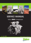
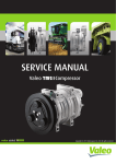
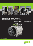
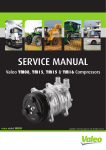
SERVICEMANUAL
ValeoTM55 & TM65Compressors
Copyright © 2014 Valeo Japan CO., LTD. | All Rights Reserved.
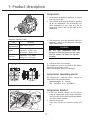
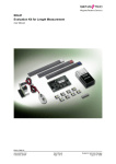
Oil fill-up plug for better
inner oil return
7 double-headed pistons architecture
ensuring smooth and quiet operations
Compact & robust design enabling
easy mounting configurations
Lip type shaft seal providing
ultimate reliability & performance
Light & Compact, Ultimate Reliability, Highest Performance
Foreword
This service manual has been elaborated to help
service personnel to provide efficient and correct
service and maintenance on Valeo TM55 and
TM65 compressors for bus air conditioning.
This manual includes the operation specifications,
procedures for disassembly, reassembly, and
inspection of the compressor.
The contents of the manual, including illustrations,
drawings and specifications were the latest
available at the time of printing.
Valeo Japan reserves the right to make changes in
specifications and procedures at any time without
notice.
VALEO JAPAN CO., LTD.
WARNINGS
The following warning signs are used in this service manual.
These are extremely important to ensure safe operation and to prevent body injuries and
property damage.
They must be fully understood before starting the air conditioner maintenance.
WARNING!
Maintenance must be properly done to avoid serious injury risks.
CAUTION!
Improper maintenance can result in injury or proper damage.
MEANING OF MARKS
The following marks are used in this service manual to facilitate correct air conditioner
maintenance.
Advice
Procedures necessary to ensure the best air conditioner maintenance.
Note
Information to optimize the air conditioning maintenance.
-1-
Contents
1- Product description........................................................................ 3
Compressor speed (rpm)................................................................... 7
Conversion factors.............................................................................. 7
2- Operation precautions................................................................. 15
3- Handling instructions................................................................... 16
Maintenance precautions.................................................................16
Work area...............................................................................................16
Refrigerant handling.............................................................................16
Compressor handling........................................................................17
Compressor removal.........................................................................17
Oil return operation..........................................................................18
Oil handling.......................................................................................18
Oil level at inclination conditions.....................................................19
Front Lifting.......................................................................................19
Lateral Inclination.............................................................................19
Oil contamination.............................................................................20
Oil check............................................................................................20
Replacement of components...........................................................21
Running-in operation........................................................................22
Compressor running-in..........................................................................22
Magnetic clutch running-in...................................................................22
Leak test............................................................................................23
Refrigerant Charging.........................................................................23
Storing a repaired compressor.........................................................23
4- Troubleshooting........................................................................... 24
Compressor troubleshooting.................................................................24
Compressor troubleshooting tree.........................................................24
A/C cycle diagnosis by gauge pressure...............................................27
5- Tightening torques....................................................................... 29
6- Service procedures - Magnetic clutch......................................... 30
7- Service procedures - Shaft seal assembly.................................. 36
8- Service procedures - Cylinder heads........................................... 39
9- Service tools................................................................................. 43
10- Service parts.............................................................................. 53
-2-
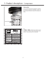
1- Product description - Compressor
Compressor
TM55
MODEL
TM65
TECHNOLOGY
Heavy Duty Swash Plate
550 cc / 33.56 in3 per rev.
DISPLACEMENT
NUMBER OF CYLINDERS
635cc / 38.75 in3 per rev.
14 (7 double-headed pistons)
REVOLUTION RANGE
600-4000 rpm
DIRECTION OF ROTATION
Clockwise viewed from clutch
BORE
38.5 mm (1.52 in)
STROKE
33.7 mm (1.30 in)
SHAFT SEAL
38.9 mm (1.53 in)
Lip seal type
LUBRICATION SYSTEM
Lubrication by gear pump
REFRIGERANT
HFC-134a
OIL (QUANTITY)
ZXL 100PG PAG OIL (1500 cc/0.40 gal) or POE option
Suction: 35 mm (1-3/8 in)
Discharge: 28 mm (1-1/8 in)
CONNECTIONS
Internal Hose Diameter
WEIGHT
Suction: 35 mm (1-3/8 in)
Discharge: 35 mm (1-3/8 in)
18.1kg / 39.9 lbs (w/o Clutch)
341 - 194 - 294 (mm)
13.4 - 7.64 - 9.33 (in)
DIMENSIONS
Length - Width - Height
MOUNTING
Direct (side or base)
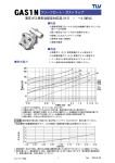
Saturatedcondensingconditions
Valeo TM55 & TM65 Application limits
PSIA
PSIG
o
F
MPaA
MPaG
o
398
384
180
2.75
2.65
82
244
229
140
1.68
1.58
60
125
111
93
0.86
0.76
34
83
68
68
0.57
0.47
20
tc : Condensing temperature
te : Evaporating gas temperature
C
tc
te
-20
-10
10
20
oC
0.03
0.10
0.31
0.47
MPaG
0.13
0.20
0.41
0.57
MPaA
-4
14
50
68
oF
5
14
45
68
PSIG
19
29
60
83
PSIA
Saturatedevaporatingconditions
-3-
1- Product description - Compressor
Nameplate
To ensure that the compressor operates smoothly,
be careful to respect the indications written on
the name plate located on top of the compressor
body.
Name plate
Tip
As TM55 & TM65 compressors have the same
dimensions, the best way to differentiate them
quickly is by referring to the name plate.
COMP. TYPE
TM-XX
PART NO.
ZXXXXXXX X
SERIAL NO. X X X X X X X X XX
ZXL 100PG 1500 cm3
OIL
LEAK TEST
HIGH SIDE 2.9MPaG
LOW SIDE 1.5MPaG
REFRIG.
HFC-134a
M A D E I N J A PA N
-4-
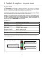
1- Product description - Magnetic clutch
Magneticclutch
VALEO TM55 & TM65 are available either as a compressor and magnetic clutch assembly or as a compressor
body that can be fitted with compatible magnetic clutches. The magnetic clutch design Valeo has been
promoting for more than 20 years is now gradually adopted by major market actors.
Our compressors and magnetic clutches have successfully passed the thousand hours of long validation
tests in Valeo Compressors research center laboratory. Operational excellence was demonstrated during hot
season testing on field under challenging climates in the most stressful conditions.
Being able to rely on our robust magnetic clutch provides the best way to reduce fuel consumption without
using additional unloading devices that decrease significantly the efficiency and durability of the compressor.
The range of Valeo magnetic clutches ensures an unmatched reliability and the longest durability that
perfectly matches the Valeo TM55 & TM65 compressor qualities.
Specifications*
TECHNOLOGY
Electromagnetic single-plate dry clutch
RATED VOLTAGE
24V DC or 12V DC
CURRENT CONSUMPTION
50 W maximum
STATIC TORQUE
250 N·m {25.5 kgf·m, 184 lbf·ft}
DIRECTION OF ROTATION
Clockwise viewed from clutch
WEIGHT
Approx 10~12 kg {22-27 lbs}
V-BELT TYPE
V-groove (A or B) or V-ribbed (PK)
*The specifications may vary with the compressor.
Please also note that the maintenance procedures introduced in this service manual apply only to magnetic
clutches provided by Valeo.
Valeo TM55 & TM65 magnetic clutch
Compact and robust design
Housing mounted magnetic clutch.
Improved robustness to vibration
Bearing and pulley positionned to
reduce efficiently the moment of tilt
Single level or multi-level pulleys
-5-
1- Product description - Connectors
Connectors
1. Fully open the shut-off valve when operating the compressor
• Unscrew the cap.
• Loose the valve spindle seal by 1/4 turn.
• Turn the spindle in the counterclockwise direction until it stops.
The shut-off valve is now fully opened and the service port connector is closed.
• When finished, tighten the valve spindle seal carefully and screw the cap.
1
4
2
1 Valve spindle seal
2 Cap
3
3 Spindle
4 Service port connector
5 Safety devices port
5
2. Open the service port connector when using a gauge manifold
• Turn the spindle in the clockwise direction by 1/2 turn to 1 turn.
The shut-off valve and the service port connector are now opened.
1
4
2
3
1 Valve spindle seal
2 Cap
3 Spindle
4 Service port connector
5
5 Safety devices port
3. Fully close the shut-off valve when removing the compressor
• Turn the spindle in the clockwise direction until it stops.
1
4
2
1 Valve spindle seal
2 Cap
3
3 Spindle
4 Service port connector
5 Safety devices port
5
-6-
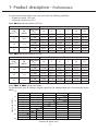
1- Product description - Performance
The performance data below were measured under the following conditions:
• Compressor speed: 1450 rpm
• Suction gas temperature: 20°C
Valeo TM-55 performance data (R134a)
Conditions
Cond.
temp (oC )
Pd
(MPaG)
40
0.91
50
1.21
60
1.58
Cooling Capacity Q and Power Consumption P
Evap temp
(oC )
Ps (MPaG)
Q (kW)
-10
-5
0
5
10
12.5
0.10
14.73
0.15
19.68
0.19
23.88
0.24
29.30
0.32
37.23
0.35
40.31
P (kW)
5.31
5.96
6.39
6.77
7.21
7.36
Q (kW)
12.75
17.52
21.06
25.58
32.97
35.54
P (kW)
5.80
6.59
7.09
7.63
8.32
8.48
Q (kW)
10.53
14.42
17.60
21.39
28.16
30.65
P (kW)
6.28
7.21
7.84
8.52
9.38
9.63
Valeo TM-65 performance data (R134a)
Conditions
Cond.
temp (oC )
Pd
(MPaG)
40
0.91
50
1.21
60
1.58
Cooling Capacity Q and Power Consumption P
Evap temp
(oC )
Ps (MPaG)
Q (kW)
-10
-5
0
5
10
12.5
0.10
17.29
0.15
22.96
0.19
28.21
0.24
33.92
0.32
42.18
0.35
45.71
P (kW)
6.30
7.02
7.53
8.10
8.68
8.90
Q (kW)
15.16
20.21
24.24
29.31
37.58
40.37
P (kW)
6.83
7.76
8.39
9.06
9.90
10.11
Q (kW)
12.66
17.30
20.80
25.28
32.10
34.56
P (kW)
7.35
8.43
9.17
9.95
11.02
11.35
Valeo TM55 & TM65 conversion factors
The performance data at different rotation speed can be approximated with the conversion factors
below.
3.0
P
Conversion factors
2.5
2.0
Q
1.5
1.0
0.5
0.0
0
1000
1450
2000
3000
Compressor speed (rpm)
-7-
4000
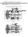
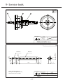
1- Product description - Dimensions
TM55 & TM65 compressors with magnetic clutch
354
253.4
84
∅
∅ 220
∅ 186
165
190
142.4
221.8
12-M12x1.75 Dp.26
140
Sight glass
CB104
CA104
500
56.5
(From field coil)
56.5
111.8
-8-
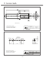
1-Product description - Dimensions
TM55 & TM65 compressors without magnetic clutch
15°
31.3
85.8
110
142.4
1.6
∅ 17.6
162
8-
∅ 27
∅ 32
12-M12x1.75,Dp26 15
85.8
4- ∅ 27
(70)
140
(70)
296.6
194
28
56
56.5
56.5
28
56
Sight glass
-9-
∅ 190
165
84
85
84
165
∅ 65
∅ 50
∅ 47.35
6-M6x1.0,Dp13
PCD ∅ 90
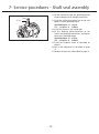
1- Product description - Exploded view
6
27
28
26
25
30
29
22
21
24
3
23
20
7
19
5
16
37
13
17
4
35
2
34
16
1
11
9
18
31
32
33
15
12
14
13
10
8
9
1. Center bolt
2. Armature assembly
3. Adjusting shim
4. Snap ring
5. Pulley assembly
6. Screw
7. Field coil
8. Bolt
9. Gasket
10.Front cylinder head
11.Shaft seal assembly
12.Snap ring
13.O-Ring
14.Gasket
15.Valve plate assembly
16.Suction valve
17.Pin
18.Bolt
19.Cylinder shaft assembly
20.Eye bolt
21.O-Ring
22.Oil filler plug
23.Strainer
24.Gasket
25.Connector
26.Bolt
27.Gasket
28.Plate
29.Plate
30.Bolt
31.Sight glass
32.O-ring
33.Snap ring
34.Valve plate assembly
35.Gasket
36.Gear pump
37.Rear cylinder head
- 10 -
36
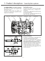
1- Product description - Swash plate system
Swash plate system
Valeo TM55 & TM65 are 14-cylinder swash plate
type compressors. With this type of compressor,
the cylinders and pistons are arranged axially
along the drive shaft.
The pistons operate within the cylinders and
are driven by a swash plate to perform suction,
compression and discharge.
Drive shaft
Radial bearing
The drive shaft, which is driven by the engine
through the magnetic clutch, is equipped with a
swash plate.
The drive shaft is supported by two radial bearings
and two thrust bearings.
The swash plate is rotated by the drive shaft, and
moves the pistons back and forth.
Thrust bearings
Swash plate
Piston
Radial bearing
Piston Drive System
Radial bearing
Thrust bearing
Suction
Suction
Compression
Compression
Piston
The pistons in the cylinders are mounted on the
swash plate through hemispherical shoes.
Each piston has a compression head at each end.
Swash plate rotation results in a reciprocating
piston movement horizontal to the drive shaft.
The cylinders, which are arranged at 51.4° intervals
around the drive shaft, are each divided into 2
chambers, providing 7 front and 7 rear bores.
As each piston performs suction and compression
at either end, the compressor operates as a 14
cylinder compressor.
Shoe
- 11 -
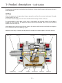
1- Product description - Lubrication
The gear pump situated at the end of the drive shaft draws oil from the oil reservoir and lubricates the parts
of the compressor.
Oilflow
When the compressors start operating, the gear pump draws oil from the reservoir and pumps it through
an oil passage in the shaft.
The oil then flows through ports in the shaft to lubricate the bearings and the shaft seal.
The area between the swash plate and the shoes is lubricated by the splashing action of the oil flowing
through the thrust bearings. The compressor remains constantly lubricated thanks to the oil circulating
together with the refrigerant.
Valeo compressor innovative internal design ensures that almost no oil remains mixed with the refrigerant
that is flushed into the air conditioning system.
Refrigerant itself plays a lubricant role to prevent the compressor to be damaged in case of oil shortage.
Drive shaft
Radial bearing
Shaft seal
Reservoir
Swash plate
Sight glass
Thrust bearings
- 12 -
Radial bearing
Oil passage
Gear pump
Oil passage
1- Product description
Compressor
1. The direction of rotation is clockwise as viewed
from the clutch side.
2. The standard compressor oil charge is specified
for bus air conditioners. The oil quantity may
differ depending on the type and use of
compressor. Please refer to the label on the
compressor.
Operation condition table
Item
Condition
Surrounding
Under 120°C (248°F)
temperature
Minimum: 600 r/min
Speed
Maximum: 4500 r/min
Continuous: 4000 r/min
Maximum: 2.65 MPaG
Pressure
{28kgf/cm², 385 psig}
3. The compressor must be operated under the
conditions shown in the operation condition
table shown at left.
CAUTION!
The A/C cycle components must be
designed so that the pressure in the cycle
does not exceed 2.65 MPaG {28 kgf/cm2,
385 psig}
4. Inclination limit at installation
The compressor must be installed on the vehicle
within the range shown at left.
Front head forward leaning is prohibited.
15˚ 15˚
5˚
Compressor mounting points
The compressor’s mounting points should be
tightened to the specified torque:
Specified torque: 45 ~ 50 N·m
{4.6 ~ 5.1 kgf·m, 33.2 ~ 36.9 lbf·ft}
Compressor bracket
1. Install the bracket securely on the chassis
frame or engine body. As the engine vibrations
may be severe, the bracket and mounting bolts
must be installed securely.
2. Vibration resistance
There must not be any resonance under 250
HZ.
- 13 -
1- Product description
Magneticclutch
1. Voltage
DC 24 V
The terminal voltage of the magnetic clutch
must exceed 21 V.
DC 12 V
The terminal voltage of the magnetic clutch
must exceed 10.5 V.
1 mm
Magnetic clutch
Idle pulley
Drive pulley
2. Ratio of magnetic Clutch to drive pulley
• When the compressor is driven from the pulley
drive of the vehicle, the magnetic clutch to
drive pulley ratio should avoid the range 1:
0.92~1.08 to limit vibration and resonance.
• Compressor speed must not exceed the
specified speed.
CAUTION!
Pulleyratioistheratioofthemagneticclutch
diametertothedrivepulleydiameter.
3. Pulley alignment tolerance is less than 1mm
(0.04 in).
4. Pulley groove: V-groove or V-ribbed.
5. The V-belt tension must be adjusted to the
tension specified by the belt maker.
- 14 -
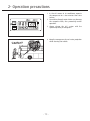
2- Operation precautions
1. In the off season of air conditioner, operate
the compressor for a few minutes from time
to time.
2. Do not drive through water. Water may damage
the magnetic clutch, thus preventing normal
operation.
3. Always charge the A/C system with the
specified quantity of refrigerant.
4. Keep the compressor clear of water projection
while cleaning the vehicle.
- 15 -
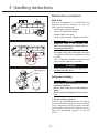
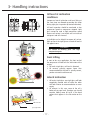
3- Handling instructions
Maintenance precautions
Work area
Because the components of air conditioners are
especially sensitive to moisture, dirt and rust,
always observe the following:
• Work indoors whenever possible
• Select a flat ground work area
• Keep the work area clean
• Select a work area with adequate ventilation.
CAUTION!
Refrigerant itself is not harmful, but
excessive accumulation in a closed area can
cause oxygen deficiency.
• Keep open flame and inflammables away from
the vehicle in which the air conditioner is being
installed.
(Fire is especially dangerous during the gas
leak inspection following installation)
WARNING!
Contact with flame and high temperatures
can generate toxic gases.
Safety glasses
Gloves
Refrigerant handling
WARNING!
Direct contact with refrigerant can cause
frostbite or blindness.
Always wear safety glasses and protective
gloves.
Do not work with refrigerant close to your
face.
1. Do not mistake refrigerants
If an HFC-134a air conditioning system is mistakenly
charged with another refrigerant, serious problems
such as compressor seizing may occur. Therefore,
confirm before charging with refrigerant that the
type of air conditioning system is an HFC-134a
system.
- 16 -
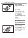
3- Handling instructions
Do not release refrigerant into
the air
FILL
AUTO
2. Do not release refrigerant into the air
Although HFC-134a is not subject to CFC regulations,
it can have effect on global warming and so should
not be released into the air. When removing
refrigerant from the air conditioner system, always
use a refrigerant recovery unit made especially for
HFC-134a.
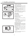
Compressor handling
Recovery unit
Do not strike or unecessarily turn the compressor
upside down. If the compressor is knocked over or
turned upside down during handling or installation,
rotate the armature plate 5 or 6 times to circulate
the oil.
Otherwise, oil in the cylinder during compressor
start-up will cause valve damage and reduce
durability.
Compressor removal
When the compressor is operational
1. Perform the oil return operation (see p.18).
2. Recover the refrigerant from the system using
a refrigerant recovery unit.
3. Remove the compressor.
4. Drain the oil from the compressor and close all
open connections immediately.
5. Check the oil quantity and the degree of
contamination (see p.19).
When the compressor is inoperable
1. Recover the refrigerant from the system using
a refrigerant recovery unit if the shut-off valves
are removed with the compressor.
2. Remove the compressor.
3. Drain the oil from the compressor and close all
open connections immediately.
4. Check the oil quantity and the degree of
contamination (see p.19).
- 17 -
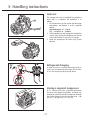
3- Handling instructions
Oil return operation
Compressor oil mixed with refrigerant is circulating
in the air conditioning system.
Perform the oil return operation to return this oil to
the compressor before removing components from
the system.
1. Open the doors and windows and operate the
blower motor at maximum speed.
2. Operate the vehicle engine at idling during at
least 20 minutes.
Note: The maximum amount of oil cannot be
recovered at higher speeds. This operation also
requires a warm ambient temperature.
Oil handling
Oil specification
Use only ZXL 100PG (DH-PS) or POE oil.
Handling precautions
1. The oil must be free from dust, metal filings,
etc.
2. Do not mix oils.
3. The moisture content must not exceed 1,000
ppm. (PAG oil only)
4. The oil easily absorbs moisture when the
container is open. Therefore always seal the
container immediately after use.
Oil quantity inspection
There is no particular need for frequent inspection
or replacement, although it is recommended to
check operating refrigerent pressures and oil levels
at the start of the season.
Please replace the refrigerant and restore the
system oil and refrigerant charge to factory
specifications if:
• the AC system is opened for repair or replacement
of any component (e.g.: evaporator, condenser
or receiver drier)
• any loss of charge - refrigerant or oil - is
detected.
As long as it remains within the range of vision
through the sight glass, the oil quantity is sufficient
Oil level can be read through the sight glass of he
compressor (see on the left).
- 18 -
3- Handling instructions
Oillevelatinclination
conditions
15˚ 15˚
5˚
Compressor lateral inclination and front lifting at
the same time are allowed so consider this factor
during sight glass inspection (distorted indication).
Oil level inspection should be conducted at low
compressor speed or compressor stopped. Sight
glass cannot be used at high compressor speed
because oil surface is not visible and a mixture of
refrigerant and oil is formed.
A flashlight can be helpful to expose oil surface:
light up one of the sight glasses to read oil level at
the opposite one.
CAUTION!
Be careful of rotating parts and high
temperatureparts.
5˚
FrontLifting
In most of bus rear application, the front end of
the compressor is lifted to fit the inclination of the
engine.
1. Oil level at sight glass: oil level is distorted.
2. Oil amount: quantity appears lower than
recommended but the level is actually correct,
you do not need to add more oil.
LateralInclination
15˚
1. Oil level at sight glass: one sight glass will look
completely covered with oil while the other
will look inferior to recommendation or even
empty.
2. Oil amount: in this case, some of the oil is
below oil passage level, therefore you should
consider adding some oil to fill in the dead
volume that appears in the illustration on the
left.
Oil passage
Oil amount below oil
passage level
- 19 -
3- Handling instructions
Oil contamination
Unlike engine oil, no cleaning agent is added to the
compressor oil. Even if the compressor is run for a
long time, the oil never becomes turbid as long as
there is nothing wrong with the compressor or its
method of use. Inspect the extracted oil for any of
the following.
• Increased opacity of the oil.
• Color change to red
• Presence of foreign matter, metal filings, etc.
WARNING!
When system (oil) contamination is
found during compressor replacement,
flush the A/C system with a fluid that
meets SAE J2670 and replace the drier (or
accumulator).
Oil check
The compressor oil must be checked as follows
when being charged into a used system.
1. Perform the oil return operation (p.18).
2. Remove the compressor from the vehicle.
3. Remove the oil filler plug and drain the oil
through the oil filler plug and the high and low
pressure connectors.
4. Check the oil for contamination.
5. Fill the compressor with the specified amount
of oil (p.20)
- 20 -
3- Handling instructions
Specified
charge
1500
Specified
charge
91.5
Amount
recovered
Charging
amount
unit: cm3 & cc
Amount
to remove
from new
compressor
1000 or
more
Same as
recovered
1500 (amount
recovered)
Under
1000
1000
500
Amount
recovered
Charging
amount
unit: cu in
Amount
to remove
from new
compressor
61 or
more
Same as
recovered
61 - (amount
recovered)
Under 61
61
30.5
CAUTION!
The specified oil quantity differs, depending
on the type of air conditioner system. A
label describing the specified quantity is
attached to the compressor. Additionally, all
of the oil cannot be removed when draining
the compressor as some remains as an oil
film on the inside of the compressor and
the system components. Therefore, refer
to the table at left when recharging the
compressor with oil. Excess oil adversely
affects the cooling capacity and the
compressor.
6. Install the oil filler plug and tighten it to the
specified torque.
Specified torque: 15 - 18 N·m
{1.5 - 1.8 kgf·m, 11 - 13 lbf·ft]
CAUTION!
The oil filler plug O-ring must be replaced
with a new one.
Replacement of components
When replacing the component parts of the
system, supply the following amount of oil to the
compressor.
Component mounted
Evaporator
Condenser
Receiver drier
Pipe or hose
Amount of oil
300 cm3 (18.3 cu in)
200 cm3 (12.2 cu in)
100 cm3 (6.1 cu in)
100 cm3 (6.1 cu in)
After installing these component parts, check the
compressor oil. Refer to page 18.
- 21 -
3- Handling instructions
Running-in operation
Whenever moving parts have been replaced, it is
necessary to run-in both the compressor and the
magnetic clutch.
Compressor running-in
Reassembled compressors must be run-in after the
leak test (see next page).
1. Check that the compressor contains the specific
amount of oil.
2. Install the compressor on the test bench.
3. Install the high pressure connector and the low
pressure connector to the ports and tighten the
bolts to the specified torque.
Specified torque: 25 - 32 N·m
{2.5 - 3.3 kgf·m, 18 - 24 lbf·ft}
4. Connect the two connector ports using a flexible
hose.
5. Run the compressor at 1,000 rpm for at least
30 minutes.
6. Replace the oil.
7. Repeat the leak test.
CAUTION!
While the compressor is being run-in in step
5 above, check the outside temperature of
the front head. If the temperature exceeds
80°C (176°F), stop the running-in operation.
Resume the operation when the head has
cooled.
Magnetic clutch running-in
1. Install the clutch on the compressor.
2. Install the compressor on the test bench,
and operate the compressor by running the
system.
3. Maintain the compressor speed at 700 rpm.
Operate the A/C switch through the ON/OFF
cycle at least 50 times (“ON” for 10 seconds
and “OFF” for 10 seconds).
- 22 -
3- Handling instructions
Leak test
The compressor must be checked for refrigerant
leaks after it is repaired. The procedure is as
follows.
1. Fit the connectors to the suction and discharge
connections, and tighten it to the specified
torque.
Specified torque: 25 - 32 N·m
{2.5 - 3.3 kgf·m, 18 - 24 lbf·ft}
2. Fill the compressor with refrigerant through the
suction side, raising the refrigerant pressure to
at least 0.39 MPaG {5 kgf/cm2, 56.3 psig}.
3. Check the compressor for leaks using a leak
detector.
Refrigerant charging
In order to prevent a liquid charge and greatly increase risks of compressor dammage, do not shake
or turn the refrigerant bottle upside down.
Storing a repaired compressor
If it is necessary to store a repaired compressor
for some time before installation, evacuate the
compressor and fill it with dry nitrogen gas through
the suction fitting to raise the pressure to 30 ~ 100
kPa {0.3 - 1.0 kgf/cm2, 4.4 - 14.5 psi}.
- 23 -
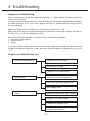
4- Troubleshooting
Compressor troubleshooting
When a trouble occurs during the compressor operation, it is often difficult to pinpoint exactly the
cause of the malfunction.
As long as the compressor maintenance is done correctly, there should not be any problem throughout
the whole vehicle life, but in case it ever happens, we hope this troubleshooting can help you solve
the issue efficiently.
Below are listed most of the troubles you may encounter while the A/C is ON.
Please refer to the compressor troubleshooting tree to localize the malfunction symptom, then look at
the table (p.24 - 25) for the appropriate measure.
Most of the malfunction symptoms can be classified in the following categories:
1. Insufficient cooling capacity
2. Abnormal noise
3. Smoke
In case of insufficient cooling capacity, we recommand that you prepare a gauge manifold to measure
the pressure of both discharge and suction sides (for a detailed diagnosis by gauge pressure, see p.26
- 27).
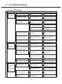
Compressor troubleshooting tree
1. Insufficient cooling capacity
A. Compressor is not running
B. Compressor is running
C. Compressor runs intermittently
2. Abnormal noise
A. Abnormal noise from compressor
B. Abnormal noise from magnetic clutch
C. Belt slipping noise
3. Smoke
A. Magnetic clutch friction surface slipping
B. Magnetic clutch belt slipping
C. Smoke from magnetic clutch
D. Smoke from compressor
- 24 -
4- Troubleshooting
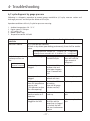
1. Insufficient cooling capacity
Trouble
Compressor is
not running
(No cool blow
coming out)
Symptom
B
C
Compressor
runs
intermittently
(Cool blow
comes out only
from time to
time)
Measure
Magnetic clutch slips when
turning on the A/C switch
Compressor internal part
damage
Replace the compressor
Low pressure cut switch
operate (see p.26 - 27)
Refrigerant shortage
Fix the refrigerant leakage
then fill with refrigerant until
having the right amount
The magnetic clutch slips or
does not engage when the
compressor runs
Lead wire short circuit or
wiring connector not seated
properly
Replace the lead wire if it is
defective
Magnetic clutch damage
Repair or replace the
magnetic clutch
Magnetic clutch air gap too
wide
Adjust air gap or replace
magnetic clutch
Low magnetic clutch voltage
Charge battery
The magnetic clutch engages
but the armature does not
rotate
Belt slipping
Replace the compressor if it
is locked
Belt run off the pulley
Compressor internal part
damage or magnetic clutch
damage
Replace the compressor or
the magnetic clutch
Center bolt is loose / Center
bolt is missing
Bolt drop off/ Armature drop
off
Replace magnetic clutch
Compressor is running
normally
Poor compression
Replace the compressor
No difference of temperature
between discharge side and
suction side (see p.26 - 27)
Refrigerant shortage
Fix the refrigerant leakage
then fill with refrigerant until
having the right amount
The magnetic clutch slips or
does not engage when the
compressor is running
Magnetic clutch friction
surface slipping
Charge the battery or replace
the magnetic clutch
Loose connection of the
magnetic clutch electrical
circuit
Replace the magnetic
clutch after making sure it is
defective
Belt slipping
Magnetic clutch belt slipping
Belt tension readjustment
The magnetic clutch does
not engage
Defective sensor
Replace the sensor after
making sure it is defective
Both discharge and suction
pressures are high
Excess of refrigerant
Reduce the refrigerant
charge until reaching the
right amount
Condenser fan failure
Replace the condenser after
making sure it is defective
The magnetic clutch slips or
does not engage when the
compressor is running
Loose connection of the
magnetic clutch electrical
circuit
Replace the magnetic
clutch after making sure it is
defective
The magnetic clutch does
not engage
Defective sensor
Replace the sensor after
making sure it is defective
A
Compressor is
running
(No cool blow
coming out)
Possible cause
- 25 -
4- Troubleshooting
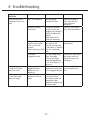
2. Abnormal noise
Trouble
Abnormal
noise from the
compressor
Symptom
Abnormal vibration after
turning on the A/C switch
B
Abnormal
C noise from the
magnetic clutch
Measure
Compressor installation bolt
is loose
Increase tightening torque of
the loose bolts
Wide gap at the attaching
portion between the
compressor and the bracket
Improve the compressor
attaching portion
Abnormal noise from the
compressor body
Compressor body internal
component damage
Replace the compressor
The magnetic clutch has a
backlash and slips
Magnetic clutch damage
Replace the magnetic clutch
Strange noise when the
magnetic clutch engages
Air gap too wide
Adjust air gap or replace
magnetic clutch
Armature slips / does
not engage when the
compressor is running
Magnetic clutch friction
surface slipping
Charge battery or replace
magnetic clutch
Armature does not rotate
when magnetic clutch
engages
Belt slipping
Replace the compressor if
locked. Readjust the belt
tension if the belt is loose
A
Abnormal
noise from the
magnetic clutch
Possible cause
3. Smoke
Trouble
A
Magnetic
clutch friction
surface slipping
Magnetic
clutch belt
slipping
Symptom
The magnetic clutch slips /
does not engage when the
compressor is running
Smoke from
clutch
Smoke from
D the compressor
Measure
Magnetic clutch air gap too
wide
Adjust air gap or replace
magnetic clutch
Low magnetic clutch voltage
Charge battery
Magnetic clutch friction
surface is greasy
Clean friction surface or
replace magnetic clutch
Belt alignment is not correct
Adjust the compressor
installation position
Magnetic clutch belt is
greasy
Clean or replace the belt
Magnetic clutch belt tension
is loose
Adjust belt tension
The magnetic clutch does
not engage
Coil open or shorted
Replace the magnetic clutch
Refrigerant / oil is billowing
out
Refrigerant leaking,
uncoupled piping or piping
burst
Fix the refrigerant leakage
then fill with refrigerant until
having the right amount
The magnetic clutch slips /
does not engage when the
compressor is running
B
C the magnetic
Possible cause
- 26 -
4- Troubleshooting
A/C cycle diagnosis by gauge pressure
Following is a diagnosis procedure to connect gauge manifold to A/C cycle, measure suction and
discharge pressures and analyze the defects of the cycle.
Operation conditions of the A/C cycle for pressure mesuring:
1.
2.
3.
4.
5.
Ambient temperature: 30 - 35 °C
Engine speed: 1.500 rpm
A/C switch: ON
Blower speed: high
Temperature control: full cold
Gauge pressure
indication
Pressure is normal
Cause
Confirmation method
Action to take
A/C cycle operates normally.
If there is any defect (poor cooling performance), there shall be another
cause
Discharge pressure: around 0.9 - 1.6 MPaG (10 - 17 kgf/cm²)
Suction pressure: around 0.03 - 0.10 MPaG (1.3 - 2.0 kgf/cm²)
Both discharge and
suction pressures are
low
Suction pressure
becomes vacuum
Refrigerant shortage
Connect gauge
manifold to cycle
Receiver dryer is
clogged
Temperature difference Replace parts
between inlet and
outlet pipes happens.
Dryer is covered with
frost
Expansion valve is
clogged
Expansion valve was
covered with frost
Clean or replace part
Enclosure leakage
from TXV temperature
sensing tube.
(TXV operates to close
the valve opening)
Outlet side of TXV is
not cooling.
(Low side of gauge
indicates vacuum)
Replace part
Temperature sensing
device at outlet air is
defective
Evaporator becomes
frozen up
Adjust or replace the
part
Refrigerant piping is
clogged or crashed
If any part between
the dryer and the
compressor is clogged
or crashed, the low
side pressure becomes
vacuum
Adjust or replace the
part
- 27 -
Recover refrigerant,
then refill with the
right amount of
refrigerant
4- Troubleshooting
Gauge pressure
indication
Both discharge and
suction pressures are
high
Cause
Confirmation method
Action to take
Excess of refrigerant
Connect gauge
manifold to cycle
Recover refrigerant,
then refill with the
right amount of
refrigerant
Clean up, hand repair
of fin and replacement
Condenser cooling
malfunction
Discharge pressure
is high and suction
pressure is low
Discharge pressure
is low and suction
pressure is high
Condenser becomes
muddy and fins are
clogged and collapsed.
Defect of cooling fan
rotation.
Malfunction of fan
motor for condenser.
Defective refrigerant
Misaligned TXV or
thermal sensing tube
flow control, the
of TXV is not fit on
thermal sensing tube
is not closely in contact
regularly.
(Excess opening of TXV) with the evaporator
pipe
Air mixed in
Just after compressor
refrigeration cycle
stops, discharge
pressure will come
down immediately to
0.19 - 0.29 MPaG (3 - 4
kgf/cm²)
Refrigerant cycle is
Appreciable
clogged between
temperature difference
compressor and
at the clogged location
condenser
Defect of the
Discharge and suction
compressor valve or
pressures balance
gasket
immediately after the
compressor stops.
(Defective compression
of compressor)
- 28 -
Adjustment or
replacement
Evacuate air from cycle,
the charge with the
adequate amount of
refrigerant.
Clean up inside the
cycle or replace the
part
Replace the compressor
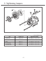
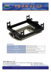
5- Tightening torques
2
5
6
4
1
3
3
Unit: N·m {kgf·m, lbf·ft}
Part
Thread size
Tightening torque
1. Center bolt
M10 x 1.25
25 - 30 {2.5 - 3.1, 18 - 22}
2. Field coil screw
M6 x 1.0
4.2 - 7.2 {0.4 - 0.7, 3.1 - 5.3}
3. Bolt
M10 x 1.5
25 - 32 {2.5 - 3.3, 18 - 24}
4. Oil filler plug
M10 x 1.5
15 - 18 {1.5 - 1.8, 11 - 13}
5. Connector bolt
M10 x 1.5
25 - 32 {2.5 - 3.3, 18 - 24}
- 29 -
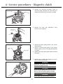
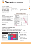
6- Service procedures - Magnetic clutch
Magnetic clutch
Removal
1. Check your armature type (see at left):
• 3-hole type (1)
• 2-way stopper type (2)
3-hole type (1)
2-way stopper type (2)
Armature
holder
2. Remove the armature.
CAUTION!
The armature removal process differs
according to the armature type
• If it is a 3-hole type armature (1)
a. Remove the center bolt using an armature
holder to prevent armature assembly rotation.
Armature puller
assembly
b. Remove the armature assembly using an
armature puller assembly. Remove the shims
from the compressor driveshaft or armature
assembly.
• If it is a 2-way stopper type armature (2)
a. Remove the center bolt using a spanner to
prevent armature assembly rotation.
Spanner
- 30 -
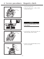
6- Service procedures - Magnetic clutch
b. Remove the armature assembly using an
armature puller. Remove the shims from the
compressor driveshaft or armature assembly.
Armature puller
3. Remove the snap ring (Z0010244) using
external snap ring pliers.
External snap
ring pliers
Snap ring
Center pulley
puller
Pulley puller
4. Position the center pulley puller at the end of
the driveshaft.
5. Attach a suitable pulley puller to the pulley.
Hook the puller claws to the edge of the pulley
as shown.
6. Tighten the center pulley puller bolt to remove
the pulley.
7. Remove the six field coil/compressor screws.
Then remove the field coil.
WARNING!
Removing the pulley will systematically
damage the pulley bearing.
CAUTION!
Do not clip the puller claws into the pulley
groove to prevent pulley groove damage.
CAUTION!
Do not hold the field coil by the harness.
- 31 -
6- Service procedures - Magnetic clutch
Magnetic clutch
Inspection
1. If the contact surface has been damaged by
excessive heat, the armature and pulley must
be replaced.
2. Check the appearance of the pulley assembly. If
the contact surface of the pulley is excessively
grooved due to slippage, both the pulley and
armature must be replaced. The contact surface
of the pulley assembly must be cleaned with a
suitable solvent before reinstallation.
3. Check the field coil for a loose connector or
cracked insulation.
Installation
1. Install the field coil on the compressor (with
the harness on top) and tighten the mounting
screws to the specified torque.
Specified torque: 4.2 - 7.2 N·m
{0.4 - 0.7 kgf·m, 3.1 - 5.3 lbf·ft}
Screws
2. Carefully place the wire harness/strain relief.
Field coil
Press
Pulley assembly
Pulley
installer
• If you are using a press
3. Install the pulley assembly using the pulley
installer and the press.
CAUTION!
Use only a press to install the pulley
assembly. Do not use a hammer. The use
of a hammer may result in damage or
deformation.
- 32 -
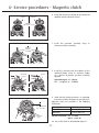
6- Service procedures - Magnetic clutch
3-hole
armature (1)
Armature
holder
Adjusting
shims
2-way stopper
armature (2)
4. Install the armature assembly on the driveshaft
together with the original shim(s) and press it
down.
5. Install the armature bolt and tighten it to the
specified torque using an armature holder
(for 3-hole armature) or a spanner (for 2-way
stopper armature) to prevent armature
assembly rotation.
Specified torque: 25 - 30 N·m
{2.5 - 3.1 kgf·m, 18 - 22 lbf·ft}
Spanner
Adjusting
shims
Gap adjustment
0.3 - 0.7 mm
Thickness
gauge
6. Check that the clutch clearance is as specified.
If necessary adjust the clearance using shim(s).
Adjusting shims are available in the following
thicknesses:
Shim Part No.
Z0010245
Z0010246
Thickness
0.2 mm {0.008 in}
0.3 mm {0.012 in}
Specified clearance: 0.3 - 0.7 mm
{0.012 - 0.028 in}
8. Run in the clutch as described on page 21.
- 33 -
6- Service procedures - Magnetic clutch
• If you are not using a press
3. Install the pulley using a pulley installer
assembly and a spanner.
CAUTION!
If the bolt of the pulley installer assembly
is not screwed into the driveshaft, it may
result in damage.
4. Once the pulley is fixed, loose the collar and
remove the pulley installer assembly.
5. Install the snap ring (beveled edge up) using
external snap ring pliers.
Snap ring
External snap
ring pliers
- 34 -
6- Service procedures - Magnetic clutch
3-hole
armature
6. Install the armature assembly on the driveshaft
together with the original shim(s).
2-way stopper
armature
Adjusting
shims
3-hole armature
2-way stopper armature
7. Install the armature assembly using an
armature installer assembly.
Armature
installer
assembly
3-hole armature
Armature
holder
2-way stopper armature
Spanner
8. Install the armature bolt and tighten to the
specified torque using an armature holder
or a spanner to prevent armature assembly
rotation.
Specified torque: 25 - 30 N·m
{2.5 - 3.1 kgf·m, 18 - 22 lbf·ft}
9. Check that the clutch clearance is as specified.
If necessary adjust the clearance using shim(s).
Adjusting shims are available in the following
thicknesses:
Gap adjustment
0.3 - 0.7 mm
Thickness
gauge
Shim Part No.
Z0010245
Z0010246
Thickness
0.2 mm {0.008 in}
0.3 mm {0.012 in}
Specified clearance: 0.3 - 0.7 mm
{0.012 - 0.028 in}
10. Run in the clutch as described on page 21.
- 35 -
7- Service procedures - Shaft seal assembly
Removal
Bolt
1. Remove the magnetic clutch assembly as
described on page 29.
2. Remove the bolts securing the connectors, and
then remove the connectors and strainer from
the cylinder shaft assembly.
3. Remove the oil filler plug and then drain the
oil.
4. Remove the seven bolts securing the head
using an hexagon (14 mm) wrench.
5. Alternately tap the two projections on the front
head using a remover and a mallet to remove
the front cylinder head.
Tap lightly
Remover
Front cylinder head
6. Remove the snap ring using the internal snap
ring pliers.
Snap ring
Internal snap
ring pliers
Press uniformly
from above
Front cylinder head
Shaft seal
7. Remove the shaft seal assembly using a
remover.
Remover
- 36 -
7- Service procedures - Shaft seal assembly
Inspection
The shaft seal must not be reused.
Always use a new shaft seal when reassembling
the compressor. Ensure that the seal seat is free
from lint and dirt that could damage the shaft seal
lip.
Installation
Press using a press
Remover
Shaft seal
1. Clean the portion of the front cylinder head
where the shaft seal is to be assembled.
2. Assemble the shaft seal on the remover.
3. Coat the shaft seal well with compressor oil
and install the shaft seal in the front cylinder
head with the shaft seal remover.
4. Install the snap ring using the internal snap
ring pliers.
Front cylinder head
Front cylinder head
O-ring
Guide
5. Position the guide on the shaft
6. Coat the new O-ring with clean compressor oil
and install it in the front cylinder head
7. Install the front cylinder head
CAUTION!
Align the pins and tap the head lightly and
evenly with a plastic hammer.
8. Remove the guide
9. Install the seven bolts from the front cylinder
head side and tighten them to the specified
torque:
Specified torque: 25 - 32 N·m
{2.5 - 3.3 kgf·m, 18 - 24 lbf·ft}
Tighten each bolt gradually (in three or more
stages) to ensure the specified torque.
10.Turn the drive shaft 2, 3 times by hand to ensure
that the shaft rotates smoothly.
- 37 -
7- Service procedures - Shaft seal assembly
Oil filler plug
O-ring
11.Fill the compressor with the specified amount
of clean compressor oil through the oil filler.
12.Install the oil filler plug with a new O-ring, and
tighten it to the specified torque:
Specified torque: 15 - 18 N·m
{1.5 - 1.8 kgf·m, 11 - 13 lbf·ft}
13.Install the strainer in the suction port.
14.Fit the blanking plates/connectors to the
suction and discharge connections, and tighten
them to the specified torque:
Specified torque: 25 - 32 N·m
{2.5 - 3.3 kgf·m, 18 - 24 lbf·ft}
15.Install the magnetic clutch as described on
page 31.
16.Run in the compressor as described on page
21.
17.Perform the leak test as described on page 22.
- 38 -
8- Service procedures - Cylinder heads
Cylinder heads (Front & Rear)
Disassembly
Bolt
1. Remove the magnetic clutch assembly as
described on page 29.
2. Remove the four bolts securing the connectors,
and then remove the connectors and strainer
from the cylinder shaft assembly.
3. Remove the oil filler plug and then drain the
oil.
4. Remove the seven bolts securing the heads.
5. Alternately tap the two projections on the front
head using the remover and mallet to remove
the front cylinder head.
Tap lightly
Remover
Front cylinder head
6. Remove the front valve plate assembly and
then the suction valve (in that order).
7. Remove and discard the O-ring from the front
cylinder head.
8. Remove all gasket material from the front
cylinder head and the front valve plate.
Suction valve
Gasket
Valve plate assembly
O-ring
- 39 -
8- Service procedures - Cylinder heads
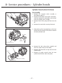
9. Alternately tap the two projections on the rear
head using the remover and mallet to remove
the rear cylinder head.
Tap lightly
Remover
Rear cylinder head
Gasket
Suction valve
O-ring
10.Remove the rear valve plate assembly and
then the suction valve (in that order).
11.Remove and discard the O-ring from the rear
cylinder head.
12.Remove all gasket material from the rear
cylinder head and the rear valve plate.
Valve plate
assembly
13.Remove the gear pump from the rear cylinder
head or the end of the driveshaft.
Gear pump
Rear cylinder head
Inspection
Valve plate
Cylinder head
Check the front and rear valve plates for scratched,
bent or damaged parts.
Inspect both cylinder heads and both valves plates
for nicks or burrs on the sealing surfaces.
Clean both cylinder heads and both valve plates or
replace them if they are cracked or damaged.
Check that there are no clogged passages in the
valve plates.
- 40 -
8- Service procedures - Cylinder heads
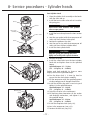
Escape groove
Reassembly
Rear cylinder head
1. Place the cylinder shaft assembly on the bench
with the rear side up.
2. Install the rear suction valve so that it matches
the pins.
CAUTION!
Ensure each valve matches each cylinder
valve escape groove.
3. Install the rear valve plate on the rear suction
valve.
CAUTION!
Do not mistake the front and rear valve
plates.
Gear pump
Rear cylinder head
Gear pump
O-ring
4. Coat the new gasket with clean compressor oil
and install it on the rear valve plate.
5. Coat the new gear pump with clean compressor
oil and install it on the end of the drive shaft.
6. Coat the new O-ring with clean compressor oil
and install it on the rear cylinder head.
7. Install the rear cylinder head.
When positioning the head, ensure the gear
pump is inserted into the hole in the cylinder
head.
Gasket
Valve plate
assembly
Suction valve
- 41 -
8- Service procedures - Cylinder heads
Front Cylinder Head
1. Place the cylinder shaft assembly on the bench
with the front side up.
2. Install the front suction valve so that it matches
the spring pins.
O-ring
CAUTION!
Gasket
Ensure each valve matches each cylinder
valve escape groove.
Valve plate
assembly
Suction valve
Pins
Guide
3. Install the front valve plate on the front suction
valve.
4. Coat the new gasket with clean compressor oil
and install it on the front valve plate.
5. Position the guide on the shaft.
6. Coat the new O-ring with clean compressor oil
and install it on the front cylinder head.
7. Install the front cylinder head.
CAUTION!
Align the spring pins and tap the head
lightly and evenly with a plastic hammer.
Oil filler plug
O-ring
8. Remove the guide.
9. Install the seven bolts from the front cylinder
head side and tighten them to the specified
torque.
Specified torque: 25 ~ 32 N·m
{2.5 - 3.3 kgf·m, 18 - 24 lbf·ft}
Tighten each bolt gradually (in three or more
stages) to ensure the specified torque.
10.Turn the drive shaft 2, 3 times by hand to
ensure that the shaft rotates smoothly.
11.Fill the compressor with the specified amount
of clean compressor oil through the oil filler.
12.Install the oil filler plug with a new O-ring and
tighten it to the specified torque.
Specified torque: 15 - 18 N·m
{1.5 - 1.8 kgf·m, 11 - 13 lbf·ft}
13.Install the strainer in the suction port.
14.Fit blanking plates/connectors to the suction
and discharge connections, and tighten it to
the specified torque.
Specified torque: 25 - 32 N·m
{2.5 - 3.3 kgf·m, 18 - 24 lbf·ft}
15.Install the magnetic clutch (see p.31).
16.Run in the compressor (see p.21).
17.Perform the leak test (see p.22).
- 42 -
9- Service tools
In addition to standard tools, numerous special tools are necessary to service the Valeo TM55 & TM65
compressors. The use of these special tools enables prompt and correct compressor service.
The drawings and the specifications of the service tools listed below are enclosed in the following pages.
Service tools
Item
Name
Picture
Ref.
page
29,32,
34
Application
1
Armature holder
2
Armature installer
assembly
34
To install armature
43-44
3
Center pulley
puller
30
To remove pulley
45
4
Pulley installer
31
To install pulley
45
5
Pulley installer
assembly
33
To install pulley
46-47
6
Cylinder head
remover
35, 38,
39
To remove cylinder head and
cylinder block
48
7
Guide
36, 41
To install shaft seal
48
8
Shaft seal remover
/ installer
35, 36
To remove and insert the
shaft seal
49
9
Armature puller
30
To remove armature
49
10
Armature puller
assembly
29
To remove armature
50-51
- 43 -
To fix armature
Drawing
page
43
9- Service tools
1
2
3
3rd Angle Proj.
Unless otherwise specified,
the edges to be slight chamfering.
Should remove burrs and fluff.
Surface Treatment
Br
Heat Treatment
& Hardness
- -HQF - HTL
HRC40 to 45
1 SS41
2 SS41
3 S45C
Material
Part Name
Armature Holder
1
2
1
2
3rd Angle Proj.
Material
Surface Treatment
Heat Treatment
& Hardness
Material
Part Name
- 44 -
Assy
Armature Installer Assy
Bolt
Collar
9- Service tools
Armature Installer Assy
1
C1
Ø6
C1
Ø 10
( 10.4 )
M14x2.0
M10x1.25
45
6
24
°
42
9
80
Unless otherwise specified,
the edges to be slight chamfering.
Should remove burrs and fluff.
-0.2
12
3rd Angle Proj.
Surface Treatment
Heat Treatment
& Hardness
Material
Part Name
Br
HQ-HQf
HRC40 to 45
S45C
Bolt
Armature Installer Assy
2
( 27.70 )
Ø 15
Ø 22
M14 x2.0
40
24
40
Unless otherwise specified,
the edges to be slight chamfering.
Should remove burrs and fluff.
3rd Angle Proj.
Surface Treatment
Heat Treatment
& Hardness
Material
Part Name
- 45 -
Collar
-0.35
Br
HQ-HQf
HRC40 to 45
S45C
9- Service tools
Section view A-A
3rd Angle Proj.
Unless otherwise specified,
the edges to be slight chamfering.
Should remove burrs and fluff.
Surface Treatment
Heat Treatment
& Hardness
Material
- - -HQ - HTL
HRC40 to 45
S45C
Part Name
Center Pulley Puller
Section view A-A
3rd Angle Proj.
Unless otherwise specified,
the edges to be slight chamfering.
Should remove burrs and fluff.
Surface Treatment
Heat Treatment
& Hardness
Material
Part Name
Pulley Installer
- 46 -
HQ - HTL
HRC58
SK105 (JIS)
9- Service tools
1
2
3
1
Bolt
Spacer
Collar
3
2
3rd Angle Proj.
Material
Surface Treatment
Heat Treatment
& Hardness
Assy
Material
Part Name
Pulley Installer Assy
Pulley Installer Assy
( 13.9 )
M16x2.0
C1
C2
Ø6
Ø 12
M10x1.25
1
4
6
24
5
15
100
12
15
Unless otherwise specified,
the edges to be slight chamfering.
Should remove burrs and fluff.
3rd Angle Proj.
Surface Treatment
Heat Treatment
& Hardness
Material
Part Name
- 47 -
Bolt
-0.25
Br
HQ-HQf
HRC40 to 45
S45C
9- Service tools
Pulley Installer Assy
2
40
A
5
10
1
-0.1
Ø 82.6
+0.2
Ø 58
-0.1
Ø 51
Ø 18
.5
C0
C2
C5
Ø 28.5
Ø 70
.5
±0.2
C0
A
25
Section view A-A
Unless otherwise specified,
the edges to be slight chamfering.
Should remove burrs and fluff.
3rd Angle Proj.
Surface Treatment
Br
HQ-HTL
HRC58
SK3
Heat Treatment
& Hardness
Material
Part Name
Spacer
Pulley Installer Assy
Ø 28
-0.3
( 27.7 )
M16x2.0
20
24
15
Unless otherwise specified,
the edges to be slight chamfering.
Should remove burrs and fluff.
3rd Angle Proj.
-0.35
Surface Treatment
Heat Treatment
& Hardness
Material
Part Name
- 48 -
Collar
Br
HQ-HQf
HRC40 to 45
S45C
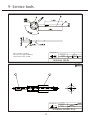
3
9- Service tools
3rd Angle Proj.
Unless otherwise specified,
the edges to be slight chamfering.
Should remove burrs and fluff.
Surface Treatment
Heat Treatment
& Hardness
Material
SK85 (JIS)
Part Name
Remover (for cyl. head)
3rd Angle Proj.
Unless otherwise specified,
the edges to be slight chamfering.
Should remove burrs and fluff.
Surface Treatment
Heat Treatment
& Hardness
Material
Part Name
Shaft Seal Guide
- 49 -
SUS304
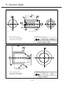
9- Service tools
Section view A-A
3rd Angle Proj.
Unless otherwise specified,
the edges to be slight chamfering.
Should remove burrs and fluff.
Surface Treatment
Heat Treatment
& Hardness
Material
- - -HQ - HTL
HRC40 to 45
S45C
Part Name
( 16.2 )
Remover
C1
R1
R2
Ø7
M12x1.75
5
29
±0.5
60
14
20
Unless otherwise specified,
the edges to be slight chamfering.
Should remove burrs and fluff.
3rd Angle Proj.
Surface Treatment
Heat Treatment
& Hardness
Material
Part Name
- 50 -
Armature Puller
-0.25
Br
HQ-HQf
HRC40 to 45
S45C
9- Service tools
1
2
3
Plate
Pole
Bolt
1
3
2
3rd Angle Proj.
Surface Treatment
Heat Treatment
& Hardness
Material
Part Name
Armature Puller Assy
1
Armature puller assy
6-6
(15)
0°±
2-C1.0
0.1
°
12-C1.0
PC
.1
±0
0
D5
Ø70
2-C1.0
6-M12X1.75
M16X2.0
3rd Angle Proj.
Unless otherwise specified,
the edges to be slight chamfering.
Should remove burrs and fluff.
Surface Treatment
Br
Heat Treatment
& Hardness
Material
Part Name
Plate
- 51 -
S45C
9- Service tools
2
Armature puller assy
(152)
(18)
(12)
R2
R1.5
R
C1.0
M16X2.0
(2)
(13.9)
30°
3rd Angle Proj.
Unless otherwise specified,
the edges to be slight chamfering.
Should remove burrs and fluff.
Ø16
(57)
Ø10
(42)
Ø7
Ø10.5
(35)
Surface Treatment
Br
Heat Treatment
& Hardness
- -HQ - HQf
HRC40 to 45
S45C
Material
Part Name
Pole
3
Armature puller assy
(0.5)
45°
R1.5
Ø5
Ø9.5
(0.5)
(96)
A section detailed view
(9)
(7)
(30)
(20)
(12)
(13.9)
Ø10
A
Ø9.5
(7)
(30)
Ø10
(10/1)
C1.0
M6X1.0
M12X1.75
30°
3rd Angle Proj.
Unless otherwise specified,
the edges to be slight chamfering.
Should remove burrs and fluff.
Surface Treatment
Br
Heat Treatment
& Hardness
Material
Part Name
Bolt
- 52 -
S45C
10- Service parts
1. Compressor body service kits, sets and parts
Item* Part name
OVERHAUL KIT
(O-RING SET + GASKET SET + SHAFT SEAL)
Reference
Quantity
Z0014427
-
12
20
O-RING SET
O-ring body (front & rear head)
O-ring drain
Z0014430
Z0004833
569300-4000
n=2
n=1
13
31
9
GASKET SET
Gasket front head
Gasket rear head
Gasket (bolt) 9 per set
Z0014431
Z0004779
Z0004780
569310-6200
n=1
n=1
n=9
11
SHAFT SEAL (for service)
Shaft seal
Z0007461
n=1
14
30
15
OTHER COMPRESSOR PARTS
Valve plate assy (front)
Valve plate assy (rear)
Suction valve
Z0004775
Z0004777
Z0004774
n=1
n=1
n=1
Reference
Z0011223
Z0011226
Z0011227
Z0011228
Quantity
n=1
n=1
n=1
n=2
*See Product description - Exploded view (p.10)
2. Connector assy (Z0011222) service parts
Item*
24
23
26
25
Part name
Connector (body)
Gasket
Gasket
Bolt
*See Product description - Exploded view (p.10)
3. Oil
Item
-
Part name
ZXL 100PG (250 cc)
Reference
Quantity
569900-0600 250 cc
- 53 -
Remarks
Dis./Suc.
For conn.
For piping
For conn.
VALEO COMPRESSORS - TM55 & TM65 for HFC-134a use
SERVICE MANUAL
Version: WW5565-14011.01EN
Published by: VALEO JAPAN CO, LTD.
Printed in Japan
Copyright 2014, VALEO JAPAN CO, LTD.
For any inquiry regarding the present service manual,
contact us at [email protected]
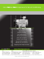
Valeo TM55 & TM65 Compressors for Bus Air-Conditioning.
Valeo TM55 & TM65 Benefits
High reliability
Integration flexibility
Great cooling capacity
Enhanced performance
Lower fuel consumption
Compact & robust design
Improved field serviceability
Reduced noise and vibrations
Staggering value through innovation
Asia
39 Sendai, Kumagaya-shi
Saitama-ken 360-0193 Japan
Phone: +81 (0) 48 539 3800
Fax: +81 (0) 48 539 3843
Email: [email protected]
China
Europe,MiddleEast&Africa Americas
No.2677 Shiji Avenue, Eco. & Tec. Dvt
Zone 130031 Changchun, Jilin PRC
Phone: +86 (0) 431 8499 2025
Fax: +86 (0) 431 8499 2004
Email: [email protected]
8, rue Louis Lormand ZA de l’Agiot
78321 La Verriere, France
Phone: +33 (0) 1 3013 5027
Fax: +33 (0) 1 3461 5898
Email: [email protected]
Copyright © 2014 Valeo Japan CO., LTD. | All Rights Reserved.
2520 Esters Blvd #100
Dallas, TX 75261 United States
Phone: +1 972 456 1077
Fax: +1 972 456 1090
Email: [email protected]