1
G S I G R A I N C O N D I T I O N I N G
Tower Dryer Ops & Service
TOWER DRYER
1
9
9
S Y S T E M S
9
OPERATION AND SERVICE MANUAL
PNEG-526
12', 18', 24' & 30'
DIAMETER DRYER
MODELS
1
Tower Dryer Ops & Service
2
Tower Dryer Ops & Service
TABLE OF CONTENTS
DRYER OPERATION
Safety First..............................................................................................................4
Safety Features............................................................................................................5
Safety Precautions......................................................................................................6
GSI Tower Dryer Cutaway........................................................................................7
Installation Requirements........................................................................................8
Electrical................................................................................................................8
Fuel........................................................................................................................8
Dryer Control Panel ...................................................................................................9
Dryer Start Up.......................................................................................................11
Dryer Shutdown.........................................................................................................13
Electronic Monitoring Control Operation.............................................................14
Turning On The Electronic Monitoring Control System...............................14
The Electronic Monitoring Control System Display Screen...........................14
Setting The Out Of Grain Timer....................................................................15
Setting The Load And Unload Delays............................................................15
Utilizing The Bushel Counter........................................................................15
Modifying The Bushel Per Hour Factor.........................................................15
Displaying The Dryer Hour Meter.................................................................15
Dryer Safety Circuit......................................................................................15
Displaying The Dryer Safety Shutdown Log.................................................15
Electronic Monitoring Control System Messages.........................................15
MAINTENANCE
Pre-Seasonal Inspection And Service...................................................................16
Lubrication Table...........................................................................................16
Seasonal Inspection And Service.........................................................................17
In Case Of Fire..................................................................................................17
End Of Season Service.......................................................................................17
TROUBLE SHOOTING
Trouble Analysis Procedure.................................................................................18
WARRANTY..............................................................................................................23
ELECTRICAL DIAGRAMS
COMPONENT MANUALS
Toshiba Compact Inverter
Maxon Series "NP" & "RG" AIRFLO Burners
Protectofier Service Manual
Honeywell Modutrol IV Motors
Rockwell 121 Regulator
Hansen Transmissions-Service Manual Geared Motors And Gear Units
ASCO Solenoid Valves
FISHER Single And Second-Stage LP-Gas Regulators
Honeywell UDC2000 Mini-Pro Universal Digital Controller Product Manual
Troubleshooting/Service Section
3
SAFETY FIRST
Tower Dryer Ops & Service
SAFETY GUIDELINES
This manual contains information that is important for you, the owner/operator, to know and
understand. This information relates to protecting personal safety and preventing
equipment problems. It is the responsibility of the owner/operator to inform anyone
operating or working in the area of this equipment of these safety guidlines.To help you
recognize this information, we use the symbols that are defined below.
Please read the manual and pay attention to these sections. Failure to read this manual
and its safety instructions is a misuse of the equipment and may lead to serious injury or
death.
This is the safety alert symbol. It is used to alert you
to potential personal injury hazards. Obey all
safety messages that follow this symbol to avoid
possible injury or death.
DANGER indicates an imminently hazardous situation
which, if not avoided, will result in death or serious injury.
WARNING indicates a potentially hazardous situation
which, if not avoided, could result in death or serious
injury.
CAUTION indicates a potentially hazardous situation
which, if not avoided, may result in minor or moderate
injury.
CAUTION used without the safety alert symbol indicates a
potentially hazardous situation which, if not avoided, may
result in property damage.
NOTE indicates information about the equipment that you
should pay special attention to.
4
SAFETY FIRST
Tower Dryer Ops & Service
The GSI Group, Inc.'s principle
concern is your safety and the safety
of others associated with grain handling equipment. This manual was
written with that thought in mind.
We want to keep you as a customer
by helping you understand
safeoperating proceedures, and
some of the problems that may be
encountered by the dryer operator
or other personnel.
As owner and/or operator, it is
your responsibility to know what requirements, hazards and precau-
tions exist, and to inform all personnel associated with the equipment
or who are in the dryer area. Avoid
any alterations to the equipment.
Such alterations may produce a very
dangerous situation, where serious
injury or death may occur.
The GSI Group, Inc. recommends you contact
your local power company and have a representative
survey your dryer installation, so your wiring will be
compatible with their system and you will have adequate power supplied to your unit.
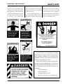
Safety decals should be read and understood by
all people in and around the dryer area. If the following safety decals are not displayed on your dryer, or if
they are damaged, contact The GSI Group, Inc. for
replacement:
The GSI Group, Inc.
1004 E. Illinois St.
Assumption, Illinois 62510
phone: 217-226-4421 fax: 800-800-5329
5
SAFETY PRECAUTIONS
1. Read and understand the operating manual before trying to operate
the dryer.
2. Never operate the dryer while any guards are removed.
3. Power supply should be OFF for service of electrical components. Use CAUTION in checking voltage or other procedures requiring power to be ON.
4. Check for gas leaks at all gas pipe connections. If any leaks are
detected, do not operate dryer. Shut down and repair before further operation.
5. Never attempt to operate the dryer by jumping or otherwise bypassing
any safety devices on the unit.
6. Do not exceed maximum recommended drying temperatures.
7. Keep the dryer clean. Do not allow fine material to accumulate in
the plenum chamber.
Tower Dryer Ops & Service
Use Caution In The
Operation Of This Equipment
The design and manufacture of this
dryer is directed toward operator
safety. However, the very nature of
a grain dryer having a gas burner,
high voltage electrical equipment
and high speed rotating parts, does
present a hazard to personnel, which
can not be completely safeguarded
against, without interfering with efficient operation and reasonable access to components.
Use extreme caution in working
around high speed fans, gas-fired
heaters, augers and auxiliary conveyors.
KEEP THE DRYER CLEAN
DO NOT ALLOW FINE
8. Keep blower drive belts tight enough to prevent slippage.
9. Use CAUTION in working around high speed fans, gas burners, augers
and auxiliary conveyors which START AUTOMATICALLY.
10. Do not operate in any area where combustible material will be drawn into
the fan.
11. Be certain that capacities of auxiliary conveyors are matched to dryer
metering capacities.
12. Clean grain is easier to dry. Fine material increases resistance to airflow
and requires removal of extra moisture.
13. Do not adjust any moving part on the dryer while it is running.
READ THESE INSTRUCTIONS
BEFORE OPERATION AND SERVICE
SAVE FOR FUTURE REFERENCE
6
MATERIAL TO
ACCUMULATE IN THE
PLENUM CHAMBER
OR SURROUNDING THE
OUTSIDE OF THE DRYER
Continued safe, dependable operation of automatic equipment depends, to a great degree, upon the
owner. For a safe and dependable
drying system, follow the recommendations within this manual, and
make it a practice to regularly inspect the operation of the unit for
any developing problems or unsafe
conditions.
Take special note of the safety
precautions listed above before attempting to operate the dryer.
Tower Dryer Ops & Service
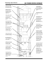
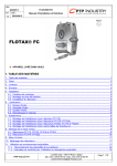
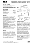
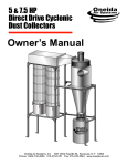
Large wet holding
garner bin is sealed
to help retain grain
dust and bees wings
Stainless steel, roll
formed, exterior
sheeting promotes
long dryer life and
improved dryer
appearance
Heavy-duty overall
construction results
in an extra rigid
structure in a
minimum of ground
space
Inside and outside
safety ladders, cages
and catwalks provide
safe and easy access
to all areas of the
dryer
Reducer cone equalizes
air velocity past
burners for optimum
combustion and
provides step-in access
to burner assembly
Walk-in heat section
provides easy access
for interior cleaning
Recycling heat from
the cooling grain
results in significant
fuel savings
Walk-in cool section
provides easy access
to blowers and
metering system
"Patented" discharge
system provides
simple, uniform
metering and quick
dryer clean out
Industrial quality
components (including Maxon valves
and burners) ensure
years of reliable
service
GSI TOWER DRYER CUTAWAY
12" wide grain
columns and long
grain retention times
result in high quality,
efficiently dried
grain
Grain turners in each
column ensure even
drying
In-line Maxon NP1
series burners
provide even heat
and efficient combustion from either
natural gas or LP
vapor (fuel oil
burners are optional)
Divider hopper
separates the heating
and cooling sections
while preventing
build-up of particulate matter
Internally mounted
tubular centrifugal
blowers deliver high
volumetric airflow to
the pressure heat and
suction cool sections
Internal mounting
provides the added
benefit of ultra quiet
operation as the
surrounding grain
creates a natural
noise barrier
"Patented" Electronic
Monitoring Control
System provides the
most advanced and
reliable dryer control
on the market
Weather-proof
NEMA IV cabinets
and NEMA rated
electrical components ensure safe and
reliable operation in
all conditions
7
DRYER CONTROL PANEL
Tower Dryer Ops & Service
J
A
I
1
H
B
C
E
D
F
G
2
3
5
4
6
13
8
11
7
14
9
10
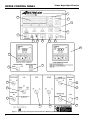
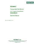
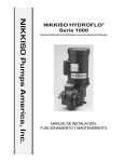
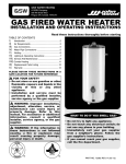
Figure 1: The grain dryer control panel with the Electronic Monitoring Control System in the upper panel.
8
12
Tower Dryer Ops & Service
Dryer Control Panel Featuring The
Electronic Monitoring Control System
1. Electronic Monitoring Control System controls
all the dryer's timing functions and safety circuit
checks. It provides messages and warnings on its
liquid crystal display (LCD).
2. Plenum Temperature Control controls and
indicates drying temperature.
3. Moisture Control Thermostat controls the
metering drum discharge speed automatically when
the MOISTURE CONTROL switch is set to "AUTO".
4. Moisture Control Switch selects automatic or
manual control of the metering drum speed.
DRYER CONTROL PANEL
On choke filled dryers:
In the "AUTO" position only, the dryer will
automatically shut down when the dryer is low on
grain and the OUT OF GRAIN TIMER expires.
In the "MANUAL" or "OFF" position the OUT
OF GRAIN TIMER is disabled.
The LOAD switch is illuminated whenever the lower
grain level indicator senses grain.
9. Fan(s) Switch turns the blower(s) on or off. On
multifan dryers, the blower run through a staggered
startup. The switch is illuminated when all of the
blower airflow switches close indicating that the
blowers are operating correctly.
6. Control Power Switch energizes the control panel
and the Electronic Monitoring Control System.
10. Burner Switch turns the burner on or off. When
the switch is turned on, the dryer automatically goes
through a 60 second purge cycle followed by the
automatic lighting of the burner pilot. The switch
illuminates when flame is sensed at the pilot. After the
pilot flame is established, the Maxon shut off valves
are energized and must be openned manually to
supply gas to the main burner.
7. Outside Light Switch turns the dryer service light
on or off. On "AUTO", the light turns on when the
dryer is running and off when a shutdown occurs.
11. Unload Dry Grain Conveyor Switch turns the
unload conveyor on or off. The switch illuminates
when the conveyor is operating.
8. Load Switch controls the filling of the dryer. The
"MANUAL" position initially fills the dryer. The
"OFF" position turns the conveyor off/shuts the slide
gate. The "AUTO" position enables automatic fill
control and the OUT OF GRAIN TIMER.
12. Metering Drum Switch turns the metering drum
on or off in forward or reverse. The drum will not run
forward unless the unload conveyor is on. The switch
illuminates when the metering drum is discharging
grain.
5. Metering Drum Speed controls the metering
drum discharge speed when the MOISTURE CONTROL switch is set to "MANUAL".
On dryers filled on demand with a conveyor:
In the "MANUAL" or "AUTO" position the fill
conveyor turns on when the dryer is low on grain
and off when the dryer is full.
In the "AUTO" position only, the dryer will
automatically shut down when the dryer is low on
grain and the OUT OF GRAIN TIMER expires.
On dryers filled on demand with a slide gate:
In the "MANUAL" and "AUTO" position the fill
slide gate opens when the dryer is low on grain
and shuts when the dryer is full.
In the "AUTO" position only, the dryer will
automatically shut down when the dryer is low on
grain and the OUT OF GRAIN TIMER expires.
13. Dryer Power Start Button initiates automatic
operation of the dryer. When depressed, the dryer
begins the startup cycle and operates based on the
positions of the selector switches on the control panel.
To control the operation of individual components,
first depress the DRYER POWER START button,
then turn on the individual dryer components as
desired.
14. Dryer Power Stop Switch manually stops all dryer
functions and automatic equipment.
Important: In case of an automatic dryer shutdown,
the DRYER POWER STOP button must be depressed
to reset the dryer control circuit before the dryer can
be restarted.
9
DRYER START UP
1. Prepare dryer for start up
Perform preseason inspection and service as
outlined in the Maintenance Section before
attempting to operate the dryer.
The dryer must have all Pre-Season and
Post-Season maintenance to ensure reliable
operation
Make sure all discharge doors, grain exchanger cleanout doors, heat section door,
louvered cooling section doors, etc. are closed.
Make sure that all personnel are clear of the
dryer and any grain handling machinery.
2. Open main gas valve to dryer.
3. Switch on main breaker to provide electrical
power to the dryer by placing the main circuit
breaker handle located on the dryer power
panel to the "ON" position.
4. Switch on the control panel by turning the
CONTROL POWER selector switch to the
"ON" position. The switch will illuminate
indicating that the control panel has power.
The LCD display screen on the Electronic
Monitoring Control System will light up and
display a copyright message followed a few
seconds later by a second display screen
giving the date and time.
5. Press the RESET button on the Electronic
Monitoring Control System touch panel.
The RESET button MUST ALWAYS be
pressed anytime the Electronic Control System
is initially powered up.
Once the RESET button is pressed, the Electronic Monitoring Control System performs a
dryer safety check. If a fault is found, the
cause of the fault will be displayed on the
LCD screen. Refer to the Troubleshooting
Section for error diagnosis. If no faults are
10
Tower Dryer Ops & Service
found, the dryer can be started and the LCD
will display dryer status.
6. Press the DRYER POWER "START"
button to activate the LOAD, FAN(S),
BURNER, UNLOAD and METERING
DRUM selector switches on the control panel.
7. Start auxiliary equipment needed for filling
dryer. (ie. wet legs, conveyors, etc.)
The burner should be covered before
filling the dryer to prevent accumulation of
foreign material on the Ignitor, Flame Sensor,
and Burner Ports. Foreign material may
interfere with burner operation.
8. Fill the dryer by turning the LOAD selector
switch to the "MANUAL" position. On a
demand fill dryer, the wet conveyor will turn
on / slide gate will open and the dryer will
start filling with grain. Once the dryer is full,
a horn will sound and the wet conveyor will
stop / slide gate will shut. Turn the LOAD
selector switch to the "AUTO" position to
silence the alarm and begin normal dryer
operation. In the "AUTO" position, the dryer
automatically controls the conveyor / slide
gate and the OUT OF GRAIN TIMER is
enabled, allowing automatic shutdown if the
dryer remains low on grain after a preset
period of time. See Electronic Monitoring
Control Section to modify OUT OF GRAIN
TIMER. The LOAD selector switch illuminates whenever the grain level in the dryer
reaches the lower Bindicator, indicating that
the dryer is at operating level.
9. Set drying / plenum temperature on the
PLENUM TEMPERATURE CONTROL.
The upper display indicates the actual plenum
temperature and the lower display indicates
the set point / desired drying temperature. To
Tower Dryer Ops & Service
change the drying temperature press the up or
down keys then press the reset key on the
controller.
Recommended Drying Temperatures
Corn..............................180o to 210oF
Soybeans......................140o to 160oF
Wheat...........................140o to 160oF
Milo..............................160o to 180oF
Barley...........................140o to 160oF
Oats..............................140o to 160oF
10. Start the blower(s) by turning the FAN(S)
selector switch to the "ON" position. The
blower(s) will automatically start. On
multiblower units the Electronic Monitoring
Control System will automatically, start the
blowers sequentially. Once the blower(s) are
up to speed
11. Start the burner by turning the BURNER
selector switch to the "ON" position. The
dryer will automatically go through a 60
second purge period. The amount of time
remaining on the purge cycle will be displayed
on the LCD display screen. After the purge
period the burner pilot will automatically
light. Once the flame sensing circuit on the
dryer senses flame, the light in the BURNER
selector switch will illuminate. If the pilot
fails to light in 60 seconds the dryer will shut
down.
12. Cock and open the Maxon valves. After the
pilot is ignited, the main burner can be lit by
cocking and opening the two Maxon gas
shutoff valves. The main burner will light and
the dryer's plenum temperature will be automatically controlled by the modulating motor
and maintained at the selected temperature.
12.1 Open firing valve (Canadian dryers only)
DRYER START UP
13. Let plenum come up to temperature and
begin drying. Depending upon ambient
conditions, the dryer may take 10 - 20 minutes
to reach the drying temperature
14. Start unload system. Before discharging grain
from the dryer, first make sure all dry legs and
conveyors are operating ahead of the dryer.
On dryers using the "Proof of Auxiliary Unload Running" terminal, the unload conveyor will
not operate unless the auxiliary equipment is running.
Turn the UNLOAD DRY GRAIN CONVEYOR selector switch to the "ON" position to
operate the conveyor leading from the dryer.
The metering drum will not run forward unless the unload conveyor is running, but will run
backward whenever the selector switch is set to
"BACKWARD".
Turn the METERING DRUM selector switch to
the "FORWARD" position to start discharging
grain from the dryer.
15. Set grain discharge rate/Moisture Control
Temperature manually. With the MOISTURE CONTROL selector switch in the
"MANUAL" position, adjust the grain discharge rate using the METERING DRUM
SPEED dial. The LCD displays the current
metering drum RPM or bushels per hour by
pressing the BPH/RPM/TOTAL BU button.
16. Check discharge moisture content after 10
minutes. Take five small samples from the
discharge and mix before taking a moisture
reading.
17. Switch over to Automatic Moisture Control. When the discharge moisture content has
stabilized at the desired amount for 20 to 30
11
DRYER SHUTDOWN
minutes, the dryer may be switched over to
Automatic Moisture Control.
17.1 Note the grain temperature indicated on the
MOISTURE CONTROL THERMOSTAT
(typically 100°F to 120°F) Adjust the set point
on the MOISTURE CONTROL THERMOSTAT to this value using the up or down keys
on the thermostat, then press RESET to lock
in the new set point temperature.
17.2 Turn the MOISTURE CONTROL selector
switch to the "AUTO" position. The MOISTURE CONTROL THERMOSTAT will
automatically adjust the metering drum speed
to maintain the same grain temperature and
grain moisture content.
If the discharge moisture content in
consistently too high or too low, adjust the set
point temperature on the MOISTURE CONTROL THERMOSTAT as follows:
5oF increase = 1 moisture point decrease
5oF decrease = 1 moisture point increase
Allow 30 minutes between adjustments.
After the Automatic Moisture control is
initially set up using the above steps, future
setups will not be required. Following an
extended shutdown, manually operate the
discharge rate from the dryer until the grain
temperature has warmed to the set point
temperature indicated on the thermostat. Then
turn the MOISTURE CONTROL selector
switch to the "AUTO" position for automatic
operation.
18. Shutdown dryer. The dryer will likely have
to be shutdown from time to time. The steps
used to shut it down will depend upon the duration of the shutdown. If the dryer will be
shutdown for 4 hours or less, follow the Short
12
Tower Dryer Ops & Service
Shutdown procedure. For longer shutdowns,
such as overnight, follow the Extended Shutdown procedure
Short Shutdowns - less than 4 hours
For short shutdown periods, the dryer can be
shutdown by pushing the DRYER POWER
STOP button. To restart the dryer, push the
DRYER POWER START button. The Electronic Monitoring Control System will restart
the dryer automatically based on selector
switch settings.
Extended Shutdowns - 4 hours or more
1. Shut off the burner. Turn the BURNER
selector switch to the "OFF" position. All
gas valves will immediately close and the
burner will extinguish.
2. Cool down grain. Continue to operate
blowers for approximately 10 minutes to
cool grain. To avoid overdried grain upon
restarting the dryer, continue to move
grain through the dryer during the cooling
off period.
3. Shut off unload equipment. Turn METERING DRUM and UNLOAD CONVEYOR selector switches to "OFF" position.
4. Shut off blowers. Turn FAN(S) selector
switches to "OFF" position.
5. Shut off control panel. Turn the CONTROL POWER selector switch to the
"OFF" position.
6. Turn off main circuit breaker located on
the power panel.
7. Close main gas valve to the dryer.
Tower Dryer Ops & Service
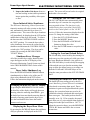
ELECTRONIC MONITORING CONTROL
8. Inspect the inside of the dryer (heat section and cooling section) after operation to
insure against the possibility of hot spots
or fires.
Dryer Initiated Safety Shutdowns
The Electronic Monitoring Control System continuously monitors all safety circuits on the dryer
and automatically shuts the dryer down if a
problem occurs. The cause of the dryer shutdown
will immediately be displayed on the LCD and an
audible horn on the dryer will sound. To silence
the horn turn the CONTROL POWER switch to
the "OFF" position. To restart the dryer after a
safety shutdown, first correct the reason for the
shutdown and then turn the CONTROL POWER
switch to the "ON" position. The dryer can be
restarted by pressing the DRYER POWER
"START" button.
Shutdown Error Messages
All of the possible dryer safety shutdown messages that appear on the LCD display of the
Electronic Monitoring Control System are listed
in the TROUBLESHOOTING section of this
manual.
Dryer Safety Shutdown Log
Press the INCREASE and DECREASE buttons
simultaneously to display a log of the past 25
dryer safety shutdowns on the LCD screen.
Follow the instructions displayed on the screen.
Changing BPH/RPM/Total BU Display
By pressing the BPH/RPM/TOTAL BU button,
the third line of the display will toggle between
showing either the metering drum RPM's , give
the bushel per hour rate that the metering drum is
currently removing grain from the dryer at, or
give the total bushels dried since the bushel
counter was last reset.
Displaying the Dryer Hour Meter
By pressing the INCREASE button the total hours
of dryer operation are displayed on the LCD
screen. The screen will revert back to its original
mode after a few seconds.
Setting the Out Of Grain Timer
The OUT OF GRAIN timer automatically shuts
down the dryer if it remains low on grain for a
user set period of time. This function is only
enabled during dryer operation if the LOAD
switch on the control panel is in the "AUTO"
position. Follow the instructions displayed on the
screen. To change the setting of this timer:
1. Press the OUT OF GRAIN button.
2. Press the MODIFY button.
3. Press the INCREASE or DECREASE
buttons to change the value.
4. Press the ENTER button to accept the new
value.
Setting the Load and Unload Delays
The LOAD delay is used to delay the starting of a
load conveyor or the opening of a slide gate when
the lower Bindicator indicates a low grain level.
The UNLOAD delay is used to delay the stopping
of the unload conveyor after the metering drum
stops to allow the unload conveyor to empty out.
Both the LOAD and UNLOAD delays are set
using the same procedure as the OUT OF GRAIN
timer.
Modifying the Bushel Per Hour Factor
The bushel per hour reading given by the Electronic Monitoring Control System is a calculated
value based on metering drum speed. Due to
variations in grain test weight and unload system
settings, the correction factor may need to be
calibrated so that the calculated and actual grain
flow rates agree. The bushel per hour factor is
normally set at 1.0. If, for example, the actual
grain flow rate is 5 percent higher than displayed,
change the bushel per hour factor to 1.05. To
adjust the correction factor, press the BPH/RPM/
TOTAL BU button and follow the on screen
instructions.
13
MAINTENANCE
Tower Dryer Ops & Service
Pre-Seasonal Inspection and Service
The dryer is made of weather resistant material,
and is designed to require minimum service.
However, each season we recommend the following items be checked before the unit is used, and
any damaged or questionable parts replaced.
These checks will help eliminate possible failures,
and assure dependable operation of the equipment.
1. Shut off electrical power. Open power
box and control box, and inspect for
moisture, rodent damage or accumu
lated foreign material present. Inspect
and tighten any loose terminal connec
tions. Replace any damaged or deterio
rated wiring.
2. Lubricate the blowers and metering
system as outlined in the Lubrication
Table below.
3. Check blower belts for proper tension.
4. Inspect and clean the burner. Visually
check that no holes in the stainless
steel air mixing plates are plugged. If
burner ports are plugged, clear them
with a piece of wire or a drill bit. After
a period of several years, it may
become necessary to drill out the
burner ports to clear away accumulated rust. Use a #47 drill bit to return
burner ports to their original diameter.
5. Check electrical connections at both
the flame rod and spark plug. Clean
spark ignitor.
6. Lubricate linkage on gas modulating
valve. Make sure drain valve in the
fuel train is open at all times except
when the dryer is operational.
LUBRICA
TION TTABLE
ABLE
LUBRICATION
LOCATION
INSTRUCTIONS
TYPE OF LUBRICATION
LUBRICATION
INTERVAL
Metering drum drive shaft
bearing.
Lubricate slowly until lub
shows through seal. Wipe
clean.
High quality, grade #2
lithium based grease.
Beginning of season (annually).
Blower shaft bearings.
Lubricate bottom bearing
slowly counting the grease
gun pumps until lub shows
through the seal. Wipe
clean. Use same number of
grease gun pumps for top
bearing.
High quality, grade #2
lithium based grease.
Every 4 weeks of dryer
operation.
Blower motor bearings.
See motor lubrication procedure below1.
High quality, grade #2
lithium based grease.
Every 2 years (Normal
operation, every 8-10
months
continuous
operaton).
Metering drum drive motor.
See motor lubrication procedure below1.
High quality, grade #2
lithium based grease.
Every 2 years (Normal
operation, every 8-10
months
continuous
operaton).
Metering drum gearbox.
Fill to check plug.
EP Gear Oil (Amoco
Permagear (R) EP (220)) or
equivalent.
Beginning of season.
(Change every 2 years).
1Lubrication of motors--Operate motors for 20 minutes. Clean grease fitting. Remove grease relief plug and using a low pressure grease
gun, pump in the required grease. After relubricating, allow motor to run for 10 minutes before replacing relief hardware. Do not overgrease!
14
Tower Dryer Ops & Service
Seasonal Inspection and Service
1. The hopper access door must be in place at all
times when the dryer is in operation. Before turning
blowers always make sure this door is clamped into
position.
2. Follow lubrication guides as outlined in the
Lubrication Table.
3. Do not let grain fines and dust accumulate inside
the dryer. Bi-weekly if drying most products or
daily if drying milo, clean the cooling chamber floor
of fines and dust. Sweep down the cooling section
sheets if necessary. Fines can be swept into the
hopper. Make sure that the hopper divider that
separates the heat section from the cooling section
remains clean and open.
4. When cleaning dryer, check the grain discharge
area around the metering drum to insure that grain is
flowing freely from each column and that there is
no trash build-up. Also, sweep accumulated dust
off of the metering drum drive motor and gearbox.
5. If undried grain is left in the dryer for more than
a week during the drying season, inspect the plenum
roof to make sure that there is not wet grain sticking
to the roof that could restrict grain flow.
6. When drying dirty corn in high humidity conditions, sludge may build up in the upper outside
sheets of the dryer. This buildup can be removed by
either washing the sheets down with a high pressure
water hose, or by shutting incoming grain, dropping
the grain level to below the plugged area, and then
running the fans and burner to dry the affected area.
Tapping or sweeping the sheets will dislodge debris.
Attempting to sweep off the sheet build-up while it
is still wet will usually plug the sheet more.
In Case of Fire
1. When you first detect a fire, the entire drying
operation should be shut down, including grain flow
into and out of the dryer. The emergency controls
may have already done this. Also, shut off the
electrical and fuel supply to the dryer.
2. Do not try to cool a fire by running the fan(s).
MAINTENANCE
4. Locate the area of the fire.
5. If the fire can be extinguished with a fire extinguisher, water hose or by removing the burning
material, this should be done right away. Watch the
dryer closely for another fire after one has occurred.
6. Emergency discharge slide gates at the bottom of
each column as well as easy access gates located
near the hopper discharge area permit fast dumping
of each individual grain column.
7. A fire extinguisher should be located at or near
the dryer, if a fire seems to be getting out of control
call the fire department.
End of Season Service
1. Empty the dryer at the end of the drying season.
The dryer should not be used for grain storage.
Grain left in there for an extended period of time
can become wet, swell, and spoil. Chunks of
spoiled grain can plug the metering system and
swelled grain places undue stress on the interior and
exterior sheeting of the dryer.
2. Clean out the plenum roof grain cushion and
remove any grain that may be hanging up on the
plenum roof.
3. Make sure the grain exchangers are clean.
4. Clean out the hopper that divides the heat section
from the cooling section.
5. Clean the cooling chamber floor.
6. Remove all grain and trash from the metering
drum floor. This grain can be raked out by hand by
opening the slide gates located in the hopper bottom
of the dryer.
7. Make sure gas supply is shut off to the dryer.
8. Open the gas train drain valve located on the
bottom of the gas train.
9. It is a good practice to cover the burner with a
tarpaulin or plastic to insure a clean burner.
3. Never run grain from the dryer into the elevator
or storage if a fire is known or suspected.
15
TROUBLESHOOTING
Tower Dryer Ops & Service
Trouble Analysis Procedure
A multimeter is required for some
of the following check-out procedures. Before performing any tests,
make certain if the dryer power supply is 3 phase, 230 or 460 volt.
The burner circuit is 120 volts AC
on all standard U. S. production
models.
The control circuit to the motor
starters is 120 volts AC.
The safety circuit is 12 volts D. C.
When checking these circuits, measure voltage between the circuit test
location and to ground.
D. C. circuits should be measured
between the test location and its re-
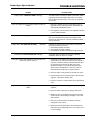
Problem
Control power switch light off.
No display on LCD screen.
Control power light is on, drying mode light is on--load,
fan, burner, unload will not operate.
spective D. C. ground.
CAUTION: When making high voltage
tests with "live" circuits, be extremely
careful. Follow established safety practices. Turn power on for testing only. Do
not attempt to make the dryer operate
by using a jumper wire to bypass a defective safety component.
Possible Cause/Remedy
1. Check that main power and circuit breakers are
turned on. Check for tripped breaker.
2. Check for blown 5 amp fuses.
3. Defective transformer or wiring.
4. Check for a defective power switch.
5. Check wiring between fuses and input/output board.
Refer to wiring diagram for test locations.
1.
2.
3.
4.
Check for a defective power switch.
Check wiring between fuses and input/output board.
Check for 120 volts A. C. between points J9-3 and AC-1.
The display may have a malfunction requiring its replacement.
1. Press the dryer power start button.
2. Refer to the problem listed for load auger, fan heater and
unload auger in the following sections.
Display shows "L1 VOLTAGE LOST" message.
The left circuit breaker located on the input/output board of the
Electronic Monitoring Control System has tripped, or one of the
hardware timers on the Electronic Monitoring Control System has
shut down the dryer.
Display shows "12 VOLT POWER SUPPLY WARNING"
message.
The right circuit breaker located on the input/output board of the
Electronic Monitoring Control System has tripped.
Display shows "_____ OVERLOAD or "____ ____
MOTOR OVL" message.
Indicating either a fan, unload or load motor overload is
tripped.
Blower motor(s) will not start.
16
The thermal overload on the fan motor, load motor, unload
motor or an auxiliary motor has opened indicating an
overloaded motor. (The overloads must be manually reset).
1. Check that the fan circuit breaker and the fan switch are
on. Also, check for defective switch or bad wiring connections.
2. If lighted switch does not light, an air switch needs
adjustment, or the bulb may be burned out.
3. Verify closing of fan motor contactor. Check voltage on
load side of contactor. See appropriate power wiring
circuit diagram for terminal numbers. Inspect contactor
for defective points or a burned out coil.
4. Inspect connections, and check voltage applied to the
motor leads to determine if the motor is defective.
5. If motor starts slowly, check for low voltage during
starting due to excessive voltage drop in power supply
wiring.
Tower Dryer Ops & Service
TROUBLESHOOTING
Problem
Possible Cause
Display shows "LOSS OF FLAME" message.
The flame sensor has failed to detect a pilot flame, indicating that the burner has failed to light, there is a problem
with the flame sensing circuitry or the dryer is not getting
burner fuel.
Burner pilot lights but goes out before Maxon Valves are
cocked.
1. Operator is waiting too long to cock Maxon Valve to
light main burner. (Maxons must be cocked within 60
seconds after establishing a pilot.
2. Pilot regulator pressure needs to be adjusted to achieve
a more stable pilot flame.
Display shows "FAN _____INTERLOCK " message.
Check contactor-wiring on interlock. The contacts on the
side of the specified fan contactor have failed to close
when the fan was turned on. This may indicate a problem
with the contactor.
Display shows "NO AIRFLOW: BLOWER___" message
Indicates the specified blower has failed to show airflow
during the preset period of time.
1. Check airflow switch and tubes.
2. Check wiring to airflow switches.
3. Check belts on blowers, and blower wiring and motors.
Display shows "LOSS OF AIRFLOW" message.
Pilot lights. Cocked and opened the main gas valve, but
main burner will not come on.
The airflow switch contacts have opened, indicating
insufficient airflow for burner to operate.
1. The handle on the Maxon main gas shutoff valves
should offer some resistance when they are opened. If
they don't, check the latching solenoid inside the valve
by removing the cover from the side of the valve
opposite the handle. The solenoid should energize
when a pilot is established. If it does not, check for
faulty electrical connections or a faulty solenoid.
2. Check for water in the gas line by opening drain valve.
3. Check the hand valve in feed back line to the main gas
regulator. It should be partially open.
4. Check for a broken or stuck butterfly in the gas butterfly
valve.
Dryer will not reach operating temperature, or it reaches it
slowly.
1. Low gas pressure. Increase gas pressure on main gas
regulator.
2. Check for water in gas train by opening drain valve.
3. Make sure dryer is completely full of grain by entering
the heat plenum and looking for daylight in one of the
grain columns.
4. Gas parts in burner need to be cleaned. Clean by
drilling with a #47 drill bit.
5. Make sure that the gas butterfly valve is being driven
wide open by the modulating motor. If not, check motor
or motor linkage.
17
TROUBLESHOOTING
Tower Dryer Ops & Service
Possible Cause
Problem
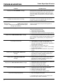
Display shows "OUT OF GRAIN" message.
The dryer has run low on grain, and the out of grain timer
has timed out shutting the dryer down. Check the out of
grain timer setting, and if necessary adjust. Also, before
restarting, inspect load equipment for possible damage or
adjustment.
Display shows "PLENUM HIGH TEMP"
message. Check that columns are flowing.
An over temperature condition has occurred inside the
dryer plenum. This is an adjustable high limit with the
controls mounted in the cooling section.
Display shows "______ ________ HIGH message indicating
the upper, middle, lower or inside high limits have tripped
causing a dryer shutdown.
Check for plugged column, dryer is low on grain or a
column hot spot.
Display shows "FAN _____INTERLOCK " message.
Indicates the specified blower has failed to show airflow
during the preset period of time.
1. Check airflow switch and tubes.
2. Check wiring to airflow switches.
3. Check belts on blowers, and blower wiring and motors.
Display shows "USER UNLOAD IS OFF" message.
1. The user supplied unload that the user has wired to the
dryer component has stopped. This will shutdown the dryer
after 10 minutes. Check auxiliary user supplied unload
equipment.
Dry conveyor will not start.
1. Check that the dry conveyor circuit breaker is on.
2. If the switch does not light, the output power to the
contractor is missing. Check connections, and check to
see if the bulb is burned out.
3. Check that the dry conveyor switch is on.
4. Verify closing of dry conveyor contactor; check voltage
on load side of contactor.
5. Check for any loose wire connections in dry conveyor
circuits.
Display shows "UNLOAD MOT INTERLOCK"
message.
1. Auxiliary contacts on side of unload contact failed to
close when the contactor engaged. Contactor isn't
getting power or has malfunctioned.
Display shows "LOAD MOT INTERLOCK"
message.
1. Auxiliary contacts on side of unload contact failed to
close when the contactor engaged. Contactor isn't
getting power or has malfunctioned.
Display shows "GATE FAILED TO OPEN" message.
Display shows "GATE FAILED TO CLOSE"
Dryer starts losing during capacity.
1.
2.
3.
4.
Check limit switch on close side of gate for malfunction.
Check gate motor for loss of power.
Check for something stuck in gate.
The gate may have taken too long to close.
1.
2.
3.
4.
Check limit switch on open side for malfunction.
Check gate motor for loss of power.
Check for something stuck in gate.
The Gate may have taken too long to open.
1. Dryer not being kept full of grain.
2. Particulate matter has built up on the outside of the
dryer and the dryer needs to be cleaned.
18
Tower Dryer Ops & Service
Problem
TROUBLESHOOTING
Possible Cause
Grain not moving through cloumns.
1. Check that the load breaker and the load auger switch
are turned on.
2. If switch does not light, the output power to the
contactor is missing. Check connections, or if the bulb is
burned out.
3. Verify closing of the wet conveyor contactor. Check voltage on load side of contactor. Inspect contactor for
defective points, or a burned out coil.
4. Inspect connections, and check voltage applied to motor
leads in motor junction box to determine if motor is defective.
Dryer starts losing drying capacity.
1. Dryer not being kept full of grain.
2. Particulate matter has built up on the outside of the
dryer and the dryer needs to be cleaned.
Grain not moving through columns.
1. Check the dryer for fine material buildup inside the
columns.
2. Avoid leaving the dryer columns full for long periods at a
time (2-3 days) while not operating the dryer or during
rainy weather.
3. Empty the dryer. Keep the dryer clean! Do not allow
fine material to gather in the plenum chamber.
4. It may be necessary to open the strike in the
affected columns in half inch intervals.
Uneven drying-Some kernels appear brown while others
are under dried. Uneven heat exiting from dryer columns.
1. Check plenum thermostat temperature setting. Some
varieties of grain are more sensitive to higher operating
temperatures. It may be necessary to lower the plenum
operating temperature to accommodate this.
19
NOTES
Tower Dryer Ops & Service
______________________________________________________________________________________________________
_______________________________________________________________________________________________________
______________________________________________________________________________________________________
__________________________________________________________________________________________________________
___________________________________________________________________________________________________________
__________________________________________________________________________________________________________
________________________________________________________________________________________________________
__________________________________________________________________________________________________________
_________________________________________________________________________________________________________
_______________________________________________________________________________________________________
_________________________________________________________________________________________________________
_______________________________________________________________________________________________________
__________________________________________________________________________________________________
___________________________________________________________________________________________________
_____________________________________________________________________________________________________
____________________________________________________________________________________________________
________________________________________________________________________________________________________
_______________________________________________________________________________________________________
________________________________________________________________________________________________________
_________________________________________________________________________________________________________
________________________________________________________________________________________________________
______________________________________________________________________________________________________
________________________________________________________________________________________________________
____________________________________________________________________________________________________
_______________________________________________________________________________________________________
______________________________________________________________________________________________________
___________________________________________________________________________________________________________
20
Tower Dryer Ops & Service
WARRANTY
THE GSI GROUP, INC. ("GSI") WARRANTS ALL PRODUCTS MANUFACTURED BY
GSI TO BE FREE OF DEFECTS IN MATERIAL AND WORKMANSHIP UNDER NORMAL
USAGE AND CONDITIONS FOR A PERIOD OF 12 MONTHS AFTER RETAIL SALE TO THE
ORIGINAL END USER OF SUCH PRODUCTS. GSI'S ONLY OBLIGATION IS, AND
PURCHASER'S SOLE REMEDY SHALL BE FOR GSI, TO REPAIR OR REPLACE, AT GSI'S
OPTION AND EXPENSE, PRODUCTS THAT, IN GSI'S SOLE JUDGMENT, CONTAIN A MATERIAL DEFECT DUE TO MATERIALS OR WORKMANSHIP. ALL DELIVERY AND SHIPMENT CHARGES TO AND FROM GSI'S FACTORY WILL BE PURCHASER'S RESPONSIBILITY. EXPENSES INCURRED BY OR ON BEHALF OF THE PURCHASER WITHOUT PRIOR
WRITTEN AUTHORIZATION FROM AN AUTHORIZED EMPLOYEE OF GSI SHALL BE THE
SOLE RESPONSIBILITY OF THE PURCHASER.
EXCEPT FOR THE ABOVE STATED EXPRESS LIMITED WARRANTIES, GSI MAKES
NO WARRANTY OF ANY KIND, EXPRESSED OR IMPLIED, INCLUDING, WITHOUT LIMITATION, WARRANTIES OF MERCHANTABILITY OR FITNESS FOR A PARTICULAR PURPOSE OR USE IN CONNECTION WITH (i) PRODUCT MANUFACTURED OR SOLD BY GSI
OR (ii) ANY ADVICE, INSTRUCTION, RECOMMENDATION OR SUGGESTION PROVIDED
BY AN AGENT, REPRESENTATIVE OR EMPLOYEE OF GSI REGARDING OR RELATED
TO THE CONFIGURATION, INSTALLATION, LAYOUT, SUITABILITY FOR A PARTICULAR PURPOSE, OR DESIGN OF SUCH PRODUCT OR PRODUCTS.
IN NO EVENT SHALL GSI BE LIABLE FOR ANY DIRECT, INDIRECT, INCIDENTAL
OR CONSEQUENTIAL DAMAGES, INCLUDING, WITHOUT LIMITATION, LOSS OF ANTICIPATED PROFITS OR BENEFITS. PURCHASER'S SOLE AND EXCLUSIVE REMEDY
SHALL BE LIMITED TO THAT STATED ABOVE, WHICH SHALL NOT EXCEED THE
AMOUNT PAID FOR THE PRODUCT PURCHASED. THIS WARRANTY IS NOT TRANSFERABLE AND APPLIES ONLY TO THE ORIGINAL PURCHASER. GSI SHALL HAVE NO OBLIGATION OR RESPONSIBILITY FOR ANY REPRESENTATIVE OR WARRANTIES MADE
BY OR ON BEHALF OF ANY DEALER, AGENT OR DISTRIBUTOR OF GSI.
GSI ASSUMES NO RESPONSIBILITY FOR FIELD MODIFICATIONS OR ERECTION DEFECTS WHICH CREATE STRUCTURAL OR STORAGE QUALITY PROBLEMS. MODIFICATIONS TO THE PRODUCT NOT SPECIFICALLY COVERED BY THE CONTENTS OF THIS
MANUAL WILL NULLIFY ANY PRODUCT WARRANTY THAT MIGHT HAVE BEEN OTHERWISE AVAILABLE.
THE FOREGOING WARRANTY SHALL NOT COVER PRODUCTS OR PARTS WHICH
HAVE BEEN DAMAGED BY NEGLIGENT USE, MISUSE, ALTERATION OR ACCIDENT.
THIS WARRANTY COVERS ONLY PRODUCTS MANUFACTURED BY GSI. THIS WARRANTY IS EXCLUSIVE AND IN LIEU OF ALL OTHER WARRANTIES EXPRESS OR IMPLIED. GSI RESERVES THE RIGHT TO MAKE DESIGN OR SPECIFICATION CHANGES AT
ANY TIME.
PRIOR TO INSTALLATION, PURCHASER HAS THE RESPONSIBILITY TO RESEARCH
AND COMPLY WITH ALL FEDERAL, STATE AND LOCAL CODES WHICH MAY APPLY
TO THE LOCATION AND INSTALLATION.
21
Tower Dryer Ops & Service
22
Tower Dryer Ops & Service
1004 E. Illinois St., Box 20
Assumption, IL 62510-0020
phone: 217-226-4421
fax: 1-800-800-5329
www.grainsystems.com
August 1998
23