1
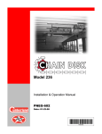
Roof Exhaust Fan
Installation & Operation
Owner’s Manual
PNEG-524
Date: 04-11-07
PNEG-524
Check List
1. All wire connections
2. Tip clearance on blade
3. Fan blade torqued to torque specs
4. Grill guard in place and tight
5. Motor rotation correct
6. Running amperage
7. Vibration
8. All fasteners tight
9. Indicator light
10. All decals and serial number tag
11. Aesthetic appearance
12. Manual in control box
13. Double check parts in hardware boxes
Tester Signature___________________________________________
Date____________________________________
2
PNEG-524 Roof Exhaust Fan
Table of Contents
Contents
Chapter 1 Safety ................................................................................................................................. 4
Roof Damage Warning and Disclaimer ............................................................................... 4
Roof Exhauster Fan Operation ........................................................................................... 4
Safety Alert Symbol ............................................................................................................. 4
Chapter 2 Safety Alert Decals ............................................................................................................ 5
Chapter 3 Pre Installation ................................................................................................................... 6
18" & 24" Roof Fan Package ............................................................................................... 6
Service Information ............................................................................................................. 6
Chapter 4 Specifications .................................................................................................................... 7
Fan Model Specifications for Roof Fans ............................................................................. 7
Chapter 5 Installation ......................................................................................................................... 8
Roof Fan Description .......................................................................................................... 8
18" and 24" Roof Fan Location ........................................................................................... 8
18" Roof Fan Mounting ....................................................................................................... 9
24" Roof Fan Mounting and Assembly of Fan, Adaptor and Rain hood ............................ 10
24" Roof Exhauster Reinforcement Kit .............................................................................. 13
Chapter 6 Parts List .......................................................................................................................... 15
18" Roof Exhauster Parts .................................................................................................. 15
24" Roof Exhauster Parts .................................................................................................. 16
Chapter 7 Electrical Installation ...................................................................................................... 18
Electrical Installation of the Fan ........................................................................................ 18
Electrical Service for Single Phase Operation 230 Volt .................................................... 18
Electrical Service for Three Phase Operation 230 Volt ..................................................... 18
Electrical Service for Three Phase Operation 460 Volt ..................................................... 18
Installation Check .............................................................................................................. 19
Chapter 8 Operating Instructions .................................................................................................... 21
Before Starting Fan ........................................................................................................... 21
Starting the Fan ................................................................................................................. 21
Fan Shut OFF ................................................................................................................... 21
Off Season Operation and Maintenance ........................................................................... 21
Fan Service ....................................................................................................................... 21
Chapter 9 Warranty ........................................................................................................................... 23
PNEG-524 Roof Exhaust Fan
3
1. SAFETY
Roof Damage Warning and Disclaimer
CAUTION!
CAUTION!
Excessive vacuum (or pressure) may
damage roof. Use positive aeration
system. Make sure all roof vents are
open and unobstructed. Start roof
fans when supply fans are started.
Do not operate when conditions exist
that may cause roof vent icing.
DC-969
GSI DOES NOT WARRANT ANY ROOF DAMAGE
CAUSED BY EXCESSIVE VACUUM OR INTERNAL
PRESSURE FROM FANS OR OTHER AIR MOVING
SYSTEMS. ADEQUATE VENTILATION AND/OR
“MAKEUP AIR” DEVICES SHOULD BE PROVIDED
FOR ALL POWERED AIR HANDLING SYSTEMS. GSI
DOES NOT RECOMMEND THE USE OF DOWNWARD
FLOW SYSTEMS (SUCTION). SEVERE ROOF
DAMAGE CAN RESULT FROM ANY BLOCKAGE OF
AIR PASSAGES. RUNNING FANS DURING HIGH
HUMIDITY/COLD WEATHER CONDITIONS CAN
CAUSE AIR EXHAUST OR INTAKE PORTS TO
FREEZE.
Roof Exhauster Fan Operation
Thank you for choosing a GSI product. It is designed to give excellent performance and service
for many years.
This manual describes the operation of the GSI Roof Exhaust Fan. It is designed to take in-bin
air and expel it to the outside.
The principal concern of the GSI Group, Inc. (“GSI”) is your safety and the safety of others
associated with grain handling equipment. This manual is written to help you understand safe
operating procedures, and some of the problems that may be encountered by the operator or
other personnel.
As owner and/or operator, it is your responsibility to know what requirements, hazards and
precautions exist, and to inform all personnel associated with the equipment, or who are in the
area. Avoid any alterations to the equipment. Such alterations may produce a very dangerous
situation, where serious injury or death may occur.
Safety Alert Symbol
The symbol shown is used to call your attention to instructions concerning your personal safety.
Watch for this symbol; it points out important safety precautions. It means “ATTENTION”,
“WARNING”, “CAUTION”, and “DANGER”. Read the message and be cautious to the possibility
of personal injury or death.
WARNING! BE ALERT!
Personnel operating or working around electrical fans should
read this manual. This manual must be delivered with equipment
to its owner. Failure to read this manual and its safety
instructions is a misuse of the equipment.
4
PNEG-524 Roof Exhaust Fan
2. SAFETY ALERT DECALS
The GSI Group, Inc. recommends contacting your local power company, and having a
representative survey your installation so the wiring is compatible with their system, and
adequate power is supplied to your unit.
Safety decals should be read and understood by all people in the grain handling area. The
bottom right decal should be present on the inside bin door cover of the two ring door, 24"
porthole door cover and the roof manway cover.
If a decal is damaged or is missing contact:
The GSI Group, Inc.
1004 E. Illinois St.
Assumption, IL 62510
Ph: (217)-226-4421
A free replacement will be sent to you.
WARNING
Stay clear of rotating
blade. Blade could start
automatically. Can cause
serious injury. Disconnect
power before servicing.
DC-1225
Rotating flighting will
kill or dismember
Flowing material will
trap and suffocate
Crusted material will
collapse and suffocate.
Keep clear of all augers.
DO NOT ENTER this bin!
If you must enter the bin:
1. Shut OFF and lock out all power.
2. Use a safety harness and safety line.
3. Station another person of the bin.
4. Avoid the center of the bin.
5. Wear proper breathing equipment or respirator.
Failure to heed these
warnings will result in
serious injury or death.
DC-GBC-1A
PNEG-524 Roof Exhaust Fan
5
3. PRE INSTALLATION
18" & 24" Roof Fan Package
Figure 3A An 18" Roof Exhaust Fan
18" Roof Fan Package
Roof fan assembly
Bottom mounting flange
Hardware package
Manual PNEG-524
24" Roof Fan Package
Roof fan assembly
Manual PNEG-524
Fan housing top plate
Adaptor-top, right & left side
Rain hood top, right & left side
Hardware package
(4) Template parts
Your model package should contain items shown in above chart.
Note: Before starting the assembly and installation of the roof exhaust fan, check to see
that all items called out on the packing list have been received. In case there are any
shortages, contact your dealer. If there is any damage during shipment, file a claim
with the carrier.
Service Information
Fan model number _____________________________________________________
Fan serial number _____________________________________________________
Bin diameter __________________________________________________________
Grain type ____________________________________________________________
Grain depth __________________________________________________________
Line voltage (measured) ________________________________________________
Dealer purchased from __________________________________________________
Date purchased _______________________________________________________
Fill in the information here for your records. If you have a question regarding your roof exhaust
fan, contact the dealer from whom you purchased the unit. If he is unable to answer your
question, refer to the factory. This information must be available before contacting the dealer or
factory, if service is ever needed.
6
PNEG-524 Roof Exhaust Fan
4. SPECIFICATIONS
Fan Model Specifications for Roof Fans
24" Roof Exhauster Motor Specifications
Exhauster
Model
Fan
Subassembly
Motor
Part #
HP
Phase
Voltage
Enclosure
RPM
Full Load
Amps
TEFC
1725
11.5
MIS-6675-1
MIS-6674-1
MIS-6729
2
1
230
MIS-6675-3
MIS-6674-3
MIS-6686
2
3
208 - 230/460
TEFC
1740
6 - 5.6/2.8
MIS-6675-3E
MIS-6674-3E
MIS-6704
2
3
230/460
XPFC
1740
5.6/2.8
MIS-6675-5
MIS-6674-5
MIS-6800
2
3
575
TEFC
1740
2.2
MIS-6675-6
MIS-6674-6
200-3-50
2
3
380
TEFC
1425
3.5
MIS-6675-6E
MIS-6674-6E
MIS-6796
2
3
380
XPFC
1425
3.6
MIS-6675-7
MIS-6674-7
MIS-6975
2
3
415
TEFC
1425
3.3
All single phase motors and the .5 HP explosion proof three phase motor are supplied with
automatic overload protection. The remaining three phase motors do not have internal motor
protection.
Motors rated as explosion proof (EX PRF) meet class II group F & G of the National Electric Code
(NEC).
Figure 4A Open Area Dimensions and 18" .5 HP
Roof Fan Exhauster Sideview Illustration
PNEG-524 Roof Exhaust Fan
Figure 4B Open Area Dimensions and 24" 2 HP
Roof Fan Exhauster Sideview Illustration
7
5. INSTALLATION
Standard electrical safety practices and codes should be used when working with a fan. Refer
to the National Electric Code Standard Handbook by the National Fire Protection Association. A
qualified electrician should make all wiring installations.
ALWAYS DISCONNECT AND LOCK OUT POWER BEFORE
WORKING ON OR AROUND FAN
Roof Fan Description
GSI roof exhaust fans are designed to mount on structures with sloping roofs, and with a flat roof
surface at least as large as illustrated in Figure 4A & Figure 4B on page 7. The fans will mount
between the ribs of standard tapered roof sheets on round steel bins without cutting the ribs,
which keeps the strength of the roof sheet intact. The 18" .5 HP roof fan is shipped completely
assembled, and will mount on a roof slope of 30 degrees. The 24", 2 HP roof fan is shipped with
the roof adaptor and rained unassembled, and it is also designed to mount on a 30 degree roof
slope.
18" and 24" Roof Fan Location
The roof fans should be equally spaced on the bin roof circumference. When installed, the roof
fan should be positioned as far up the roof slope as the tapered ribs of the bin roof sheet will
allow.
The roof fan location should be selected to provide a rigid mounting for the fan. For bins
with an inner roof structure, the roof fan should be anchored to the inner roof structure.
8
PNEG-524 Roof Exhaust Fan
5. INSTALLATION
18" Roof Fan Mounting
The roof fan can be installed in the roof sheet before assembling the roof, or after the roof is
assembled. Locate roof fan so that inner roof structure does not interfere with installation.
The fan is secured by bolts that must be fastened from the inside of the bin roof, and therefore
the assembly should be made before the side walls are erected.
1. Using the loose flange from the fan assembly as a template, position the desired roof fan
location, allowing for 1" minimum between the roof sheet rib and the flange (See Figure 5A).
Mark the sixteen (16), 3/8" mounting holes, and elliptical fan mounting hole.
2. Drill the sixteen (16), 3/8" holes and cut out the elliptical hole. Use the caulk provided, which
is specified as a seal for metal sheets in an outdoor application, and apply along the in side
edge of the drilled holes on the bin roof sheet (See Figure 5A).
Figure 5A The 18" Template Location on the Roof Sheet (Left), and
the Caulking Location on the Roof Sheet (Right).
3. Place the roof fan into the elliptical hole from the outside of the roof sheet inward. On the
side of the roof sheet that will be inside the bin, position the loose mounting flange over the
fan tube. Using the sixteen (16) 5/16" x 3/4" bin bolts with the neoprene washer head to the
outside of the bin, secure the fan, roof sheet and flange with the 5/16" nuts provided.
(See Figure 5B).
Figure 5B The 18" Roof Exhauster Fan in Relation to the Roof Sheet.
PNEG-524 Roof Exhaust Fan
9
5. INSTALLATION
24" Roof Fan Mounting and Assembly of Fan, Adaptor and Rain Hood
The roof fans, adaptor and rain hood can be installed in the bin roof sheet before assembling the
roof or after the roof is assembled. The fan is secured by bolts that must be fastened from the
inside of the bin roof, so the assembly should be made before the sidewalls are erected.
1. Assemble the roof sheet mounting template as shown in Figure 5C.
Figure 5C 24" Roof Fan Template Placement on the Roof Sheet.
Figure 5D 24" Roof Fan Adaptor and Template Parts Breakdown.
2. Place the roof sheet adaptor mounting template at the appropriate location of the roof fan.
Move the template as far up the roof sheet as possible, but allow for 1" minimum clearance
between the roof sheet rib and bottom of the template on each side.
10
PNEG-524 Roof Exhaust Fan
5. INSTALLATION
3. Drill two corner holes and bolt template in place.
4. Drill the remaining 11/32" mounting holes identified on the template.
Figure 5E The Rainhood Preassembly.
5. Mark a cutting line 3/4" inside the template. Then remove template. Drill through the mark,
cutting a hole in the roof sheet (See Figure 5F).
6. Preassemble the adaptor section parts of the roof fan. Loosely bolt the adaptor left side and
right side to adaptor top. On all components, bolts are to be installed with the head on the
fan housing exterior.
7. Caulk along the bolt hole line where the adaptor flange will mount to the roof sheet.
8. Bolt the adaptor section to the roof sheet along with the support angles MIS-6703 (template)
under the roof sheet (See Figure 5G). Tighten the adaptor to the roof sheet with template
bolts.
Figure 5F The Cutline for Roof Sheet Adapter.
PNEG-524 Roof Exhaust Fan
Figure 5G The 24" Roof Fan Adaptor on Roof
Sheet with Template Bolting Underneath.
11
5. INSTALLATION
9. Form a lip up around the inside of the adaptor opening by peening up the edge of the roof
sheet extending past the inner edge of the roof adaptor.
10. Loosely bolt the rainhood top plate, rainhood right side and rainhood left side together.
11. Bolt the fan housing to the adaptor (See Figure 5H).
Figure 5H The 24" Roof Fan Exhauster and Rainhood.
12. At this time the optional 90° deflector may be preassembled.
13. Bolt deflector assembly to MIS6674 sub-assembly for noise deflection. (See Figure 5I).
Figure 5I The 24" Roof Fan Exhauster with Optional 90° Deflector.
14. Bolt rainhood to fan housing or optional 90° deflector if installed.
15. Support optional 90° deflector adequately down to bin roof structure to prevent exhauster
or roof damage due to flexure of deflector and exhauster.
16. The roof fan location should be selected to provide a rigid mounting for the fan. For
bins with an inner roof structure, the roof fan should be anchored to the inner roof
structure.
17. The fan housing top plate is provided for access to the motor for electrical installation, and
a knock out is provided in the fan side for the wire access. Depending on when you have
your electric connections made, the motor could be wired before Step 12 or the fan could
be wired later by removing the fan housing top plate.
12
PNEG-524 Roof Exhaust Fan
5. INSTALLATION
24" Roof Exhauster Reinforcement Kit
Figure 5J
1. Refer Page 11 for the 24" roof adaptor template and mounting, and the 30° Roof Manual
PNEG-030 for the roof channel assembly.
2. Install the roof support channels in the ribs of the upper panel where the exhauster is to be
mounted.
3. Install the template and cut exhauster parts as specified on Page 11.
4. Utilize the upper MIS-6811 and lower MIS-6805 reinforcement supports to support the
exhauster. Mount reinforcement under the top support plate MIS-6706 and bottom support
plate MIS-6707 on the bottom surface of the roof panel.
5. After placing the supports, field drill the attachment clip at the required locations in channels
CRP-4793.
6. Some field cutting or bolting of components may be necessary due to variables in the roof
exhauster mounting equipment.
7. The MIS-6804 is designed primarily around mounting into the upper roof of a GSI
commercial bin/silo. Field fabrication of supports may be necessary in other brands of
bins/silos.
8. A pair of adjustable brace assemblies are included in this kit to brace the exhauster unit to
the roof ribs on the upper side of the roof. Attach the brace to the roof exhauster unit and
then attach the other end to a roof rib (via a 5/16" bolt). This should attach to the exhauster
near the rainhood mounting angle point.
9. The adjustable brace consists of one center tube (LS-6615) and two end tubes (LS-6616).
The end tubes go inside the center tube and attach one end tube to the top of the extension
rail. Adjust the other end tube so the bottom of the flattened tube reaches the roof rib. Field
drill four 5/16" holes through both center and end tubes and bolt together using
1/4" x 1.1/2" bolts and nuts. This will keep the adjustable brace from slipping.
PNEG-524 Roof Exhaust Fan
13
NOTES
14
PNEG-524 Roof Exhaust Fan
6. PARTS LIST
18" Roof Exhauster Parts
Figure 6A 18" Roof Exhauster Parts Breakdown.
18" Roof Exhauster Parts
Ref #
Part #
Description
Qty
1
F-942
Control box lid
1
2
FH-4429-1
Lid clamp
2
3
F-6864
Control box wrapper
1
4
MIS-6680
18" exhauster weldment
1
5
F-6701
Motor support bracket
1
6
F-953
Fan grill guard
1
7
MIS-6689
18" fan blade
1
8
MIS-6688
.5 H. P. motor
1
9
MIS-6679
Mounting Flange
1
PNEG-524 Roof Exhaust Fan
15
6. PARTS LIST
24" Roof Exhauster Parts
Figure 6B
16
PNEG-524 Roof Exhaust Fan
6. PARTS LIST
24" Roof Exhauster Parts
Ref #
Part #
Description
Qty
1
MIS-6664
Adaptor top plate
1
2
MIS-6666
Exhauster adaptor left panel
1
3
MIS-6665
Exhauster adaptor right panel
1
4
MIS-6686
2 H. P. motor (See Chart Below)
1
5
MIS-6660
Exhauster housing right side
1
6
MIS-6706
Top support plate
1
7
MIS-6703
Support angles
2
8
MIS-6707
Bottom support plate
1
9
MIS-6671
Motor support plate
1
10
MIS-6672
Motor support channels
2
11
MIS-6670
Support plate
1
12
MIS-6687
24" fan blade (See Chart Below)
1
13
TFH-2016
Venturi
1
14
F-954
Fan grill guard
1
15
MIS-6662
Venturi mounting plate
1
16
MIS-6667
Weather hood right panel
1
17
MIS-6668
Weather hood panel
1
18
MIS-6669
Weather hood top
1
19
MIS-6659
Exhauster housing left side
1
20
MIS-6663
Exhauster housing top plate
1
24" Roof Exhauster Parts
Exhauster
Model
Fan Subassembly
Fan
Blade
Motor
Part #
HP
Phase
Voltage
Enclosure
RPM
Full
Load
Amps
Shaft
Size
MIS-6675-1
MIS-6674-1
MIS-6955
MIS-6729
2
1
230
TEFC
1725
11.5
1.125
MIS-6675-3
MIS-6674-3
MIS-6687
MIS-6686
2
3
208-230/
460
TEFC
1740
6-5.6/2.8
0.875
MIS-6674-3E MIS-6687
MIS-6704
2
3
230/460
XPFC
1740
5.6/2.8
0.875
MIS-6675-3E
MIS-6675-5
MIS-6674-5
MIS-6687
MIS-6800
2
3
575
TEFC
1740
2.2
0.875
MIS-6675-6
MIS-6674-6
MIS-6687
200-3-50
2
3
380
TEFC
1425
3.5
0.875
MIS-6796
2
3
380
XPFC
1425
3.6
0.875
MIS-6975
2
3
415
TEFC
1425
3.3
0.875
MIS-6675-6E
MIS-6675-7
MIS-6674-6E MIS-6687
MIS-6674-7
MIS-6687
PNEG-524 Roof Exhaust Fan
17
7. ELECTRICAL INSTALLATION
Electrical Installation of the Fan
The electrical installation must be performed by a certified electrician in accordance with the
appropriate national and local electrical codes.
WARNING
ANY VIOLATION OF ELECTRICAL WIRING CODES COULD JEOPARDIZE THE
AIRSTREAM WARRANTY.
Check the type of electrical service present, and make sure the fan to be wired is manufactured
to operate on the electrical service. The table on page 7 entitled “Fan Model Specifications”
indicates the electrical service the fan is designed to utilize in the column labeled “Motor Phase
and Voltage”. The electrical service must match this specification.
The components to connect the electrical service to the fan need to be sized for the electrical
service present. The charts below illustrate the sizing information for single phase 230 volt, three
phase 230 volt and 460 volt respectively. Use the appropriate information and size the following
electrical service components:
Electrical Service for Single Phase Operation 230 Volt
Motor
H. P.
Range
Transformer Size
(Note B) (Minimum)
0.5
2.0
Copper Wire Size for Distance-Motor to
Disconnect in Feet up to:
0' - 50'
100'
200'
300'
Fusetron or
Equivalent Time
Delay Fuse AMP
1.0 KVA
14
14
12
10
10
3.5 KVA
12
10
6
5
30
Electrical Service for Three Phase Operation 230 Volt
Copper Wire Size for Distance-Motor to
Disconnect in Feet up to:
Motor
H. P.
Range
Transformer Size
(Note B) (Minimum)
0' - 50'
100'
200'
300'
Fusetron or
Equivalent Time
Delay Fuse AMP
0.5
1.0 KVA
14
14
14
14
10
2.0
3.5 KVA
14
12
10
8
15
Electrical Service for Three Phase Operation 460 Volt
Copper Wire Size for Distance-Motor to
Disconnect in Feet up to:
Motor
H. P.
Range
Transformer Size
(Note B) (Minimum)
0' - 50'
100'
200'
300'
Fusetron or
Equivalent Time
Delay Fuse AMP
0.5
1.0 KVA
14
14
14
14
10
2.0
3.5 KVA
14
14
12
12
10
Transformer
The transformer size for the fan only is indicated in a KVA rating. Example: For a 24" fan the first
chart would be used. The KVA rating for the 2 horse power motor is 3.5 KVA. This KVA rating is
for the fan only. Your electrician will need to add the KVA requirements for the other electrical
components of the system in sizing the transformer.
18
PNEG-524 Roof Exhaust Fan
7. ELECTRICAL INSTALLATION
Fan Disconnect
A disconnect for the fan needs to be sized to handle the recommended fusetron size.
Example: For a 24" fan the first chart on Page 17 would be used, and the fusetron size is 30
AMP. Install the fusetron recommended in the disconnect. A circuit breaker can be used,
however, the circuit breaker or any fuse used must be a time delay type to allow the initial starting
inrush current to the fan.
Conductor Size for the Fan Disconnect to Fan Wiring
The conductor size for the fan needs to be sized according to the distance between the fan and
disconnect. Example: For a 24" fan located 200' from the disconnect use the first chart
on Page 17 to determine the conductor size to be a 14 AWG. The proper size wiring must be
used to make sure a voltage drop does not occur.
Fan Motor Controller
Size the fan motor controller according to the motor ratings for a convenient control location as
follows:
Motors with internal overload protection will require a magnetic contactor to control fan
operation. Motors without overload protection will require a magnetic starter with overload
protection to control fan operation.
Single Phase
A 3-wire system should be provided for fans to be operated on single phase power. The three
wires consist of the two current conductors and a ground. The current carrying conductors are
wired per the diagram on the motor. The ground is secured to the motor frame. On 2 HP
explosion proof motors thermostat wires are provided with the motor, and must be connected to
the fan motor magnetic controls.
Three Phase
A 4-wire system should be provided for fans to be operated on three phase power. The four wires
consist of three current carrying conductors, and a ground. The current carrying conductors are
wired per the diagram on the motor. The ground is secured to the motor frame. On 2 HP
explosion proof motors thermostat wires are provided with the motor, and must be connected to
the fan motor magnetic controls.
When installing electrical service for explosion proof motors make sure all conduit and
connectors exposed to the conditions of the motor are rated for the Class II group F and G
location of the motor.
Installation Check
When the fan is completely assembled and wired the unit needs to be checked for proper
rotation. Provide power to the fan controls and start the fan momentarily. Make sure the fan blade
rotates to exhaust air from the bin. If the blade is rotating the wrong direction, have your
electrician correct as follows:
Single Phase System
With the power OFF at the fan disconnect, the motor lead wires at the fan motor need to change
as indicated on the motor to reverse the blade rotation. The unit then needs to be rechecked for
proper rotation.
PNEG-524 Roof Exhaust Fan
19
7. ELECTRICAL INSTALLATION
Three Phase System
With the power OFF at the fan disconnect, exchange the location of the current carrying
conductors at terminal L1 and L3 (See Figure 7A) of the magnetic controls. The unit will then
need to be rechecked for proper rotation.
Figure 7A Connecting the Fan Rotation for Three Phase.
Always check current local, state and national codes on electrical requirements before installing
any electrical equipment.
Transformer size is based on the current draw from the fan only. Your electrician will need to add
the KVA requirements for the other components of the system in sizing the transformer.
Copper wire (rated 75°F) is sized for the fan service. The wire size from the transformer to the
disconnect service will be determined from the fan, and the other electrical equipment
requirements.
Figure 7B 24" Roof Fan Exhauster with the Rain hood in Place.
20
PNEG-524 Roof Exhaust Fan
8. OPERATING INSTRUCTIONS
Before Starting Fan
When starting the fan for the first time, check the following:
1. With the power OFF, rotate the fan blade to make sure it revolves easily, and does not rub
on the venturi or fan tube.
2. Check all the fasteners to make sure they are tight. If any are loose, check for proper
clearance and retighten.
3. With the power OFF, check all electrical connections to make sure they are tight. Inspect
the current carrying wires to make sure they are not grounded. Make sure the fan and
disconnect are grounded. All control enclosure covers and access doors should be secured
in place.
4. Refer to the wiring diagram on the motor, and make sure the motor is wired correctly.
Starting the Fan
The roof exhaust fans should operate anytime the supply fans operate. The roof fans can
operate independently of the supply fans just to provide ventilation of the attic space, but this
requires that vents be used in the roof to provide an open area.
18" fan............4 square feet per fan
24" fan...........10 square feet per fan
Fan Shut OFF
When shutting the fan down for the season, shut OFF the power at the fan disconnect rather than
at the fan controls to provide additional protection from unauthorized personnel operating the
fan, and potential damage to the fan from a lightning strike.
Off Season Operation and Maintenance
During the off season, the fan blade should be allowed to turn freely. The fan should operate for
approximately 30 minutes every three weeks. This keeps the fan lubricant more evenly
distributed within the bearing cavity, and dries out any condensation that could be in the motor.
Fan Service
When servicing the fan, switch power OFF at the fan disconnect switch. Activate power only
when a check is made. The following items will help you to pinpoint a possible malfunction of the
fan unit and explain the corrective action to take.
If the motor controller is turned ON and nothing happens, check the following:
1. Make sure power is available to the fan unit.
2. Check the motor thermostat (if present) to determine if the thermostat is open or closed. If
the thermostat is open, take the motor to your local authorized service center. When
checking the thermostat, make sure the motor has time to cool, if hot.
3. If power is available to the motor and it does not run, remove the motor and take it to an
authorized motor service center for repair or replacement.
PNEG-524 Roof Exhaust Fan
21
8. OPERATING INSTRUCTIONS
If the fan just hums when turned ON, check the following:
1. Check to make sure that all leads of your power source have voltage present. If fan unit is
not receiving power on all leads, check for a blown fuse, broken wire or loose connection.
2. Check to see that all contact sets are closing. If one leg of the supply voltage is not available
to the motor it will hum.
3. If power is available at all motor leads, and the motor still hums, it should be taken to an
authorized service center for repair or replacement.
If the fan starts and operates for awhile and then shuts OFF, check the following:
1. Check the supply voltage. Voltage should be within +/-10% of rated voltage. For example,
a motor rated at 230 volt should operate in a voltage range of 207 to 253 volt.
2. Check the supply wire size required for the fan unit.
3. Check the load on the main circuit to make sure other items on it are not overloading the
fan circuit.
4. Check the amperage of the fan, if the unit is pulling above name plate amperage, take the
motor to an authorized service center.
22
PNEG-524 Roof Exhaust Fan
9. WARRANTY
Warranty
THE GSI GROUP, INC. (GSI) WARRANTS ALL PRODUCTS WHICH IT MANUFACTURES TO
BE FREE OF DEFECTS IN MATERIAL AND WORKMANSHIP UNDER NORMAL USAGE AND
CONDITIONS FOR A PERIOD OF 12 MONTHS AFTER RETAIL SALE TO THE ORIGINAL
END USER. THE PURCHASER’S SOLE REMEDY AND GSI’S ONLY OBLIGATION SHALL BE
TO REPAIR OR REPLACE, AT GSI’S OPTION AND EXPENSE, PRODUCTS THAT, IN GSI’S
SOLE JUDGMENT, CONTAIN A MATERIAL DEFECT DUE TO MATERIALS OR
WORKMANSHIP. ALL DELIVERY AND SHIPMENT CHARGES TO AND FROM GSI’S
FACTORY WILL BE PURCHASER’S RESPONSIBILITY. EXPENSES INCURRED BY OR ON
BEHALF OF THE PURCHASER WITHOUT PRIOR WRITTEN AUTHORIZATION FROM AN
AUTHORIZED EMPLOYEE OF GSI SHALL BE THE SOLE RESPONSIBILITY OF THE
PURCHASER.
EXCEPT FOR THE LIMITED WARRANTY EXPRESSED ABOVE, GSI MAKES NO FURTHER
WARRANTY OF ANY KIND, EXPRESS OR IMPLIED, INCLUDING, WITHOUT LIMITATION,
WARRANTIES OF MERCHANTABILITY OR FITNESS FOR A PARTICULAR PURPOSE OR
USE IN CONNECTION WITH (I) PRODUCT MANUFACTURED OR SOLD BY GSI OR (I) ANY
ADVICE, INSTRUCTION, RECOMMENDATION OR SUGGESTION PROVIDED BY AN
AGENT, REPRESENTATIVE OR EMPLOYEE OF GSI REGARDING OR RELATED TO THE
CONFIGURATION, INSTALLATION, LAYOUT, SUITABILITY FOR A PARTICULAR
PURPOSE, OR DESIGN OF SUCH PRODUCTS.
GSI SHALL NOT BE LIABLE FOR ANY DIRECT, INDIRECT, INCIDENTAL OR
CONSEQUENTIAL DAMAGES, INCLUDING, WITHOUT LIMITATION, LOSS OF
ANTICIPATED PROFITS OR BENEFITS. PURCHASER’S SOLE AND EXCLUSIVE REMEDY
IS AS SET FORTH IN THE LIMITED WARRANTY EXPRESSED ABOVE, WHICH SHALL NOT
EXCEED THE AMOUNT PAID FOR THE PRODUCT PURCHASED. THIS WARRANTY IS NOT
TRANSFERABLE AND APPLIES ONLY TO THE ORIGINAL PURCHASER. GSI SHALL HAVE
NO OBLIGATION OR RESPONSIBILITY FOR ANY REPRESENTATIONS OR WARRANTIES
MADE BY OR ON BEHALF OF ANY DEALER, AGENT OR DISTRIBUTOR OF GSI.
GSI ASSUMES NO RESPONSIBILITY FOR CLAIMS RESULTING FROM ERECTION
DEFECTS OR UNAUTHORIZED MODIFICATIONS TO PRODUCTS WHICH IT
MANUFACTURED. MODIFICATIONS TO PRODUCTS NOT SPECIFICALLY DELINEATED IN
THE MANUAL ACCOMPANYING THE EQUIPMENT AT INITIAL SALE WILL NULLIFY THE
PRODUCT WARRANTY THAT MIGHT HAVE BEEN OTHERWISE AVAILABLE.
THE FOREGOING WARRANTY SHALL NOT EXTEND TO PRODUCTS OR PARTS WHICH
HAVE BEEN DAMAGED BY NEGLIGENT USE, MISUSE, ALTERATION OR ACCIDENT. THIS
WARRANTY EXTENDS SOLELY TO ONLY PRODUCTS MANUFACTURED BY GSI. THIS
WARRANTY IS EXCLUSIVE AND IN LIEU OF ALL OTHER WARRANTIES EXPRESS OR
IMPLIED. GSI RESERVES THE RIGHT TO MAKE DESIGN OR SPECIFICATION CHANGES
AT ANY TIME.
PRIOR TO INSTALLATION, PURCHASER HAS THE RESPONSIBILITY TO COMPLY WITH
ALL FEDERAL, STATE AND LOCAL CODES WHICH MAY APPLY TO THE LOCATION AND
INSTALLATION OF PRODUCTS MANUFACTURED OR SOLD BY GSI.
PHLEGAL: #1832020 v1 (139LG01!.DOC)
PNEG-524 Roof Exhaust Fan
(revised December 2005)
23
This equipment shall be installed in accordance with
the current installation codes and applicable
regulations which should be carefully followed in all
cases. Authorities having jurisdiction should be
consulted before installations are made.
GSI Group, Inc.
1004 E. Illinois St.
Assumption, IL 62510-0020
Phone: 1-217-226-4421
Fax: 1-217-226-4420
Internet: http://www.grainsystems.com
Copyright © 2007 by the GSI Group
Printed in the USA