1
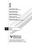
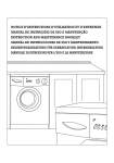
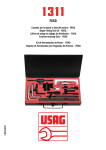
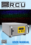
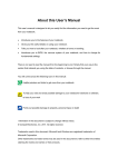
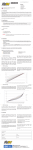
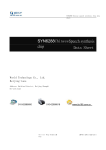
www.seuservice.com
1ST PRINTING SEPT 01
Universal Kit
Kit Installation Instructions
& Service Manual
Switchable FROM High Resolution 31K
TO Standard (Low) Resolution 15.75K.
1 - 2 PLAYER GAME
SEGA ENTERPRISES, INC. USA
MANUAL NO. 999-1318
VISIT OUR WEBSITE!
Capcom vs SNK 2
Sega Naomi System
Kit Contains List
Part #
Desc
Qty
400-5397-01
NAOMI POWER SUPPLY
1
838-13616
AUDIO POWER AMP 2 CH
1
560-5407-UL
AUDIO XFORMER 120V
1
838-13683-93CV1
JAMMA I/O BD (NAOMI)
1
600-7141-200
USB CABLE
1
600-7009-2500
VGA VIDEO CABLE
1
840-0051D-01
ASSY CASE PC1 DIMM BD
1
600-7247-500
CABLE SCSI TYPE 2 500MM
1
837-13938
I/O CTRL BD JVS ENCORD.
1
LOC. PURCHASE
SERVICE SWT BRKT ASSY
1
XKT-0833
GD-ROM DRIVE KIT
1
999-1326
JOYSTICK, COMP. BLUE
2
999-1327
BUTTON, COMP. BLUE
4
999-1328
BUTTON, COMP. RED
4
999-1325
BUTTON, COMP. GREEN
4
999-1329
SWITCH PB LARGE
2
1
www.seuservice.com
Capcom vs SNK 2
Sega Naomi System
Kit Contains List
Part #
Desc
999-1330
MARQUEE ART
1
999-1331
INSTR. SHEET (PLAYER)
1
999-1332
INSTR. SHEET #2 (CNTRL)
1
999-1333
SIDE ART
2
999-1334
CTRL PNL OVERLAY
1
999-1335
DECAL BTTN (LIGHT)PNCH-RED
2
999-1336
DECAL BTTN (MIDDLE)PNCH-GRN
2
999-1337
DECAL BTTN (HEAVY)PNCH-BL
2
999-1338
DECAL BTTN (LIGHT)KICK-RED
2
999-1339
DECAL BTTN (MIDDLE)KICK-GRN
2
999-1340
DECAL BTTN (HEAVY)KICK-BL
2
www.seuservice.com
Qty
2
DESIGNED RELATED PARTS
MARQUEE ART
999-1330
CTRL PNL OVERLAY
999-1334
INSTR. SHEET #2 (CNTRL)
999-1332
3
www.seuservice.com
SIDE ART
999-1333
999
INSTR. SHEET (PLAYER)
999-1331
DECAL BTTN (LIGHT)PNCH-RED[999-1335]
DECAL BTTN (MIDDLE)PNCH-GRN[999-1336]
DECAL BTTN (HEAVY)PNCH-BL[999-1337]
NOT PICTURED
DECAL BTTN (LIGHT)KICK-RED [999-1338]
DECAL BTTN (MIDDLE)KICK-GRN [999-1339]
DECAL BTTN (HEAVY)KICK-BL [999-1340]
www.seuservice.com
4
Feb 9. 2000
SERVICE BULLETIN
SEGA Service Department
45133 Industrial Drive
Fremont, Ca. 94538
120
http://www.seuservice.com
Phone: 415.701.6580
Fax: 415.701.6594
SPECIAL NOTICE FOR
ALL SEGA NAOMI KITS
PROBLEM:
The SEGA Naomi Game kits are actually ‘JAMMA Dependent’. What this means exactly is they will only
install into existing JAMMA Cabinets. If an operator tries to install these kits into a Non-JAMMA cabinet,
they will first have to bring the wiring up to JAMMA Standards.
SOLUTION:
°
°
Step 1 Disconnect the games original DC Power Supply. You may only use the power supply provided
with your kit. Be sure to set the voltages going to your Game BD to 5.1 and 3.3 volts DC to assure proper
operation ( Measure on Square Connector at Game BD. Yellow = 5vdc / Brown = 3.3vdc / White = Gnd )
Step 2 You MUST USE THE COIN METER SUPPLIED WITH YOUR KIT to assure proper Coin
acceptance. A minimum 18 Gauge wire should be used from the Coin Meter 1 output line on your
JAMMA Harness. The 5vdc ( Yellow ) wire found in the wiring bag of your kit MUST BE USED for the
supply voltage to the meter.
Not following the directions provided herein may cause your game to malfunction.
All electrical work should be performed by the site’s Serviceman or Technician.
In order to prevent an electric shock and short circuit, be sure to turn power off before performing
work or touching the interior parts of the product.
Be careful so as not to damage wirings. Damaged wiring can cause an electric shock or short circuit
accident.
Do not touch places other than those specified. Touching places not specified can cause an electric
shock or short circuit accident.
If you have any questions please contact the SEGA Service Department at the numbers given above.
5
www.seuservice.com
INSTALLATION INSTRUCTIONS
1) First. Remove all access panels from the game. Locate the original game Logic PCB’s & Power
Supply and remove from the Cabinet by first disconnecting all harnesses from the boards. (You need
only to splice in the Main Power (110v AC) into the 3-Pin Connector (GRN/WHT/BLK).)
2) Remove all existing game harnesses (we suggest using New Jamma Harnesses (NOT contained in the
kit) to ensure reliability).
3) Locate the most convenient and open area of the cabinet to mount the Capcom vs. SNK2 Naomi
System Assembly. Make sure this area is free and clear of all cable harnesses and grounds, cable
clamps, etc.
Vacuum out or clean bottom of cabinet of dirt & miscellaneous parts (e.g.
screws, loose coins / tokens, etc.).
Remove all exterior decals and repair any cabinet damage. Repaint
cabinet if necessary. Remove the Monitor Plexi or if your game plexi has
Silk-screened artwork, you will need to strip it off.
4) Connect the JAMMA Harnesses to the JVS-JAMMA Interface Boards. Separate the wires from each
other (i.e. Control Panel, Video, Speaker, Power Supply). Run the various harnesses to the part of the
cabinet they go to ensuring they are dressed properly & secured to the cabinet. Locate the Volume/
Speaker/Coin Meter Cable and connect to your existing Switch Bracket or use the new one included
with the kit. Note: If you are using a VGA Compatible Monitor you can run your VGA Cable directly
to the monitor or connect it to your JVS JAMMA Interface for RGB Conversion to your JAMMA
Cables.
5) Remove Marquee from cabinet and cut to fit the new Capcom vs. SNK 2 Marquee in place.
REPLACE old Joysticks & Buttons with the NEW ones supplied in Kit.
6) First remove all Joystick and Button assemblies from the Control Panel. Remove Lexan and Control
Panel Overlay. Proceed to clean surface of the Control Panel by removing all adhesive and dirt. Fill
in or plug up existing button holes to set up a blank work area for your new controls.
7) Install the new Control Panel Overlay by carefully peeling off the paper backing and laying down on
the panel. Smooth it out, starting in the center and working your way to the edges (removing all of
the trapped air pockets). If necessary, cut the edges of the overlay excess and fold under panel.
8) Cut out the button and Joystick Holes. Install Joystick and buttons from kit into the Control Panel
and tighten down. Connect all game harness wires to switches and buttons.
www.seuservice.com
6
INSTALLATION INSTRUCTIONS
9) Proceed to place new decals on the sides of the cabinet. Locate a new monitor bezel, if needed, and
replace glass, if required (due scratches). Install Instruction Placard to the back of the Monitor Glass.
NOTE: As a precaution, disconnect the JAMMA Harness from the I/O Boards and turn power on. With a
Multi-Meter, measure the 5v and 3.3v. Adjust if necessary to 5.15v DCand 3.3vDC. Measure the +12 to
ensure the wires and voltages are in the correct position. Turn power off. Plug in the JAMMA Harness once
again to the I/O Boards. The Attract Mode should appear on the screen.
Adjust the SIZE, CONTRAST, BRIGHTNESS, and COLORS on the
Monitor for optimum appearance. Adjust VERTICAL/HORIZONTAL
Hold to get a stable picture, if required.
Enter DIAGNOSTICS and adjust the Volume Level, test all Buttons &
Joystick for proper operation & wiring. Adjust Pricing. Coin-Up and
test out a game to ensure proper play functions are as they should be.
7
www.seuservice.com
Sega Naomi System Switch
Bracket and Speaker
Installation Diagrams
(Figure 3)
To CN1 of
Amplifier Board
JAMMA Pin 8
Pin 1
Yellow Wire from Extra
Harness (+5v)
Pin 4
Pin 5
WHT/RED
GRN/RED
YEL/RED
_
+
Coin Meter
Test
Service
JAMMA Pin
JAMMA Pin
JAMMA Pin
Volume
GRY/RED
From CN2 of
Amplifier Board
From CN4 of
Amplifier Board
www.seuservice.com
ORG/RED
GRY/BLUE
ORG/BLUE
8
R
1
15
Left
Speaker
Right
Speaker
Sega Naomi System
JAMMA Harness Wiring
(JAMMA I/O BD)
(Figure 4)
Ground
1
A
Ground
Ground
2
B
Ground
+5v (Not Used)
3
C
+5v (Not Used)
+5v (Not Used)
4
D
+5v (Not Used)
(Not Used)
5
E
(Not Used)
+12v (Not Used)
6
F
+12v (Not Used)
Key
7
H
Key
Coin Meter 1
8
J
Coin Meter 2
(Not Used)
9
K
(Not Used)
(Not Used)
10
L
(Not Used)
(Not Used)
11
M
(Not Used)
Video Red
12
N
Video Green
Video Blue
13
P
Video Sync
Video Ground
14
R
Service
Test
15
S
(Not Used)
Coin 1
16
T
Coin 2
1P Start
17
U
2P Start
1P UP
18
V
2P UP
1P Down
19
W
2P Down
1P Left
20
X
2P Left
21
Y
2P Right
Attack 1P (1P SW1)
22
Z
Attack 2P (2P SW1)
Grapple 1P (1P SW2)
23
a
Grapple 2P (2P SW2)
Support 1P (1P SW3)
24
b
Support 2P (2P SW3)
(Not Used)
25
c
(Not Used)
(Not Used)
26
d
(Not Used)
Ground
27
e
Ground
Ground
4
28
f
Ground
1P Right
9
www.seuservice.com
Sega Naomi System
Filter Board Information
Connector Description etc.
PSW2 PSW1
Service
Switch
DIPSW1
CN4
CN3
CN2
CN1
Test
Switch
Preamp Level
Audio Out
1
2
3
VGA Level
Video Out
4
Setting for High
Resolution 31KHZ
1 -4 off
1
2
3
Setting for Standard
Resolution 15KHZ
1 on 2-4 off.
www.seuservice.com
10
Power Connectors
SOFT KIT
2
PART NO.
3
610-0624-0003
GD SOFT KIT CAPCOM VS.SNK 2
1
GDS-0003
NAOMI GDROM CAPCOM VS.SNK 2
2
3
1
DESCRIPTION
1 + 2 + 3
KEY CHIP
253-5507
DISK CASE WITH IC HOLDER
Handling the GD-ROM Disk
Do not contaminate the disks with your fingerprints or dust particles.
Contaminated disks may lower audio and video quality.
When cleaning the disks, do not use volatile chemicals (benzine, thinner, etc.),
cleaning sprays, and antistatic agents.
Do not use cracked, warped, or damaged disks.
Do not attach papers or seals onto the disks; do notscratch the disks.
Do not use the disks with a sign of peeled seals, tapes, etc.
Observing these instructions, do not insert such a non-usable disk into the GD-ROM drive. Otherwise the N
inserted disk can not be ejected.
When cleaning a heavily contaminated disk, use clean cloth that has been soaked in water and
squeezed. Then remove moisture with drycloth.
When holding a disk, be careful not to contaminate it with your fingerprints.
How to Hold a Disk
•With one hand:
Insert your forefinger into
a central hole and at the same
time put your thumb and middle
finger on the disk's 2 edges.
•With both hands:
Put your thumbs and
forefingers of both hands
on the disk's edge.
11
www.seuservice.com
© CAPCOM CO., LTD. 2001 ALL RIGHTS RESERVED. © SNK 2001
MANUAL
WARNING
U.S.A. version of this game is for the North American
countries only.
Europe version of this game is for the European countries
only.
Sales, export, or operation outside these countries may b
construed as copyright and trademark infringement and is
strictly prohibited.
Violators are subject to severe penalties and will be pro
421-11465
www.seuservice.com
12
CAUTION
For your safety, please read and abide by the following
instructions when handling the P.C. board.
Make sure the power is off before installing the board or changing
N the settings of the board.
Do not damage the wiring cables.
Do not disassemble the case.
Do not touch the board, connectors or the harness with wet hands.
N
Please keep the following instructions to keep the P.C.
board in good condition.
Do not block the ventilation slots.
Do not keep the board in extremely cold/hot places.
Do not drop or bump the board.
Do not spill any liquids on the case.
Do not disassemble the case.
Always keep the connectors clean.
Do not disconnect the connectors, cables, or the harness while the NN
N power is on.
Disassembling the case or removing the sticker may cause the termination of your
repair warranty.
No desarme la caja. Si la caja est· desarmada o hay evidencia de que lo ha estado,
se deneger·n las reparaciones.
Ne pas dÈmonter la boÓte. Au cas o˘ il apparaÓt que cette boÓte a ÈtÈ dÈmontÈe,
votre demande de rÈparation sera refusÈe.
Das Geh‰use nicht ˆffnen. Falls das Geh‰use geˆffnet wurde oder falls
ersichtlich ist, dafl es geˆffnet wurde, wird die Reparatur verweigert.
Non smontare la scatola involucro. In caso sia stata smontata, o sia evidente che
ciÚ Ë avvenuto, la riparazione sar‡ rifiutata
13
www.seuservice.com
CONTROL PANEL LAYOUT
Jump
Lever
Buttons
Moves the player to the
jump/crouch, left/right
of the screen.
SHOT 1
Light Punch
Left
Right
SHOT 4
Light Kick
Crouch
SHOT 3
SHOT 2
Heavy Punch
Middle Punch
SHOT 6
SHOT 5
* Please use the
illustrated setting for
the best possible
game play.
Heavy Kick
Middle Kick
CRT MONITOR
Either 15k or 31k horizontal monitor can be used.
Locate the DIP switch 1 on the connector side of NAOMI board.
Turn it ON for 15k monitor. Turn it OFF for 31k monitor.
(Default is set to ON)
* Please refer to page 17 "CAPCOM VS. SNK 2 SETTING TIPS" for 31k monitors.
15k monitor
31k monitor
JAMMA CONNECTOR
JAMMA CONNECTOR
SOLDER SIDE
I/O BOARD CN3
1
2
3
4
5
6
7
8
9
10
11
12
13
14
+5v
+5v
N.C.
SHOT 6 (1PW SW6)
(1P SW7) NOT USED
(1P SW8) NOT USED
N.C.
SHOT 6 (2PW SW6)
(2P SW7) NOT USED
(2P SW8) NOT USED
N.C.
N.C.
GND
GND
GND
A
1
GND
GND
B
2
GND
+5V
C
3
+5V
+5V
D
4
+5V
N.C.
E
5
N.C.
+12V
+12V
9
SP(-)
L
10 SP(+)
N.C.
M 11 N.C.
P
SERVICE SW
R 14 VIDEO GND
13 VIDEO BLUE
N.C.
S
15 TEST SW
COIN SW 2
T
16 COIN SW 1
2P LEFT
U 17 START SW 1
V 18 1P UP
W 19 1P DOWN
X 20 1P LEFT
Y 21 1P RIGHT
2P SHOT 1
Z
22 1P SHOT 1
2P SHOT 2
a
23 1P SHOT 2
2P SHOT 3
b
24 1P SHOT 3
2P SHOT 4
c
25 1P SHOT 4
2P SHOT 5
d
26 1P SHOT 5
GND
e
27 GND
GND
f
28 GND
(2P Light Punch)
(2P Middle Punch)
(2P Heavy Punch)
* Must be set for proper
operation
N 12 VIDEO RED
VIDEO SYNC
2P RIGHT
*
COIN COUNTER 1
(COIN LOCK OUT 1)
8
2P DOWN
7
J
2P UP
JP1----> 6
K
VIDEO GREEN
IN
F
H
N.C.
(COIN LOCK OUT 2)
START SW 2
OUT
COMPONENT SIDE
(2P Light Kick)
(2P Middle Kick)
(1P Light Punch)
(1P Middle Punch)
(1P Heavy Punch)
(1P Light Kick)
(1P Middle Kick)
PARTS NAME
CR7E-56DA-3.96E : (HIROSE)
OR
1168-056-009: (KEL)
www.seuservice.com
14
HOW TO ENTER THE TEST MODE
Press the Test Button inside the cabinet and the "NAOMI SYSTEM MENU" will appear on the screen.
Press the Service Button to move the "g " cursor and press the Test Button to enter various test modes.
(For the details on "NAOMI SYSTEM MENU", please refer to "NAOMI SERVICE MANUAL".)
To enter the GAME TEST MODE, move the "g " cursor to GAME TEST MODE in the NAOMI SYSTEM MENU and press the
Test Button.
g
SYSTEM MENU
JAPAN VERSION
RAM TEST
JVS TEST
SOUND TEST
C. R. T. TEST
SYSTEM ASSIGNMENTS
COIN ASSIGNMENTS
BOOKKEEPING
BACKUP DATA CLEAR
CLOCK SETTING
DIMM BOARD TEST
GAME TEST MODE
[CAPCOM VS. SNK 2 EXPORT]
EXIT
g
GAME TEST MODE
INPUT TEST
GAME DATA
GAME CONFIGURATION
PASSWORD
EXIT
SELECT WITH SERVICE BUTTON
AND
PRESS TEST BUTTON
SELECT OPTION = 1P UP or DOWN
= 1P SHOT1
START
NAOMI SYSTEM MENU
GAME TEST MODE
CAUTIONS ON NAOMI SYSTEM MENU
1)
Please set the CABINET TYPE and the MONITOR TYPE of the SYSTEM ASSIGNMENTS menu to
"2 PLAYER(S)" and "HORIZONTAL" respectively.
This game will not function properly if above is not followed.
2)
The following is the default settings of COIN ASSIGNMENTS
.
COIN CHUTE TYPEN
COIN/CREDIT SETTINGN
COIN CHUTE #1N
COIN CHUTE #2N
3)
COMMON
#1
1 COIN 1 CREDIT
1 COIN 1 CREDIT
Please refer to the following for the SEQUENCE SETTING of the COIN ASSIGNMENTS
.
SEQUENCE 1: Credits required to start the game.
SEQUENCE 2: Credits required to continue the game.
* SEQUENCE 3~8 is not available in CAPCOM VS. SNK 2.
Ex) Standard setting
N One(1) credit to start and continue the game.
SEQUENCE 1 1 CREDIT(S)
SEQUENCE 2 1 CREDIT(S)
Credits required to start the game.
Credits required to continue the game.
Ex) 2 credits start, 1 credit continue setting
N Players need 2 credits to start the game but only one credit to continue the game.
SEQUENCE 1 2 CREDIT(S)
SEQUENCE 2 1 CREDIT(S)
4)
Credits required to start the game.
Credits required to continue the game.
BOOKKEEPING 2/2 indicates the following
:
P1(P2) SEQ 1: The number of times the game was started from Player 1 and Player 2 each.
P1(P2) SEQ 2: The number of times the game was continued from Player 1 and Player 2 each.
* SEQ 3~8 is not available in CAPCOM VS. SNK 2.
Ex)
The number of "Start" of 1P side
P1 SEQ 1N
P1 SEQ 2N
The number of "Start" of 2P side
82N
36N
P2 SEQ 1N
P2 SEQ 2N
The number of "Continue" of 1P side
45
15
The number of "Continue" of 2P side
15
www.seuservice.com
GAME TEST MODE
On this screen, you can test "input signal" of the lever/buttons and can also set the game's difficulty.
Your setting will be saved in the backup RAM.
CONTROLS IN GAME TEST MODE
* Use the lever and the buttons
as illustrated.
Decide an item
Select an item
SHOT 3
SHOT 2
SHOT 1
*
Change setting
Not used
*
Not used
SHOT 6
Change setting
SHOT 5
SHOT 4
*
Select an item
*
Not used
*
Not used
Not used
GAME TEST MODE
g
INPUT TEST
GAME DATA
GAME CONFIGURATION
PASSWORD
EXIT
SELECT OPTION = 1P UP or DOWN
= 1P SHOT1
START
GAME TEST MODE
GAME TEST MODE
• INPUT TEST
Tests the "input signal" of the lever and the buttons. When the "input signal" is detected, the number changes from
"0" to "1".
* Inside INPUT TEST, you can test up to two Service Buttons. In case your cabinet has only one Service
Button, please make sure if the 1P Service Button functions properly.
(Please note however, on certain cabinets, it is possible the number changes to "1" on both 1P and 2P side.)
• GAME DATA
Shows the earning-related data. Please use the info to determine the best coin settings for your arcade.
• GAME CONFIGURATION
Sets the game play settings such as difficulty, number of rounds, timer, etc.
• PASSWORD
Enter the password to unlock the hidden features in the game.
• EXIT
Returns to NAOMI SYSTEM MENU
www.seuservice.com
16
g
GAME TEST MODE
g
INPUT TEST
GAME DATA
GAME CONFIGURATION
PASSWORD
GAME CONFIGURATION
SOUND MODEN
STEREO
DEMO SOUND HALFN OFF
CONTINUEN
ON
DIFFICULTYN
DAMAGE LEVELN
TIMER SPEEDN
GAME SPEEDN
EVENTN
JOIN-INN
DEFAULT
SAVE & EXIT
EXIT
SELECT OPTION = 1P UP or DOWN
= 1P SHOT1
START
GAME TEST MODE
EASY[*2****]HARD
LOW [*2****]HIGH
SLOW[ *2****]HIGH
SLOW[**3****]HIGH
OFF
ON
SELECT OPTION = 1P UP or DOWN
MODIFY SETTING = 1P LEFT or RIGHT
= 1P SHOT1 or SHOT2
DECIDE WITH
SHOT 1
GAME CONFIGURATION
GAME CONFIGURATION
• SOUND MODE
Please set this item to "STEREO" for normal operations. Setting to "MONAURAL" will make your sound output monaural.
• DEMO SOUND HALF
ON:N Plays the attract mode demo sound at half volume.
OFF:N Plays the attract mode demo sound at regular volume.
• CONTINUE
Set this "ON" to enable the "CONTINUE" feature.
Set this "OFF" to disable the "CONTINUE" feature.
• DIFFICULTY
Sets the game's difficulty level. There are 8 levels in total.
As the number increases, the game gets more difficult.
• DAMAGE LEVEL
Sets the attacking power. There are 4 levels in total.
As the number increases, the attacking power increases. (Thus the average play time gets shorter.)
• TIMER SPEED
Sets the timer speed. There are 4 levels in total.
As the number increases, the time elapses quicker.
• GAME SPEED
Sets the game speed. 5 levels are available.
As the number gets higher, the game speed increases.
• EVENT
Use this function for events/tournaments. If set to "ON", only 1 credit is required for 2 players "VS." game.
However, the game will be over for both players regardless of the game result.
Please set this to "OFF" for standard operations.
• JOIN-IN
Used to turn on and off the JOIN-IN feature. Please set to ON for standard operations.
If you wish the game setting to be played by 1 player only(advisable for beginners), set to OFF.
• DEFAULT
Resets all the settings to the factory defaults. (Initialise)
Not only the GAME CONFIGURATION but also the settings in NAOMI SYSTEM MENU(COIN ASSIGNMENTS, etc.) will be
reset to the following factory defaults.
ADVERTISE SOUNDN
MONITOR TYPEN
COIN CHUTE TYPEN
COIN/CREDIT SETTINGN
N
SEQUENCE SETTINGN
N
:
:
:
:
ON
HORIZONTAL
COMMON
#1 (1 coin 1 credit: Asia version)
#12 (2 coins 1 credit: European version)
: SEQ1=1 (1 credit to start)
SEQ2=1 (1 credit to continue)
For more details regarding the NAOMI SYSTEM MENU, please refer to the "NAOMI SERVICE MANUAL."
• SAVE & EXIT
Saves your GAME CONFIGURATION and COIN/SYSTEM ASSIGNMENTS and returns to the GAME TEST MODE.
(It takes approximately 2 seconds to save the settings. Please do not turn off the power while saving.)
17
www.seuservice.com
GAME CONFIGURATION OPTIONS
STEREO
MONAURAL
DEMO SOUND HALF
ON
OFF
CONTINUE
ON
OFF
SOUND MODE
DIFFICULTY
1 EASY
2
3
4
5
6
7
8 HARD
DAMAGE LEVEL
1 LOW
2
3
4 HIGH
TIMER SPEED
1 SLOW
2
3
4 HIGH
GAME SPEED
2
1 SLOW
3
4
EVENT
ON
OFF
JOIN-IN
ON
OFF
5 HIGH
*
Factory settings
* DEMO SOUND HALF setting is available only when ADVERTISE SOUND is set to ON.
ADVERTISE SOUND setting can be found under the SYSTEM ASSIGNMENTS menu of the NAOMI SYSTEM MENU.
CAPCOM VS. SNK 2 SETTING TIPS
LARGE CABINETN
Because of its simple controls, CAPCOM VS. SNK 2 can be played by any game player.
Its unique characters and beautiful graphics that can only be achieved on the NAOMI board will surely appeal even to the
people who had never played video games before.
Turn this
For this universal appeal of the game, we strongly recommend you to install this
switch off.
game in a large cabinet and place it at the front of your arcade.
For
15K MONITOR
31K MONITOR CABINET
The NAOMI board is capable of handling the screen resolution that is three times as
high as the CP-SYSTEM board.
To exercise its maximum performance, it is indispensable to install the board in the
cabinet equipped with 31K monitor that is capable of high resolution graphics. (Ex.
"BLAST CITY" "MEGALO 410" etc. from Sega)
To enjoy NAOMI's graphics at its best, please use the cabinet with 31K monitor.
(When using 31K monitor, please set the DIP switch on the NAOMI board's
connector side as described in the right chart.)
www.seuservice.com
18
(Default Setting)
For
31K MONITOR
According to your DIMM BD type, attach the correct sticker as follows.
1
2
442-00084B-01 (STICKER 840-0084B-01)
Attached place
1
PART NO.
DESCRIPTION
840-0001F
ASSY CASE NAO DIMM BD COM
2
KEY CHIP
1 + 2
840-0084B-01
DIMM BD NAO CPvsSNK2
2
1
442-00084B-02 (STICKER 840-0084B-02)
Attached place
1
PART NO.
DESCRIPTION
840-0004F
ASSY CASE NAO DIMM BD COM RTOS
2
1 + 2
KEY CHIP
840-0084B-02
RT DIMM BD NAO CPvsSNK2
19
www.seuservice.com
SOFT KIT
STOP
IMPORTANT
Handling the GD-ROM Disc
Do not contaminate the discs with your
fingerprints or dust particles. Contaminated
discs may lower audio and video quality.
When cleaning the discs, do not use volatile
chemicals (benzine, thinner, etc.), cleaning
sprays, and antistatic agents.
Do not use cracked, warped, or damaged discs.
Use clean cloth to wipe
Do not attach papers or seals onto the discs; do
the disc gently and into a
radial direction.
not scratch the discs.
Do not use the discs with a sign of peeled seals,
tapes, etc.
Observing these instructions, do not insert such a non-usable disc into
the GD-ROM drive. Otherwise the inserted disc can not be ejected.
When cleaning a heavily contaminated disc, use clean cloth that has
been soaked in water and squeezed. Then remove moisture with dry
cloth.
When holding a disc, be careful not to contaminate it with your
fingerprints.
How to Hold a Disc
With both hands:
Put your thumbs and forefingers of both
hands on the disc's 4 circumference tips.
With one hand:
Insert your forefinger into a central
hole and at the same time put your
thumb and middle finger on the
disc's 2 circumference tips.
How to Handle the Key Chip
The key chip is a precision device. Handle it carefully because it may be
damaged by heat, shock, and static electricity.
Use the key chip with the GD-ROM disc of the corresponding game that
has been shipped together with the key chip.
www.seuservice.com
20
4
2
3
2
1
When you order the GD-ROM disc only, please mention the Part No. 610-0625-****.
1 + 2 + 3 + 4
PART NO.
DESCRIPTION
610-0630-0008
GD SOFT KIT CPvsSNK2 ENG
1
NAOMI GDROM CPvsSNK2
2
KEY CHIP
3
420-6620-01
SERVICE MANUAL CPvsSNK2 ENG
4
253-5507
DISC CASE WITH IC HOLDER
1 + 4
610-0625-0015
GD SOFT CPvsSNK2
21
www.seuservice.com
GAME BOARD
Do not expose the Game Board so as to avoid causing an accident or
malfunctioning.
Static electricity discharge can damage electronic parts on the IC Board.
Before starting work by opening the Shield Case Lid, be sure to touch
grounded metallic surfaces to discharge physically charged static electricity.
When replacing the Game Board, refer to the CVT Manual and Instruction
Manual.
PART NO.
DESCRIPTION
ASSY CASE ( 1 + 2 )
840-0084D-01
840-0084D-02
840-0084D-03
840-0084D-04
ASSY CASE NAO CPvsSNK2 USA
ASSY CASE NAO CPvsSNK2 EXP
ASSY CASE NAO CPvsSNK2 KOR
ASSY CASE NAO CPvsSNK2 AUS
:USA
:OTHERS
:KOREA
:AUSTRALIA
1 ASSY CASE NAOMI
MAIN BOARD
840-0001A-01
840-0001A-02
840-0001A-03
840-0001A-04
ASSY CASE NAOMI MAIN BD USA
ASSY CASE NAOMI MAIN BD EXP
ASSY CASE NAOMI MAIN BD KOR
ASSY CASE NAOMI MAIN BD AUS
:USA
:OTHERS
:KOREA
:AUSTRALIA
2 ROM CASE
840-0084C
ROM CASE NAO CPvsSNK2
www.seuservice.com
22
TRANSFORMER
50
838-13616
17V
0V
0V
17V
120V
AUDIO POWER AMP 2CH
560-5407
JST VH 4P
P C
1 2 3 4 5 6
31
50
50
41
51
50
5k pot
71
50
10
30
50
50
10
30
[Extra] [GD ROM DRIVE]
72
92
120 Vac Input
0V
80
91
1
2
3
WHITE(U/P)
P C
3
1
Phono
plugs
2
SPEAKER OUTPUTS
1
6
838-13683-91
23
To PIN 8
of Jamma
CN6
50 50 10 10 30 30
JST VL
GND
GND
P C
+3.3V
+5V
GND
GND
GND
+3.3V
+5V
+12V
P C
MUST BE SET TO "IN"
TO USE INPUTS ON CN3
OUT
IN
To Extra
Yellow Wire
JP1
SW REGU FOR JVS
COIN COUNTER
VCC
VCC
NC
1P SW6
1P SW7
1P SW8
NC
2P SW6
2P SW7
2P SW8
NC
NC
GND
GND
400-5397
1
2
3
4
5
6
7
8
9
10
11
12
13
14
JST VL
CN3
600-7141-050
www.seuservice.com
10
20
30
40
50
60
70
80
A
B
C
D
E
JAMMA CONNECTIONS USED ARE:
° VIDEO OUT
° SWITCH INPUTS
° SWITCH GROUND RETURNS
° COIN COUNTER OUTPUT
600-7155
600-6743-050
NOTE: THERE ARE TO BE NO
CONNECTIONS MADE TO THE
JAMMA INTERFACE OTHER THAN
THE ABOVE FOREMENTIONED.
NAOMI KIT UNIVERSAL
WIRING DIAGRAM (1/1)
Warranty
Your new Sega Product is covered for a period of 90 days from the date of shipment. This certifies
that the Printed Circuit Boards, Power Supplies and Monitor are to be free of defects in workmanship or materials under normal operating conditions. This also certifies that all Interactive Control
Assemblies are to be free from defects in workmanship and materials under normal operating conditions. No other product in this machine is hereby covered.
Sellers sole liability in the event a warranted part described above fails shall be, at its option, to
replace or repair the defective part during the warranty period. For Warranty claims, contact your
Sega Distributor.
Should the Seller determine, by inspection that the product was caused by Accident, Misuse, Neglect, Alteration, Improper Repair, Installation or Testing, the warranty offered will be null and void.
Under no circumstances is the Seller responsible for any loss of profits, loss of use, or other damages.
This shall be the exclusive written Warranty of the original purchaser expressed in lieu of all other
warranties expressed or implied. Under no circumstance shall it extend beyond the period of time
listed above.