1
TECHNICAL MANU
AL
MANUAL
GME8
33-3/8" 80% Gas Furnace
Upflow/Horizontal
• Refer to current Service Manual RS6610004 for installation, operation, and troubleshooting information.
• All safety information must be followed as provided in the Service Manual.
• Refer to the appropriate Parts Catalog for part number information.
• Model numbers listed on page 3.
®
C
This manual is to be used by qualified, professionally trained HVAC technicians only.
Goodman does not assume any responsibility for property damage or personal injury due
to improper service procedures or services performed by an unqualified person.
Copyright ©2011, 2013 Goodman Manufacturing Company, L.P.
US
RT6621021r2
March 2013
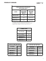
PRODUCT IDENTIFICATION
The model and manufacturing number are used for positive identification of component parts used in manufacturing.
Please use these numbers when requesting service or parts information.
G
M
E
8
BRAND:
G: Goodman®
Brand
SUPPLY
TYPE:
M: Upflow/Horizontal
A* Revisions
NOMINAL INPUT:
060: 70,000 Btu
080: 90,000 Btuh
100: 115,000 Btuh
2
B
AFUE:
8: 80%
AIRFLOW
CAPABILITY:
3: 1200
4: 1600
5: 2000
B* Revisions
NOMINAL INPUT:
060: 60,000 Btu
080: 80,000 Btuh
100: 100,000 Btuh
X
A
A
ADDITIONAL
FEATURES:
N: Natural Gas
X: LowNOx
MINOR
REVISION:
CABINET WIDTH:
B: 17 1/2"
C: 21"
D: 24.5"
HIGH VOLTAGE!
Disconnect ALL power before servicing or installing this unit. Multiple power
sources may be present. Failure to do so may cause property damage, personal
injury or death.
Goodman will not be responsible
for any injury or property damage
arising from improper service or service procedures. If
you install or perform service on this unit, you assume
responsibility for any personal injury or property damage
which may result. Many jurisdictions require a license to
install or service heating and air conditioning equipment.
WARNING
3
MAJOR
REVISION:
FURNACE
TYPE
E: Eco-Tech
Motor
WARNING
060
Installation and repair of this unit
should be performed ONLY by individuals meeting the requirements of an "entry level technician", at a minimum, as
specified by the Air-Conditioning, Heating, and Refrigeration Institute (AHRI). Attempting to install or repair this
unit without such background may result in product
damage, personal injury or death.
WARNING
PRODUCT IDENTIFICATION
The model and manufacturing number are used for positive identification of component parts used in manufacturing.
Please use these numbers when requesting service or parts information.
GME80603B*A*
GME80603B*B*
GME80805C*A*
GME80805C*B*
GME81005C*A*
GME81005C*B*
GME80805D*A*
*All models are Natural Gas and low NOx models.
WARNING
The United States Environmental Protection Agency (“EPA”) has issued various regulations regarding the introduction and disposal of refrigerants introduced into this unit. Failure to follow
these regulations may harm the environment and can lead to the imposition of substantial fines.
These regulations may vary by jurisdiction. Should questions arise, contact your local EPA office.
Do not connect or use any device
that is not design certified by Goodman for use with this unit. Serious
property damage, personal injury, reduced unit performance and/or hazardous conditions may result from the
use of such non-approved devices.
WARNING
To prevent the risk of property
damage, personal injury, or death,
do not store combustible materials or use gasoline or
other flammable liquids or vapors in the vicinity of this
appliance.
WARNING
3
PRODUCT DESIGN
General Operation
GME8 furnaces are equipped with an electronic ignition device used to light the burners and an induced draft blower to
exhaust combustion products.
An interlock switch prevents furnace operation if the blower
door is not in place. Keep the blower access door in place
except for inspection and maintenance.
This furnace is also equipped with a self-diagnosing electronic control module. In the event a furnace component is
not operating properly, the control module LED will flash on
and off in a factory-programmed sequence, depending on
the problem encountered. This light can be viewed through
the observation window in the blower access door. Refer to
the Troubleshooting Chart for further explanation of the LED
codes and Abnormal Operation - Integrated Ignition Control
section in the Service Instructions for an explanation of the
possible problem.
The rated heating capacity of the furnace should be greater
than or equal to the total heat loss of the area to be heated.
The total heat loss should be calculated by an approved
method or in accordance with “ASHRAE Guide” or “Manual
J-Load Calculations” published by the Air Conditioning Contractors of America.
*Obtain from: American National Standards Institute 1430
Broadway New York, NY 10018
Location Considerations
NOTE: The vertical height of the Category I venting system
must be at least as great as the horizontal length of the
venting system.
2. Line voltage wiring can enter through the right or left side
of the furnace. Low voltage wiring can enter through the
right or left side of furnace.
3. Conversion kits for high altitude natural or propane gas
operation are available. See High Altitude Derate chart
for details.
4. Installer must supply the following gas line fittings, depending on which entrance is used:
Left -- Two 90º Elbows, one close nipple, straight pipe.
•
The furnace should be as centralized as is practical
with respect to the air distribution system.
•
Do not install the furnace directly on carpeting, tile, or
combustible material other than wood flooring.
•
When suspending the furnace from rafters or joists,
use 3/8" threaded rod and 2” x 2” x 3/8” angle as
shown in the Installation and Service Instructions. The
length of the rod will depend on the application and
clearance necessary.
•
When installed in a residential garage, the furnace
must be positioned so the burners and ignition source
are located not less than 18 inches (457 mm) above
the floor and protected from physical damage by vehicles.
WARNING
TO PREVENT POSSIBLE PERSONAL INJURY OR DEATH DUE TO ASPHYXIATION,
THIS FURNACE MUST BE CATEGORY I VENTED. DO NOT VENT USING
CATEGORY III VENTING.
Notes:
1. Category I Venting is venting at a non-positive pressure.
A furnace vented as Category I is considered a fan-assisted appliance and the vent system does not have to
be “gas tight.”
4
NOTE: Gas furnaces with induced draft blowers draw
products of combustion through a heat exchanger allowing,
in some instances, common venting with natural draft
appliances (i.e. water heaters). All installations must be
vented in accordance with National Fuel Gas Code NFPA
54/ANSI Z223.1 - latest edition. In Canada, the furnaces
must be vented in accordance with the National Standard of
Canada, CAN/CSA B149.1 and CAN/CSA B149.2 - latest
editions and amendments.
Right -- Straight pipe to reach gas valve.
PRODUCT DESIGN
Accessibility Clearances (Minimum)
High Altitude Derate
Unobstructed front clearanace of 24" for servicing is recommended.
IMPORTANT NOTE: The furnace as shipped requires no
change to run between 0 - 4500 feet. Do not attempt to
increase the firing rate by changing orifices or increasing
the manifold pressure below 4500 feet. This can cause poor
combustion and equipment failure.
Top clearance for horizontal confirguration - 1"
MINIMUM CLEARANCE TO COMBUSTIBLE MATERIALS - INCHES
Vent
Top
Sides
Rear
Front Bottom
SW
B
1
0
3
C
6
1
1
Approved for line contact in the horizontal postion.
* 24" clearance for serviceability recommended.
** Single Wall Vent (SW) to be used only as a connector.
Refer to venting tables outlined in the installation manual for
additional venting requirements.
24" at front is required for servicing or cleaning.
Note: In all cases accessibility clearance shall take precedence over clearances from the enclosure where accessibility clearances are greater. All dimensions are given in inches.
High altitude installations above 4500 feet may require both
a pressure switch and an orifice change. These changes
are necessary to compensate for the natural reduction in
the density of both the gas fuel and the combustion air at
higher altitude.
For installations above 4500 feet, please refer to your distributor for required kit(s). Contact the distributor for a tabular
listing of appropriate manufacturer’s kits for propane gas
and/or high altitude installations. The indicated kits must be
used to insure safe and proper furnace operation. All conversions must be performed by a qualified installer, or service agency.
5
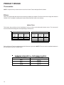
PRODUCT DIMENSIONS
GME8******A
UNITS
A
B
C
D
GME80603B***
17.5
16
33-3/8
28
GME80805C***
GME81005C***
21
19.5
33-3/8
28
GME80805D***
24.5"
23"
33-3/8
28
All dimensions are in inches.
6
PRODUCT DESIGN
GME8***A*
PRESSURE SWITCH TRIP POINTS
AN D USAGE CH ART
MODEL
TRIP POINT
ID BLOWER
PRESSURE
SWITCH
ID BLOWER
PRESSURE
SWITCH
PART #
GME80603B*A*
-0.60
B1370142
GME80805C*A*
-0.75
B1370179
GME81005C*A*
-0.90
0130F00041
*
All installations above 7,000 ft. require a pressure switch change.
*
Negative pressure readings are in inches of water column (*w.c.)
For installations in Canada, the GME8 furnace is certified only to 4,500 ft.
PRIMARY LIMIT
Part Number
20162903
Open Setting (°F)
160
GME80603B*A*
1
GME80805C*A*
1
GME81005C*A*
1
ROLLOUT LIMIT SWITCHES
AUXILIARY LIMIT SWITCHES
Part Number
10123529
Part Number
0130F00038
Open Setting (°F)
300
Open Setting (°F)
120
GME80603B***
2
GME80603B***
1
GME80805C***
2
GME80805C***
1
GME81005C***
2
GME81005C***
1
7
PRODUCT DIMENSIONS
GME8***B*
PRESSURE SWITCH TRIP POINTS
AND USAGE CHART
MODEL
TRIP POINT
ID BLOWER
PRESSURE
SWITCH
ID BLOWER
PRESSURE
SWITCH
PART #
GME80603B*B*
-0.90
013 0F00041
GME80805C*B*
-0.80
013 0F00042
GME80805D*A*
-0.80
013 0F00042
GME81005C*B*
-0.80
013 0F00042
*
All installations above 4,500 ft. require a pressure switch change.
*
Negative pressure readings are in inches of water column (*w.c.)
For installations in Canada, the GME8 furnace is certified only to 4,500 ft.
PRIMARY LIMIT
Part Number
20162904
20162903
Open Setting (°F)
150
160
GME80603B*B*
1
---
GME80805C*B*
---
1
GME81005C*B*
1
---
GME80805D*A*
---
1
ROLLOUT LIM IT SW ITCHES
8
AUXILIARY LIMIT SWITCHES
Part Number
10123529
Part Number
0130F00 038
Open Setting (°F)
300
Open Setting (°F)
120
GME80603B***
2
GME80603B***
1
GME80805C***
2
GME80805C***
1
GME81005C***
2
GME81005C***
1
GME80805D***
2
GME80805D***
1
PRODUCT DESIGN
Coil Matches:
A large array of Amana® brand coils are available for use with the new GME8 furnaces, in either upflow or horizontal
applications. These coils are available in both cased and uncased models (with the option of a field installed TXV expansion
device). These 80% furnaces match up with the existing Amana® brand coils as shown in the chart below.
Coil Matches (for Goodman units using R22 and R-410A):
C
A
P
F
1824
A
6
EXPANSION
DEVICE:
F: Flowrater
PRODUCT
TYPE:
C: Indoor Coil
CABINET FINISH:
U: Unpainted
P: Painted
N: Unpainted Case
APPLICATION
A: Upflow/Downflow Coil
H: Horizontal A Coil
S: Horizontal Slab Coil
A
REVISION
A: Revision
REFRIGERANT
CHARGE:
6: R-410A or R-22
2: R-22
4: R-410a
NOMINAL WIDTH FOR GAS FURNACE
A: Fits 14" Furnace Cabinet
B: Fits 17 1/2" Furnace Cabinet
C: Fits 21" Furnace Cabinet
D: Fits 24 1/2" Furnace Cabinet
N: Does Not Apply (Horizontal Slab Coils)
NOMINAL CAPACITY RANGE
@ 13 SEER
1824: 1 1/2 to 2 Tons
3030: 2 1/2 Tons
3636: 3 Tons
3642: 3 to 3 1/2 Tons
3743: 3 to 3 1/2 Tons
4860: 4 & 5 Tons
4961: 4 & 5 Tons
• All CAPF coils in B, C, & D widths have insulated blank off plates for use with one size smaller furnaces.
• All CAPF coils have a CAUF equivalent.
• All CHPF coils in B, C & D heights have an insulated Z bracket for use with one size smaller furnace.
• All proper coil combinations are subject to being AHRI rated with a matched outdoor unit.
9
PRODUCT DESIGN
Thermostats:
NOTE: Complete lineup of thermostats can be found in the Thermostat Specification Sheets.
Filters:
Filters are required with this furnace and must be provided by the installer. The filters used must comply with UL900 or
CAN/ULCS111 standards. Installing this furnace without filters will void the unit warranty.
Upflow Filters
This furnace has provisions for the installation of return air filters at the side and/or bottom return. The furnace will
accommodate the following filter sizes depending on cabinet size:
Cabinet
Width
(in.)
All
Side Return(s)
Approx.
Nominal
Filter Size Flow Area
(in.)
(in2)
16 x 25 x 1
400
Cabinet
Width
(in.)
Bottom Return
Approx.
Nominal
Filter Size Flow Area
(in.)
(in2)
17-1/2
14 x 25 x 1
350
21
16 x 25 x 1
400
Refer to Minimum Filter Area tables to determine filter area requirement. NOTE: Filters can also be installed elsewhere in
the duct system such as a central return.
MINIMUM FILTER SIZES for DISPOSABLE FILTERS
FURNACE INPUT
FILTER SIZE
2
60M
483 in
2
80M
640 in
2
100M
800 in
DISPOSABLE NOMINAL 300 F.M. FACE VELOCITY
10
PRODUCT DESIGN
Dual$aver Configuration & Operation
Dual$aver
This furnace is capable of the following heating modes:
• Single Stage (Factory Setting)
• Modified Two-Stage
> Fixed 5-Min. Low Stage
> Auto Time (1-12 Min.) Low Stage
To change from the factor single-stage operation, adjust the
dipswitches on the ignition control as follows:
HEAT OFF
DELAY
MODE
SECOND
DELAY
SECOND
DELAY
2-STAGE
1-STAGE
SECOND
STAGE
ONLY
AUTO
* Switches for White-Rodgers board shown above
With other venders, order of switches may vary
but functionality stays the same.
Note: This furnace is designed to be used
with a single-stage thermostat.
Start
Start
Call for Heat
Call for Heat
Safety Circuit Check
Safety Circuit Check
Start Furnace
in Low Stage
Low-Heat Blower
Start Furnace
in Low Stage
Low-Heat Blower
Delay Time (5 Min)
Delay Time (1-12 Min)
Gas Valve Switch
to 2nd Stage
Blower Switch to
Hi Heat Operation
Gas Valve Switch
to 2nd Stage
Blower Switch to
Hi Heat Operation
T-Stat Satisfied
T-Stat Satisfied
11
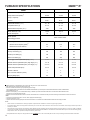
FURNACE SPECIFICATIONS
GME8***A*
GME80603B*A*
GME80805C*A*
GME81005C*A*
70,000
90,000
115,000
56,000
72,000
92,000
Output, LP (BTUH)
48,000
64,000
80,000
A.F.U.E.
80.0%
80.0%
80.0%
Rated External Static (" w.c.)
.20 - .50
.20 - .50
.20 - .50
Temperature Rise (°F)
20 - 50
35 - 65
35 - 65
Pressure Switch Trip Point ("w.c.")
-0.60
-0.75
-0.90
Blower Wheel (D" x W")
10 X 8
10 X 10
10 X 10
1/2
1
1
MODEL
( 1)
Input, Natural Gas (BTUH)
Output, Natural Gas (BTUH)
(1)
Blower Horsepower
Blower Speeds
Refer to airflow charts
Max CFM @ 0.5 E.S.P.
Power Supply
120.0
120.0
120.0
8.2
14.8
14.8
15
15
15
40
40
40
Primary Limit Setting (°F)
160
160
160
Auxiliary Limit Setting (°F)
120
120
120
Rollout Limit Setting (°F)
300
300
300
7 / 11
7 / 11
7 / 11
Manifold Pressure (Natural/Propane) High Stage (" w.c.)
3.5 / 10
3.5 / 10
3.5 / 10
Manifold Pressure (Natural/Propane) Low Stage ("w.c.)
2.0 / 6.0
2.0 / 6.0
2.0 / 6.0
Orifice Size (Natural/Propane)
43 / 55
43 / 55
43 / 55
Number of Burners
3
4
5
Vent Connector Diameter (inches)
4
4
4
Shipping Weight (lbs.)
98
116
120
Minimum Circuit Ampacity (MCA)
(2)
( 3)
Maximum Overcurrent Device
Transformer (VA)
Gas Supply Pressure (Natural/Propane) (" w.c.)
1 Natural Gas BTU/h. For altitudes above 2,000’, reduce input rating 4% for each 1,000’ above sea level.
2 DOE AFUE based upon Isolated Combustion System (ICS)
3 Vent and combustion air diameters may vary depending upon vent length.
Refer to the latest editions of the National Fuel Gas Code NFPA 54/ANSI Z223.1 (in the USA) and the Canada National Standard of Canada, CAN/CSA B149.1
and CAN/CSA B142.2 (in Ca
4 Minimum Circuit Ampacity = (1.25 x Circulator Blower Amps) + ID Blower amps. Wire size should be determined in accordance with National Electrical Codes.
Extensive wire runs will require larger wire sizes.
5 Maximum Overcurrent Protection Device refers to maximum recommended fuse or circuit breaker size. May use fuses or HACR-type circuit breakers of the same size as noted.
Notes:
• All furnaces are manufactured for use on 115 VAC, 60 Hz, single-phase electrical supply.
• Gas Service Connection ½” FPT
• Important: Size fuses and wires properly and make electrical connections in accordance with the National Electrical Code and/or all existing local codes.
NOTES:
*
These furnaces are manufactured for natural gas operation. Optional Kits are available for conversion to propane gas operation.
*
For elevations above 2000 ft. the rating should be reduced by 4% for each 1000 ft. above sea level. The furnace must not be derated, orifice changes should only be made if
necessary for altitude.
*
The total heat loss from the structure as expressed in TOTAL BTU/HR must be calculated by the manufactures method in accordance with the "A.S.H.R.A.E. GUIDE" or "MANUAL
J-LOAD CALCULATIONS" published by the AIR CONDITIONING CONTRACTORS OF AMERICA. The total heat loss calculated should be equal to or less than the heating capacity.
Output based on D.O.E. test procedures, steady state efficiency times output.
Unit specifications are subject to change without notice. ALWAYS refer to the unit's serial plate for the most up-to-date general and electrical information.
12
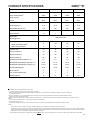
FURNACE SPECIFICATIONS
GME8***B*
GME80603B*B*
GME80805C*B*
GME80805D*A*
GME81005C*B*
60,000
80,000
80,000
100,000
Output, Natural Gas (BTUH)
48,000
64,000
64,000
80,000
Output, LP (BTUH)
48,000
64,000
64,000
80,000
A.F.U.E.
80.0%
80.0%
80.0%
80.0%
Rated External Static (" w.c.)
.20 - .50
.20 - .50
.20 - .50
.20 - .50
Temperature Rise (°F)
20 - 50
35 - 65
30 - 60
35 - 65
Pressure Switch Trip Point ("w.c.")
-0.90
-0.80
-0.80
-0.80
Blower Wheel (D" x W")
10 X 8
10 X 10
10 X 10
10 X 10
1/2
1
MODEL
Input, Natural Gas (BTUH)(1)
(1)
Blower Horsepower
1
1
Blower Speeds
Refer to airflow charts
Max CFM @ 0.5 E.S.P.
Power Supply
120.0
120.0
120.0
120.0
8.2
14.8
14.8
14.8
15
15
15
15
40
40
40
40
Primary Limit Setting (°F)
150
160
160
150
Auxiliary Limit Setting (°F)
120
120
120
120
Rollout Limit Setting (°F)
300
300
300
300
7 / 11
7 / 11
7 / 11
7 / 11
Manifold Pressure (Natural/Propane) High Stage (" w.c.)
3.5 / 10
3.5 / 10
3.5 / 10
3.5 / 10
Manifold Pressure (Natural/Propane) Low Stage ("w.c.)
2.0 / 6.0
2.0 / 6.0
2.0 / 6.0
2.0 / 6.0
Orifice Size (Natural/Propane)
45 / 55
45 / 55
45 / 55
45 / 55
Number of Burners
3
4
4
5
Vent Connector Diameter (inches)
4
4
4
4
Shipping Weight (lbs.)
98
116
123
120
(2)
Minimum Circuit Ampacity (MCA)
(3)
Maximum Overcurrent Device
Transformer (VA)
Gas Supply Pressure (Natural/Propane) (" w.c.)
1 DOE AFUE based upon Isolated Combustion System (I CS)
2 Vent and combustion air diameters may vary depending upon vent length.
Ref er to the latest editions of the National Fuel Gas Code NFPA 54/ ANSI Z223.1 (in the USA) and the Canada National Standard of Canada, CAN/CSA B149. 1
and CAN/CSA B142.2 (in Ca
3 Minimum Circuit Ampacity = (1.25 x Circulator Blower Amps) + I D Blower amps. Wire size should be det ermined in accordance with National Elect rical Codes.
Ext ens ive wire runs will require larger wire sizes.
4 Maximum Overcurrent Protection Device refers to maximum recommended fuse or circ uit breaker size. May use fuses or HACR-type circuit breakers of the same s ize as noted.
Notes:
• All furnaces are manufactured f or use on 115 VAC, 60 Hz, single-phase elect rical supply.
• G as Service Connect ion ½” FPT
• Important : Size fuses and wires properly and make electrical connections in ac cordance wit h t he National Elect rical Code and/ or all exis ting local codes.
NOTES:
*
These furnaces are manufactured for natural gas operation. Optional Kits are available for conversion to propane gas operation.
*
The total heat loss from the structure as expressed in TOTAL BTU/HR must be calculated by the manufactures method in accordance with the "A.S.H.R.A.E. GUIDE" or "MANUAL
J-LOAD CALCULATIONS" published by the AIR CONDITIONING CONTRACTORS OF AMERICA. The total heat loss calculated should be equal to or less than the heating capacity.
Output based on D.O.E. test procedures, steady state efficiency times output.
Unit specifications are subject to change without notice. ALWAYS refer to the unit's serial plate for the most up-to-date general and electrical information.
13
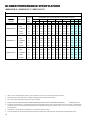
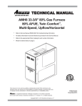
BLOWER PERFORMANCE SPECIFICATIONS
GME80603B*A*, GME80805C*A*, GME81005C*A*
(CFM & Temperature Rise vs. External Static Pressure)
Tons AC
Model
Heating Speed
As Shipped
GME80603B*A*
GME80805C*A*
GME81005C*A*
1.
Motor Speed
at 0.5"
ESP
EXTERNAL STATIC PRESSURE (Inches Water Column)
0.1
0.2
0.3
0.4
0.5
0.6
0.7
0.8
CFM RISE CFM RISE CFM RISE CFM RISE CFM RISE CFM CFM CFM
T1 - YELLOW
1.5
875
59
793
65
736
70
674
77
592
88
556
509
460
T2 - RED
2.0
1032
50
965
54
914
57
861
60
810
64
756
712
659
918
877
T3 - ORANGE
2.5
1217
43
1153
45
1098
47
1051
49
1009
51
964
T4 - BLUE
3.0
1365
38
1313
39
1268
41
1221
42
1172
44
1129 1086 1054
T5 - BLACK
3.5
1549
33
1505
34
1460
36
1420
37
1378
38
1350 1305 1268
T1 - YELLOW
2.5
1268
53
1198
56
1151
58
1092
61
1041
64
988
T2 - RED
3.0
1362
49
1305
51
1261
53
1212
55
1170
57
1121 1074 1021
T3 - ORANGE
3.5
1576
42
1519
44
1473
45
1426
47
1398
48
1341 1290 1252
T4 - BLUE
4.0
1755
38
1711
39
1657
40
1627
41
1579
42
1548 1502 1463
T5 - BLACK
5.0
2183
31
2128
31
2094
32
2060
32
2014
33
1992 1944 1847
932
883
T1 - YELLOW
3.0
1466
58
1415
60
1357
63
1306
65
1248
68
1202 1144 1088
T2 - RED
3.5
1642
52
1596
53
1552
55
1499
57
1449
59
1388 1352 1306
T3 - ORANGE
4.0
1750
49
1750
49
1707
50
1667
51
1610
53
1574 1531 1486
T4 - BLUE
4.0
1870
46
1805
47
1782
48
1737
49
1701
50
1656 1606 1571
T5 - BLACK
5.0
2297
37
2297
37
2224
38
2106
40
2014
42
1896 1813 1669
CFM in chart is without filters(s). Filters do not ship with this furnace, but must be provided by the installer.
2.
All furnaces ship as high speed cooling. Installer must adjust blower cooling speed as needed.
3.
For most jobs, about 400 CFM per ton when cooling is desirable.
4.
INSTALLATION IS TO BE ADJUSTED TO OBTAIN TEMPERATURE RISE WITHIN THE RANGE SPECIFIED ON
5.
The chart is for information only. For satisfactory operation, external static pressure must not exceed value shown on rating plate. The shaded area
indicates ranges in excess of maximum external static pressure allowed when heating. The data for 0.6" w.c. to 0.8" w.c. is shown for air conditioning purposes only.
6
The dashed (---) areas indicate a temperature rise not recommended for this model.
7.
A properly derated unit will have approximately the same temperature rise at a particular CFM, while the ESP at that CFM will be lower.
14
THE RATING PLATE.
BLOWER PERFORMANCE SPECIFICATIONS
GME8
(C F M & T e mp erat u re R is e v s. Ex te rn al St atic Pre ss u re)
H ea ting Sp ee d
As Sh ip pe d
G M E 8 0 6 0 3 B ** *
G M E 8 0 8 0 5 C* **
G M E 8 0 8 0 5 D* **
(M E D-H I)
G M E 8 1 0 0 5 C* **
E X T ER N AL ST AT IC P R E SS U R E (Inch es W a te r C o lu m n )
T on s A C
Mo de l
M o to r S pe ed
at 0.5"
ES P
0.1
0.2
0 .3
0 .4
0 .6
0.5
0.7
0 .8
C F M R ISE C F M R IS E C F M R IS E C F M R ISE C F M R ISE C F M C F M C F M
T 1 - YE LLO W
1 .5
875
----
793
----
736
----
674
----
592
----
556
509
460
T 2 - RE D
2 .0
1032
43
965
46
914
49
861
----
810
----
756
712
659
T 3 - O RA N G E
2 .5
1217
37
1153
39
1098
40
1051
42
1009
44
964
918
877
T 4 - B L UE
3 .0
1365
33
1313
34
1268
35
1221
36
1172
38
1129
1086
1054
T 5 - B L A CK
3 .5
1549
29
1505
30
1460
30
1420
31
1378
32
1350
1305
1268
T 1 - YE LLO W
2 .5
1268
47
1198
49
1151
51
1092
54
1041
57
988
932
883
T 2 - RE D
3 .0
1362
44
1305
45
1261
47
1212
49
1170
51
1121
1074
1021
T 3 - O RA N G E
3 .5
1576
38
1519
39
1473
40
1426
42
1398
42
1341
1290
1252
T 4 - B L UE
4 .0
1755
----
1711
35
1657
36
1627
36
1579
38
1548
1502
1463
T 5 - B L A CK
5 .0
2183
----
2128
----
2094
----
2060
----
2014
----
1992
1944
1847
T 1 - YE LLO W
3 .5
1524
39
1479
40
1439
41
1388
43
1343
44
1281
1243
1190
T 2 - RE D
4 .0
1683
35
1646
36
1607
37
1569
38
1531
39
1488
1441
1395
T 3 - O RA N G E
4 .0
1884
31
1832
32
1849
32
1765
34
1724
34
1692
1661
1626
T 4 - B L UE
4 .0
1951
30
1904
31
1879
32
1842
32
1803
33
1768
1734
1687
T 5 - B L A CK
5 .0
2036
29
2010
29
1977
30
1947
30
1923
31
1888
1844
1816
T 1 - YE LLO W
3 .0
1466
51
1415
52
1357
55
1306
57
1248
59
1202
1144
1088
T 2 - RE D
3 .5
1642
45
1596
46
1552
48
1499
49
1449
51
1388
1352
1306
T 3 - O RA N G E
4 .0
1750
42
1750
42
1707
43
1667
44
1610
46
1574
1531
1486
T 4 - B L UE
4 .0
1870
40
1805
41
1782
42
1737
43
1701
44
1656
1606
1571
T 5 - B L A CK
5 .0
2297
----
2297
----
2224
----
2106
35
2014
37
1896
1813
1669
N o te s:
• C F M in cha rt is w it ho ut filt er ( s). F ilter s d o not sh ip w it h this f ur na ce, bu t m u s t b e p ro vide d b y th e in stalle r. If the fu rn ac e r eq uir es t wo
r et ur n f ilt er s , t his c h ar t a ss u me s b oth filte rs ar e in sta lle d.
• A ll fu rn ac e s ship as hig h- s pe ed c oo lin g and m ed ium - spe ed he atin g. Inst aller m us t a djust blo we r c oo lin g a nd he at in g s pe ed as nee de d.
• F o r m ost jobs , a bou t 3 75 - 40 0 CF M p er to n w h en coo lin g is de s ir a ble.
• I N ST AL LA T IO N IS T O BE AD J U ST ED T O O B TA IN T E MP ER AT U R E R IS E W I T HI N T HE R AN G E SP EC IF IE D O N T H E RA T IN G P LAT E .
• T h is ch ar t is f or inf or m ation o nly. F or s a tis fac tor y o per a tion , e xt er na l sta tic pr e s sur e sh o u ld n ot ex ce ed v alue sh ow n o n the r atin g p late .
• A p ro pe rly d er at ed un it w ill h ave ap pr oxim at ely th e s am e tem p er atu r e r is e at a p ar tic ula r CF M , w h ile ES P a t t he C F M w ill be low er .
• F a cto ry Mo tor S pe ed Se tting : T 1 = 1s t S tag e H t , T 2 = 2n d S tag e Ht , T 5 = C oo lin g.
• T e m pe ra tur e rise da ta is b as e d o n 2 nd -s tag e h ea t. F irs t -s t ag e h ea t is 7 5% of rise ind ic ate d a bo ve.
15
16
10
20
30
40
30
50
60
70
80
90
100
40
50
60
700
600 CFM
90
100
2000
2200
2400 CFM
1800
1600
1400
OUTPUT BTU/HR x 1000
80
1200
1100
1000
900
70
800
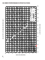
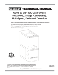
FORMULAS
110
120
130
140
BTU OUTPUT = CFM x 1.08 x RISE
BTU OUTPUT
RISE =
÷ CFM
1.08
BTU OUTPUT vs TEMPERATURE RISE CHART
150
BLOWER PERFORMANCE SPECIFICATIONS
TEMPERATURE RISE
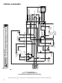
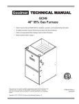
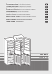
WIRING DIAGRAMS
GME80603B***/GME80805C***/GME81005C***
WARNING:DISCONNECTPOWERBEFORE
SERVICING.WIRINGTOUNITMUSTBE
PROPERLYPOLARIZEDANDGROUNDED.
INTEGRATED
CONTROLMODULE
HUMIDIFIER
XFMR(6)
GND
GND(8)
24 VAC
HUMIDIFIER
C2
MVC(9)
HI
MVH(12)
MVL(2)
C
GAS
VALVE
M1
IDBLOWER
PRESSURE
SWITCH
AUXILIARY
LIMITCONTROLS
G
R
W
LY
GD
ST
Y
D
5MIN
2N
2STG
MODE
100SEC HTO
FFD
LY
AUTO
1STG
150SEC
10 11
12
8
9
4
5
6
1
2
3
WH
BL
DIAGNOSTIC
LED
7
FUSE
SEE NOTE6
BR
FS
RD
RD
PS(10)
W
HLO(1)
AUTORESET
PRIMARY
LIMIT
CONTROL
R
RO2(11)
RO1(5)
MANUALRESETROLLOUT
LIMITCONTROL(S)
(SINGLECONTROLONSOMEMODELS)
24VAC
40VA
TRANSFORMER
BR
COOL-H LO HEAT-H
PU
OR
LINENEUTRAL
YL
1
XFMR-H
XFMR-N
115VAC
FLAMESENSOR
FP
HOTSURFACE
IGNITER
XFMR-H LINE-H EAC-H
24V
BL
CIRCULATOR
BLOWER
BR
115V
WH
XFMR
WH
IGN-N
ID
BLWR
IND
IND-N
HE LO
AT
-H
COOL-H CIRCULATOR
BLWR
HI -H
AT
HE
BK
15PINPLUG
ONSOMEMODELS
GR
EAC-H
BLOWERCOMPARTMENT
ELECTRONIC
AIRCLEANER
LINE-N
JUNCTIONBOX
WH
BK
NO
C
OR
RD
RD
DOOR
SWITCH
24VAC
HUMIDIFIER
DOORSWITCH
WH
WH
YL
PRIMARYLIMIT
EAC-N
LINE-H
BURNERCOMPARTMENT
SWITCHLOCATEDINBLOWER
COMPARTMENTONSOMEMODELS
CIR-N
INTEGRATEDCONTROLMODULE
WH(N)
BK
INTEGRATEDCONTROLMODULE
BK(HI)
BL(MEDHI)
OR(MED)
RD(MEDLOW)
YL(LOW)
PU
WH
IGN
PARK
BK
NO
C
PSO(4)
TO
MICRO HLI(7)
Y
XFMR(3)
BL
RD
YL
HIGH VOLTAGE!
DISCONNECT ALL POWER BEFORE SERVICING OR INSTALLING THIS
UNIT. MULTIPLE POWER SOURCES MAY BE PRESENT. FAILURE TO
DO SO MAY CAUSE PROPERTY DAMAGE, PERSONAL INJURY OR DEATH.
AUXILIARY
LIMITS
G
HI HEAT-H
INTEGRATED
CONTROLMODULE
2
24VTHERMOSTATCONNECTIONS
C
PRESSURE
SWITCH
YL
RD
YL
YL
WH
WARNING:
DISCONNECTPOWER
BEFORE SERVICING.
WIRINGTOUNIT
MUSTBE
PROPERLY
POLARIZED
ANDGROUNDED.
BK
DISCONNECT
L
GND
N
BR
BL
OVERCURRENTPROTECTIONDEVICE
WH
PM C
1
3
HOT
SURFACE
IGNITER
HI
2
BK
JUNCTION
BOX
WH
2STAGE
GASVALVE
(HONEYWELL)
LINE-N
GND
LINEH
PU
INDUCEDDRAFT
BLOWER
PU
PU
FLAME
SENSOR
ROLLOUTLIMITS
(SINGLECONTROLONSOMEMODELS)
0
STEADYON=NORMALOPERATION
1
1FLASH =
2
2FLASHES=PRESSURESWITCHSTUCKCLOSED
3
3FLASHES=PRESSURESWITCHSTUCKOPEN
4
4FLASHES=OPENHIGHLIMIT
5
5FLASHES=FLAMESENSEWITHOUTGASVALVE
6
6FLASHES=
7
7FLASHES=LOWFLAMESIGNAL
8
8FLASHES=CHECKIGNITERORIMPROPERGROUND
C
RAPIDFLASHES=REVERSED115VACPOLARITY/VERIFYGND
OFF
LOW VOLTAGE (24V)
=CONTROLFAILURE
COLORCODES:
YL YELLOW
OR ORANGE
PUPURPLE
GRGREEN
BKBLACK
SYSTEMLOCKOUT(RETRIES/RECYCLESEXCEEDED)
LOWVOLTAGE FIELD
HIVOLTAGE (115V)
EQUIPMENTGND
FIELDGND
FIELDSPLICE
HIVOLTAGE FIELD
SWITCH(TEMP.)
OPENROLLOUTOROPENFUSE
PKPINK
BRBROWN
WH WHITE
BLBLUE
GYGRAY
RD RED
TO115VAC/1/60HZ
POWERSUPPLYWITH
OVERCURRENTPROTECTION
DEVICE
JUNCTION
TERMINAL
INTERNALTO
INTEGRATEDCONTROL
PLUGCONNECTION
IGNITER
SWITCH(PRESS.)
OVERCURRENT
PROT. DEVICE
NOTES:
1.SETHEATANTICIPATORONROOMTHERMOSTATAT0.7AMPS.
2.MANUFACTURER'SSPECIFIEDREPLACEMENTPARTSMUSTBEUSEDWHENSERVICING.
3.IFANYOFTHEORIGINALWIREASSUPPLIEDWITHTHEFURNACEMUSTBEREPLACED,ITMUSTBEREPLACED WITH
WIRINGMATERIALHAVINGATEMPERATURERATINGOFATLEAST105°C.USECOPPER
CONDUCTORSONLY.
4.BLOWERSPEEDSSHOULDBEADJUSTEDBYINSTALLERTOMATCHTHEINSTALLATIONREQUIREMENTSSOASTO
PROVIDETHECORRECTHEATINGTEMPERATURERISEANDTHECORRECTCOOLINGCFM.(SEESPECSHEETFORAIR
FLOWCHART)
5.UNITMUSTBEPERMANENTLYGROUNDEDANDCONFORMTON.E.C.ANDLOCALCODES.
6.TORECALLTHELAST5FAULTS,MOSTRECENTTOLEASTRECENT,DEPRESSSWITCHFORMORETHAN2SECONDS
WHILEINSTANDBY(NOTHERMOSTATINPUTS).
0140F00658 REV.A
Wiring is subject to change. Always refer to the wiring diagram on the unit for the most up-to-date wiring.
17
18
IGNITOR
FP
K3
LO
HEAT
IGN
.0005
3M
K2
K1
FLAME
SENSOR
PROBE
K3
K2
HI
COOL HEAT
CIRCULATOR
BLOWER
K4
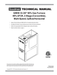
TYPICAL SCHEMATIC
GME8 ____** MODEL FURNACES
WR 50M56-289 INTEGRATED IGNITION CONTROL
Wiring is subject to change. Always refer to the wiring diagram on the unit for the most up-to-date wiring.
HI
PM
COM
MV
2-STAGE
GAS VALVE
GND
MLV
FACTORY
JUMPER
CIR
PARK NEU EAC
PS
K5
IND
INDUCER
PRESSURE
SWITCH
HIGH
LIMIT
HLO
FACTORY
JUMPER
K6
EAC
NEU
ELECTRONIC
AIR CLEANER
AUX
LIMIT
HLI
K7
HIGH VOLTAGE!
DISCONNECT ALL POWER BEFORE SERVICING OR INSTALLING THIS
UNIT. MULTIPLE POWER SOURCES MAY BE PRESENT. FAILURE TO
DO SO MAY CAUSE PROPERTY DAMAGE, PERSONAL INJURY OR DEATH.
PSO
Y
G
W
XFMR
NEU
TR
C
XFMR
HOT
TH
RO2
RO1
R
Y
G
W
R
THERMOSTAT
COMPRESSOR
CONTACTOR
COIL
24 VAC
ROLLOUT
SWITCH
WIRING DIAGRAMS