1
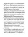
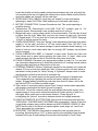
BRIDGESTONE GTR 350 TECH-TIPS “LESSONS LEARNED” The intended use for this article is to guide those with little or no experience working on the GTR 350. These motorcycles are very unique in design, and in my opinion one of the best made bikes from the 60’s. These are my “EXPERIENCES” (from completely restoring a Bridgestone GTR 350). To write this I utilized my 40 + years experience working on and riding various brands of motorcycles but DO NOT consider myself an expert on the GTR 350, only offering the following advise with (no warrantees are guaranteed or implied!) For an excellent source of parts and more detailed information visit Richards Relics at (http://www.bridgestonemotorcycleparts.com). The site provides access to a great group of people dedicated to bringing Bridgestone’s back to life. From there you can download Parts/Service Manuals and just about anything you need to bring one of these classics back to life. For some photos pertaining to this article visit my photo gallery on Richards Relics (my user name is RIDERED). Again this is not intended to be a complete how to article only my personal experiences. THINGS TO LOOK FOR WHEN PURCHASING A GTR FOR RESTORATION: 1. BATTERY BOX AREA: Check for modifications to utilize the wrong size battery. The GTR used an odd sized battery that was probably hard to get your hands on back in the day before the internet, so it’s inevitable that mods were made in that area to go riding for the day. For the correct size battery I used one from batterystuff.com part number YT5AL and it fit just a little snug but no mods required. 2. REAR BRAKE PEDAL: Check stop and spring catch to make sure it isn’t broke off or bent as you will want to repair this before powder coating. 3. ENGINE CASES: Check for cracks or damage, especially in the area of the rubber frame mounts. If ridden long with bad rubber mounts cases will get chewed up in these areas. Not a huge problem to fix but will add cost and time to the project. 4. CHAIN GUARD: Check for cracks or missing. This is a hard item to find in decent useable condition. 5. CHROME PARTS: Inspect well for excessive pitting. If you have to add Acid Copper to your chroming process later to smooth out the pits it will add a lot of extra weight/cost and may cause some items not to fit properly. 6. ENGINE: Check to see if it is froze up. The problem here is these cylinders are cast aluminum with chrome bores and hard to find if damaged. Check exhaust flange area for cracks or repairs as I have seen this area welded from being hit to hard trying to remove the cylinder. These bores can be repaired by Nicasil plating for about two hundred per cylinder if no welding is required to repair gouges in the aluminum bore. I recommend US Chrome Corporation of Wisconsin for this work, they included cleaning the cylinders aluminum finish in the price and they really looked good. 7. FRAME: Check the frame for major rust or cracks. If frame rust is bad enough when you blast it for powder coating there will be pits, I’m not sure how you can repair them before power coating. In this case for a smooth finish I would consider conventional painting where you can smooth out the pits with body filler prior to painting. Check the neck and front down tubes for straightness. This bike was 1 designed for right or left side brake/shifter set-up, make sure the tabs for left side brake have not been removed from frame. 8. WHEEL HUBS: Check the front and rear for wear in the area of the spokes exiting the hubs, as this can be caused from riding with loose spokes. Check area around rear sprocket for damage from bad rubber dampers. 9. GAS TANK: Check for dents as the entire tank requires chroming prior to painting and you don’t want dents. The good thing is the outer shell of the tank is pretty thick to resist denting. The inner or under side of these tanks are thinner so pin holes can be a problem. This can be fixed utilizing a liner AFTER the chroming process has been done. Part of the chroming process is to remove all the rust from the tank, that usually gets the inside cleaned out for you. For tanks that don’t need re-chroming just need the inside cleaned I recommend EVAP-O-RUST from Harbor Freight this is an Eviro friendly product that won’t damage paint like harsh chemicals and works really good for removing rust. I don’t shy away from rusted tanks anymore. Before chroming the tank run a bead of weld around where the petcock stub comes thru the tank as this is a weak point in the design, it can spin loose from over tightening the pet cock nut. 10. INJECTION OIL TANK: Look on the backside in the area where it mounts to the frame if you see oil it’s most likely cracked around the mounting points. In any case test it for leaks prior to painting. 11. FINAL NOTE: A lot of the items mentioned above are not to scare someone away from a project it’s just better to know what you’re getting yourself into before you start. I personally prefer restoring a bike that looks impossible to fix as I get more satisfaction knowing I saved a classic piece of history from distinction. The problem with my way of thinking is if you’re doing it to make money “FOR GET IT” you can buy a restored bike for a lot less. GOOD LUCK let’s get started! CLEANING TIPS PRIOR TO DIS-ASSEMBLY: 1. Use a good degreaser and pressure washer to remove as much of the dirt and grime as possible. 2. Drain all fluids. This process usually unveils some more Demons. 3. When draining engine oil examine color and look for pieces of steel or aluminum as this could warn you of bad things to come. If oil is grayish water/moisture has entered the motor. If pieces of metal come out you’ve been warned. 4. Drain Oil injection tank, make note of any internal problems that need attention later, such as cracks/leaks. The steel inside should be ok as the 2-cycle oil usually preserves it. 5. Drain Front forks from the small Phillips screws at the fork leg bottoms. Be careful as these are small and can strip or break easily. 6. Drain fuel from tank, if it’s still in the liquid state!!! Use lacquer thinner for “just gunk / old gas” (keep sloshing & letting it sit & sloshing & flushing until clear) or lacquer thinner with nuts & bolts for rust. Highly recommend EVAP-O-RUST from Harbor Freight for final rust removal from the inside of tank. DISASSEMBLY: 1. Start by taking a lot of pictures and notes of cable and wiring harness routing and all electrical component locations. Termination points of ground wires ETC! ETC!. 2 2. Keep relevant parts together in heavy duty plastic Ziploc bags. Use magic marker for making notes on them. 3. Remove the engine first as it’s the heaviest item to get out of your way. 4. Remove all electrical components. 5. Remove wheels; remember to keep all relevant parts together. 6. Remove forks/front end and associated items. 7. Remove rear shocks, rear fender. 8. Remove remaining small items such as side stand rear brake pedal ETC!! 9. NOTE: As I remove an item I like to put the fasteners in separate bags and mark what they were for. Later you can measure the thread length, bolt/nut head size and list what it was for, this will be helpful later. Remember when they go off for zinc plating they will all get mixed together. ENGINE TECH-TIPS "LESSONS LEARNED” Utilize the parts manual for exploded pictorials of how things go together. Use the service manual for instructions. The service manual is pretty vague in some areas so remember take plenty of pictures. I especially like the areas in the manual where it tells you to reassemble in the reverse order of disassembly. You got to love reading that on a first time build. 1. UN-SEIZING PISTONS (This is based upon input from a number of sources): Start by using a mix of Marvel Mystery oil and penetrating oil. Pour into the spark plug port or open cylinder heads. You can also put in Kroil penetrating oil for a few hours, to REALLY “soak & loosen things up”. 2. BEARING RETAINERS: for the crankshaft and two gear shafts are all different sizes so make sure they are installed correctly. 3. SHIFTING: Before putting gear shafts back in verify shift forks are operating correctly. I say this because when you drop the shafts in with the gears it won’t shift thru all the gears easily you’ll have to shift it as your spinning the shafts. You can check that it’s shifting properly by watching the notch on the left side of the shift drum turn before installing the neutral switch case. 4. NEUTRAL SWITCH CASE: Make sure the transmission is in neutral install so the contact point in housing lines up with contact on end of shift drum. You can also check by 5TH gear. 5. CAUTION! The drive pinion nut on the right side of crank is left hand thread; you don’t want to damage this nut or the crank threads. 6. KICKER INSTALLATION: To get the kick start ratcheting correctly remove the snap ring from the left side of shaft. Then install kick start lever temporally. Push the shaft in as your kicking it down, push it back to the left before you let up on the lever. Kick start idle gear should turn and kick lever should have good spring tension to it when installed correctly. 7. SPECIAL TOOL REQUIRED: You will need to make or buy a tool for removing and installing the 40 MM ring nut on the clutch basket. Let your imagination run wild here or do as I did and cut a piece of pipe to work. Recommend using some Loctite on 3 the threads for both clutch basket/hub nuts for extra security even though they both have washers with locking tabs. 8. CLUTCH: There were 3 different clutch setups using various configurations see page 21 of the service manual and Bridgestone service letters BSG-0060 and BSG0061 for the different setups. This can be very confusing so review the different configurations closely. When assembling the clutch pack pay special attention to the metal band that wraps around the clutch basket fingers as it has a tendency to get cracks and breaks in it. 9. TIMING GEAR: Make sure the woodruff key on the end of dynamo is in perfect shape no signs of shearing as this is critical for engine timing. 10. CYINDER INSTALLATION: Ring gaps are lined up with the pins in the piston. Marking near ring gap faces up. EX on piston faces forward. For ease of installation install the piston with rings in the cylinder before lowering it down on the studs. Be sure to install the piston pin circlip first that faces the inside (center of engine). Install bearing in the rod push piston pin in just till it comes thru the first side of piston lower cylinder down till pin lines up with rod push pin thru the rest of the way and install other circlip. Push cylinder down till it’s flush with engine case. Repeat for other cylinder. This method makes it easier to line up ring gaps with the piston pins and eliminates the chance of cracking a ring. 11. POINTS CAM: Ensure the FELT pad that lubricates the point’s cam is oiled periodically. Otherwise, point lobes will wear excessively!! Marvel Mystery Oil or engine oil works fine - suggest a minimal re-lube every 500 miles. 12. TUNE UPS: Points and timing adjustment are detailed in the Bridgestone service manual. There is a special tool to stop the crank at the point when the points should open. Just below the base of the left cylinder you will see the bolt that needs to be removed. This bolt is different between production years. Early models had 8 MM threads and later years had 6 MM. For the later years you can utilize the chain adjuster bolt to lock the crank in position. Mine is the 8 MM version so made a tool from an old clutch cable adjuster, light spring from an inner tube valve stem and a screw so it is spring loaded to snap into the indention on the crank. When the left piston is nearing TDC and your tool snaps in the indention the left points should just start to open. Rotate till right piston is nearing TDC and pin will stop crank where right points should start to open. I use an audible meter for this process. When reinstalling the bolt, make sure the fiber washer is in good shape, you don’t want a air leak here as it’s a direct shot to the left combustion chamber. 13. NOTE: I have heard that the special crank holder tool comes with the GTR 350 tool kit but personally have never seen one. But as described above you can make one with very little effort. 14. SPARK PLUGS: Use B8HS in lieu of the old Number B-8H. 15. CARB ADJUSTMENT: See Service Manual for detailed info. I could write an entire article on this subject alone so I will only mention the basics at this time. Carb main jet size (#140 std. .... at sea level), Operation at higher altitude necessitates the use of a lower numbered jet (#130). Pilot air screw should be approximately 2 turns out. Always verify float height is set correct before attempting to trouble shoot Carb problems. The air screw and slow jet governs the mixture from 0 to 1/4” throttle openings. The Jet Needle effects mixture from 1/4” to 3/4” throttle openings The 4 Main Jet governs the mixture from 3/4” to full throttle. To lean out the mid range, lower the jet needle further down into the throttle valve (or slide), raising it richens the mixture. 16. CHECK "SYNCH" between throttle slides for probable cause of "popping" noise at idle. You want a "VERY slight" lag in throttle response before the slides rise. You don't want the throttle cables taught / too tight! Check that there are no hang ups or binding on the cables when viewing the slide operation (Synch the throttle cables by the “O” stamped on each carb slide) See Bridgestone service manual for detailed info on carb and oil pump synchronization. 17. THROTTLE, CHOKE & OIL PUMP CABLE INSTALLATION: This can be very time consuming unless you are a master at putting puzzles together. Route throttle and choke cable junction tubes between the right and left coils add a tie strap there. Next run one throttle and choke to the left carb and one each plus the oil pump cable to the right. Next put the cables thru a cable spring on each side. Next add the carb rubber adjusting cap to the throttle cables. Next put the cables thru the rubber carb caps on each side. Next add the slide assemblies to throttle cable and install them in the carb so you can see the “O” from the air side. Slide the rubber carb caps up a little to get room to install the choke assembly in the carb. Next push the rubber carb cap down till it’s flush with the carb top and slide the whole assembly onto the rotary valve covers. Sounds easy enough but for some reason it took me several tries to get all the parts on in the right order! (THAT DARN PUZZLE THING AGAIN). 18. CHOKE CABLE ADJUSTMENT: It’s very important that the choke plungers are seating (BOTTOMING OUT) in carbs. To check spray some WD 40 around the cable where it goes thru the rubber carb cap and pull up and down on the cable there should be 1/16” free play. Engine will run rich if this procedure is not correct. The choke lever should have at least an inch of motion. 19. COMPRESSION CHECK: Compression should be 121-135 psi. Ensure the throttle is “wide-open” when testing compression. Also test for compression “bleed down” to get a TRUE sense of the condition of your rings, integrity of the cylinder barrel. As long as the difference is less than 10+/-% side-to-side, and over 120 psi, there is “NO compression problem”. Many factors cause the compression difference such as thickness of head gasket, piston shape/consistency from right to left, ring seating. 20. ORIGINAL AIR FILTERS: Use the screen only, install some modern day foam so the air passes thru the foam then the screen on its way to the carb and remember to use some light oil on the foam. FRAME ASSEMBLY TECHTIPS "LESSONS" LEARNED” 1. NEW BARS: File the rough “inner” edges of NOS bar at the "internal wiring cutouts. Otherwise possibly damage to the wires can occur later on down the road. 2. HEADER (Exhaust) PIPES: To prevent Bluing & "Heat Discoloration" of pipe exterior, wipe down with brake cleaner or equivalent to remove all oil residues. 3. CABLE ROUTING: Clutch, Tach and electrical wiring on left side and Throttle and choke cable on right side – ALL ABOVE the (frame) tank mounts. Throttle cable travels in front of right upper fork ear (you adjust the position of the metal “elbow” below the throttle handle so that the cable runs just "FWD" of the right fork ear), 5 locate the throttle and choke cable junction boxes between the coils and verify the coil mounting bolts are not binding the cable junction boxes. Make sure the throttle and choke cables are "seated" into the carb tops. 4. SPEDO AND TACH CABLES: Verify they are "seated" in drive-ends before tightening by hand (CAUTION: Cable ends are pot metal and crack easily). 5. BATTERY CONNECTION: Connect Ground wire last. This avoids sparking or possible shorting. 6. Transmission Oil: Recommend Lucas SAE 75-90 WT synthetic gear oil. For injection system: Recommend Lucas synthetic ash less 2-cycle oil. 7. Bridgestone uses a unique oiling system for the transmission. The left side oil level is higher than the right. Make sure you have the correct oil drain bolt, should be 7/8” thread length. If it’s too short the oil levels will equalize NOT GOOD. See page 19 fig 45 of service manual for clarity. 8. CHAIN ADJUSTMENT: Note that "testing" chain adjustment should be done when weight is "on the seat" and bike is "off" the center stand!! Also, DO NOT “over tighten” the axle bolts! Can cause damage to spacer between wheel bearings. It is better to have too much chain slack than not enough (3/4" between up and down travel is normal). 9. CHAIN LUBRICATION: BEST to “lubricate” a warm chain. Ensure the chain has been driven and is warm before applying the chain lube. A “warm” chain more readily accepts the lube and lets it flow into the roller joints and niches. 10. CHAIN CLEANING: Kerosene is an appropriate medium to soak it in. You can also use a kerosene dampened rag to clean the external dirt off, making several passes along the chain and using a clean portion of the rag. 11. STEERING DAMPER: Advise a "tightened" damper for the freeway, but loosen the damper 2/3 turn (so that front wheel just "falls" of center position on main stand w/ rear wheel on the ground) for "twisty" driving. A "tightened" damper tends to make the bike want to stand-up and travel in a straight line. 12. ELECTRICAL: All contact points on the frame must be cleaned of powder coat. This is especially true regarding the rectifier (at frame), taillight assembly (at fender). Suggest adding a braided ground strap from motor to frame, due to the fact that the GTR is a rubber mounted engine. 13. Take caution in connecting wires (ensure “bare” metal to metal contact especially with powder coated parts and avoid ground-to-power!!). 14. TAILLIGHT: Check the contacts inside the rear taillight bulb holder socket (on a regular basis) as it can cause intermittent electrical contact (diming of bulb or no stop light). Main culprit here is rear fender vibration. Check this prior to investigating the "ground" connection between fender and taillight assembly. 15. CHECK NUTS/BOLTS & COTTER PINS: Ensure that all nuts and cotter pins are THROUGHLY CHECKED AND TIGHTENED after re-assembly. Failure of the front or rear brake stopper arms could be disastrous (AND POSSIBLY DEADLY)!! Also NOTE that the use of Anti-Seize on (spoke nipples, spark plugs, etc.) and LockTite is appropriate for some items. 16. SPROCKET TIGHTENING: After break-in recheck the rear sprocket nuts for loosening. Sprockets take a “LOT” of abuse as they are constantly being stressed between full torque & hard braking! Ensure both are checked for “tooth” wear 6 (generally appears as “cupping” on one side of the teeth) The latter requires replacement (including the front drive sprocket locking flange). NOS replacements work BEST. A “loose” rear sprocket usually requires only re-torque of the 6-nuts that secure it to the rubber dampers. 17. Replacement of the front drive sprocket is least expensive, and has the most beneficial effect on extending the life of the rear sprocket & chain. 18. HANDLE BAR CLAMPS: Are installed with the “tallest” portion toward the front. Tighten front bolt first, then “snug-up” the aft bolt on each side. This procedure ensures the Bar is SECURELY fastened in place with no chance of coming or working itself loose. 19. THREAD CLEANING: Clean bolt holes prior to assembly. Use a .22 caliber wire brush with cleaning rod this works well for "reaming out" screw / bolt holes (and not damaging threads). Another option regarding cleaning of excess powder coat or paint from bolt holes is to use a metric thread tap kit. 20. FASTENERS: Care to be taken with fasteners as Bridgestone used different pitch threads, air cleaner housing for example. Front axle pinch bolt has a dimple in the center and uses a 13 MM wrench to tighten. “VERY ODD” 21. LOWER FORK LEGS: Run a hone thru the left leg axle hole as you want it to move freely on axle before tightening pinch bolt. Clean & remove all minor rust deposits with (0000 steel wool) from the chrome fork tubes. 22. FRONT FENDER MOUNTING: Make sure to use the correct (length) bolts, too long could damage the lower leg and bind the fork slider. 23. FORK OIL CAPACITIES: 7.5 oz for each leg (DRY). I use Synthetic 10 WT fork oil. 24. There are nice reproduction fork boots available. They come without the air vent holes so make sure you drill the two 1/8” diameter holes needed to vent air. This will prolong the fork boot life. (Use old fork boots for hole locations). 25. WHEEL BEARINGS: Removal of grease from the bearings without replacement can be done by removing the plastic seal on the bearing with a pointed awl. Clean out old grease repack and replace plastic seal. Regarding scoring or wear marks on the axles or pivot bolt, use 0000 steel wool to remove burs / rust and smooth rough surfaces is recommended. If axle wear (at the point of contact) with the bearing surface is severe, the axle should be replaced. Replacement of the swing arm pivot bolt (due to scoring or wear) is far less likely, but bushings should be replaced if any side to side movement can be felt after tightening the pivot bolt. 26. TIRES: I used Avon’s (front) Speedmaster MK11 3.25-19 (rear) Safety Mileage MK11 350-19 Dennis Kirk had the best prices by far on the tires. 27. Seat: Pit Replica makes a real nice cover that fits perfect. For the seat buttons I used Sirius Consolidated Inc in Canada they seemed to be the closest to the originals. 28. PAINT/ZINC: The side stand and front foot peg mounting brackets are zinc plated. For the painted silver items such as the outer engine cases, taillight housing and lower fork legs I used Aluma Blast from the Eastwood Company and coated with a good quality clear. 7 STORAGE PROCEDURES "LESSONS" LEARNED” 1. STORAGE PROCEDURES: (3 thru 6 months) fill gas tank with “new” gas and use "Stabilizer". Drain and clean petcock and carb (squirt with WD40); drain and fill crankcase with new oil. Remove the battery. ( 6 months or longer) clean the whole bike (use a good Protectorate); drain & flush (use mineral spirits or kerosene) for gas tank (& spray inside w/ rust inhibitor or "WD40"); Follow the 3 to 6 month steps for carbs, petcock, battery, and crankcase. 2. BATTERY CHARGING: Recommend a "battery tender" that produces a decreasing voltage charge, and drops to "0" when the battery is fully charged. 3. The tenders come in either 6 or 12 volt. An inexpensive, "low-voltage tricklecharger" is also useful. Use of a“tender” insures a full charge "when needed" & does not require removal from bike during short term storage. 4. Install a "battery tender" tether on your battery to allow for "trickle" charging with battery in the bike. “Trickle” is so minimal that it won’t harm the bike’s electrical system. ACKNOWLEDGEMENTS A special Thanks to Richard Clark and all the Admin staff for maintaining (Richards Relics Bridgestone). I would especially like to thank the members of Richards Relics Bridgestone site for all the informative posts that helped me along the way with this build. All the people that helped me source the massive amount of parts I needed. Too many names to list but you all know who you are. For those rare and hard to find parts check out Kevin at Scrambler cycle he seems to have parts most folks don’t want to let go off and a great person to deal with. For Carburetor ultrasonic cleaning check out Steve Reed at Carb Worx 540 588-0007 Great to deal with and a lot of technical knowledge on various machines Chroming, Speed & Sport chrome plating Houston, Texas 713-921-0235 asks for Craig. A great person to do business with. That makes all the difference in the world before handing rare motorcycle parts to someone; He stands behind his work 100% and is very reasonable on pricing. In closing I hope this article helps someone save a little time and money on their GTR build. RIDERED (The Red Rider) Mike Weiland 8 9