1
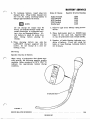
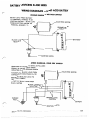
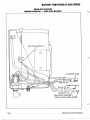
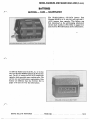
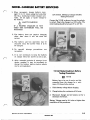
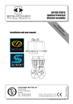
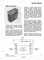
THEORY OF OPERATION
Secondary, orstorage, cells have reversibleactions
known as "charge" and "discharge." A storage
cell
must
first be
charged by sending a current throughthe
an outsidesource.
positiveterminalfrom
On discharge,currentpasses
throughthe
cell in an opposite direction.
When the cell
provides a current, or discharges, it simply
reversesthechemicalreactionthattakes
place' during the charging period. An elec-*
triccurrent(chargecurrent)replacesthe
lostchemicalenergybeforethecyclecan
s t a r t again.
A batteryproducesanelectriccurrent
by
chemicalaction. A battery consists of one
ormoreunitscalled
“cells.” Cells may
bedividedinto
two classes:primary
and
secondary
(storage).
Cells used in flashlights, hearing aids, and
portableradios
areprimary
cells.They
produce an electric current because of materials used in their construction. When all
the chemical energy has been converted into
electrical energy, the cell can no longer be
used until new materials are added.
POSITIVE-
PLATE
FIGURE 1
in Lawn-Boy
Thelead-acidbatteryused
1.)
mowersconsists
of six cells.(Figure
The atoms in the electrolyte are neutral because they have an equal number of positive
and negativecharges.
When electrolyte is
dissolved in water, it splits into positive and
negative ions. Positiveionshave
a deficiency of electrons.Negativeionshavean
excess of electrons. The positiveplate is
now attacked by theelectrolyte(sulfuric
acid) which picks up someelectrons.The
electrolyte acts as a carrier for these electrons to the negative plate
and from there
through the rest of the circuit.
Duringthechargingprocess
the chainreaction is reversed and electrons move
through the electrolyte to ,the positive plate.
NEGATIVE
PLATE
BATTERY SERVICE
BATTERY STRUCTURE
COVER
PLATE
FIGURE
The main parts
in figure 2.
of a battery are illustrated
BATTERY
The negative plate consists of a grid framework filled with a porous mass of lead. This
spongy form of leadallowselectrolyteto
penetrate the negative plates freely for the
life of the battery.
The positive plates are made
up of a grid
framework which is filled with a lead peroxide material.
No positive plate may touch a negative plate
o r all platesinthecell
will losetheir
stored
energy.
Therefore
thin
sheets
of
non- conducting material called separators
a r e placed between the plates.
The lead and lead peroxide plates are referred to as the
"active" materials of the
battery.
These
materials
cannot become
by a diluted
activeuntiltheyarecovered
solution of sulfuricacidcalled"electroas a c a r r i e rf o r
lyte." Sulfuricacidacts
the electric current within the battery.
Thebatterycontainer
and cover a r e both
made of a durable plastic and are inactive
to the corrosive electrolyte.
Filler plugs a r e designedtobafflegases,
prevent loss of acid due to vibration and for
filling cells to their proper level.
MAINTENANCE
CHECKS
AND SERVICE
Maintenance
NOTE
Maintenance checks should be made
regularly to assure good performance of the battery.
Maintenancechecksshouldbemaderegularlytoassure
good performance of the
battery.
1. Checkfluidlevelineachcell
and add
mineral free water if necessary.
2. Check terminals for dirt and grease. If
dirty or greasy remove cable clamps and
clean terminals.
3. Check voltage of battery. If battery is no
longerstrong enough to start mower o r
it is a hardstartingmower,recharge
battery.
SERVICE BULLETIN REFERENCES
13-2
REVISED 1977
BATTERY SERVICE
4. To rechargebattery,insert
plug into
State of ChargeSpecificGravityReading
trickle chargerinto
charger jack.Plug
1.265
110 volt AC outlet,allowingbatteryto ChargedFully
75% Charged
1.225
charge approximately ten hours.
50% Charged
1.190
25% charged
1.155
Discharged
1.120
NOTE
1. Remove caps from battery using screwdriver.
Do not chargeforlongerthan
48
hours, as extended charge times will
cause electrolyte to evaporate leaving a dry and damaged battery.
Allowbattery to stand for some time
after filling
before
placing
on
charge
2. Placehydrometer(part
no. 681007) (see
figure 3) into each cell. Squeeze bulb
on top of hydrometer and release slowly.
5. When charging
battery
use
only the
LAWN-BOY chargersupplied
with the
mower. Do not charge at a rate exceeding 1 amp.
3. Number of balls floatingindicatescondition of battery. If any cell reads two
ballsor less floating, rechargebattery
for 10 hours.
Servicing
Specific Gravity of Battery
When using a hydrometer that showsspecific gravity,thefollowingspecificgravity
numbers (when measured at 80°F (26.7°C)
indicate
the
approximate
battery
charge
condition.
FIGURE 3
SERVICE BULLETIN REFERENCES
13-3
REVISED 1977
BATTERY SERVICE
AGING BATTERIES
For accuracy, the liquid level
of the
cells
should
be
at normal height
when a hydrometer reading is taken.
Hydrometerreadingsshouldnever
be taken immediately after water has
been added to battery or immediately
after charging.
Let
stand
for
20
minutes.
Specific
gravity
of fully
charged battery should be 1.265 with
80°F. (26.7ºC)
electrolytetemperature.
As batteries age,theyprogressivelylose
their ability to reach their rated full charge
first involtageandspecificgravity.The
dication would be high water usage.
1. When this happens, charging time should
be decreased from 10 hours to 8 hours,
from 8 hours to 6 hours, etc., until battery's useful life has been spent.
2. When specific gravity readings, taken at
one hour intervals, remain the same,
the
battery has all thecharge it is capable
of accepting.
SAFETY WARNING
Battery electrolyte is an acidic solution
and should be handled with care. If electrolyte is spilled or splashed on any part
of the body, immediately flush the exposed area with liberal amounts of water
and obtainmedical aid as soon as possible.
3. If the level of voltage is too low for normal operation of mower, replace battery.
TESTING BATTERY FOR
SERVICE,ABILITY
INSTRUMENTS
Testing a battery for serviceability requires
the
use
of instruments of unquestioned
accuracy.
BATTERY CORROSION
Theoverflow
of electrolytecauses
many
problems. Corrosion begins to form
on the
battery terminals and in battery box. Corrosion is a good conductor, causing a d r a i n
on battery even when mower is notinuse.
Corroded batteries, terminals and frames
should be cleaned with a solution of four
tablespoons of baking sodato a gallon of
water.
2. Brush on the soda-water solution with a
brushandflushclean
with fresh water.
3. Coat terminal connections with petroleum
jellyafterreassemblytoretardcorrosion.
SAFETY WARNING
Do not usepressure
gun greases on
connections as some contain graphite,
which conducts electricity, and others
will deteriorate battery sealer.
A Hydrometer should be graduated
to read
from 1.160 to 1.320 ingraduations of ,005
specificgravity.Thegraduatedmarkings
should be not less than 1/16'' (1.6
mm) apart
and accurate towithin
,002 Sp. Gr.The
graduatedportion
of thestemshouldbe
about 2 inches (50.8 mm) long. Clearance
between float and barrel, at smallest diameter,shouldbeminimum
a
of 1/8 inch
(3.2mm) around all sides.
A batteryThermometershouldbe
of the
mercury-in-glass type, have a scale reading
as high as' 125°F. (51.6ºC),
and be designed
(25 mm)bulb imf o r not overa,1-inch
mersion. A suitabledairy-typethermome t e r may prove satisfactory for the purpose.
Shop electrical
meters
battery
for testing
shouldbeaccuratewithin
2 percentover
the
entire
scale
range.
Laboratory
meters
should
be
accurate
within 1/2 of 1 percent
overtheentirescalerange
and shouldbe
of the permanent magnet moving coil type,
13-4
SERVICE BULLETIN REFERENCES
REVISED 1977
the voltmeter preferably being shieldedfrom
external magnetic fields.
3-volt
a
scale in .02-volt divisions and be accurate
towithin 1%over full scale for measuring
cell voltageand/orscale
a covering15
volts in .l-volt divisions for testing overall
battery voltage.The
resistance of a good
voltmeter is at least 20,000 ohms per volt.
A portable type D.C. voltmeter of at least
20,000 ohmsper voltsensitivity,accurate
to at least 1%and having arange of 150/
15/3volts
would besatisfactoryforaccurate test work.
Example: 1.265 Sp. Gr.
2.10 Volts/Cell
6.3 Volts/6-Volt
Battery
A good Voltmeter should
have
A portable type D.C. Ammeter accurate to
atleast
1 percent, with scalerange
of
50/25/10 amperes and used with an external
500 ampere
500 ampereshunt toobtaina
range, would besatisfactoryforaccurate
test work.
OPEN-CIRCUIT VOLTAGE BATTERY
TESTERS
Theopen-circuitvoltage
of abattery will
vary slightly with the specific gravity of the
electrolyteintheindividualcell.Asensitive voltmeter can therefore be provided
with a scale which indicates equivalent specific gravity o r s t a t e of charge and can be
used as a sort
of "electricalhydrometer"
undercertain conditions.Suchinstruments
musthaveaseparatescalecalibratedfor
eachseparatefully-chargedgravity,ora
correction factor must be used
if the cells
are
adjusted
to any other
fully-charged
O.C.V. meters,
gravity.Forexample,such
in order to be reliable, must either be used
only on batteries and/or cells whose fullychargedgravity
is thatfor which theinstrument is calibrated,orbeused
with a
correctionfactor
of .01 voltequals
.010
specific gravity.
12.6 Volts/12Volt Battery
No temperature correction factor has to be
applied to the gravities indicated by O.C.V.
meters. However,
the
instrumentscannot
be used on batteriesand/orcells
which
have justcome
off charge,as
the gases
held on the plates cause the instrument to
give a falsely high reading.
The
instrumentsareusefulfortestingbatteriesin
stock. Letting batteries stand
on open cirwill
cuitforseveralhoursaftercharging
dissipate the gasesfrom
the plates and
enablecorrectreadings.to
be obtained.
HIGH-RATE DISCHARGE EQUIPMENT
High-ratedischargeequipment
is available
in a variety
of forms. Most of these work
on the principle of discharging the battery
throughafixedresistance,for
about
15
seconds, and measuring the battery and/or
cell voltages while discharginga high rate
to determinethecrankingability
of the
battery.
Thetestermetermust
have 2% accuracy
over the entirescalerange(s).
The tester
should be capable of discharging the battery
a s unit
a
and measuringvoltageasthe
criterion for passing or failing the battery.
BATTERY TESTING CHART
A step-by-step procedure based on hydrom-
eter and voltmeter readings is shown in the
"Battery Testing Chart". This chart will be
helpful in rendering correct battery service.
13-5
SERVICE BULLETIN REFERENCES
REVISED 1977
BATTERY SERVICE
BATTERY TESTING CHAR
HYDROMETER TEST
(80°F) (26.7°C)
(See Note "A" Below)
STATE O F CHARGE OR
BATTERY CONDITION
CORRECTION OR REMEDY
(1) Probably good.
(1) No correction required if
variation among cells is not
over -050 Sp. Gr. Make a
thorough check of the electrical system for short
circuits, loose connections,
corroded terminals, etc.
(2) Less than 1.215 Sp. Gr.
(2) Questionable.
(2) Battery should be recharged. After recharge
repeat step No. 1.
(See note "B.")
(3) Cells showing more
than 50 points (.050
Sp. Gr.) variation in
(3) A. Short circuit in low
(3) Try to recharge battery
cell.
(See note "B.") If .050
B. Loss of electrolyte by
Sp. Gr. variation persists
leakage or excessive
battery should be reovercharge.
placed. If battery accepts
C. Improper addition of
recharge and variation
acid o r contaminates.
does not persist, repeat
D. Natural or premature
step No. 1.
failure.
E. Cracked box partition.
(4) Battery or cells showing (4) Probably good.
(4) Apply remedy given f o r No.
1 above.
more than 1/2 charge.
(5) Battery showing less
than 1/2 charge o r cells
showing less than 1/2
charge but not more
than .05 volt variation.
(5) Questionable.
(5) Apply remedy given for No.
2 above.
(6) Apply remedy given for No.
3 above.
(6) See No. 3 above.
(6) If cell connectors are
accessible, cells showing
more than .05 volt
variation.
NOTE: A For batteries having normal fully-charged spec ic gravity of 1.265 o r above a t
80°F, (2.67°C), the electrolyte level should be 4" to 1/2" (6 to 13 mm) above
separators. Do not take readings soon after addnig ing water, but chargeuntil solution is mixed. Hydrometer readings should be corrected for temperature if
temperatures are very far from 80°F.(26.7°C).
NOTE: B For batteries with special fully-charged gravity and/or extra electrolyte space
consult manufacturer's recommendations.
1/4”
For proper charging procedures refer to "Charging Storage Batteries," and
consult charging equipment manufacturer's specifications.
13-6
SERVICE
BULLETIN
REVISED 1977
REFERENCES
BATTERY SERVICE
BATTERY
REPLACEMENT
STORAGE
AND
Battery Storage
NOTE
Battery Replacement
The dry chargedbattery
tainingchargedplatesin
is a battery cona d r y condition.
When a customer has persistent batterytrouble,suggest
the following
steps.
1. Before storage, battery should
oughly cleanedandbrought
charge.
Electrolyte and batterybothare
to
beatroomtemperature
(70°F to
80°F).
be thorup tofull
2. Aftercharging,electrolytelevelshould
be checked and brought up to the proper
level by adding mineral free water.
Fill battery with electrolyte(sulfuric
acid and water) of 1.260 1.265 specific
gravity.Battery
is now approximately
75% fully charged. A fullychargedbattery should indicate 12.0
12.5 volts on
a voltmeter.
2. Afterfilling,chargebatteryforfour
hoursusingtricklecharger.
bring battery to full capacity.
This will
SAFETY WARNING
Priortofillingbattery
with electrolyte,cut
off sealed end of vent
hose.Batterymust
vent.
Lack
of
venting may cause battery toexplode.
3. Battery should be checked and brought up
to full charge at no l e s s than 30-day intervals.
be keptin a cool, dry
storagearea.Thecooler
the temperature the less the self-discharge will be,
4. Batteriesshould
A fully charged wet battery, in good condition, can be stored at a temperature between
+50°F and -10" F for a period of 4 to 5
monthswithoutdamage.
After this period
it shouldberechargedfor
8 to 10 hours.
If storage temperature is above 50°F battery will need recharging every 30 days, and
if temperature is above 100°F battery will
need recharging every
15 days in order to
maintain proper chemical balance.
13-7
SERVICE BULLETIN REFERENCES
REVISED 1977
BATTERY FAILURES
BATTERIES
Figure 1 shows a good plate
assembly.
Figures 2 and 3 show the lead paste washed
away from the grids. The paste is soft.
Overcharging is one of the things that producescorrosion of positivegrids andexcessive gassing, which loosens active material in the plates, particularly the positive
plates.
Theloosenedmaterial
will collect on the
bottom as a finebrownsediment.Overchargingalsocausesexcessloss
of water
and excessive gassing.
Figure 4 showsthepasteextrudingand
shorting to an adjoining plate.
FIGURE 3
FIGURE 1
FIGURE 4
BATTERY FAILURES
Figure 5 shows the plates warped and part
of a grid cracked and broken away.
is one of the
most
Insufficient
charging
commoncauses
of buckling of theplates.
Figure 5 showssome buckling (plates are
curved).Theleadsulfateoccupiesmore
spacethantheoriginalmaterial,andan
excessive amount of it strains theplates.
Figure 6 shows a sulfatedplate.
Note the
lightcoloredcorrosion.Thismaterial
is
leadsulfate.Largecrystalsorcrusts
of
leadsulfatemayform
on theplates as a
result of neglect or misuse. The excessive
sulfation is difficult toreduce,and
is injurious to the plates.
FIGURE 5
Sulfation can be the result of:
1. Allowing the batterytostandin
a discharged condition for a considerable
time.
2. Fillingthecells
with electrolyte when
water should have been used.
3. Operating the battery at excessive temperature
(above 120°F).
4. Persistent undercharging.
Thesedimentdepositedinthebottom
is
usually a fine white powder. This is principally lead sulfate.
FIGURE 6
SERVICE
BULLETIN
13-9
REFERENCES
REVISED 1977
BATTERY SERVICING D-400 SERIES
BATTERY
Thebattery is a 12 volt, DRYCHARGED
battery designed specifically for
Lawn-Boy
mowers.
PREPARING A BATTERY FOR SERVICE
Remove fill plugs and add 19-1/2 ounces of
electrolyte to upper level marks:
Fill each
cell to an equal level. Models equipped with
a charger jack and plug require that the batt e r y be
installed
on the
mower
before
charging the battery.
Allow battery to stand for 15 minutes before
attaching trickle charger.
A RATE EXCEEDING
DONOTCHARGEAT
1 AMP.
Connect battery leads to correct terminals:
r e d to redpositive),black
to black (-,
negative).
Install the battery hold down strap (flat side
down).
Securebatterycover
with acornnutsand
Connectthetricklechargertothe
110
battery before plugging it into a
voltoutlet. Connect theplugtothe
in engine
charger
jack
(located
shroud on earliermodels
and in
battery box on later models) before
pluggingthetricklechargerintoa
110 volt outlet.
Allow approximately 10 hoursto obtaina
complete charge.
Add necessary fluid to maintain fluid level
mark at the UPPER LEVELMARKS.
ASSEMBLING BATTERY TO MOWER
SAFETY WARNING
DO NOT ALLOW BATTERY TERMINALS TO MAKE CONTACT WITH
BATTERY COVER SUPPORT RODS.
With batteryterminalsfacingtheengine,
insert battery into battery mounting bracket.
Important: The batterymustbe
mounted
with the battery terminals facing the engine
or thebatterycovercannotbeinstalled
correctly. Do notoperate
without battery
cover in place.
With thebatteryinsertedinthemounting
bracket, insert battery overflow hose through
drain holeinthemower
housing.Cut
Off
excess lengthallowing
1 inch of hoseto
extend below the drain hole.
NOTE
If venthole is located on theright
side of thebattery,routeoverflow
hose
between
the
engine
and the.
battery.Insertthruthedrainhole.
Allowing 1 inch of hosetoextend
below mowerhousing.
Cut hose a s
required.
TRICKLE CHARGER
POSITIVE "RED"
BATTERY
Place rear wheel adjustment lever in numb e r 1 position. If leverrubsagainstbattery cover, loosen battery bracket mounting
bolts and move bracket until proper clearance is achieved.
13-10.
SERVICE
BULLETIN
REVISED 1977
REFERENCES
BATTERY SERVICING D-400 SERIES
WIRING DIAGRAMS LEAD ACID BATTERY
WIRING DIAGRAM-TWO POSTSWITCH
BLACK LEAD FROM BATTERY
T O T E R M I N A L M A R K E D “B” ON
IGNITION SWITCH BLACK LEAD
FROM ELECTRIC MOTOR TO
T E R M I N A L M A R K E D 1".
ELECTRIC MOTOR
BLACK LEADS
NEGATIVE
BATTERY
WIRING DIAGRAM FOUR POST SWITCH
WIRE LEADS ATTACHED TO SWITCH AS FOLLOWS:
GROUND " G ” B L A C K L E A D F R O M
A R M A T U R E P L A T E GROUND SCREW
M
EO
LE
TO
CFT
RR
RO
I CM"M"
LEAD
BLACK
MAGNETO
CAPACITOR IN ARMATURE PLATE
B A T T E R Y “B” B L A C K L E A D T O
NEG. POST OF BAT.
S T A R T 'S"B L A C K L E A D F R O M
ELEC. MOTOR
CHARGER
JACK
BATTERY
-IGNITION
SERVICE BULLETIN REFERENCES
SWITCH
13-11
BATTERY SERVICING D-600 SERIES
8330E-8231 E-8232E
WIRING DIAGRAM
LEADACID
BATTERY
TO MOTOR P L U G
BLACK TO "G"
679739 LEAD A S S E M B L Y
13-12
SERVICE BULLETIN REFERENCES
NICKEL-CADMIUM AND SEALED LEAD ACID (S.L.A.)
BATTERIES
SERVICING
CAI!E
MAINTENANCE
The Nickel-Cadmium
(NI-CAD)
battery
Part
Number 681359 is a 12 volt dry cell type with 1
(A.H.) ampere, hour capacity. This battery was
first introduced on the self-charging (alternator)
electric start models in 1975. Refer to pages 13-14
and 13-15 for NI-CAD battery service information.
a
COVER REMOVED FOR ILLUSTRATION PURPOSES
In 1980 the Sealed Lead Acid (S.L.A.) 12 volt battery Part Number
682869 replaced the NI-CAD battery. The S.L.A.battery has2.5 (A.H.) ampere hour
capacity which provides more cranking power. The
service care and maintenance requirements of this
battery are different than the
NI-CAD.Refer to
pages 13-16 and 13-17 for this information.
SEALED. LEAD ACID BATTERY
NlCKEL =CADMIUMBATTERY SERVICING
NICKEL- CADMIUM BATTERY PACK
SAFETY WARNING
DO NOT
REMOVE
THE NI-CAD
BATTERIES FROM THEBATTERY
PACK. THE BATTERY WILL ARC
ACROSS METAL SURFACES CAUSINGINJURYOR
FIRE. (EXAMPLE:
RINGS,
WATCHES
AND
METAL
TABLES.)
The NI-CADbattery pack consists of five sticksof
two batteries each for a total of ten batteries connected together as shown.
ICOVER
The battery pack is shipped from the factory in an
uncharged condition.
SAFETY WARNING
TO PREVENT DAMAGE TO THE
B A T T E R I E S , USE
ONLY
THE
LAWN-BOY 100 M.A. (MILLIAMP)
TRICKLE CHARGER WHEN CHARGING BATTERY PACK.
IF P R O P E R CHARGER
NOT
IS
USED, DAMAGE
MAY
OCCUR
TO
THE BATTERY OR IT MAY EXPLODE CAUSINGINJURY TO YOU
OR OTHERS.
REMOVED FOR ILLUSTRATIONPURPOSES
battery capacity has been shortened.
Sometimesthisconditioning
is r e f e r r e d t o
as having a "memory." In order to r e m o v e
this memory and return the battery to near
theoriginalcapacity,
it mustbedeep
discharged and then recharged.
If a NI-CAD battery is s u s p i c i o u s of t h i s
condition, it may be deep discharged by conautomotive
light
bulb
necting a 12-volt
it b u r n
across
the
terminals
and
leaving
untilthelightgoesout.
It thencanberecharged
using
the
Lawn-Boy
100 M.A.
tricklecharger.Chargeovernight
for 12
hours. Do notapply
a "quick"charge
to
the battery.
NOTE:
Beforeplacing the batteryinservice, it
should be charged for a minimum period
of 24 hours using the Lawn-Boy 100 M.A.
(Milliamp) charger provided. Connect the
charger to the battery
then plug charger into 115 volt outlet. Voltage must be
12.3 volts orhigheraftercompletion
of
this procedure.
NI-CAD SATTERY MEMORY
BATTERY MAINTENANCE
We recommend the following steps to maint a i np r o p e rp e r f o r m a n c ef r o mt h eb a t t e r y :
If a NI-CAD battery has been subjected to a
repeatedseries
of p a r t i a l c h a r g e a n d p a r -
tial d i s c h a r g e c y c l e s of s i m i l a r m a g n i t u d e s ,
it maybecome
so conditioned it will then
deliver only slightly more voltage than has
beenrequired
of it duringthepreceding
repetitive cycles.
Thus, if the
repetitive
discharge
cycles
w e r es h o r t ,
it mayappear
as thoughthe
SERVICE BULLETIN REFERENCES
13-14
REVISED 1977
NICKEL-CADMIUM BATTERY SERVICING
12 Volt Nickel-Cadmium Battery
Testing Procedures.
NOTE
Battery has to be out of service and disconnected from the charger for a minimum of 24 hours before testing.
1. Check battery voltage before charging.
2. Charge battery for a minimum of 24 hours.
3. Disconnect charger and let battery set for a
minimum of24 hours.
Battery Voltage must be 12.3 volts or higher after
completion of this procedures.
SERVICE BULLETIN REFERENCES
13-15
REVISED 1983
SEALED LEADACID (S.L.A.) BATTERY
WARRANTY
Open circuit voltage (0.C.V.) of all batteries r e
ceived on warranty claims will be checked. If they
register 11 .O volts or more when received and can
be recharged, the warranty claim will be rejected
and returned with the battery. If possible, battery
should be placed on an electric start mower and
checked for cranking ability.
Before returninga battery to the factory with a warrantyclaimbecause
it "won't hold ortakea
charge," or "will not crank the engine," please refer
to Section 13,pages 16 and 17 of the Lawn-Boy
Service Manual for the testing procedures.
S.L.A. BATTERY
Step 1 Check battery voltagewith a volt meter b e
fore charging.
Step 2 -If the meter indicates an open circuit voltage (0.C.V.) of 11.O volts or more, connect
it to the Lawn-Boy charger for a period of
24 to 48 hours.
Step 3 Disconnect charger andlet battery set fora
minimum of 24 hours.
If battery voltage is 12.3 volts or higher after completion of this procedure, it should be returned to
the customer for continued use. If possible, place it
on an electric start mower and check for cranking
ability.
If possible, the customer's battery charger should
be checked. It should produce between 8 and 12
volts on a volt meter.
The Digital Multi Meter illustrated is available from
the Lawn-Boy Service Department.It will check AC
and DCvoltage, AC and DC current,resistance,
check diodes, amperes and continuity.
MODEL 8050 SOAR DIGITAL MULTI METER
13-16
SERVICE REFERENCE MANUAL
REVISED 1983
SEALEDLEAD ACID (S.L.A.) BATTERY SERVICING
SEALED LEAD ACID BATTERY PACK
SAFETY WARNING
DO NOT REMOVE THE SEALED
LEAD ACID BATTERIES FROM THE
BATTERY PACK. THE BATTERY
WILLARCACROSS
METAL SURFACES CAUSING INJURY OR FIRE.
(EXAMPLE: RINGS, WATCHES AND
METAL TABLES.)
The S.L.A. battery pack consists of six sealed cells
connected together. Each cell contains electrolyte
which is an acid solution. They arespill proof.
SEALED LEAD ACID BATTERY
MAINTENANCE
’
NOTE:
The S.L.A. battery will have a low charge
when shipped from the factory.
Occasional charging may be required during the mowing Season if battery will not
start the mower. If battery failure occurs,
attach Lawn-Boy trickle charger supplied
with mower, and charge for10-12hours.
NOTE
NOTE
Beforeplacing the battery inservice, it
should be charged for a minimum period
of 24 hours (Do not exceed 48 hrs.) using
the Lawn-Boy 100 M.A. (Milliamp) charger provided. Connect the charger to the
battery then plug chargerinto 115 volt
outlet. Voltage must be 12.3 volts or
higher after completion of this procedure.
NEVER LEAVE THE S.L.A. BATTERY ON CHARGER FOR MORE
THAN 48 HOURS AS DAMAGE MAY
RESULT.
S.L.A. BATTERY STORAGE
NEVERSTORE THE BATTERY IN A “RUNDOWN” CONDITION. STORE BATTERY FULLY
CHARGED (12-14VOLTS) IN ACOOLAREA.
SAFETY WARNING
TO PREVENT DAMAGE TO THE
BATTERIES, USE ONLY THE
LAWN-BOY 100 M.A. (MILLIAMP)
TRICKLE CHARGER WHEN CHARGING BATTERY PACK.
Neverplace battery oncementsurfaces
during storage ie:garageorbasement
floor. Store batteryon a wooden surface.
IF PROPER CHARGER IS NOT USED,
DAMAGE
MAY
OCCUR
TO THE
BATTERY OR IT MAY EXPLODE
CAUSING INJURY TO YOU OR
OTHERS.
SERVICE REFERENCE MANUAL
13-17
REVISED 1983
SEALEDLEAD ACID (S.L.A.) BATTERY SERVICING
12V 100 M.A. (milliamp)Charger (681369):
Testing Procedures
Connect the V.O.M. (Volt-Ohm-Milliameter) as
shown; be sure the polarity is correct. Plug in the
charger to a 115V outlet. The meter reading should
be between8V to 12V DC.
12 Volt S.L.A. Battery
Testing Procedures
Note: Battery has to be out of service and disconnected fromthe charger for a minimum of 24 hours
before testing.
1. Check battery voltage before charging.
2. Charge battery for a minimum of 24 hours, but
not more than 48 hours.
3. Disconnectcharger and let battery set
minimum of 24 hours.
for a
Battery Voltage must be 12.3 volts or higher after
completion of this procedure.
MANUAL
13-18 SERVICE REFERENCE
REVISED 1983