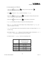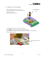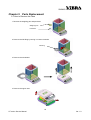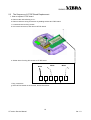
1
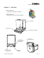
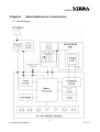
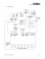
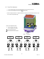
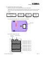
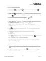
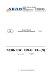
SHINKO DENSHI CO., LTD. Tuning-fork Analytical Balance HTR Series Service Manual (subject to technical modification) Ver. 1.0 HT series Service Manual SHINKO DENSHI CO., LTD. CONTENTS Chapter 1 Total View ・・・・・・・・・・・・・・・・・・・・・・・・・・・・・・・・・・・・・・・・・・・・・・・・・・・・・・・・1 Chapter 2 Electric/Electronic Construction ・・・・・・・・・・・・・・・・・・・・・・・・・・・・・・2 2-1 Block Diagram ・・・・・・・・・・・・・・・・・・・・・・・・・・・・・・・・・・・・・・・・・・・・・・・・・・・・・・・・・・・・・・・2 2-2 Whole Wiring ・・・・・・・・・・・・・・・・・・・・・・・・・・・・・・・・・・・・・・・・・・・・・・・・・・・・・・・・・・・・・・・・3 Chapter 3 3-1 3-2 3-3 3-4 Chapter 4 4-1 4-2 4-3 4-4 4-5 Chapter 5 5-1 5-2 5-3 5-4 Troubleshooting ・・・・・・・・・・・・・・・・・・・・・・・・・・・・・・・・・・・・・・・・・・・・・・・・4 Troubleshooting Procedure ・・・・・・・・・・・・・・・・・・・・・・・・・・・・・・・・・・・・・・・・・・・・・・・・・4 Troubleshooting Table ・・・・・・・・・・・・・・・・・・・・・・・・・・・・・・・・・・・・・・・・・・・・・・・・・・・・・・・5 Primary Check ・・・・・・・・・・・・・・・・・・・・・・・・・・・・・・・・・・・・・・・・・・・・・・・・・・・・・・・・・・・・・・・7 Check of Electric/Electronic Parts ・・・・・・・・・・・・・・・・・・・・・・・・・・・・・・・・・・・・・・・・・・8 Adjustment and Setting ・・・・・・・・・・・・・・・・・・・・・・・・・・・・・・・・・・・・・・10 Span Calibration ・・・・・・・・・・・・・・・・・・・・・・・・・・・・・・・・・・・・・・・・・・・・・・・・・・・・・・・・・・・10 Corner Error Adjustment ・・・・・・・・・・・・・・・・・・・・・・・・・・・・・・・・・・・・・・・・・・・・・・・・・・・12 Address Data Check and Re-setting ・・・・・・・・・・・・・・・・・・・・・・・・・・・・・・・・・・・・・・13 Linearity Adjustment ・・・・・・・・・・・・・・・・・・・・・・・・・・・・・・・・・・・・・・・・・・・・・・・・・・・・・・・15 Adjustment of Over-load Stopper ・・・・・・・・・・・・・・・・・・・・・・・・・・・・・・・・・・・・・・・・・17 Parts Replacement ・・・・・・・・・・・・・・・・・・・・・・・・・・・・・・・・・・・・・・・・・・・・18 How to Remove the Case ・・・・・・・・・・・・・・・・・・・・・・・・・・・・・・・・・・・・・・・・・・・・・・・・・18 Sequence of HT-DP board replacement ・・・・・・・・・・・・・・・・・・・・・・・・・・・・・・・・・・19 Sequence of Mechanical Unit Replacement ・・・・・・・・・・・・・・・・・・・・・・・・・・・・・・21 Sequence of Tuning-fork sensor Replacement ・・・・・・・・・・・・・・・・・・・・・・・・・・・24 Appendix ・・・・・・・・・・・・・・・・・・・・・・・・・・・・・・・・・・・・・・・・・・・・・・・・・・・・・・・・・・・・・・・・・・・・・・・25 The Table of Recommended Minimum Criteria for Adjustment Repair Tool List Ver. 1.0 HT series Service Manual SHINKO DENSHI CO., LTD. Chapter 1 Total View External weight type HT-80(C)E, HT-120(C)E, HT-220(C)E Internal weight type HTR-80(C)E, HTR-120(C)E, HTR-220(C)E Windshield Operation keys LCD display with back-light Connector for peripheral devices (DIN8PIN) RS232C connector (D-SUB 9PIN) Cover for under-weighing hook AC adaptor connector 1 HT series Service Manual Ver. 1.0 SHINKO DENSHI CO., LTD. Chapter2 Electric/Electronic Construction 2-1 Block Diagram 2 HT series Service Manual Ver. 1.0 SHINKO DENSHI CO., LTD. 2-2 Whole Wiring 3 HT series Service Manual Ver. 1.0 SHINKO DENSHI CO., LTD. Chapter 3 Troubleshooting 3-1 Troubleshooting Procedure START Primary Check ( NO "8.8…" lights. AC adaptor is connected NO NO Battery is consumed Connect AC YES YES NO PC board is defective. Check signal waves Display is settled down. NO Connectors are conected NO YES YES Address data changed Display chanes accondring to load YES OK Check address data NO Check stopper NO Connect Plug Adjust the YES NO Check Corner Error Corner Error Adjustment Voltage on PCB is normal NG Replace AC adaptor YES OK NG Address data Resetting Span Adjustment Check NG Linearity HT-10 board is normal Linearity Adjustment YES OK Check signal waves Scale is normal HT-DP board defective Performanc e Check Primary Check Tuning-fork sensor defective Mechanical unit defective Replace tuning fork Replace Mechanical Replace HT-DP NO HT-10 board defective Replace HT-10 4 HT series Service Manual Ver. 1.0 SHINKO DENSHI CO., LTD. 3-2 Troubleshooting Table SYMPTOMS CAUSES & REMEDY No display lights on. 1. 2. 3. 4. 「-」 or 「-」 appears on the display. 1. Wrong weighing pan is applied. 2. Tuning-fork sensor or mechanical unit is defective. 3. HT-DP board is defective. 4. Setting of address data has mistake. 5. Coefficient memories (address data) have changed by noise or static electricity. Re-set the address data and/or adjust the linearity. Display does not get settled down. 1. 2. 3. 4. HT-DP board is defective. AC adaptor is defective. Inner connecting cord is not properly connected. Battery is consumed. Some parts such as stopper touches others. Weighing pan touches other parts. Foreign substances is in the scale. Tuning-fork sensor or mechanical unit is defective. 5. Affected by wind or disturbing oscillation. Display does not repeat correctly. Zero point drifts. 1. Gross weight applied to the scale pan (net weight + tare value) exceeds the scale capacity. 2. Setting of address data has mistake. 3. Coefficient memories (address data) have changed by noise or static electricity. Re-set the address data and/or adjust the linearity. 4. Wrong external weight is used in the span calibration. 「-」appears with net load less than full capacity. Span error is too much. 1. Tuning-fork sensor or mechanical unit is defective. 2. HT-DP board is defective. 5. Setting of address data has mistake. 3. Coefficient memories (address data) have changed by noise or static electricity. Re-set the address data and/or adjust the linearity. Non-linearity is too much. 1. Tuning-fork sensor or mechanical unit is defective. 2. Setting of address data has mistake. 3. Coefficient memories (address data) have changed by noises or static electricity. Re-set the address data and/or adjust the linearity. 4. Wrong external weight is used in span calibration. 5 HT series Service Manual Ver. 1.0 SHINKO DENSHI CO., LTD. SYMPTOMS CAUSES & REMEDY Corner Error is too much. 1. Mechanical unit is defective. Leaf spring is bent or twisted. 2. Pan base touches other parts. Display suddenly disappeared. 1. Battery is being consumed. 2. HT-DP board is defective. 3. AC adaptor is defective. 「-」 or 「-」 appears. 1. HT-DP board is defective. 2. Coefficient memories (address data) have changed by noises or static electricity. Re-set the address data and/or adjust the linearity. 「-」 appears. 1. The weight of reference sample is too light (% mode, counting mode). 「-」 appears. 1. Wrong external weight is used in span calibration (external weight must be more than 50% of the scale capacity). 「-」 appears. 1. Span error exceeds 1% of the scale capacity in span calibration. Check the applied external weight. 「-」 appears. 1. Interval of output is not properly set (see 16-10 in HT user’s manual). 「-」 appears. 1. Internal clock is defective. Check internal clock and replace HT-DP board, if necessary. 「-」 appears. 1. The weight error exceeds ±100.00mg. Re-set the weight error within ±100.00mg (see 14-6 in HT user’s manual). 「-」 appears. 1. Wrong operation in Cumulate Function or Net Addition Function (see 12 in HT user’s manual). 6 HT series Service Manual Ver. 1.0 SHINKO DENSHI CO., LTD. 3-3 Primary Check 1. Is there any wind around the site? Is there any oscillation? 2. Is anything under the pan base or the weighing pan? Pan Pan base 3. Is the weighing pan right one? When you attach or remove pan, pan base, windshield, take care no dust and/or liquid gets into the balance nor under pan/pan base. 4. Is the windshield properly attached? 5. The working table is stable? 6. The balance is installed in level? Position of the air bubble in the level Adjuster 7. AC adaptor is properly connected both with the scale and with outlet? AC adapter connector 7 HT series Service Manual Ver. 1.0 SHINKO DENSHI CO., LTD. 3-4 Check of Electric/Electronic Parts 1. Check of HT-DP board 8 HT series Service Manual Ver. 1.0 SHINKO DENSHI CO., LTD. 2. Check of input voltage TP0 – CN1-1 ・・・・・ + 9V∼ + 14V 3. Power voltage in the circuit TP0 – TP1 ・・・・・ + 4.75V∼ +5.25V TP0 – TP2 ・・・・・ + 3.15V∼ +3.45V TP0 – IC12-O ・・・・・ +7.6V∼ +8.4V TP0 – IC13-OUT ・・・・・ +2.65V∼ +2.95V TP0 – D3 kasode ・・・・・ +2.0V∼ +2.4V TP0- IC8-5 ・・・・・ -8.4V∼ -7.6V 4. Check of signal waves TP0 – IC1-39 (19.968MHz) TP0 – TP4 (38.4MHz) Check of tuning-fork vibration (800∼1000Hz) CH1 : TP0 – TP6 P-P 200mv or more CH2 : TP0 – TP5 P-P 9V or more φ ・・・・・ 70°∼ 100° 9 HT series Service Manual Ver. 1.0 SHINKO DENSHI CO., LTD. Chapter 4 Adjustment and Setting 4-1 Span calibration 1. Calibration with built-in weight (HTR only) a. Push b. Push [ON/OFF] to power ON. 「・・・」, then 「g」 appears. [CAL]. 「 」 appears. c. When 「 」 is displayed, push [CAL] again. d. The built-in weight unit starts to operate, and the balance will automatically start span calibration. e. The display changes in the order of 「 」→「 」→「 」→「」→「」 When span adjustment is completed, the display returns to weighing mode. 2. Calibration with external weight {for HTR, available only with function setting 「 a. Push b. Push . 」 (see user’s manual “5.2 description of function”)} [ON/OFF] to power ON. 「・・・」, then 「g」 appears. [CAL]. 「 」 appears. c. When 「 」 is displayed, push [CAL] again. d. 「 」 appears again, then 「 」starts blinking. Zero point adjustment is automatically performed. e. When 「 」appears, put the external weight around the center of the pan. Display starts blinking to adjust the span automatically. f. 「」→「」 appear in sequence. The span calibration is completed and the balance automatically returns to weighing mode. 10 HT series Service Manual Ver. 1.0 SHINKO DENSHI CO., LTD. 3. Calibration of internal weight (HTR only) a. Set [ ] in function 2 (for function setting, see 14.5 in HT user’s manual ). Push [Function] to display [ ]. b. While pressing 0/T [Zero/Tare] , push [ ] starts blinking and [ [Function] together, and release both keys. ] appears. c. Put the external weight of full capacity on the pan. d. [ ] starts blinking, and the display changes to [ ]. e. Remove the external weight from the pan. f. The display changes [ ]→[ ]→[]. When the calibration is successfully completed, [ ] appears on the display. g. Push [Function] to return to weight display screen. 4. Hints for span calibration a. The span calibration can be performed with external weight of 1/2 of full capacity. Nevertheless, it is recommended to use weight closer to full capacity for accurate calibration. b. Error messages 「」: The external weight is heavier than full capacity. 「」: The external weight is lighter than 1/2 of full capacity. 「」: The data error exceeds 1% of the full capacity. 「」: Any object is put on the pan during calibration procedure. 「」: The weight error exceeds 10% of 「」: The internal drive unit malfunctioned during span calibration. When one of these messages is displayed, calibration will not be performed. c. When you want to stop the calibration, push [SET]. The balance goes back to the weighing mode. 11 HT series Service Manual Ver. 1.0 SHINKO DENSHI CO., LTD. 4-2 Corner Error Adjustment 1. Turn the adjusting legs to bring the bubble of the level to the center of the circle. 2. Put the full scale weight at “A” and Push 0/T [Zero/Tare]. 3. Move the weight to B and C. To adjust bolts R and L referring to the table below so that the corner error is within the specified range. C A 基準点 + B <corner error adjustment table> +: Error is positive to the center −: Error is negative to the center Drive the bolt clockwise Drive the bolt counter-clockwise Bolt L Bolt R Display Display Display Display A A A A C B C B C B C B + − − − − + + + L R L R L R L R 12 HT series Service Manual Ver. 1.0 SHINKO DENSHI CO., LTD. 4-3 Address Data Check and Re-setting a. Why do you need to re-set the address data, and in which case? “Address data” (coefficient memories) sometimes changes by noise in the environment or by static electricity. You can re-set the address data so as to bring back the balance to the initial factory condition. Address data (coefficient memories) changed Re-set Span Primary address data Calibration Check (see 4-1) (see 3-3) You can find the address data sheet on the bottom of the balance. data sheet How to read the address data sheet Number of Tuning fork 音叉番号 Program number プログラム番号 S=81S073 P=AJ0004 3003 00-9A,57,41,98,22,12,9B,32 08-85,19,30,00,27,56,62,80 10-00,18,27,39,26,72,17,12 18-99,72,27,8D,49,27,61,48 20-84,33,77,69,92,20,20,00 28-00,00,20,10,00,00,00,0A 30-06,07,02,0B,07,00,00,FF 38-1C,0B,14,53,0A,00,00,00 40-00,00,00,00,00,00,00,00 48-00,00,5F From left to right 左からAdr.00 ∼: Add. 07 00∼07 From left to right 左からAdr.08 ∼: Add. 0F 08∼0F From left to right 左からAdr.10 ∼: Add. 17 10∼17 From left to right 左からAdr.18 ∼: Add. 1F 18∼1F From left to right 左からAdr.20 ∼: Add. 27 20∼27 From left to right 左からAdr.28 ∼: Add. 2F 28∼2F From left to right 左からAdr.30 ∼: Add. 37 30∼37 左からAdr.38 ∼: Add. 3F 38∼3F From left to right 左からAdr.40 ∼: Add. 47 40∼47 From left to right 左からAdr.48 ∼ 4A 48∼4A From left to right : Add. 13 HT series Service Manual Ver. 1.0 SHINKO DENSHI CO., LTD. b. How to re-set the address data 1. While pressing 0/T [Zero/Tare] and [Function], and turn the power switch ON . You can enter “maintenance mode”. 2. Press and hold and hold [Function]. When「」appears on the display, release the key. Press [Function] again, and when「」appears on the display, release the key. data 3. The first address data (Addr. Number 00) is displayed. 「XX」 Addr. No. 4. Press 0/T [Zero/Tare],「XX. 」appears. Every time 0/T [Zero/Tare] is pressed, the numerical number changes as 「→→・・・→→」. Example : To set 「」at addr. No.「」, select 「」as the first step. 「XX. 」. 5. Press [Function] once, then numerical number (「」in this case) shifts to upper digit. 「XX. 」. 6. Press 0/T [Zero/Tare] again to display a numerical number at the right side. 「XX.」 7. Press 0/T [Zero/Tare] key to select 「」in the right side. By pressing [Function], you set 「」in addr.「」 and move to next address. 8. Input other data by the same procedure. When you set data in all the address, the balance returns to weight display screen. ● Even after you set all data and return to weight display screen, the balance is still in the maintenance mode. In order to exit from the maintenance mode, please turn the power switch OFF. ● If you want to stop address data setting, you push [Set] and return to weight display screen in the maintenance mode. 14 HT series Service Manual Ver. 1.0 SHINKO DENSHI CO., LTD. 4-4 Linearity Adjustment a. Linearity adjustment of HT(R)-80 and HT(R)-120 1. While pressing 0/T [Zero/Tare] and [Function], and turn the power switch ON. You can enter “maintenance mode”. 2. Press [Function] until 「」appears after displaying 「」. 3. While Pressing 0/T [Zero/Tare] first, press [Function] together, and release both. 4. 「 」starts blinking in the display. Zero adjustment is automatically performed. 5. When display changes to 「」blinking, put the external weight according to the table below. (「」∼「」). 6. When 「」appears in the display, press [Function]. The display changes to 「」, and returns to weight display screen. HT(R)-80 HT(R)-120 additional loaded weight additional loaded weight (accumulated load) (accumulated load) 0g (0g) 0g (0g) 20g (20g) 30g (30g) 20g (40g) 30g (60g) 20g (60g) 30g (90g) 20g (80g) 30g (120g) 15 HT series Service Manual Ver. 1.0 SHINKO DENSHI CO., LTD. b. Linearity adjustment of HT(R)-220 1. While pressing 0/T [Zero/Tare] and [Function], and turn the power switch ON. You can enter “maintenance mode”. 2. Press [Function] until 「」appears after displaying 「」. 3. While Pressing 0/T [Zero/Tare] first, press [Function] together, and keep pressing both. When 「」appears in the display, release both keys. 4. While Pressing 0/T [Zero/Tare] first, press [Function] together, and release both. 5. 「 」starts blinking in the display. Zero adjustment is automatically performed. 6. When 「 」appears, put the external weight of 100g. The display changes to「 」, put additional 120g (220g in accumulate). 7. 「 」appears again and remove 120g (100g remains on the pan). The display changes to「 」 and remove 100g. 8. When display changes to 「」blinking, put the external weight according to the table below. (「」 ∼「」). *you don’t need to push [Function] key when “0n5” appears. 9. The display changes to 「」, and returns to weight display screen. HT(R)-220 additional loaded weight (accumulated load) 0g (0g) 50g (50g) 50g (100g) 50g (150g) 50g (200g) 20g (220g) 16 HT series Service Manual Ver. 1.0 SHINKO DENSHI CO., LTD. 4-5 Adjustment of Over-load Stopper 1. Enter “maintenance mode”. (see 4-3 and 4-4). 2. Put “stopper adjustment block” on the mechanical unit Stopper adjustment block referring to the picture. 3. Adjust the level of the balance. 4. Lose stopper fixing screw on the side of mechanical unit. 5. Press 0/T [Zero/Tare] and check whether the indication is stable. 6. Adjust the stopper by sliding the stopper (the stopper should slightly touch with guide-link) 7. Fix the stopper fixing screw Stopper fixing screw 17 HT series Service Manual Ver. 1.0 SHINKO DENSHI CO., LTD. Chapter 5 Parts Replacement 5-1 How to Remove the Case 1. Remove the weighing pan and pan base. Weighing Pan Pan Base 2. Remove the WS Ring by turning it counter-clockwise. WS Ring 3. Remove the windshield. 4. Remove the upper case. 18 HT series Service Manual Ver. 1.0 SHINKO DENSHI CO., LTD. 5-2 The Sequence of HT-DP Board Replacement 1. How to replace HT-DP board a. Remove the case referring to 5-1. b. Remove wires to tuning-fork sensor by welding solders at HT-DP board. c. Loose and remove fixing screws. d. Pull out all connectors, and remove HT-DP board. e. Solder wires of tuning-fork sensor to HT-DP board. White Black G White G G f. Plug connectors. g. Place HT-DP board on the chassis, and fix the screws. 19 HT series Service Manual Ver. 1.0 SHINKO DENSHI CO., LTD. 2. Adjustment after the replacement of HT-DPboard Replacement with new HT-DP board Address data re-setting Linearity Adjustment See 4-3 See 4-4 Calibration of internal weight (HTR only) See 4-1 Span Calibration See 4-1 Performance check 20 HT series Service Manual Ver. 1.0 SHINKO DENSHI CO., LTD. 5-3 The Sequence of Mechanical Unit Replacement 1. How to remove the mechanical unit a. Open the case and remove nylon cramp fixing the connector cables. a b. Pull out RS cable from LF board (power source board). b c. Loose four screws, and remove the sensor cover. c Sensor cover d. Attach “mono-metal fixing block” to the mechanical unit. d Mono-metal fixing block e. Loose two bolts fixing the weight stay, and remove the weight stay. Weight stay e 21 HT series Service Manual Ver. 1.0 SHINKO DENSHI CO., LTD. f. Pull out the connectors and remove HT-DP board. f g. Remove internal weight ASSY first, and then remove span weight. span weight g1 g2 internal weight ASSY h. Loose three screws, and remove the mechanical unit. 22 HT series Service Manual Ver. 1.0 SHINKO DENSHI CO., LTD. 2. How to install the mechanical unit *please refer to the pictures in “How to remove the mechanical unit”. a. Attach the “mono-metal fixing block” to the mechanical unit b. Put the mechanical unit in the chassis (torque:20kgfcm) c. Install the span weight. d. Connect the connector cables to HT-DP board. And attach HT-DP board to the lower case. e. Remove “mono-metal fixing block” form the mechanical unit. f. Install the weight stay. g. Put the sensor cover. h. Connect RS cable to LF board (power source board), and attach the nylon cramp. 3. Adjustment after the replacement with new mechanical unit In case of any defection in the mechanical unit, the mechanical unit should be replaced with new one. After the replacement with new mechanical unit, please make following adjustment and setting. Replacement with new mechanical unit Corner Error Adjustment See 4-2 Linearity Adjustment See 4-4 Calibration of internal weight (HTR only) See 4-1 Span Calibration See 4-1 Adjustment of over-load stopper See Performance check 23 HT series Service Manual Ver. 1.0 SHINKO DENSHI CO., LTD. 5-4 The Sequence of tuning-fork sensor 1. How to replace the tuning-fork sensor 1. Remove the mechanical unit from the chassis (see 5-3). Leave “mono-metal fixing block” attached to the mechanical unit. 2. Loose two bolts and remove the tuning-fork sensor. 3. Install new tuning-fork sensor to the mechanical unit with two bolts (torque: 20kgfcm). 4. Install the mechanical unit to the chassis (see 5-3). 2. Adjustment after the replacement of tuning-fork sensor Replacement with new mechanical unit Corner Error Adjustment See 4-2 Linearity Adjustment See 4-4 Calibration of internal weight (HTR only) See 4-1 Span Calibration See 4-1 Adjustment of over-load stopper See Performance check 24 HT series Service Manual Ver. 1.0 SHINKO DENSHI CO., LTD. Appendix Table of Recommended Minimum Criteria for Adjustment Repeatability *1 Corner Error Non-Linearity *2 HT(R)-80 0.0001g ±0.0005g ±0.0003g HT(R)-120 0.0001g ±0.0005g ±0.0003g HT(R)-220 0.0001g ±0.0005g ±0.0003g *1 standard deviation *2 1/3 of full capacity loaded Repair Tool List 1. Mono-metal fixing block 2. Stopper adjustment block 25 HT series Service Manual Ver. 1.0