1
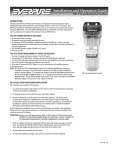
R E S C U E S TA RT S H E R E
OPERATION AND MAINTENANCE MANUAL
FOR
PRT - Percussive Rescue Tool Kit
16 DECEMBER 2011
PN 22-000629
Paratech Incorporated
P.O. Box 1000, Frankfort, IL 60423 USA
Customer Service: 800.435.9358
Phone: 815.469.3911 Fax: 815.469.7748
www.paratech.us E-mail: [email protected]
Paratech Europe, Branch of Paratech Inc.
P.O. Box 174, 5260 Odense S, Denmark
Phone: +45.66.11.24.22 Fax: +45.66.11.24.32
www.paratech.us Email: [email protected]
M A D E
T H E
I N
U S A
LIST OF EFFECTIVE PAGES
Date of original pages is:
Original . . . . . . . . . . . . 1 December 1995
Total number of pages in this publication is 26 consisting of the following:
Page
No.
*Change
No
Title and A...........................................0
Change Record ....................................0
Change Record-2 blank........................0
Foreword-1 ..........................................0
Foreword-2 blank.................................0
i. through iii .........................................0
iv blank ................................................0
* Zero in this column indicates an original page.
Page
No.
*Change
No
1-1 through 1-3.................................... 0
1-4 blank ............................................. 0
2-1 through 2-3.................................... 0
2-4 blank ............................................. 0
3-1....................................................... 0
3-2 blank ............................................. 0
4-1 through 4-3.................................... 0
4-4 blank ............................................. 0
VALIDATION CERTIFICATE
TECHNICAL MANUAL TITLE
OPERATION AND SERVICE MANUAL FOR PRT (PERCUSSIVE RESCUE TOOL)
TECHNICAL MANUAL NUMBER
DATE
P/N 22-000629
16 December 2011
CONTRACT/NO.
I-VALIDATION
Except as stated in II, the technical manual indentified above has been satisfactorily validated in accordance with all
requirements of the applicable contact. The technical manual is hereby certified to be accurate and complete, and the
information, instructions, text, and illustrations conform in all respects to the applicable general and detailed specifications.
II - EXCEPTIONS
EXCEPTIONS
AUTHORIZED BY
NONE
Ken Nielsen
Chief Operating Officer
Paratech Incorporated
1025 Lambrecht Road
Frankfort, Illinois 60423-7000
SIGNATURE OF PUBLICATIONS QUALITY ASSURANCE OFFICER
SIGNATURE ON FILE
QAP20/002/B
DATE
Change Record
Change No.
1
Date
16 DEC 2011
Title or Brief Description
Signature of Validating
Officer
PRT images updated to new style gripping surface
Signature on File
Change Record/(Change Record-2 blank)
FOREWORD
This technical manual conforms to Military Specifications MIL-M-38784, General Style and Format Requirements, MILM-7298 Commercial Equipment Technical Manual and MIL-M-15071 Equipment and Systems Content Requirements for
Technical Manuals. The manual contains description, operating instructions, scheduled maintenance recommendations, and
parts list for the PRT (Percussive Rescue Tool) manufactured by Paratech Incorporated, 1025 Lambrecht Road, Frankfort,
Illinois 60423-1648.
All pertinent data relative to the PRT (Percussive Rescue Tool) is contained herein without specific reference to other
publications. Refer to the table of contents for the arrangement of the contents within this publication.
This manual consists of one volume arranged in four chapters as follows:
Chapter 1 - General Information and Safety Precautions
Chapter 2 - Operation
Chapter 3 - Scheduled Maintenance
Chapter 4 - Parts List
Foreword-1/(Foreword - 2 blank)
TABLE OF CONTENTS
Chapter / Section
Title
Page
1.
GENERAL INFORMATION AND SAFETY PRECAUTIONS
1-1
Safety Precautions...................................................................................................1-1
1-2
Introduction.............................................................................................................1-1
1-3
Equipment Description............................................................................................1-1
1-4
Relationship of Units ..............................................................................................1-3
1-5
Reference Data........................................................................................................1-3
1-6
Equipment, Accessories, and Documents Supplied.................................................1-3
2.
OPERATION
2-1
Introduction.............................................................................................................2-1
2-2
Preparation for Use .................................................................................................2-1
2-3
Controls and Indicators ...........................................................................................2-1
2-4
Applications ............................................................................................................2-1
2-5
Normal Operating Procedure...................................................................................2-1
3.
SCHEDULED MAINTENANCE
3-1
Introduction.............................................................................................................3-1
3-2
Maintnenance Plan..................................................................................................3-1
3-3
General Maintenance ..............................................................................................3-1
4.
PARTS LIST
4-1
Introduction.............................................................................................................4-1
4-2
List of Major Components ......................................................................................4-1
4-3
Parts List Tables......................................................................................................4-1
4-4
List of Manufacturers..............................................................................................4-1
LIST OF ILLUSTRATIONS
Figure
1-1
1-2
1-3
1-4
1-5
1-6
1-7
1-8
1-9
1-10
2-1
2-2
4-1
4-2
Title
Page
The PRT..................................................................................................................1-1
Bull Point - 14” Long..............................................................................................1-1
3” Wide Chisel - 14” long .......................................................................................1-1
1” Wide Chisel - 14” long .......................................................................................1-1
Lock Breaker Claw .................................................................................................1-2
Metal Cutting Claw.................................................................................................1-2
6” Penetrator Applicator .........................................................................................1-2
14” Penetrator Applicator........................................................................................1-2
Quick Connector .....................................................................................................1-2
PRT Kit Carrying Pouch .........................................................................................1-2
Operation of Controls..............................................................................................2-1
PRT Lock/Unlock Label .........................................................................................2-2
PRT Assembly Parts List ........................................................................................4-2
PRT Tool Bits and Accessories Parts List ...............................................................4-3
i
LIST OF TABLES
Number
1-1
1-2
3-1
4-1
4-2
4-3
ii
Title
Page
Reference Data........................................................................................................1-3
Reference Data - Overall Length and Total Weigth; PRT with Accessories............1-3
Maintenance Schedule.............................................................................................3-1
PRT Assembly Parts List ........................................................................................4-2
PRT Tool Bits and Accessories Parts List ...............................................................4-3
Manufacturer’s List .................................................................................................4-3
SAFETY SUMMARY
The following are general safety precautions. These are
recommended precautions that personnel must understand
and apply during many phases of operation and
maintenance.
WARNING
Keep the work area clean when maintaining or repairing
the PRT.
Personnel not directly involved in operation
or
maintenance of the PRT should keep a safe distance from
the work area.
Operation of the PRT by unauthorized personnel or
minors is prohibited.
Use the proper tool bit for each application.
Wear proper apparel: Safety Goggles, Hard Hat, Gloves,
and Safety Shoes.
When changing or installing tool bits, always make
certain the tool retainer locking ring is securely locked in
place before ramming the handle. If it is not sufficiently
locked in place the tool bit will fly out of the end of the
PRT and could present a serious hazard.
WARNING
Use a respirator in contaminated environments.
During operation, do not over reach. Keep stable footing
and balance at all times.
Don’t pry with the PRT when attached to either the 6” or
14” penetrator. Such action can break the penetrator.
The following warnings and cautions appear in the text of
this manual, and are repeated here for emphasis:
WARNING
Always make sure that the handle and ram of the PRT are
locked by the collet ring before changing tool bits. If the
handle and ram are not locked down, they will succumb to
gravity as the PRT is turned over and could cause injury.
Locking the ram and handle in an open position is not
considered a positive lock. The ram and handle can still be
moved if a sufficient force is acting upon them. The
strength of the lock in an open position is dependent upon
the hand strength of the operator.
CAUTION
Keep fingers clear of the bottom of the handle and collet
ring when ramming.
CAUTION
Keep hands and other body parts away from the end of the
tool bit when ramming.
iii
CHAPTER 1
GENERAL INFORMATION AND SAFETY PRECAUTIONS
1-1 SAFETY PRECAUTIONS
Refer to the Safety Summary preceding Chapter 1,
“General Information and Safety Precautions”, for safety
precautions necessary for the protection of personnel and
equipment.
1-2 INTRODUCTION
This technical manual provides instructions for the
operation, maintenance, and parts support for the PRT
(Percussive Rescue Tool) manufactured by Paratech
Incorporated, 1025 Lambrecht Road, Frankfort, Illinois
60423-1648.
light weight and steel (ram) for strength. It features a
machine grooved non-slip handle, a collet ring that can
lock the ram in any position to aid in leverage, and a tool
retainer with its own locking ring that allows for quick
and safe tool bit changes.
1-3.2 PRT TOOL BITS AND ACCESSORIES
Unlike other single task tools, the PRT allows the operator
to select from a wide range of tool and penetrator bits that
best suit to the job at hand. The PRTtool bits are
manufactured from forged heat treated alloy steel to
provide high impact strength and long tool life.
a. Bull Point - 14” The Bull Point tool bit is ideal
for breaking concrete and masonry materials.
The PRT is designed for use in rescue situations involving
forcible entry and penetration.
The PRT is manufactured from aluminum (housing) for
light weight and steel (ram) for strength. The PRTtool
bits are manufactured from forged heat treated alloy steel
to provide high impact strength and long tool life.
1-3 EQUIPMENT DESCRIPTION
1-3.1 PRT (PERCUSSIVE RESCUE TOOL)
The PRT is a powerful, manually operated forcible entry
and penetration tool. The PRT uses the “Slam and Ram”
principle of operation to maximize its power and to retain
the efficiency of one man operation. Because there is no
deflection of the pounding force, all of the energy is used
to strike effective, penetrating blows by a single person.
Figure 1-2. Bull Point - 14” Long
Part No. 22-098101
b. 3” Wide Chisel - 14” The 3” Wide Chisel is
used for prying, metal cutting, and its extra long
length is perfect for reaching into areas that are extra
deep and narrow.
Figure 1-3. 3” Wide Chisel - 14” Long
Part No. 22-098107
c. 1” Wide Chisel - 14” The 1” Wide Chisel is
good for prying, breaking bolts, and breaching brick
and block walls.
Figure 1-1. The PRT (Percussive Rescue Tool)
Part No. 22-000627
When hydraulic, electric, and pneumatic power is
unavailable, the PRT allows you to continue working your
way through various materials such as wood, block,
concrete, metal, or composites.
The PRT is manufactured from aluminum (housing) for
Figure 1-4. 1" Wide Chisel - 14" Long
Part No. 22-098111
1-1
d. Lock Breaker Claw The Lock Breaker Claw is
used for prying and forcing open roll-up doors, elevator door, fire doors, windows, twisting open hasps
and locks, and pulling large nails or spikes.
*h. Quick Connector The Quick Connector coupling is made from hard coated aluminum alloy and is
used to hook up the PRT/Penetrating Applicator to
whatever extinguishing media you happen to be
using. Two Quick Connector coupling models are
available, depending upon the connection necessary,
NH or NPSH.
Figure 1-5. Lock Breaker Claw
Part No. 22-000636
e. Metal Cutting Claw The Metal Cutting Claw is
made to cut the metal of automobiles, aircraft, metal
structures such as corrugated sheds, etc.
Figure 1-6. Metal Cutting Claw
Part No. 22-000637
Figure 1-9. Quick Connector
Part No. 22-550320 or 22-550330
i. PRTKit Carrying Pouch The PRT Kit Carrying
Pouch is made from tough, strong vinyl coated nylon
and features velcro straps for easy access and worryfree storage. It stores all the standard items that
come with the PRT Kit, rolls up easily, and has two
handy carrying straps so you can take the PRTjust
about anywhere.
*f. 6” Penetrator Applicator The 6” Penetrator
Applicator is made from heat treated alloy steel and
is used as a penetrating nozzle that will flow water,
AFFF/foam solutions, halon, and carbon dioxide.
The penetrator applicator was designed to allow
access to battery/engine housings, aircraft fuselage,
and watertight compartments. The 6” Penetrator
Applicator has a capacity of 65 GPM @ 100 PSI
(345 LPM @ 6.8 bar).
Figure 1-7. 6” Penetrator Applicator
Part No. 22-098106
*g. 14” Penetrator Applicator The 14” Penetrator
Applicator is also made from heat treated alloy steel
and has a capacity of 115 GPM @ 100 PSI (436
LPM @ 6.8 bar).
Figure 1-10. PRT Kit Carrying Pouch
Part No. 22-015472
(*Optional Tools and accessories for use with the
PRT)
1-4 RELATIONSHIP OF UNITS
Figure 1-8. 14” Penetrator Applicator
Part No. 22-098114
1-2
Refer to Figures 1-1 through 1-10 for pictorial illustrations
of the PRT and its tool bits and accessories.
1-5 REFERENCE DATA
Reference data pertaining to the PRT and its accessories
are summarized for quick reference in tables 1-1 and 1-2
Table 1-1. Reference Data
PRT (PERCUSSIVE RESCUE TOOL) without tool bit
26.6" - 39.3" (67.6 cm - 99.8 cm)
Part Number ....................................... 22-000627
Stroke ..........................................12.7" (32.3 cm)
Net Weight .................................. 10.0 lb (4.5 kg)
BULL POINT
18" long (45.7 cm)
Part Number ....................................... 22-098101
Net Weight .................................... 3.3 lb (1.5 kg)
3” WIDE CHISEL
18" long (45.7 cm)
Part Number ....................................... 22-098107
Net Weight .................................... 3.9 lb (1.8 kg)
1” WIDE CHISEL
18” long (45.7 cm)
Part Number ....................................... 22-098111
Net Weight .................................... 3.3 lb (1.5 kg)
LOCK BREAKER CLAW
12.5" long (31.8 cm)
Part Number ....................................... 22-000636
Net Weight .................................... 3.6 lb (1.6 kg)
METAL CUTTING CLAW
12.3" long (31.2 cm)
Part Number ....................................... 22-000637
Net Weight .................................... 3.0 lb (1.4 kg)
6” PENETRATOR APPLICATOR
17.7" long (45.0 cm)
Part Number ....................................... 22-098106
Net Weight .................................... 3.0 lb (1.4 kg)
4” PENETRATOR APPLICATOR
26.9" long (68.3 cm)
Part Number ....................................... 22-098114
Net Weight .................................... 3.8 lb (1.7 kg)
QUICK CONNECT COUPLING
Table 1-2. Reference Data - Overall Length and Total
Weight; PRT with Accessories
PRT Kit Complete
Total Length ............................... 27.4” (69.6 cm)
Total Weight.............................. 29.2 lb (13.2 kg)
PRT with BULLPOINT
Total Length ......40.3” - 53.0” (102.4 - 134.6 cm)
Total Weight................................ 14.5 lb (6.6 kg)
PRT with 3” WIDE CHISEL
Total Length ......40.3” - 53.0” (102.4 - 134.6 cm)
Total Weight................................ 15.1 lb (6.8 kg)
PRT with 1” WIDE CHISEL
Total Length ......40.3” - 53.0” (102.4 - 134.6 cm)
Total Weight................................ 14.5 lb (6.6 kg)
PRT with LOCK BREAKER CLAW
Total Length ........34.8” - 47.5” (88.4 - 120.7 cm)
Total Weight................................ 14.8 lb (6.7 kg)
PRT with METAL CUTTING CLAW
Total Length ........34.6” - 47.3” (87.9 - 120.1 cm)
Total Weight................................ 14.2 lb (6.4 kg)
PRT with 6” PENETRATOR APPLICATOR
Total Length ......40.0” - 52.7” (101.6 - 133.9 cm)
Total Weight................................ 14.2 lb (6.4 kg)
PRT with 14” PENETRATOR APPLICATOR
Total Length ......49.2” - 61.9” (125.0 - 157.2 cm)
Total Weight................................ 15.0 lb (6.8 kg)
1-6 DOCUMENTS SUPPLIED.
No documents other than this publication are required as
supporting literature for the PRT (Percussive Rescue
Tool).
1 1/2" NH - Connection
Part Number ....................................... 22-550320
Net Weight .................................... 0.5 lb (0.2 kg)
1 1/2" NPSH - Connection
Part Number ....................................... 22-550330
Net Weight .................................... 0.5 lb (0.2 kg)
CARRYING POUCH
Part Number ....................................... 22-015472
Net Weight .................................... 1.4 lb (0.6 kg)
1-3/(1-4 blank)
CHAPTER 2
OPERATION
2-1 INTRODUCTION
The PRT is designed for use in rescue situations involving
forcible entry and penetration.
The specific situation requiring the use of the PRT will
generally determine which tool bit or optional accessory
will be required to be utilized in combination with each
other.
2-2 PREPARATION FOR USE
2-2.1 PRT
Before using the PRT, all operators should read the
SAFETY SUMMARY preceding Chapter 1 of this manual
and become familiar with all the warnings and cautions
contained throughout this manual.
Only personnel trained and qualified in rescue should be
allowed to operate the PRT.
Personnel not directly involved in operation of the PRT
should keep a safe distance from the work area.
PRT operators should be wearing the proper safety apparel
indicated in the SAFETYSUMMARY preceding Chapter
1.
Always make sure that the handle and ram of the PRT are
locked by the collet ring before changing tool bits. If the
handle and ram are not locked down, they will succumb to
gravity as the PRT is turned over and could cause injury.
When changing or installing tool bits, always make certain
the tool retainer locking ring is securely locked in place
before ramming the handle. If it is not sufficiently locked
in place the tool bit will fly out of the end of the PRT and
could present a serious hazard.
Keep fingers clear of the bottom of the handle and collet
ring when ramming.
Keep hands and other body parts away from the end of the
tool bit when ramming.
2-3 CONTROLS AND INDICATORS
2-3.1 CONTROLS
The controls of the PRT consist of the following:
the Tool Retainer Locking Ring and the Collet Ring.
See Figure 2-1. Operation of Controls.
a. Tool Retainer Locking Ring - The Tool Retainer
Locking Ring is used during the installation or changing of tool bits. With the PRT held in a vertical position with the ram and handle end at the bottom and
the tool retainer end at the top, the tool retainer
locking ring is rotated clockwise to disengage the
tool retainer finger that holds the tool bit in place.
When the tool retainer locking ring is tightened
counter-clockwise, the finger comes into contact with
it and is prevented from opening any further, thus
keeping the tool bit from emerging from the tool
retainer when the ram is struck.
b. Collet Ring - The Collet Ring is primarily used to
lock the ram and handle in the closed position for
safety while carrying the PRT. It also has the capability of locking the handle and ram in an open position anywhere along the length of the stroke.
COLLET RING
RETAINER FINGER
TOOL BIT
SHANK
TOOL RETAINER
LOCKING RING
LOCK
UNLOCK
LOCK
HANDLE & RAM
UNLOCK
Figure 2-1. Operation of Controls
2-1
for breaking concrete and masonry materials.
WARNING
It should be noted, however, that locking the ram and
handle in an open position is not considered a positive
lock. The ram and handle can still be moved if a sufficient force is acting upon them. The strength of the
lock in an open position is dependent upon the hand
strength of the operator.
Holding the PRT in a vertical position with the tool
retainer end at the bottom and the ram and handle end
at the top, the Collet Ring is rotated counter-clockwise to disengage the collet chuck that grips the ram
and allows the ram and handle to slide freely inside
the PRThousing. Tightening the Collet Ring by
Rotating it clockwise clamps down on the collet
chuck, thus inhibiting the ram and handle’s freedom
of movement.
2-3.2 INDICATORS
The indicators on the PRT consist of the following:
Labels on Tool Retainer and the Housing.
a. Tool Retainer Label - An easy to understand
graphical representation of the two possible states
of the tool retainer. By rotating the tool retainer locking ring in the directions indicated on the label, it becomes either locked or unlocked.
b. Collet Ring Label - Identical to the tool retainer
locking ring label, it is an easy to understand graphical representation of the two possible states of the collet ring. By rotating the collet ring in the directions
indicated on the label, it becomes either locked or unlocked.
b. 3” Wide Chisel - 14” The 3” Wide Chisel is
used for prying, metal cutting, and its extra long
length is perfect for reaching into areas that are extra
deep and narrow.
c. 1” Wide Chisel - 14” The 1” Wide Chisel is
good for prying, breaking bolts, and breaching brick
and block walls.
d. Lock Breaker Claw The Lock Breaker Claw is
used for prying and forcing open roll-up doors, elevator doors, fire doors, windows, and twisting open
hasps and locks.
e. Metal Cutting Claw The Metal Cutting Claw is
made to cut the metal of automobiles, aircraft, metal
structures such as corrugated sheds, etc.
*f. 6” Penetrator Applicator The 6” Penetrator
is used as a penetrating nozzle that will flow water
AFFF/foam solutions, halon, and carbon dioxide.
The penetrator applicator was designed to allow
access to battery/engine housings, and watertight
compartments. The 6” Penetrator Applicator has a
capacity of 65 GPM @ 100 PSI (345 LPM @ 6.8
bar).
*g. 14” Penetrator Applicator The 14” Penetrator
Applicator has a capacity of 115 GPM @ 100 PSI
(436 LPM @ 6.8 bar).
*h. Quick Connector The Quick Connector coupling is used to hook up the PRT/Penetrating Applicator to whatever extinguishing media you happen
to be using. Two Quick Connector coupling models
are available, depending upon the connection necessary, NH or NPSH.
2-5 NORMAL OPERATING PROCEDURES
UNLOCKED
Figure 2-2.
PRT Lock/Unlock Label
LOCKED
2-4 APPLICATIONS
The PRT is a forcible entry and penetrating tool, so its
application parameters are defined by the materials it will
be working on. The choice of the proper tool bit for
varying materials is the most important factor to consider
when using the PRT. The following descriptions should
help you in determining the proper tool bit for the job at
hand.
a. Bull Point - 14” The Bull Point tool bit is ideal
2-2
Operation of the PRT is fairly simple, just follow these
steps:
1. Unroll the PRTcarrying pouch.
2. Select the tool bit best suited for the task at hand.
(Reference Figure 2-1 Operation of Controls, page 2-1)
3. Make certain that the ram and handle are in a locked
position so they won’t slide out of the housing
unexpectedly while you are installing the tool bit.
Accomplish this by twisting the collet ring in the direction
indicating “Locked” on the collet ring label located on the
PRT housing near the handle.
4. Insert the shank end of the tool bit into the tool
retainer. If the tool retainer finger impedes the tool bit
from seating completely into the retainer, release the tool
retainer more by twisting the tool retainer ring in the
direction indicating “Unlocked” on the tool retainer label
until the collar on the tool bit clears the tool retainer
finger.
5. Lock in the tool bit by rotating the tool retainer ring in
the direction indicating “Locked” on the tool retainer
label. This will close the tool retainer finger over the
shank of the tool bit and hold it in place.
6. Now that the tool bit is securely in place, place the
working tip of the tool bit on the work surface where you
want to begin penetrating.
7. Release the ram and handle of the PRT by rotating the
collet ring in the direction indicating “Unlocked” on the
collet ring label located on the housing near the handle
until the ram and handle operate smoothly when
withdrawn and repeatedly struck (Slam and Ram) against
the tool bit.
WARNING
ALWAYS CHECK TO MAKE SURE THAT THE COLLET RING
IS IN THE LOCKED POSITION WHEN THE PRT IS NOT IN
SERVICE TO PREVENT THE RAM AND HANDLE FROM
ACCIDENTLY SLIPPING OUT OF THE HOUSING AND
INJURING ANYONE.
WARNING
ALWAYS OPERATE THE PRT AGAINST A WORK SURFACE.
WARNING
ALWAYS KEEP THE TOOL BITS SHARP AND WELL EDGED.
NOTE: If using the optional 6” or 14” Penetrators in
conjunction with PRT, it is always the best practice to
penetrate the material first before attaching any fire hoses
or other extinguishing medium to the penetrator. Also, if
you need to penetrate through concrete or masonry and are
planning to use the optional penetrators, use the bull point
tool bit to penetrate the concrete or masonry first. then
switch to the penetrators to extinguish.
2-3/(2-4 blank)
CHAPTER 3
SCHEDULED MAINTENACE
3-1 INTRODUCTION
The major components of the PRT and its accessories
require little maintenance to ensure optimum performance.
This chapter provides preventative maintenance
procedures.
3-2 MAINTENANCE PLAN
Preventative maintenance for the PRT is accomplished in
accordance with the PRT Maintenance Schedule in Table
3-1.
3-3 GENERAL MAINTENANCE
3-3.1 GENERAL
General maintenance shall be performed as detailed in the
PRT Maintenance Schedule in Table 3-1.
3-3.2 SURFACE CLEANING
As with any quality tool, the state of cleanliness of it can
affect its performance and lifespan. Following the
procedures in the PRT Maintenance Schedule in Table 3-1
will assist you in keeping your PRT clean and effective.
3-3.3 INSPECTION
Operators should inspect the PRT and its tool bits and
accessories before and after each use to ensure safe,
effective, and efficient use. If corrective action is
necessary, follow the procedures outlined in the PRT
Maintenance Schedule in Table 3-1.
3-3.4 TOOL BIT SHARPENING
Combine the scheduling outlined in Table 3-1 and the
following instructions to keep your tool bits sharp and
productive.
a. 1” & 3” Chisels - Using a grinding wheel or file,
grind down cutting edge to approximately 45 degrees
on each side to produce a sharp, even cutting edge.
b. Bull Point - Using a grinding wheel or file,
grind down all four sides of point to approximately
45 degrees to produce a sharp, even penetrating point.
c. Metal Cutting Claw - Using a grinding wheel or
file, grind down both sides of the chisel portion of
the claw to approximately 45 degrees to produce
a sharp, even cutting edge. On the claw portion, use
a belt-sander along the back (flat) side cutting edge
to clean up any nicks, notches, or other irregularities.
d. Lock Breaker Claw - Using a grinding wheel or
file, grind down 1” of the rounded side of the claw
at the tips of the forks being careful to keep their
thickness and length as close to equal as possible.
3-3.5 STORAGE
The PRT, its tool bits, and accessories should be stored in
a dry, flat area.
Table 3-1 Maintenance Schedule
Frequency
Maintenanc
e Requirement
Paragraph
During Use
Keep Tool Bit Sharp
3-3.4
After Use
Keep Tool Bit Sharp, Clean Ram ( Clean of all debris,
wipe down with a rag lightly oiled with a lubricant such
as WD40), Clean grooves on Handle and Housing to
provide a good grip, Make sure all fasteners (screws, etc.)
tightened.
3-3.1, 3-3.2
Lubricate threads on Tool Retainer Locking Ring
and Collet Ring with WD40 type lubricant to ensure
3.32
are
Quarterly
3-1/(3-2 blank)
CHAPTER 4
PARTS LIST
4-1 INTRODUCTION
This chapter list standard and optional parts for the PRT
(Percussive Rescue Tool). The parts list is used to
identify and locate all repair parts, including all attaching
hardware supplied. The parts should be ordered by part
number when ordered from Paratech Incorporated, 1025
Lambrecht Road, Frankfort, Illinois 60423-1648.
4-2 LIST OF MAJOR COMPONENTS
The PRT is comprised essentially of detail parts and
contain no major components.
4-3 PARTS LIST TABLES
The PRT’s parts and accesories are listed in Table 4-1
through 4-2. The table(s) contain five columns which are
described below.
4-3.1 FIGURE AND INDEX NUMBER COLUMN
This column shows the figure and index number of each
part listed. Tables 4-1 through 4-2 relate to illustrations
contained in chapter 4. The index numbers which identify
the individual parts are separated from the figure number
by a hyphen. Index numbers run consecutively.
4-3.2 DESCRIPTION COLUMN
The DESCRIPTION column describes each part (by noun
names and modifiers) in sufficient detail for clarity.
Descriptions are successively indented to the right to show
assembly and part relationship.
4-3.3 QUANTITY COLUMN
Quantities specified in the QUANTITY column are the
total number of each part required per assembly.
4-3.4 CAGE COLUMN
The assembly and parts are identified by a five digit code.
These code numbers are in accordance with Federal
Supply Cataloging Handbook H-4-1. A cross reference
between these codes and the manufacturer’s is shown in
Table 4-3.
4-3.5 PART NUMBER COLUMN
The part number column contains an identifying number
for each part listed. Vendor numbers are shown where
applicable.
4-4 LIST OF MANUFACTURERS
A list of all manufacturers’ code numbers used in the parts
list is shown in Table 4-3. These codes are in accordance
with Federal Supply Cataloging Handbook H-4-1.
4-1
13
12
1
2
14
11
3
10
4
5
8
6
7
9
Figure 4-1. PRT Components
Table 4-1. PRT Assembly Parts List
Figure
and
Index
Number
4-1
-1
-2
-3
-4
-5
-6
-7
-8
-9
-10
-11
-12
-13
-14
4-2
Description
Quantity
PRT ASSEMBLY..................................................
HANDLE & RAM ASSEMBLY.......................
Handle.............................................................
Rubber Bumper...............................................
Grooved Pin....................................................
Ram..................................................................
Collet Ring......................................................
Collet Chuck...................................................
O-Ring............................................................
Sleeve..............................................................
Grooved Pin....................................................
HOUSING ASSEMBLY....................................
Housing Tube..................................................
Tool Bit Retainer.............................................
Retainer Finger................................................
Retainer Locking Ring....................................
Screw...............................................................
NOT SHOWN
Labels
1
1
1
1
1
1
1
1
1
1
1
1
1
1
1
1
1
CAGE
Part
Number
30978
30978
30978
30978
30978
30978
30978
30978
30978
30978
30978
30978
30978
30978
30978
30978
30978
22-000627
22-015720
22-015721
22-015726
22-015049
22-015722
22-015725
22-015724
22-895248
22-015723
22-015015
22-015710
22-015711
22-015712
22-015713
22-015714
22-015715
1
2
3
5
4
8
6
7
9
Figure 4-2. PRT Tool Bits and Accessories
Table 4-2. PRT Tool Bits and Accessories Parts List
Figure
and
Index
Number
4-2
-1
-2
-3
-4
-5
-6
-7
-8
-9
Description
Quantity
PRT TOOL BITS & ACCESSORIES..................
Bull Point - 14” long.......................................
3” Wide Chisel - 14” long...............................
1” Wide Chisel - 14” long...............................
Lock Breaker Claw..........................................
Metal Cutting Claw.........................................
6” Penetrator Applicator (optional).................
14” Penetrator Applicator (optional)...............
Quick Connector Coupling NH (optional).....
Quick Connector Coupling NPSH (optional)
PRT Kit Carrying Pouch.................................
1
1
1
1
1
1
1
1
1
1
CAGE
Part
Number
30978
30978
30978
30978
30978
30978
30978
30978
30978
30978
22-098101
22-098107
22-098111
22-000636
22-000637
22-098106
22-098114
22-550320
22-550330
22-015472
Table 4-3. Code to Name List
CAGE
Manufacturer’s or Vendors Name and Address
30978
Paratech Incorporated, 1025 Lambrecht Road, Frankfort, Illinois 60423-1648
4-3/(4-4 blank)