1
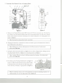
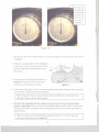
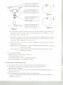
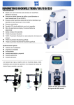
IIIIIC®
Industrial Supply
USER MANUAl
FOR
ROCKWEll HARDNESS TESTER
Thanks for Purchasing Rockwell Hardness Tester
Please read this Manual carefullv before vour operating
If vour Hardness Tester do not work properlv
please check relative contents
If problem still exists, please contact vour dealer for further help
User Manual
for
Rockwell Hardness Tester Model HR-150A (mhc# 639-2030)
Following these instructions to operate your Hardness Tester correctly and quickly.
This User Manual shows the steps for preparing, operating and maintaining, Kindly please check detail carefully
and any further help please contact your dealer.
B. Loosening all fastening screws at the
bottom of machine.
C. Installing the Tester in a suitable room,
the bench for Tester must be rigid and
a bore with diameter over 2 inch for
decending of Working Plate.
D.Openning the Top Cover and Back
Cover (Part#6, 19) as GREEN parts
marked in Figture 1.
E. Removing all parts marked YELLOW in
Figture 1, parts name and list as below:
I.Part#3, Penetrator Pad.
2.Part#4, Fastening Rope.
3. Part#7 & 11, Plastic Upper & Lower Covers.
4. l.Part#8&9, two Crooked Studs and Nuts.
5. Part#12,13&14, two Crooked Studs, Nuts and one Plastic Fixing Plate.
6.Part#18, Plastic Weight Support Block.
G. Removing the Protective Cover(Part#30 in Figture 2), cleanning away the antirust oil on the Thread
Spindle with kerosene, then filling some lubricant and put on the cover for Thread Spindle again.
H. Cleanning the Working Plate (Part#25, choosing one from three according testing part) packed in
accessories case and then putting it on the top of Thread Spindle (Part#30 in Figture 2). Adjusting the
horizontality of Hardness Tester within 0.2/1000 via precison level placed on the working plate.
1. Checking the Adjusting Block(Part#6
reassembling
in Figture 2) if it locates between two red marks. If not,
it to right position. Then, put back the Top Cover and Back Cover for next step.
--..--14
011 let
7
A. Taking out one Standard Block marked HRC between 40-50 from Accessories case. The block has
two surfaces, one side marked hardness data which is measuring surface, the other one is bottom
surface which cannot be measured. Cleanning its two surfaces and place it on working plate as test
sample in Figture 2.
B. Changing the Penetrator to Diamond one. Please be careful to get out ofPenetrator from Tester in
case of falling down and destroy it.
Note: Making sure to choose right penetrator for different material. Further detail,
please check Table One.
C. Turning the Test Force Knob (Part#13 in Figture 3) to test force 15Okgfposition. Making sure that
Unloading Handle (Part# 16 in Figture 4) in unloading position as Figture 4.
Note: Loading different test force for different materials or hardness. For further detail,
please check Table One.
D. Swivelling up the Working Plate(Part#27 in Figture 4)
slowly to support up the penetrator till the Small Finger
of indicator points at the red mark, the Big Finger turns 3
circles and stop vertically as right picture of Figture 5.
Note: It is allowed to have a err<;>rof ±5 graduations no matter in unloading situation or in
loading situation. If over this range, please check Article 4.C.
Rotating
this
dial shell and
Set Big Finger
same line with
l
E. Rotating
the outer shell of Dial Indicator
to get the Big Finger
in same line with C-B as shown
in Figture 5.
F. Pulling the Loading Handle(Part#
15 in Figture 6)
to apply main test force as arrow direction, at this
moment the Big Finger of Dial Indicator rotates
anticlockwise.
G. Pushing back the Unloading Handle(Part#16
in
Figture 6) to release the main test force after
the Big Finger of Indicator stops clearly.
H. Waiting for the Big Finger fixed on one data and getting the black data of Hardness Tester from Dial
at the situation of testing with Diamond Penetrator.
Note: Getting the C data from dial if testing with Diamond Penetrator, Getting the B data
from dial if testing with Steel Ball Penetrator.
I. If it is first time using either for this machine or for penetrator, We must repeat procedure
from E to I three times. That is to loosen the Working Plate and then pull the block to another area,
then take steps as above. After three times, the testing data should be same with the data marked on
Standard Blocks.
Note: The tolerance for this Standard Block should be within ±I .2. If over the range after
three times testing, please check Article 4.C.
3. Operating Procedure for Actual Testing
A. Choosing suitable penetrator according to actual testing part.
B. Placing the testing part on working plate as 2.A
C. Repeat the Procedure
from 2.C to 2.1
D. Get the data as Procedure 2.T.
A. There are two penetrators
in our accessories,
choose the corresponding
penetrator
normally steel ball penetrator installed in Tester. We need to
according to testing parts material or approximate
hardness shown as
Table One. Also, choose the right test force correctly according to different hardness range.
If NOT, will
destroy the Penetrator. Detail as Table One.
Two Ways to Choose Penetrator
Penetrator
Steel Parts
HRB 20-100
HRC 20-70
Hardness over HRC70 such as
Tungsten, Carbide Alloy etc.
the meantime,
Steel
Ball Penetrator
Penetrator
1200 Diamond
HRA 20-88
B. Using First time for the new machine
the procedure
<p 1/16'
1200 Diamond
Heat treated Steel Parts
preform
Force
(kgf)
Measuring
Tolerance
Range
Softer, Middle Hardness or
Unquenched
Needed
Part Hardness
Testing Materials
Test
or operating
Penetrator
±1.5
100
±1.5
Low:
150
Middle: ±1.2
High: ±1.0
±1.0
60
first time after changing
three times in order to impact all parts to right position
the penetrator,
MUST
and get right data. At
need to screw up locking screw for the penetrator.
C. Normally we NEED NOT adjust the inside structure of Tester, but, because of shipping shock or human
factor, measuring result out of tolerance happens sometimes.
That will request us to adjust the screws on
Small Level ( See Figture 7) in order to get the right readout from Dial Indicator.
Openning
Top Cover as shown in Figture 1, and you will find the Part#5 in Figture 1, the planform
of Small Level as shown in Figture 7. Then, adjust the screws on small level according
instruction.
to follow
Screws#I&2 to adjust left or
right position of small level.
Screws#3&4 to adjust the
position of small metal sheet
Locking Nut & Screw#5 to
adjust the big finger to
vertical position
The Pin end of Small Level
insert into hole of indicator
1). If the big finger of indicator do not point vertically and out of tolerance( error tolerance is ±5
graduations), just loosening the Locking Nut#5 adjusting the Screw in Figture
position(B-C),
7 to vertical
then relocking the Nut.
2). If the Pin End of Small Level do not locate in the middle of hole of as Figture 8, just loosening the
Screw# 1&2 in Figture
7 and moving the Small Level right or left to make the Pin End of Level
in the middle of hole as Figture 9, then screwing it down.
3).If measuring result is out of tolerance as shown in Table One, loosening the Screws#3&4 and
adjusting them as below:
If Measuring Result ) Standard Data, moving the Small Metal Sheet backward relative to indicator,
till making two data equal.
If Measuring Result < Standard Data, moving the Small Metal Sheet forward relative to indicator,
till making two data equal.
D. Main Accessories included:
Working Plate(Large, Small, V-Shape), 1 Piece each
1205Diamond Penetrator: 1 Piece
1/161Steel Ball Penetrator: 1 Piece (Normally install in Tester)
Rockwell Standard Blocks: 5 Pieces (Different Hardness)
A. If the Tester do not be in use for a long time, it should be covered with dustproof cover.
B. Fill machine oil periodically on the contacting surface of the Screw(Part#26) and the
Handwheel(Part#27 in Figture 2).
C. Before use of the Tester, make clean the top surface of the Screw(Part#26 in Figture 2) and the up
end surface of the anvil.
D. If the Tester measuring result has bigger deviation, please check below:
1). Remove the working plate(Part#27) and check if its surface contacted with the Screw(Part#26 in
Figture 2) is clean or not
2). Check if the protective jacket supports up the anvil or not
3). Check if the Penetrator is damaged or not
E. When applying the main test force, the indicator finger rotates very fast at the beginning and then slowly,
it means that the machine oil in the Buffer is too less. In this case, lift up the cover on the top of
Buffer (Part#7 in Figture 2), fill in machine oil and meanwhile push and pull the Handles
(Part#15, 16 in Figture 2) many times to get the Buffer filled fully.
F. Use the standard test blocks to check periodically the accuracy of the Hardness Tester.
1). Clean the anvil and the standard block, and then carry one the test with the working surface of the block,
It is FORBIDDEN to test with its supporting surface of the standard block.
2). If the deviation is very big, besides checking this article E, check if the supporting surface is iwht burrs
or not. If Yes, polish this surface with oil stone.
3). If the testing on a standard block in different positions, the block should be pulled on the working plate
of Anvil and not taken off from it.
A. Preliminary Test Force: 98.07N(lOkgf)
B. Total Test Force: 588.4N(60kgf), 980.7N(100kgf), 1471N(l50kgf)
C. Graduation ofIndicator: C: 0-100; B: 30-130
D. Max Height of Specimen: 80mm with Screw Protective Jacket; 170mm without Screw Protective Jacket
E. Depth of Throat: 135mm
F. Overall Dimension: 466x238x630mm
G. Net Weight: 65kgs
Please read this Manual carefully before your operating
If your Hardness Tester do not work properly
please check relative contents
If problem still exists, please contact your dealer for further help