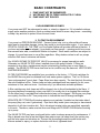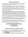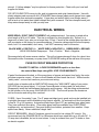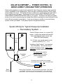
1
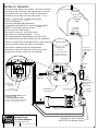
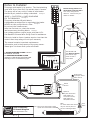
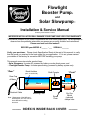
Flowlight
Booster Pump
®
and
Solar Slowpump
™
Installation & Service Manual
© 2003 by Dankoff Solar Products
__________________________________________________________________________
IMPROPER INSTALLATION WILL DAMAGE YOUR PUMP AND VOID YOUR WARRANTY
This manual is based on 20 years of experience with over 5000 pumps sold. We are pleased to
observe how few problems arise when our pumps are properly installed and maintained.
Please read and save this manual!
RECORD your MODEL # ______ - ___ SERIAL # _______
Verify your purchase: Please check Specification Sheet at the end of this manual, to verify
that the pump you received is the best model for your application. If it is not, please contact
your dealer or the factory for correction BEFORE installing your pump.
This manual covers two similar product lines:
• Solar Slowpump for water lift, powered by battery or solar-direct power, and
• Flowlight Booster Pump for water pressurizing, powered by battery system only.
“Rear”
Brush Holders
Shaft Coupler
(one on each side)
“Front”
Rear Cap
of Motor
Pump Head
Motor
Electrical Cable
Mounting Foot
Round
Plate
Note: Slowpumps of the1400 and
2600-Series, and 115 Volt AC
have different mounting
structure.
Dry Run
Switch
(optional)
clamps here
——— INDEX IS INSIDE BACK COVER ———
1
BASIC CONSTRAINTS
I. PUMP MUST NOT BE SUBMERSED
II. WATER MUST BE FILTERED ABSOLUTELY CLEAN
III. PUMP MUST NOT RUN DRY
I. NON-SUBMERSIBLE PUMPS
Your pump must NOT be submerged in water, or rained or dripped on. If it is installed outdoors,
supply some weather protection, such as a sheet-metal shield or even a dog house – something
to keep it dry and also to protect it from the sun’s heat.
II. FILTRATION REQUIREMENT
Your pump is a PRECISION MACHINE. Traces of sand, clay, rust or other solids will cause
rapid wear or immediate damage, just as they would in your automobile engine. If your water is
CRYSTAL-CLEAR ALL THE TIME, our Fine Intake Strainer will provide sufficient protection. If
you have an intake strainer already, it is probably not fine enough -- openings must be no more
than several hairs wide, or additional filtration is required. Since water conditions are subject to
change, it is good insurance to use a filter regardless. Many dealers refuse to sell our pumps
without a filter since it minimizes call-backs.
Our 30-INCH INTAKE FILTER/FOOT VALVE is necessary for pumps lowered into wells.
Otherwise our INLINE FILTER is best, installed close to the pump's intake. If filters are
expected to clog often, maintainance may be minimized by plumbing two or more filters in
parallel. The INLINE FILTER has a clear bowl so its condition may be observed. KEEP SPARE
CARTRIDGES HANDY!
FILTER CARTRIDGES are available from your dealer or the factory. 9 7/8-inch cartridges for
the INLINE filter may also be obtained from local water system suppliers. The 5 or 10-micron
"spun polypropylene" type is best. Paper filters have less capacity. The kind that look like string
has more restance to flow. Carbon taste and odor cartridges have less capacity for dirt, more
resistance to flow, and cost more. Use them only if you have taste and odor problems.
A filter cartridge may look clean and still be clogged, due to fine silt embedded in the fibers. If
the pump becomes increasingly noisey over time, it is usually due to a clogging filter cartridge.
On the other hand, a cartridge that looks discolored may not be clogged. As long as your pump
runs quietly, the filter is OK. Use pump noise to indicate the need to change cartridges.
IRON PIPE OR FITTINGS will introduce abrasive rust particles if installed on the intake side of
the pump (they rust, even if galvanized). Pipe that is dirty inside (even new pipe) or has mineral
deposits in it will also introduce dirt. Dirt is introduced as pipe joints are assembled, especially
in a trench. Therefore, make sure inlet lines and fittings are FLUSHED CLEAN before hooking
up to pump.
The INLINE FILTER may have a red push-button valve to release pressure for maintenance. If
filter is placed more than a few feet higher than water source (at lowest level) the suction may
pull the valve open and introduce air. Prevent this by sealing around the push-button with
silicone sealant or epoxy, or replace the button with a nut, tightened down.
2
III. PUMP MUST NOT RUN DRY
Water is the lubricant for your pump. If it runs completely dry, it will overheat and fail.
DRY RUN SWITCH is an optional accessory to prevent damage from dry run. It is a small
device with two wires that attaches to the front of the pump. It senses temperature, and
switches the pump off before it gets too hot. If you are pumping from a tank, cistern or any
water source that can run low accidentally, a Dry Run Switch should be used. If it saves a
failure once in 10 years, it's worthwhile.
WARNING The dry run switch must be clamped tightly to the front (red plate) of the pump. Its
round metal surface MUST press firmly against the red plate or it will not function. If you can
slip a piece of paper between the switch and the red plate, it is not making sufficient contact.
Loosen the clamp and press the brackets further onto the pump so the contact is tight.
OPERATION The red push-button pops out if the pump runs dry. Push it in to reset the switch,
after water is restored.
A FLOAT SWITCH placed in the supply tank is an alternative to the Dry Run Switch. The
advantage is that it will reset itself when water rises, and will not allow the pump to lose prime.
The disadvantage is the need to run a power cable to the switch -- OK if distance is short.
Please call your dealer or the factory if you have questions.
WARNING Do NOT use a “LOSS OF PRIME” PRESSURE SWITCH for dry run protection.
This is a pressure switch with an automatic shut-off lever. It will NOT function with this type of
pump. Your pump will push sufficient air to maintain pressure, holding the switch on.
PLUMBING SYSTEM DESIGN
If you are not experienced in water supply design and installation, you may wish to seek
professional assistance. Many people are surprised to find how "complex" water system
design can be.
See diagrams on p. 20, for typical groundwater installations.
MINIMIZE SUCTION LIFT to just a few feet, if possible. The practical suction limit for any pump
is 20 vertical feet at sea level (subtract 1 ft. for every 1000 ft. of elevation). The more you
minimize suction lift, the more reliable and quiet your pump will be. Just be sure the motor will
not be submerged if the water level rises, or it will be ruined. Your pump may be placed
DOWNHILL from your water source, if feasible.
YOUR INTAKE PIPE may run any reasonable horizontal distance, although it is BEST TO
KEEP IT SHORT. (We know of installations where the pump is placed 200 feet from the water
source, using 1 1/2" pipe.) USE LARGE PIPE for the intake (1 to 1 1/2" for larger Slowpumps or
Booster Pump).
Slope the intake line from the water source UP toward the pump. AVOID HUMPS in the intake
line. They trap air pockets which can block the flow. AVOID LEAKS IN SUCTION LINE. They
are hard to locate and will cause constant problems.
3
INTAKE PIPE MUST BE SIZED GENEROUSLY to allow no more than a slight pressure drop at
peak flow rate, or pump will be noisey and will wear rapidly. USE PIPE REDUCER FITTINGS to
adapt your pump's inlet or outlet to larger pipe size where necessary. Excessive pipe sizing will
do no harm!
INTAKE MUST NOT BE RESTRICTED by undersized pipe, excessive suction lift, or a
CLOGGED FILTER. Excessive suction at the pump intake causes CAVITATION (formation and
implosion of vapor bubbles). This causes very loud buzzing noise and RAPID PUMP WEAR. A
slight buzzing noise is acceptable, if it cannot be avoided.
DO NOT USE THIN-WALL HOSE or soft tubing on the pump's intake. It may collapse under
suction and restrict the flow. Do not use polyethylene pipe (black flexible) for the suction either.
It is prone to slight leakage at the fittings.
INLINE FILTER should be mounted HORIZONTALLY and as low as possible. This prevents
any air trapped in it from blocking the water flow. Be sure to leave some space below it for a
pan, to catch water when replacing the filter cartridge.
FOOT VALVE is a check valve installed at the water intake. It is required in any case where the
pump is located higher than the low-water level in the source. We recommend a high quality
spring-loaded type to avoid loss of prime. A check valve allows water to flow one way and not
the other. Be sure to install it the right way! Our 30” Intake Filter or Fine Intake Strainer Foot
Valve accessory is recommended. These prevent debris from catching in the foot valve and
causing loss of prime.
REMOVE FOAM PLUGS BEFORE CONNECTING PIPES. New pumps are packed with foam
plugs to prevent contamination.
PRIMING YOUR PUMP: Priming a pump means filling its intake and suction line completely
with water. This must be done if the pump is mounted higher than the water source. A
removable plug or a valve must be installed at the highest point is in the suction plumbing.
Prime the pump and intake line by pouring water into the opening until it is completely full. Your
foot valve prevents loss of prime by not allowing water to flow back into the water source.
Your pump will create enough vacuum to SELF-PRIME to around 10 feet (less at high
elevations), but only when it is in new condition and wet inside. A priming plug is always
recommended if the pump is to be located higher than the water source. (EXCEPTION -- see
"Installation in Deep Well Casings"). You may use a good quality ball valve instead of a plug, if
frequent priming is expected.
A CHECK VALVE AT THE PUMP OUTLET is required if there is more than a 30 foot lift above
the pump, or in any pressurizing system. This allows the pump to start easier. It also prevents
back-flow when changing filter cartridges.
PIPE UNIONS: If you run rigid piping (copper or PVC) directly to the pump, unions are required.
Unions make pump replacement easy, without the need to cut and re-solder or re-glue the pipe.
"Copper Flex Connectors" commonly used for water heaters may be used instead. However:
Do NOT use them for the larger Slowpumps (2507, 2607) or Booster Pump. They are too
restrictive.
4
MOUNTING YOUR PUMP
Locate your pump in a cool place. Do not allow direct exposure to sunshine during operation, or
the motor may overheat. Allow free flow of air around the motor for cooling. SHELTER IT
FROM RAIN AND SUN, or it will be a mess in a few years.
The pump may be mounted horizontally or vertically. If vertically, FACE THE PUMP HEAD
DOWNWARD. RIGID MOUNTING IS NOT required in most installations. In a non-battery
system, starting is gradual and the pump does not jerk with the start. In a battery system, it will
jerk slightly, but simply mounting it to a small wooden board is sufficient to stabilize it. The
pump may be hung vertically on a rope. Observe the pump and see that it is not likely to
overstress or loosen pipes as it starts. DO NOT mount the pump directly to a wall or wood floor
in your home. It will increase the noise.
CHANGING PUMP HEAD POSITION: If you wish to face the pump's fittings sideways or
downward, you may rotate pump head to a different position by removing the four bolts that
secure the pump to the motor. If your pump looks like the picture on P.1, do this: Remove the
four hex-head bolts from the round plate, then rotate pump head to new position. REALIGN
THE PUMP AND MOTOR SHAFTS, or the coupler will bind and wear. This is simple. When
you remove the round plate, notice that the bolt holes are oversized for alignment adjustment.
Reposition as desired, but leave the bolts loose. BEFORE installing the pump, drop a teaspoon
of water into the inlet and run the pump (on 12 volts is OK for the 24v pumps). Slide the plate
around so it settles into the position where there is NO VIBRATION, then tighten the bolts firmly.
HANDLE YOUR PUMP CAREFULLY! Never hammer on it, clamp it in a vice or drop it. Pumpmotor alignment is critical. DO NOT DISTURB THE ALLEN-HEAD BOLTS holding the
mounting plate to the motor UNLESS you wish to rotate the pump head to a different position.
The shaft coupler between the motor and pump should turn easily using two fingers.
Sometimes after a period of dry storage, the pump will stick. If you can't turn the coupler, put a
bit of water in the pump intake and turn the coupler with pliers to "crack" it loose. Do this by
turning it BACKWARDS. If it sticks again, see “Troubleshooting”.
IF YOU ARE NOT EXPERIENCED WITH WATER SUPPLY
INSTALLATION, PLEASE CONSULT LOCAL SOURCES regarding:
(1) Freeze protection
(2) Choice and sizing of pipe
(3) Plumbing design in general.
INSTALLATION IN A DRILLED WELL CASING
INSIDE A 6-INCH WELL CASING, SPECIAL ELBOWS ADAPTERS are required. The elbows
fit 1/2" polyethylene (black flex) pipe. MEASURE CAREFULLY to determine the length of pipe
you need. SUBTRACT 1.5% TO ALLOW FOR PIPE AND ROPE STRETCH.
Assemble according to diagram. A priming plug is not needed. Before lowering the pump,
place the intake into a bucket of clean water and run the pump until water exits. Now it is
5
primed. A "pitless adapter" may be optimum for freeze protection. Check with your local well
supplier for details.
POLYETHYLENE PIPE comes in rolls, and is inexpensive and quite freeze-tolerant. Use with
plastic adapters and secure with ALL-STAINLESS hose clamps (obtain such clamps from a pipe
supplier rather than automotive supplier). If pipe does not stretch tightly over fittings, warm it
with a torch or hot water then tighten clamps firmly with a wrench. Use two clamps at each joint.
Keep extra clamps handy in case you strip one.
ELECTRICAL WIRING
WIRE SIZING: DON'T CHEAT YOURSELF with undersized wire! Your pump is wired with a
short length of #14 or #12 cable. This size is sufficient for short lengths only. Splice it to a
larger size of wire if your wire run is longer than 15 feet. Consult a low voltage wire size chart or
call your dealer or the factory for recommendations. Excessive voltage drop will slow the pump
down, but if it is unavoidable, don’t worry. It will NOT cause any harm to the motor.
BLACK WIRE = POSITIVE (+) WHITE WIRE = NEGATIVE (-) GREEN WIRE = GROUND
1400 & 2600-Series Slowpumps: Red = Positive Black = Negative
Reverse polarity will cause reverse rotation. This will not cause damage if done for a short time.
Reverse the wires if necessary so pump turns CLOCKWISE looking at the red face of the pump.
FUSE OR CIRCUIT BREAKER PROTECTION
FAILURE TO INSTALL A FUSE OR BREAKER equal to or less than
the motor's Max Amps rating WILL VOID YOUR WARRANTY.
If water flow becomes blocked, or if the pump jams or freezes and cannot turn freely, the motor
will draw excessive current. A fuse or circuit breaker will then break the circuit. Without such a
"safety valve", a minor fault can burn your motor and wiring.
Install a fuse or breaker with an AMP RATING close to the "MAX AMPS" rating of your motor,
OR LESS (but not more higher). If a Linear Current Booster is being used (for array-direct
Slowpumps) install the fuse between the booster and the pump. Use the rating recommended
for the booster or for the pump, WHICHEVER IS LESS. This fuse will protect the booster as
well as the motor and wiring from overload.
FUSES: Use a “time-delay” type. The 3" paper cartridge type is good, and may be installed into
a raintight disconnect switch available at any electric supplier. An automotive in-line fuse holder
is fine for 12 or 24V systems. Automotive blade fuses (type ATC) are prefered over glass fuses.
They have sufficient time-delay. (Time-delay glass fuses are available from ELECTRONIC
suppliers only, not automotive.) Use good quality fuse holders, protected from weather. Keep
spare fuses handy. Never substitute a larger fuse!
CIRCUIT BREAKERS: Most AC breakers cannot be used for low voltage DC circuits. We
recommend only the SQUARE-D® QO or QB-series which been rated safe up to 48 volts DC. A
10 amp size is available, but not in most stores. It may be ordered from your PV dealer or from
an electric supplier.
6
Install the fuse or breaker at the power source, to protect the wiring as well as the motor. If the
circuit is protected by a breaker, then any additional fuse may be installed at the motor.
THERMAL OVERLOAD
If your pump resembles the illustration on P.1, a THERMAL SWITCH is mounted on the rear of
the motor (inside the white cap) to shut off the motor if it approaches an overheat condition. If
this happens, it will turn back on after a cooling period of about 20 minutes. If overheating
occurs during normal operation of the pump, it may be because it is working beyond it’s
capacity. See Troubleshooting.
The Flowlight Booster Pump, Standard Model may overheat if it is running for more than 20
minutes at a pressure exceeding 50 PSI. It will cool and reset automatically.
GROUNDING and LIGHTNING PROTECTION:
A long wire run may act like an antenna, receiving induced surges of high voltage when lightning
is present. Proper grounding will greatly reduce risk of lightning damage to your power system.
A proper ground system consists of a minimum of one 8 ft. copper-plated ground rod driven into
the ground, preferably in a moist spot close to the PV array. Or, if you have a steel well casing,
drill and tap a bolt hold to make good contact to it.
In a dry, lightning-prone location, use more than one ground rod at least 10 ft. apart. Bury bare
copper wire between them. Use min. #8 ground wire (larger for distances exceeding 20 ft.). In
a rocky location, where ground rods can't be driven, bury (as much as feasible) 150 feet (total)
of bare copper wire, radiating out in two or more directions from the PV array. Try to contact
moist earth as much as possible. Use only the copper or bronze electrical connectors designed
for grounding application, and BE SURE ALL CONNECTIONS ARE TIGHT.
Connect your ground system to the METALLIC FRAME of your PV array via min. #8 copper
wire. Also ground metallic support structures and electrical enclosures. For non-battery pumps,
we have observed the least lightning damage where only the mechanical structure is grounded - NOT an electrical conductor. This may vary from electrical codes. Call the manufacturer of
your controller, if you have questions.
WATER LEVEL & FLOW CONTROL
FLOAT SWITCHES/WATER LEVEL SENSORS: These are devices that sense high or low
water level and switch your pump on and off. Ask your dealer or factory about these. Most
switches rated for 15 AMPS at 230 VAC are fine for your DC pump.
FLOAT CONTROL IN WATER SOURCE may be used if dropping water level is causing dry run
or excessive suction (noise due to cavitation).
FLOAT CONTROL IN STORAGE TANK may be used to turn pump off when tank fills. This
eliminates tank overflow and reduces pump wear and filter changing.
REMOTE FLOAT CONTROL when tank is a LONG DISTANCE from pump may be done in
three ways:
(1) Small wire buried from tank/float switch to pump actuates a relay at the pump.
(2) Very small wire from sensor in tank actuates "Water Level Sensor" option in your pump
controller (LCB). This is for non-battery systems only.
7
(3) Float valve in tank restricts flow. Pressure builds up and actuates pressure switch at
pump. Small captive-air pressure tank is necessary at pump to prevent "switch chatter".
Contact your dealer or the factory for further advice.
FLOW RESTRICTION MUST NOT BE USED as a method to reduce your pump's flow rate. It
may result in excessive pressure build-up and current draw.
Flowlight Booster Pump Installation
®
For Pressurizing Systems
A PRESSURE TANK IS REQUIRED with a Booster Pump system. PRESSURE TANKS are
available from local water supply dealers. Use the largest tank that you are willing to buy. 40
gallon size is typical -- it allows you about 12 gallons of water between pump cycles. Those 12
gallons may be drawn at a higher flow rate than the pump produces. A large pressure tank will
minimize on/off cycling of the pump. In a typical household of more than four people, a tank of
at least 60 gallons is recommended. The bigger the better! More than one tank may be
connected. They need not be the same size.
A PRE-CHARGED "CAPTIVE AIR" TANK is recommended. Cheaper "galvanized tanks"
require periodic recharging, store less water between cycles, and don't last as long. PROPER
PRE-CHARGE IS ESSENTIAL. Follow the instructions that come with your pressure tank –
With presure discharged from the tank, adjust pre-charge to 2-3 PSI below cut-in pressure. This
will assure that you get the best performance from your system.
Installation from cistern or
storage tank where pump is
higher than the water source
8
NOTE: It is preferable to place the pump LOWER than the water level in the tank. This
illustrates an alternative, not an ideal. Note the upward rise of the suction pipe, the high position
of the priming plug, and the horizontal position of the filter. These measures help prevent air
entrapment that restricts flow and causes pump noise.
Follow your pressure switch instructions for wiring. Use the flexible hose that comes with your
Booster Pump (cut it into two sections). Our Easy Installation Kit contains the tee fitting at the
tank, a DC-rated pressure switch, and all of the small parts shown between the pump and the
house plumbing. See PRESSURE SWITCH DIAGRAM on PAGE 20
Typical Flowlight Booster Pump installation
Illustration by Home Power Magazine
PRESSURE SWITCH ADJUSTMENT: Switch settings determine the pressure range of your
system. To conserve energy, set the pressure as LOW as feasible. This will also prevent the
motor from overheating if you run it for long periods -- sprinkling, for example. Low pressure
(even 15-20 PSI) may deliver excellent water flow IF your plumbing and hoses are sized larger
than minimum. If not yet plumbed, use at least one size larger pipe than conventional, and
avoid restrictive connections such as 3/8" tubing often used to feed sinks.
Adjustment: Start with the standard setting (usually 30/50 PSI). Reduce the pressure according
to your requirements, if you wish. It is wise to measure the current used by your pump (with an
amp meter in series with the line, your system metering). Current draw will rise in direct
proportion to outlet pressure. Pressure should NOT be set beyond 50 PSI MAXIMUM (65 PSI
with 2910 Model) or loss of efficiency and motor over-heating will result. IMPORTANT: After
any change to your cut-in pressure, you need to readjust the pressure tank pre-charge.
9
If you are raising water vertically AND pressurizing, note the relationship: 2.31 ft. = 1 PSI.
Example: A pump that lifts 23 vertical feet and pressurizes to 30 PSI must pump a total of 40
PSI. Total lift = vertical distance from water surface to pressure tank.
WARNING: INSTALL THE PRESSURE RELIEF VALVE INCLUDED WITH YOUR PUMP!
Flowlight Booster Pumps are supplied with a 75 PSI Pressure Relief Valve as a safety feature.
If your pressure switch fails, EXCESSIVE PRESSURE may cause your tank or piping to burst
and flood your home. (A properly sized fuse or circuit breaker should shut pump off before relief
valve opens BUT many breakers are not accurate, and the proper fuse may not always be
present.)
INSTALL THE PRESSURE RELIEF VALVE near your pressure tank (at the "Accessory Tee"
shown in diagram). Run a pipe or hose from its outlet to a drain or drain pipe or to the outdoors
where water can drain away safely.
A GATE VALVE and DRAIN VALVE are recommended (see diagram) for convenience during
system shut-down. The drain valve is simply a garden hose outlet which allows easy draining of
the system. It also allows water delivery by hose while water is shut off to the house during
installation or repairs to plumbing.
EASY INSTALLATION KIT IS AVAILABLE!
If you have not yet purchased the small parts you need to install your Booster Pump, you can
save time and confusion by purchasing our convenient Easy Installation Kit. Pipe components
are brass to resist corrosion. The kit includes pressure switch, pressure gauge, tank tee, shutoff
(ball) valve and hose bib (drain valve) plus the necessary pipe nipples. Order Dankoff Solar Item
#20200
VENTILATION SLOTS are located on bottom of motor for cooling (Standard Model Booster
Pump only). If you are concerned with insects building nests inside your motor, glue some
screen over the slots. Silicone sealant works best for this.
FLOWLIGHT BOOSTER PUMP requires a BATTERY SYSTEM, NOT A PV ARRAY-DIRECT
installation. PV ARRAY voltage may exceed 15V and overspeed the pump.
10
SOLAR SLOWPUMP — POWER CONTROL for
ARRAY-DIRECT (NON-BATTERY) OPERATION
When working against a constant head (vertical lift) Solar Slowpump requires nearly constant
current, regardless of the voltage/speed. When low light conditions are present, the PV array
cannot supply full current. The voltage will drop to nearly zero, and the pump will “stall” (like a
truck trying to start in 4th gear). The remedy is either to add a PUMP CONTROLLER, also
called LINEAR CURRENT BOOSTER (LCB) to your system. This device will match the power
source to the load by transforming the voltage down while increasing the current delivered to the
motor (like an automatic transmission). If you are not using a controller in your non-battery
system, contact your dealer. It will greatly improve low-light performance.
System Wiring for Typical Slowpump Installation
-- Non-battery System --
+
For 12 Volts, use a single panel, or wire
panels in parallel (+ to +, - to -).
PV
Array
-
+
•
•
•
“Series” Wiring is shown, for nominal 24V
system: Voltage from panels will read 40V
when disconnected (open circuit), and
about 30V while pumping.
on
Installing a Solar Tracker? Use stranded
wire for flexibility. Secure the wires to
tracker with plenty of tape. Make a long
slack loop to allow free motion of tracker.
The proper fuse must be
i nserted inside the LCB to
protect the pump from
overload.
Controller
(LCB)
off
• •
•
for backup power or testing using a battery,
hook jumper wires here , not to controller input.
Pump
Earth
Ground
Remote Tank Float Switch: See your controller instructions. Float switch
must MAKE contact on rise, to turn the pump OFF. This is opposite of
normal action, so your float switch may be labeled “pump down to empty”.
11
WATER USAGE
WATER CONSERVATION = ENERGY CONSERVATION
+ LESS FILTER MAINTENANCE
TOILETS: A 1.6-gallon flush toilet may reduce total domestic water consumption by 50%
compared with typical 4-5 gallon toilets. They are now standard in U.S.A.
IRRIGATION SYSTEMS: Many drip, trickle or flood irrigation systems will function on LOW
PRESSURE. It is wasteful of energy to supply pressurized water where it is not required. You
may wish to arrange separate gravity flow from your water source or storage tank, if possible.
Or, if a small amount of lift/pressure is required, consider a low-pressure DC pump such as a
marine bilge or circulator pump.
LOW FLOW SHOWER HEADS are recommended IF you are running 30-50 PSI pressure
range. At lower pressures, they may not provide adequate flow.
FREEZE PROTECTION
If freezing of your outlet pipe is to be expected, you may avoid the frequent necessity of
replacing fuses or resetting your breaker by installing an ADJUSTABLE PRESSURE RELIEF
VALVE at the pump outlet. This will allow water to flow back into the well when outlet pipe is
blocked. Order the valve from your dealer or any electric or plumbing supplier (Grainger's part
number 1X624 or equivalent, about $15). To adjust, be sure water has reached the highest
point in your system. Loosen the valve til it leaks water, then tighten it gradually JUST PAST
the point where it stops. Be sure water will not drip onto the motor/pump.
To PREVENT freezing of exposed pipes (Slowpump system) you might consider the primitive
method of drilling a small "weep hole" in the outlet pipe, below ground level. The pipe will drain
when pumping stops but a small amount of water will be wasted during pumping. Set the outlet
pipe to spill into the top of the tank so that the tank will not drain, or install a check valve and
"vacuum breaker" to allow pipe to drain.
Water WILL drain back through the pump if allowed to, but it will do so slowly. If this is desired,
do not use any check valves or foot valve. Pump must have suction draw of no more than a few
feet, however. If pump drainage is required, position pump vertically (head downward) or
horizontally with intake and outlet facing downward (see "Changing Pump Head Position", p.5).
Take every precaution to PREVENT pump freezing. The forged brass pump head will survive
most light freezes, but a hard freeze may damage it. If you insulate your pump for freeze
protection, keep the motor exposed so it won’t overheat.
12
MAINTENANCE
INTERNAL INTAKE SCREEN: The pump has an internal metal intake screen. It's purpose is
to catch solids accidently introduced during installation or filter servicing, dirt stuck inside your
intake pipe before installation, or mineral deposits that may accumulate and flake off of the
intake piping.
1300-SERIES "SLOWPUMP" has an angled extension with a large brass nut on the end.
Remove the nut to inspect and empty screen.
2500-SERIES SLOWPUMPS & "FLOWLIGHT BOOSTER PUMP" have a strainer pushed into
the intake fitting.
EXTERNAL FILTRATION IS STILL REQUIRED! If you notice signs of intake blockage, inspect
your screen. If solids keep accumulating, improve your filtration. See Page 2 for details about
filters and cartridges.
PUMP HEAD: Except for the internal screen, your pump head is maintenance-free. DO NOT
remove its front plate or otherwise tamper with it unless you are intending to get it rebuilt. The
pump head is NOT USER-SERVICEABLE. It is easy to dissemble, but difficult to reassemble
without special tools.
WATER FILTER:
The best way to determine when a cartridge is becoming clogged is to listen for an increasingly
loud buzzing noise (cavitation). It is difficult to determine the condition by the appearance of the
cartridge. KEEP SPARE CARTRIDGES! You can buy cartridges locally, but the best ones are
thick-body polypropylene fiber construction (not the type that looks like twisted string or paper).
We recommend 10-micron cartridges (pack of two: Dankoff Solar Item# 20236). Do not use a
carbon filter for this purpose.
30" INTAKE FILTER, WARNING: Cartridges vary slightly in outside diameter. If replacement
fits loosely into end caps, wrap ends with cloth or tape to make a snug fit. If cartridge is too
large to fit, peel away some fibers using a knife. End caps MUST fit snugly or dirt will enter!
Pack of 3 cartridges: Dankoff Solar Item #20237.
MOTOR BRUSHES: After a year or two, inspect your motor brushes and measure their length
(remove one or both of the black plastic screw heads near the rear of the motor). Motor
brushes on most models measure 3/4 inch long, not including the rounded end. If you have a
1/2 HP model (1400 or 2600 series, or any motor larger than 5” diameter) they begin life
measuring about 1 1/4”). After they show some wear, you may calculate how many more years
they have left before they are too short. After inspecting a brush, replace it in the EXACT SAME
POSITION and tighten the plastic screw GENTLY. Most brushes last at least 5 YEARS of daily
running. Brush wear will not effect motor performance until contact is suddenly lost.
MOTOR BRUSHES for 12V pumps: Dankoff Solar Item # 20301
MOTOR BRUSHES for 24V pumps: Dankoff Solar Item # 20302
For 1400 and 2600-series pumps (large blue motor) and for AC models, please ask your
Dankoff dealer.
13
TROUBLESHOOTING
BEFORE YOU CALL FOR HELP,
TRY TO LOCATE YOUR PROBLEM HERE:
Please note the terms “Front” and “Rear” -- See P. 1 illustration
PUMP WILL NOT FIT INTO YOUR 6" DRILLED WELL CASING: Close Elbow fittings are
required (Dankoff Solar Item #20308).
PUMP DOESN'T TURN ON -- NO POWER: (1) CHECK DRY RUN SWITCH on front of pump,
if present. Press red button to reset. Correct the cause of dry run. (2) CHECK FUSE or
BREAKER and any control or wiring devices in line. (3) MOTOR STARTS WHEN YOU HIT IT:
Sticking brushes -- "Motor Brush Problems" (4) Remove rear cover of motor to check
connections there. Check for voltage present at motor. If voltage is present, see next entry. (5)
CHECK THERMAL OVERLOAD SWITCH on rear of motor. Bypass it by holding a piece of wire
across its terminals. If motor runs (and is not hot) replace thermal switch. DRY RUN SWITCH
may be tested the same way.
PUMP SPINS BUT DOESN'T PUMP WATER: (1) CHECK DIRECTION of rotation. If not
clockwise (viewed from brass front-end) reverse polarity. (2) CHECK PRIME: Open priming
plug or valve (see instructions). Pour water in. LOSS OF PRIME/INTAKE PIPE LEAKAGE:
CHECK ALL FITTINGS -- a pinhole leak in suction pipe will cause loss. FOOT VALVE may
leak. Inspect, pressure-test, clean or replace. Debris may be stuck in foot valve causing leak if
not protected by fine screen or intake filter. REGARDING POLYTHYLENE PIPE FITTINGS: If
pipe does not stretch tightly over fittings, it may leak. Gently heat with torch or hot water and
retighten hose clamp WITH WRENCH. Replace stripped clamps. Use ALL-STAINLESS
clamps.
NOISY PUMP:
NOISE = CAVITATION = RAPID PUMP WEAR
FIX THE PROBLEM!
STEADY BUZZING SOUND Indicates EXCESSIVE SUCTION due to any combination of (1)
HIGH SUCTION LIFT -- mount pump as low as possible, (2) UNDERSIZED SUCTION PIPE, (3)
CLOGGED FILTER -- NOTE: Fiber filter cartridges may be clogged and LOOK CLEAN (fine silt
is hidden within the fibers). (4) CLOGGED INTERNAL INTAKE SCREEN. See next two entries.
(5) SOFT, FLEXIBLE HOSE used on intake line may be crushed or kinked by suction -- replace
with more rigid pipe material.
UNSTEADY BUZZING SOUND Indicates LEAK IN SUCTION LINE allowing AIR to enter. (1)
Check for bubbles in in-line (transparent) filter or air in outlet water. (2) See LOSS OF PRIME in
above entry. (3) If you have IN-LINE FILTER with red Pressure Relief Valve (red button) on top,
and it is mounted several feet above water source, air may be drawing in around the valve.
SEAL AROUND THE VALVE with silicone sealant or epoxy glue OR unscrew the red button and
replace it with a nut, tightened. (4) If no source of air leakage is present, water may have high
concentration of DISSOLVED GASSES which release as bubbles in suction pipe. Reduce
suction lift if possible. Install air chamber in intake line, with valve on top. Pour water in to
replace air when problem reappears. (5) Turn filter to a horizontal position. This allows bubbles
14
to get out of the way of flow. Do NOT turn it upside-down, or dirt may fall in when filter is
changed.
NOISE AND VIBRATION IN PIPES (pressure gauge vibrates extremely): One of four vanes
in the pump is broken. Pump head must be rebuilt -- See Rebuild/Exchange Service. There
should be almost no vibration of pressure gauge needle.
FILTER CLOGS FREQUENTLY: (1) INTAKE TOO CLOSE to bottom of well, stream, tank etc.
Raise it as high as feasible to reduce intake of dirt. (2) IMPROVE THE DEVELOPMENT of the
water source -- channel water into a settling tank, clean tank periodically. (3) Install a larger
filter, or plumb two filters parallel to each other.
CLOGGED INTAKE SCREEN: Safety screen is located at the pump intake. Remove large nut
(1300-series) or intake fitting (2500-series or Booster Pump) to inspect and clean screen. (1) IF
YOU DON'T HAVE A CARTRIDGE-TYPE FILTER, INSTALL ONE NOW! (2) If screen is
clogged with fibers from filter cartridge, use higher quality cartridges. (3) If screen is clogged
with rust deposits, replace iron pipe or fittings with plastic, copper or brass. (4) If mineral or
corrosion deposits are clogging screen, install filter as close as possible to pump intake. Ask
local water professionals what type of pipe is least susceptible to mineral accumulation and
corrosion in your area.
FILTER IS CLOGGED AND YOU DON'T HAVE REPLACEMENT: (1) IN-LINE FILTER:
Purchase common "Rust and Sediment" fiber-wound cartridge at local hardware store or
pump/well supplier. (2) 30" INTAKE FILTER: Obtain spares from your dealer, factory or
industrial suppliers. In emergency, purchase 3 ordinary 10" fiber filters (not paper) from local
source. Glue them end-to-end with epoxy and install. (3) TRY BACK-WASHING filter by
blasting it with pressure from the inside. For 30" intake filter, remove check valve and attach
garden hose adapter. Back-washing is effective on coarse, sandy material but is NOT effective
with clay, rust, very fine or sticky deposits.
PURCHASE SPARE FILTERS. NEVER RUN PUMP WITHOUT A FILTER!
LOW FLOW RATE -- PUMP TURNS FAST, DRAWS LOW CURRENT: Pump is worn out from
dirt, rust or other abrasive particles in water, or from cavitation, from running dry, or just from
age. REPLACE PUMP HEAD. See "Rebuild/Exchange Service".
BOOSTER PUMP TAKES LONG TIME TO REACH CUT-OFF PRESSURE: (1) If pump spins
fast, see above entry. (2) If pump rotation slows way down as pressure builds, wire is too small.
Consult low voltage wire size chart or ask your dealer for correct wire size.
LOW FLOW RATE -- PUMP TURNS SLOW, DRAWS HIGH CURRENT (may run hot, may
blow fuses): Pump is hard to turn due to: (1) EXCESSIVE VERTICAL LIFT, beyond system's
capacity: Trade pump head for lower volume model, or increase size of solar array if it will not
overpower the motor -- see Specifications Chart. (2) MISALIGNMENT: Pump plate was
removed from motor and not readjusted after assembly. See "CHANGING PUMP HEAD
POSITION", p.5. Check rubber shaft coupler for damage. (3) MINERAL DEPOSITS: Turn
shaft with two fingers. Will be hard to turn. Use vinegar, or whatever solution works to dissolve
the mineral deposits in your plumbing. Remove pipes from pump and allow solution to circulate
through pump by turning it backwards. If this doesn't work, or if pump has been damaged,
replace or rebuild.
15
PUMP CYCLES ON AND OFF ABOUT EVERY 20 MINUTES: MOTOR IS OVERHEATING.
Thermal switch on back of motor is working. (1) HIGH CURRENT DRAW: See above. (2) NO
VENTILATION: Motor must have FREE AIR FLOW to prevent overheating. Do not wrap with
insulation. (4) Motor is exposed to sun or other heat source -- keep it cool. (5) BAD THERMAL
SWITCH: Motor should shut off at approximately 140 degrees F. If motor smells or is too hot to
hold your hand on for 3 seconds, replace thermal switch and check for overheat damage. If
motor is not getting so hot (you can hold your hand on it for 5 seconds) replace thermal switch.
NOTE ON BOOSTER PUMP: STANDARD MODEL may overheat if run continuously (periods
over 20 minutes) at pressures exceeding 50 PSI. This may happen while running irrigation.
Observe pressure gauge and open valve(s) for higher flow so that pressure drops below 50 PSI,
or reduce your pressure switch setting. The thermal switch protects the motor from damage.
BOOSTER PUMP CYCLES ON AND OFF EVERY FEW SECONDS (PRESSURIZING
SYSTEM): PRESSURE TANK MUST be used with system. Pre-charge tank via air fitting to 2
PSI less than cut-in pressure (that's 28 PSI air in a 30-50 system). Turn power off and release
water pressure before setting pre-charge. Modern "captive air" tank will not need pre-charging
again. GALVANIZED TANK (without air bladder) MUST BE RECHARGED with air about once
per year as air dissolves into water. Use tire pump or compressor.
BOOSTER PUMP TURNS ON PERIODICALLY WHEN NO WATER IS BEING USED. (1)
Water is leaking somewhere after the check valve (check valve must be installed at pump
outlet). (2) Check valve leaks internally. Foot valve, if present, also leaks.
LOW FLOW RATE -- PUMP TURNS SLOW, MOTOR COOL: (1) Voltage at motor measures
lower than voltage at source: WIRE IS UNDERSIZED. Consult wire size chart or ask your
dealer. (2) See next entry.
SLOWPUMP RUNS TOO SLOW OR STALLS IN LOW LIGHT (Array-Direct, Non-Battery
System): (1) Solar array or wire is undersized. (2) Linear current booster or similar matching
devices needed to prevent stalling when array current is less than pump requires. Contact
dealer or factory. (3) Current booster not "tuned" properly (if it has an adjustment). Set
screwdriver adjustment for peak performance in LOW LIGHT conditions. See current booster
instructions. (4) Pump may be drawing too much current -- Test: Connect pump to battery(s) of
proper voltage. Measure current draw (amps) and flow rate. Check against chart (Watts = Volts
X Amps). See "Low Flow Rate/Slow/High Current" above, if not close to specifications.
PUMP WON'T TURN, shaft coupler can't be turned by hand. Should blow fuse or breaker: (1)
After a period of disuse or storage, parts may lock up. Grab shaft coupler lightly with pliers and
try turning it backwards. (2) Debris jammed in pump. Disconnect plumbing, pour water into
outlet, and run pump IN REVERSE (by reversing polarity). Watch for debris exiting inlet. Check
performance -- damage is likely. (3) See "Pump Frozen".
PUMP JAMS, MAKES CRUNCHING NOISES, black material in outlet: Internal parts are
broken, either by debris in pump, severe freezing, external shock or just bad luck. See
"Rebuild/Exchange Service".
WATER DAMAGE: MOTOR SUBMERGED OR DRIPPED ON. Inspect brushes and
commutator. If in very poor condition, motor may be beyond repair. Contact factory. If motor
was not run wet for very long, it may need only new bearings, available from factory or from any
16
motor repair shop or bearing supplier. Rough commutator must be turned (resurfaced) on a
lathe. This may be done by a machine shop or electric motor shop. CORRECT THE CAUSE of
damage. If your water level is too unstable, contact your dealer or factory about a submersible
pump.
RUSTY BEARINGS: (1) PUMP HEAD: Steel ball bearing is visible at pump head shaft. Rust
caused by water drip or submersion. Pump head must be rebuilt to replace the bearing (see
Rebuild/Exchange). (2) MOTOR: Replace with DOUBLE SEALED "R8" bearing (front) and
"R6" (rear). These are common bearings available from automotive or electric motor suppliers,
or factory. Any mechanic can do this. (A puller tool or a press is needed for removal.)
PUMP FROZEN BY LOW TEMPERATURE: (It should blow fuse or breaker.) Allow it to thaw.
Observe/test performance. If damaged, replace or rebuild. Check all plumbing for damage and
leaks and protect from future freezing.
RUBBER SHAFT COUPLER FAILURE: MISALIGNMENT between pump and motor shaft due
to removal of pump plate from motor and reassembly without readjustment. See "CHANGING
PUMP HEAD POSITION" on p.5. Replace rubber "spider". Inspect metal coupler halves for
damage and replace if worn. These are common parts available from any electric motor shop,
machine shop, or heating/air conditioning supply, or from factory. Coupler parts will last
"forever" if alignment is correct.
MOTOR BRUSH PROBLEMS: Motor brushes are carbon rods that make electrical contact with
the spinning copper "commutator" on the motor shaft. The two brushes are accessible by the
plastic screws near the rear of motor. They MUST slide in and out very easily -- a spring
pushes them in as they wear. Brushes must be at least 3/8" long (longer on motor larger than
5” diameter). They generally last about 5 years, unless motor has been wet inside (see
"WATER DAMAGE"). Retighten plastic screws gently!
(1) WORN BRUSHES: Call dealer or factory for replacements.
(2) STICKING BRUSHES: Inspect inside each brush holder with flashlight. Clean if corroded
or dirty. If brushes still don't slide in/out without friction, sand down two of the long sides of
brush VERY slightly.
(3) BRUSH SPRINGS WEAK, wire looks overheated: Motor overheated (severe overload, lack
of fuse protection). Replace motor and correct the cause.
(4) BROKEN BRUSH HOLDER: Repair with epoxy, or replace (contact factory). Glue it to
motor shell with EPOXY PUTTY, carefully mixed. To insure proper position, remove rear plate
of motor to see that brush sets into perfect position as glue sets. Glue must be hard and strong.
(5) COMMUTATOR PROBLEMS may be caused by poor brush contact, overheating or water
damage: Com is visible thru brush holders or Booster Pump cooling slots. The wearing surface
should be smooth, with a uniform brown color. If it looks good, DO NOT sand it or do anything to
it. Commutator damage may require resurfacing on a lathe. A local electric motor repair shop or
automotive electric shop can perform these repairs.
17
FACTORY REPAIRS
WHEN CALLING FACTORY OR DEALER FOR HELP,
PLEASE tell us your MODEL and SERIAL NUMBERS !
Most failures involve the pump head, not the motor. This is the brass part that the pipes
connect to. The pump head may be replaced with simple hand tools (a 7/16” wrench and a 1/8”
Allen wrench/hex key).
YOUR PUMP HEAD IS NOT USER-SERVICEABLE. It is delicate and difficult to re-assemble.
Disassembly of your pump head will void your warranty. Individual parts are not available. If
the pump head is faulty, it must be replaced with a new one.
WARRANTY CLAIMS must include receipt to prove date of purchase.
TO SHIP PUMP TO FACTORY FOR REPAIR:
Please call us before shipping anything.
(505) 473-3800
FAX (505) 473-3830
Email: [email protected]
PLEASE tell us your MODEL & SERIAL NUMBERS
******************************************************************
WARRANTY
******************************************************************
Your pump is warranted to be free from defects in material and
workmanship for ONE (1) YEAR from date of purchase.
Failure to provide correct installation, operation, or care for the
product, in accordance with instructions, will void the warranty.
Product liability, except where mandated by law, is limited to repair or replacement, at the
manufacturer's discretion. No specific claim of merchantability shall be assumed or implied
beyond what is printed on the manufacturer's printed literature. No liability shall exist from
circumstances arising from the inability to use the product, or its inappropriateness for any
specific purpose. It is the user's responsibility to determine the suitability of the product for any
particular use.
In all cases, it shall be the responsibility of the customer to insure a safe installation
in compliance with local, state and national electrical codes.
18
Explanation: The National Electrical Code® specifies that switches not disconnect the
“grounded conductor”, which is the negative. So, we are switching only the positive. Using both
sets of contacts as shown (in series) will extinguish the arc (spark) that forms when the contacts
break. This greatly increases switch reliability.
19
Other solar and DC water pumps
————————————————
SUBMERSIBLE PUMPS FOR SURFACE AND DEEP WATER
LIFT AND PRESSURIZING
ETAPUMP® SOLAR SUBMERSIBLE
32 GPM at 25 FEET
1.7 GPM at 650 FEET
High-tech, maintenance-free
————————————————
SURFACE PUMPS FOR LIFT AND PRESSURIZING
SOLAR FORCE™ PISTON PUMP
5-9 GPM to 230 FEET or to 100 PSI
Extremely rugged and dirt-tolerant
SUNCENTRIC™ CENTRIFUGAL
5-70 GPM to 90 FEET
Also for circulation for swimming pools,
pond management, solar heating, and more
SOLARAM™ SURFACE PUMP
3-9 GPM to 960 FEET
————————————————
Ask your Dankoff dealer or go to
www.www.innovativesolar.com
20
INDEX
Topic
Page
Diagrams
Booster Pump system
Check valve
Circuit breaker
Dry Run Switch
Easy installation kit
Factory service
Filter, cartridges
Filter, inline
Filter, intake
Filter, maintenance
Float Switch
Freeze protection
Fuse protection
Grounding
Linear Current Booster
Maintenance
Motor brushes
Mounting pump
Mounting, suspended in well
Noise problems
Piping, intake sizing & layout
Piping, material
Piping, outlet
Pressure relief valve (Booster)
Pressure Switch
Pressure switch adjustment
Pressure switch installation
Pressure tank
Priming
Pump Controller
Pump models & specifications
Rebuild/Exchange pump head
Repairs & troubleshooting
Repairs, factory service
Slowpump, non-battery wiring
Screen, intake
Thermal switch
Troubleshooting & repair
Warnings
Warranty
Water level controls
Water tank
Water usage, conservation 12
Wiring
8-9
4
7
3
10
18
2
2
4
2
2
13
3
8
12
6
11
7
11
13
13
17
5
20
5
6
4
14
3
20
2
6
4
10
3
20
10
20
9
20
9
4
11
after p.20
18
14 - 18
18
11
13
7
14 - 18
back cover
18
8
8
8-9
6
7
21
15
18
20
15
20
20
8 - 9, 20
20
11
11
WARNINGS TO INSTALLER
1. This pump pulls water in by suction. The
suction pipe must offer a very free flow, like a
drain pipe in reverse. The pump will be very
noisy if intake is restricted or blocked by air
pockets. See Page 3
2. This pump tolerates NO solid debris. A
disposable-cartridge filter is required at the
intake. NEVER run the pump without a filter.
See Page 2
3. Low voltage systems require larger wire than
115V. See Page 6
4. Do not omit the intake screen. After the first
test run, check the screen and remove any
plumbing debris.
5. This manual contains maintenance
information, and is the property of the
pump owner. Please give it to the owner
when you are finished!
Thank You!
22
Notes to Installer:
Air vent
This pump pulls water in by suction. The inlet plumbing
must offer a very free flow, like a drain pipe in reverse.
The pump will be very noisy if intake is restricted or
blocked by air pockets or being undersized. See Page 3
NOISE = CAVITATION = RAPID PUMP WEAR
FIX THE PROBLEM!!! See Page 14
This pump tolerates NO solid debris.
A disposable cartridge filter is required at the intake.
NEVER run this pump without a filter. See Page 2
Storage
Tank
Foot Valve
required if tank
is below pump
Do not omit the intake screen.
After the first test run, check the screen
and remove any plumbing debris. See Page 6
Low voltage systems require larger wire than 115v.
See Dankoff Universal Wire Sizing Chart for assistance.
Failure to install a fuse or breaker equal or less than the
motor's Max Amp rating will void your warranty.
The manual contains important maintenance
information, and is the property of the pump owner.
Please give it to them when you are finished!
Pressure Tank
40 Gallon
Minimum recommended size.
Priming Port
if pump is above
water source
Adjust pre-charge to
2-3 psi below cut-in pressure
Ball Valve
+
Pressure
Switch
Pressure
Gauge
Ball Valve
Tank Tee
Supply
to House
10" Filter
Capsule
DSP-11033
with 10 micron
Filter set
DSP-11034
Turn CW to raise
CUT ON & OFF
pressure
EZ Install Kit
DSP-11012
Turn CW to
raise OFF pressure
Flex hose
A STEADY BUZZING SOUND indicates
EXCESSIVE SUCTION.
An UNSTEADY BUZZING SOUND
indicates a LEAK IN THE SUCTION LINE.
See Page 14 for troubleshooting tips
FlowLight
Booster Pump
EZ Install Diagram
www.dankoffsolar.com
2/2005
R 1.1
©
Copyright Dankoff Solar 2004
Optional Dry Run Protection
DSP-02527 for Booster Pumps
Debris
Screen
Notes to Installer:
This pump pulls water in by suction. The inlet plumbing
must offer a very free flow, like a drain pipe in reverse.
The pump will be very noisy if intake is restricted or
blocked by air pockets or being undersized. See Page 3
Module wiring detail is for
illustration purposes ONLY.
Your array wiring will be
different. Consult with your
dealer for details
NOISE = CAVITATION = RAPID PUMP WEAR
FIX THE PROBLEM!!! See Page 14
This pump tolerates NO solid debris.
A disposable cartridge filter is required at the intake.
NEVER run this pump without a filter. See Page 2
Air vent
Do not omit the intake screen.
After the first test run, check the screen
and remove any plumbing debris. See Page 6
Storage
Tank
Low voltage systems require larger wire than 115v.
See Dankoff Universal Wire Sizing Chart for assistance.
Failure to install a fuse or breaker equal or less than the
motor's Max Amp rating will void your warranty.
Float
Switch
Float
Switch
Weight
The manual contains important maintenance
information, and is the property of the pump owner.
Please give it to them when you are finished!
A STEADY BUZZING SOUND indicates
EXCESSIVE SUCTION.
An UNSTEADY BUZZING SOUND
indicates a LEAK IN THE SUCTION LINE.
See Page 14 for troubleshooting tips
Dankoff LCB
PV
-
PV
+
Load Load
+
Float
Switch
The Dankoff LCB
uses Reverse Action
Float switch logic:
Close on Rise or
Pump Down
Priming Port
if pump is above
water source
Debris
Screen
Optional
Dry Run Protection
DSP-02526 for
1300/1400 Series,
DSP-02527 for
2500/2600 Series
Solar SlowPump
EZ Install Diagram
30" Filter & Foot Valve DSP-11035
3 pack 30" Filters DSP-11036
Note:
10" Inline Filter DSP-11033
may be used in place of
the 30" submerged filter.
Foot
Valve
www.dankoffsolar.com
2/2005
R 1.1
©
Copyright Dankoff Solar 2004
Innovative Solar Solutions • 2725 Westinghouse Blvd Suite 100 • Charlotte, NC 28273 • (866) 856-9819 • www.innovativesolar.com